supercaps
TRANSCRIPT

SUPERCAPACITORS
Submitted by:
SACHIN BANSAL 2K13/EL/075

Introduction Evolution Principles Types Construction Modelling Electrical parameters Standards Applications Market Opportunity Conclusion
CONTENTS

INTRODUCTION
Supercapacitor is the generic term for a family of electrochemical capacitors.They are electrical energy storage devices with relatively high energy storage density simultaneously with a high power density. A specific power of 5,000 W/kg can be reached.They exhibit very high degree of reversibility in repetitive charge-discharge cycling. Cycle life over 5,00,000 cycles has been demonstrated.They support a broad spectrum of applications (low current for memory backup, short-term energy storage, burst-mode power delivery, regenerative braking, etc.)They have many trade/series names: BestCap, BoostCap, PseudoCap, EVerCAP, Faradcap, GreenCapUltracapacitor, PAS Capacitor, EneCapTen, etc.

EVOLUTION
1957: H. Becker at General Electric develops first patent, using porous carbon electrodes.
1966: SOHIO develops another version. 1970: Donald Boos prepares disc-shaped electrolytic
capacitor. 1971: SOHIO licenses technology to NEC, who finally
produce first commercially successful double-layer capacitors, marketing them as ‘supercapacitors.’
1975-1980: Brian Conway explains the working principles through extensive research.
1978: Panasonic markets ‘Goldcaps’. 1987: ELNA introduces ‘Dynacaps’.

1982: First low resistance supercapacitor developed by PRI as “PRI Ultracapacitor”.
1992: US Department of Energy initiates development program at Maxwell Laboratories.
1994: David Evans develops first hybrid supercapacitor. 2007: FDK pioneers lithium-ion capacitors. Current manufacturers:NEC and Panasonic in JapanEpcos, Cooper and AVX in USACap-XX in AustraliaTavrima in CanadaESMA in RussiaNess Capacitor Co. in KoreaKold Ban is international marketer

PRINCIPLES There are 2 electrodes, separated by a separator,
connected by an electrolyte Capacitance value is determined by two storage
principles.I. Double-layer capacitance: electrostatic storage
achieved by charge separation in a Helmholtz double layer at the electrode-electrolyte interface.
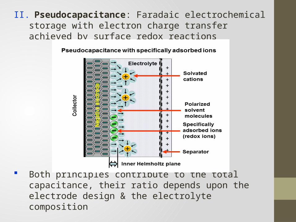
II. Pseudocapacitance: Faradaic electrochemical storage with electron charge transfer achieved by surface redox reactions
Both principles contribute to the total capacitance, their ratio depends upon the electrode design & the electrolyte composition
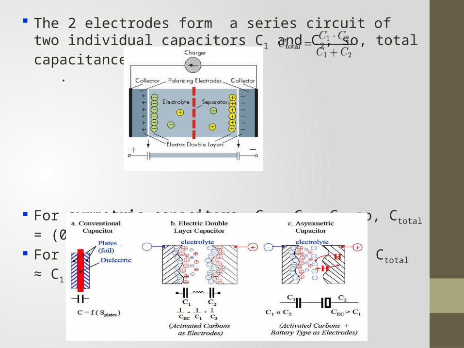
The 2 electrodes form a series circuit of two individual capacitors C1 and C2, so, total capacitance is given by .
For symmetric capacitors, C1 = C2 = C, so, Ctotal = (0.5) C For asymmetric capacitors, C1 << C2, so, Ctotal ≈ C1

TYPES Different types of supercapacitors, based on the type of
electrode are as follows.I. Electrochemical double-layer capacitors (EDLCs): Have activated carbon electrodes or derivatives No charge-transfer, non Faradaic Advantages: Higher energy density than conventional capacitors,
comparable power densities, greater cyclability Disadvantage: Cannot match energy density of mid-level batteriesII. Pseudocapacitors: Have metal oxide or conducting polymer electrodes Ions diffuse into pores, undergo fast, reversible surface
reactions

Advantage:Higher energy density & capacitance than EDLCs Disadvantages:Lower power density than EDLCs, limited life cycle,
expensive electrode materialIII. Hybrid Capacitors: combine the advantages & mitigate the disadvantages of
the first 2 types 3 types of electrodes: composite, asymmetric, battery-
type Advantages:Most flexible performance, high energy and power
density without sacrifices in cycling stability Disadvantages:Relatively new and unproven, more research required

CONSTRUCTION
• A supercapacitor cell consists of 2 electrodes, a separator, and an electrolyte
I. Electrodes: Made of metallic collector and, of an active material Applied as a paste or powder on metal foils Smaller pore size increases capacitance and energy density
but also increases ESR and decreases power densityII. Electrolytes: Provide electrical connection between electrodes Should be chemically inert, non-corrosive, less viscous Determine operating temperature range, voltage, ESR, capacitance Organic electrolytes give higher energy density, but lower
power density

Aqueous electrolytes have higher power density, conductivity III. Separators: Ion-permeable membrane, allowing charge transfer but
forbidding electronic contact between the electrodes Should be porous to ions, chemically inert Examples: PAN films, woven glass fibres• The construction is rolled/folded to cylindrical/rectangular
shape, stacked in Al can, impregnated with electrolyte that enters electrode pores
• The housing is hermetically sealed to ensure stable bahaviour
C1
C2
C3
C4
C5
+--
Ultracapacitor stack:

MODELLING
• A first order approximation of EDLC behaviour is a circuit consisting of ESR and EPR or Rleakage
• A more accurate model presents a circuit with cascaded RC elements, containing immediate, delayed and long-term branches, and Rlea

• A treatment of the capacitance in porous electrodes results in each pore being modelled as a transmission line.
• The transmission line models a distributed double-layer capacitance and a distributed electrolyte resistance that extends into the depth of the pore.
ELECTRICAL PARAMETERS
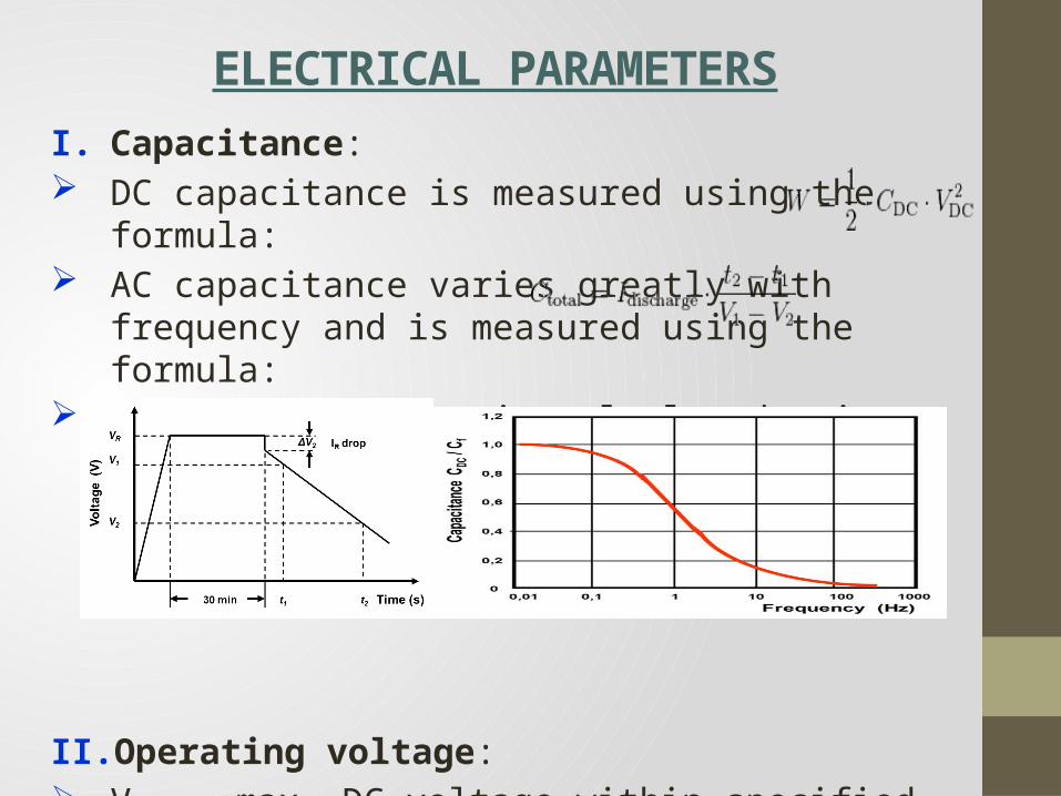
I. Capacitance: DC capacitance is measured using the formula: AC capacitance varies greatly with frequency and is
measured using the formula: Discharge current is calculated using the standards given
for different application conditions.
II. Operating voltage: Vrated- max. DC voltage within specified temp. range,
includes safety margin for electrolyte breakdown voltage

Applications require values more than Vrated, so, series connection is required, for which balancing is also needed
III. Internal resistance: DC resistance is calculated using the formula:
This is not same as ESR(rated value). It is time-dependent & affects charge/discharge currents
and times.IV. Current load and cycle stability: Much higher than for rechargeable batteries Internal heat generated: Lower current load increases life, number of cycles For “peak-power current”, robust design is required
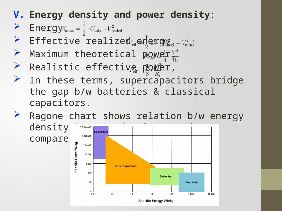
V. Energy density and power density: Energy, Effective realized energy, Maximum theoretical power, Realistic effective power, In these terms, supercapacitors bridge the gap b/w
batteries & classical capacitors. Ragone chart shows relation b/w energy density & power
density, used to compare performance

VI. Lifetime: Depends on capacitor temperature & voltage applied Higher temp. causes faster evaporation of electrolyte Acc. to standards, capacitance reduction of 30% &
resistance increase of 4 times is a “wear-out failure” Manufacturers specify it as “tested time(hrs)/max. temp.”,
using endurance test For every 10 C rise in temp., estimated life doubles. ̊�
Development of gas depends on the voltage. No general formula relates voltage to lifetime.

VII. Self-discharge: Caused because of surface irregularities in electrodes Known as leakage current Depends on capacitance, voltage, temperature &
chemical stability of electrode/electrolyte combination It is low at room temp.,specified in hours, days or weeksVIII.Polarity: In theory, supercapacitors have no polarity, but
recommended practice is to maintain the prod. polarity Polarities differ for capacitors and batteries. A –ve bar in the insulating sleeve identifies the cathode.

STANDARDS
IEC/EN 62391-1, for use in electronic equipment (further has 4 application classes) IEC 62391-2, for power application IEC 62576, for use in hybrid vehicles BS/EN 61881-3, railway applications, rolling stock
equipment

APPLICATIONS
• Time t a supercapacitor can deliver constant current is given as
• For constant power P, this time is given by
• Potential applications: pulse power systems (defibrillators, detonators, lasers), load levelling, UPS, quick charge applications (wireless power tools), high cycle and long life systems (sensors, metro buses), all-weather applications
• In general, there are 2 domains of application.I. High power applications, where short time power peaks
are required. Examples: HEVs, startersII. Low power applications, where batteries have insufficient
lifetime performance. Examples: UPS, security systems

• Typical applications:Consumer electronics Tools Buffer powerVoltage stabiliser Energy harvestingMedical TransportEnergy recuperation
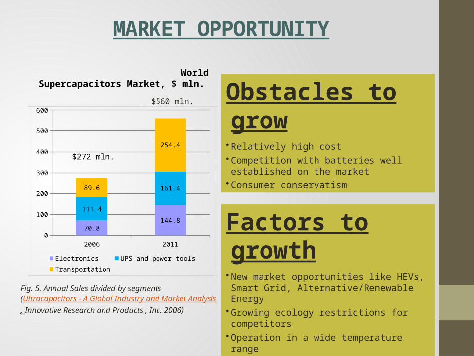
MARKET OPPORTUNITY
Obstacles to grow
• Relatively high cost• Competition with batteries well established on the market
• Consumer conservatism
Factors to growth• New market opportunities like HEVs, Smart Grid, Alternative/Renewable Energy
• Growing ecology restrictions for competitors• Operation in a wide temperature range• Good prospects or a combined power supply
$560 mln.
Fig. 5. Annual Sales divided by segments(Ultracapacitors - A Global Industry and Market Analysis, Innovative Research and Products , Inc. 2006)
2006 20110
100
200
300
400
500
600
70.8144.8
111.4
161.489.6
254.4
Electronics UPS and power tools
Transportation
$272 mln.
World Supercapacitors Market, $ mln.

CONCLUSION• Supercapacitors may be used wherever high power delivery
or electrical energy storage is required. Hence, numerous applications are possible.
• Their use allows a complementation of normal batteries. In combination with batteries, they can improve maximum instantaneous output power and battery lifetime.
• Major areas of R&D in supercapacitors (future of supercaps):
Reduction of material impurities (that cause self-discharge)Improvement in fabrication & packaging methods Reduction in the ESR to increase powerOptimization of electrolytes & electrodesFurther exploration of hybrid capacitors- the most
promising, but least developed supercap technology

THANK YOU