superfrac brochure
DESCRIPTION
KG-Tower SuperFrac BrochureTRANSCRIPT

The patented technologies used in SUPERFRAC® Trays (Figure 1)are the culmination of over twenty years of comprehensive traydevelopment work. The unique combination of SUPERFRACpatented technologies and design strategies produces the highcapacity and the maximum vapor/liquid contact efficiency achievable on a cross-flow distillation tray as shown in Figure 2. As a result, the SUPERFRAC tray gives the highest economic benefit to operators of distillation columns seeking solutions forboth new construction and revamp projects.
A well-designed conventional tray generally provides the mosteconomically attractive solution for grass-roots column construction projects. However, as the operator’s throughputand product requirements increase, the original trays becomethe primary constraint. Conventional tray design limitationsinclude:
• Liquid and/or vapor maldistribution that can reduce tray efficiency and lead to premature flooding because of entrainment.
• Less-than-optimal downcomer design that can ultimately resultin premature downcomer flooding.
Such performance issues of conventional trays have been recognized for many years. Koch-Glitsch has invested significantresearch and development resources to understand these issuesand to strategically address each one of them. SUPERFRAC traysand the know-how to design and apply them are the products ofthat investment.
Koch-Glitsch has targeted three major areas for enhancing theperformance of conventional trays:
• Advanced downcomer technology
• Active area enhancements
• Inlet area enhancements
1
SUPERFRAC® High Performance Trays
Figure 1. Two-Pass SUPERFRAC ® tray
Figure 2. Tray Operating Regimes
The SUPERFRAC® tray is a high-performance cross-flow tray that has the highest combined capacity and efficiency of all cross-flow trays tested at FRI.

2
Advanced Downcomer TechnologyA thorough understanding of downcomer flooding mechanisms in a wide variety of services is critical to successful application of high performance tray technology. Advanced downcomer technology developed by Koch-Glitsch provides the capability to accurately size and shape the downcomer, which provides the following benefits:
• Conventional downcomers for standard tray construction and simple installation
• Truncated downcomers to maximize active area for vapor-liquid contact
• Multi-chordal side downcomer skirts for longer flowpath length and greater efficiency
• Multi-stage downcomers for additional liquid-handling capacity
• Multi-pass downcomers for reduced weir loading and improved column capacity
• PURGETM downcomers as the ultimate solution for sediments in severe fouling services
Active Area Enhancements
Koch-Glitsch has developed a variety of valve styles and technologiesto enhance the vapor-liquid contacting that takes place on a tray deck,including:
• MINIVALVE® Decks
- Fixed valves, see Figure 3
- Floating valves, see Figure 4
• Large diameter fixed valves
• Bubble promoters
• Proprietary design techniques
The variety of valve styles and technologies are used to enhance the effective bubbling activity on the tray and improve the flow of fluid across the tray. This results in improvement to both hydraulic performance and mass transfer efficiency on the deck.
Inlet Area Enhancements
Inlet area enhancements, such as bubble promoters, can provide improved capacity, better froth initiation, and improvedbubbling activity on the tray, thus also increasing vapor-liquid contact efficiency.
SUPERFRAC trays use inlet area enhancements to eliminate the vapor and liquid maldistribution and stagnant zones thatcan occur on conventional trays. These enhancements promote uniform flow distribution, which improves the hydraulicperformance and contact efficiency of the tray.
Enhancements
Figure 3. MINIVALVE Deck - Fixed Valves
Figure 4. MINIVALVE Deck - Floating Valves

Fouling Services
Emergency Delivery
3
Moderate Fouling Systems
For moderate fouling systems, large diameter fixed valves, such asthe VG-10 (Figure 5), or the patented PROVALVE® unit (Figure 6) can be used on several SUPERFRAC configurations toreduce the tendency to foul.
Extreme Fouling Systems
For extreme fouling services, Koch-Glitsch offers SUPERFLUX®
Trays, which can employ many of the capacity and efficiency features of SUPERFRAC trays. SUPERFLUX trays are designed toincrease run time in fouling applications. Koch-Glitsch can addressthe specific fouling characteristics present in your operation withour proprietary technology offered on SUPERFLUX trays.
The PURGE™ Downcomer (Figure 7) is available for severefouling applications, such as polymer slurry, acrylonitrile, and butadiene services.
Emergency Delivery
Koch-Glitsch has a wide variety of tray products to provide optimum performance whatever your application. Many commonmaterials are in stock and trays can be quickly manufactured to get you back on line.
For emergencies, call the Hotline of your nearest Koch-Glitsch office.
• In the US, call the Hotline at 1-888-KOCH-911.
• In Europe, call 0044 1782 744 561, +39-06-928-911 or your local Koch-Glitsch office.
Figure 5. VG-10 Valves
Figure 6. PROVALVE Tray
Figure 7. PURGE Downcomer

• Conventional-style downcomers that are either straight or sloped
• Custom designs for specific application requirements
• Bolted design
• Valve options: VG-0, VG-10, PROVALVE, MV-1 and CRV valves
• Optimized liquid push• Bubble promoters• FLEXILOCK® Construction
Conventional Downcomer SUPERFRAC® Trays
PLUSTM Technology for SUPERFRAC® Trays
4
Construction Details Design Options
• Fits most SUPERFRAC tray configurations
• Custom designs for specific application requirements
• Installed below tray deck • Bolted design
• Valve options: VG-0, VG-10, PROVALVE, MV-1 and CRV valves
• Optimized liquid push• Bubble promoters for applicable
liquid rates• Proprietary design techniques• FLEXILOCK construction
Construction Details Design Options
4 Diameters from 3 ft [900 mm]4 Fouling resistant with large diameter
fixed valves4 Downcomer design provides simple
revamps 4 No extra active area over conventional
designs
Conventional downcomer SUPERFRAC trays useactive area enhancements and may include inlet area enhancements. Refer to page 2 for additionaldescriptions of enhancements.
The straightforward design of the downcomersallows use of standard tray construction and simplifies installation, which may provide a lowercost solution.
Some improvements in capacity and efficiency arepossible over conventional trays by changing theactive areas. In some cases, the higher capacityvalves and optimized liquid push can achieve revamp goals without downcomer modifications.
4 Diameters from 3 ft [900 mm]4 Applications with low liquid rates4 Available with most downcomer designs
The patented PLUS Technology acts as a deentrainmentdevice and can decrease the efficiency loss that oftenoccurs in low liquid and high vapor rate applications.In these types of conditions, it is common for highvapor rates to blow the liquid off the trays.
While the PLUS Technology will not prevent a trayfrom blowing dry, it does help offset the efficiencylosses that occur because of high entrainment in low liquid rate services. Gains of 5% in useable (efficient) capacity are typical.
The PLUS Technology is installed below each tray andhelps reduce the entrainment of liquid droplets fromone tray to the next.
The deentrainment device is a customized design thattypically uses a specifically designed FLEXIPAC®
Structured Packing. Because structured packing isused, this technology typically is not applied in foulingservices.
Figure 8. Conventional Downcomer SUPERFRAC Trays
Figure 9. PLUS Technology for SUPERFRAC Trays
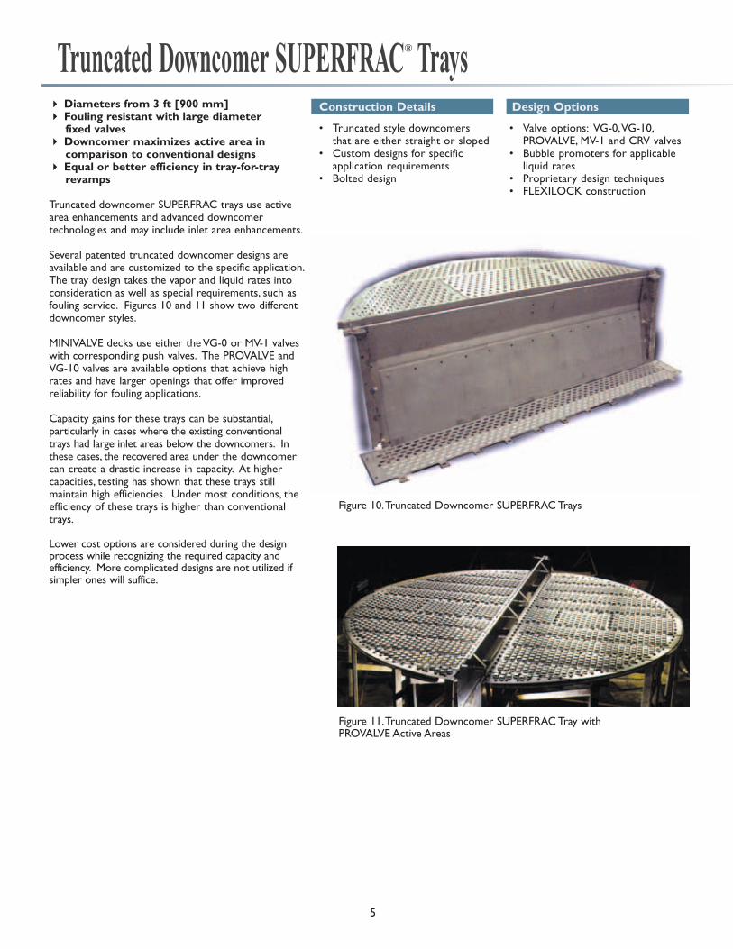
Truncated Downcomer SUPERFRAC® Trays• Truncated style downcomers
that are either straight or sloped• Custom designs for specific
application requirements• Bolted design
• Valve options: VG-0, VG-10, PROVALVE, MV-1 and CRV valves
• Bubble promoters for applicable liquid rates
• Proprietary design techniques• FLEXILOCK construction
4 Diameters from 3 ft [900 mm]4 Fouling resistant with large diameter
fixed valves4 Downcomer maximizes active area in
comparison to conventional designs4 Equal or better efficiency in tray-for-tray
revamps
Truncated downcomer SUPERFRAC trays use activearea enhancements and advanced downcomer technologies and may include inlet area enhancements.
Several patented truncated downcomer designs areavailable and are customized to the specific application.The tray design takes the vapor and liquid rates intoconsideration as well as special requirements, such asfouling service. Figures 10 and 11 show two differentdowncomer styles.
MINIVALVE decks use either the VG-0 or MV-1 valveswith corresponding push valves. The PROVALVE andVG-10 valves are available options that achieve highrates and have larger openings that offer improvedreliability for fouling applications.
Capacity gains for these trays can be substantial, particularly in cases where the existing conventionaltrays had large inlet areas below the downcomers. Inthese cases, the recovered area under the downcomercan create a drastic increase in capacity. At highercapacities, testing has shown that these trays still maintain high efficiencies. Under most conditions, theefficiency of these trays is higher than conventionaltrays.
Lower cost options are considered during the designprocess while recognizing the required capacity and efficiency. More complicated designs are not utilized ifsimpler ones will suffice.
Construction Details Design Options
5
Figure 10. Truncated Downcomer SUPERFRAC Trays
Figure 11. Truncated Downcomer SUPERFRAC Tray with PROVALVE Active Areas

4 Diameters from 3 ft [900 mm]4 Design maximizes active area over
conventional designs4 Downcomer design utilizes entire tray space4 Equal or better efficiency in tray-for-tray
revamps
The patented multi-chordal downcomer SUPERFRACtray (Figure 12) uses active area enhancements andadvanced downcomer technologies and may includeinlet area enhancements.
One advantage of the multi-chordal downcomer designis that the downcomer uses the full vertical tray space,which minimizes downcomer limitations.
MINIVALVE decks use either the VG-0 or MV-1 valveswith corresponding push valves.
Capacity gains for these trays can be substantial particularly in cases where the existing conventionaltrays had large inlet areas below the downcomers(Figure 13). In these cases, the recovered area underthe downcomer can create a drastic increase in capacity. At higher capacities, testing has shown thatthese trays still maintain high efficiencies. Under mostconditions, the efficiency of these trays is higher thanconventional trays.
The forward-lateral push provided by the optimizedliquid push design promotes uniform liquid and vapordistribution across the entire tray deck. This suppressesjet flooding and permits operation at higher flow rates.The typical liquid recirculation found on most traysresults in lower efficiency and capacity. This liquid recirculation is eliminated with the appropriate liquid push design (Figure 14).
The multi-chordal shape of the side downcomer at thebottom provides additional benefits.
• Equalized liquid flow patterns across the tray
• Increased flow path length
• Increased vapor-liquid contact time
• Improved efficiency
• Increased bubbling area and tray capacity
In this design, the bottom downcomer area is locatedover the tray support ring, thereby utilizing an areathat cannot be used as an active area.
The shape of the multi-chordal downcomer allows a conversion from straight to sloped downcomerswithout the use of downcomer adapter bars. Thissaves the extra cost of the adapters and the field timeneeded to install them. It also eliminates the need toweld to the vessel shell.
Multi-Chordal Downcomer SUPERFRAC® Trays
6
• Multi-chordal style side downcomers
• Custom designs for specific application requirements
• Bolted design
• Valve options: VG-0, VG-10, PROVALVE, MV-1 and CRV valves
• Optimized liquid push• Bubble promoters for applicable
liquid rates• Proprietary design techniques• FLEXILOCK construction
Construction Details Design Options
Figure 12. Typical Multi-Chordal Downcomer
Conventional Tray SUPERFRAC® Tray
Figure 14 Liquid Flow Distribution Comparison
Figure 13. SUPERFRAC and Conventional Tray Capacity Curves
Liquid Flux
CS
Conventional Valve Tray
SUPERFRAC - MCD

Multi-Stage Downcomer SUPERFRAC® Trays4 Diameters from 3 ft [900 mm]4 Specifically designed for high liquid rates 4 Downcomer design maximizes active area
and utilizes entire tray space
The patented multi-stage downcomer SUPERFRACtray (Figure 15) uses active and inlet areaenhancements and the most advanced downcomertechnologies.
The multi-stage downcomer is used only for highliquid loads with weir loadings in excess of 120gpm/ft (90m3/hr/m) and is custom designed for each application’s requirements. One advantage ofthe multi-stage downcomer design is that the downcomer uses the full vertical tray space, whichminimizes downcomer limitations.
The additional liquid-handling capacity of the multi-stage downcomer can often eliminate theneed for downcomer adapters. This reduces installation time and lowers equipment and fieldlabor costs. It can also reduce downcomer backupby lowering the amount of liquid that must passunder the downcomer edge.
Capacity gains for these trays are substantial. At high capacities, testing has shown that these trays still maintain high efficiencies. Under mostconditions, the efficiency of these trays is higherthan conventional trays.
• Multi-chordal style side downcomer
• Custom designs for specific application requirements
• Bolted design • Bubble promoters
• Valve options: VG-0, VG-10, PROVALVE, MV-1 and CRV valves
• Optimized liquid push• Proprietary design techniques• FLEXILOCK construction
Construction Details Design Options
Multi-Pass Downcomer SUPERFRAC® Trays4 Diameters from 13 ft [3962 mm]4 High liquid rates4 Multiple downcomer designs
In larger diameter columns, typical multi-passdesigns are limited to four passes. However, forapplications that require more than four passes, the proprietary multi-pass downcomer design canbe used to reduce weir loading and improve thecapacity of the column.
Koch-Glitsch has successfully designed large diameter columns that use these multi-pass designtechniques in 6-pass or 8-pass configurations.Modest capacity increases with these trays are possible in comparison to the best designed 4-pass SUPERFRAC trays.
The downcomer configuration for a multi-passdesign typically is the multi-chordal design; however,virtually any other configuration can be used.
• Truncated, multi-chordal or multi-stage downcomer design
• Custom designs for specific application requirements
• Bolted design• Bubble promoters
• Valve options: VG-0, VG-10, PROVALVE, MV-1 and CRV valves
• Optimized liquid push• Customized downcomer design• Proprietary design techniques• FLEXILOCK construction
Construction Details Design Options
7
Figure 15. Multi-Stage Downcomer SUPERFRAC Trays
Figure 16. Multi-Pass Downcomer SUPERFRAC Trays

4 Diameters from 3 ft [900 mm]4 Fouling resistant with large fixed valves4 Conventional downcomer design allows
simple revamps 4 PURGETM Downcomer design is the ultimate
solution for sediments4 Directional valves promote self-cleaning of
active area
To ensure the appropriate technologies are applied for each SUPERFLUX® Tray design, the client is contacted for specific characteristics of fouling thatmust be addressed. Features suitable for the specificapplication are then combined into a final design to produce a tray capable of longer run times betweencleaning shutdowns.
Conventional DowncomersSUPERFLUX trays with conventional downcomers useactive area enhancements and may have inlet areaenhancements. Large diameter fixed valves that arefouling resistant are a standard feature (Figure 17).
The straightforward design of the downcomers allows the use of standard tray construction and simplifies installation.
SUPERFLUX trays provide increased fouling resistance,which can lead to increased run times. Several valveoptions are available that promote self-cleaning of theactive areas. These valves have directional componentsthat utilize vapor energy to provide forward-lateral push on the froth. This action is critically important tomaintain proper tray activity and reduce residence timeof solids on the tray deck.
Particular attention is paid to the peripheral areas of the deck where stagnation may lead to solids deposition. Directional valves are placed in this area to both increase activity as well as promote a uniform flow profile. These components combine toreduce the residence time distribution and enhance the fouling resistance of the trays.
Such a tray design is suitable for processes which are particularly prone to active area fouling, such assour water strippers and beer strippers. In processes where downcomer fouling is known to cause frequent shutdowns, we recommend the PURGETM Downcomerconfiguration.
PURGETM DowncomersIf conventional downcomers do not provide the optimum design for resisting fouling in your application,Koch-Glitsch offers the PURGE downcomer (Figure 18).For very severe applications, the PURGE downcomerhas proven suitable to resist fouling for such services aspolymer slurry, acrylonitrile, and butadiene services.
The PURGE downcomer SUPERFLUX trays use active area enhancements and may have inlet areaenhancements. Very specific advanced downcomertechnologies have been applied to the PURGE downcomer trays.
SUPERFLUX® Trays
8
• Conventional style downcomers that are either straight or sloped.
• PURGE downcomers for very severe services
• Custom-engineered design for specific application
• FLEXILOCK construction
• Valve options: VG-0, VG-10, PROVALVE valves
• Proprietary design techniques• Bolted design• Electropolishing
Construction Details Design Options
Figure 17. SUPERFLUX Tray for Bioethanol Beer Stripper
Figure 18. SUPERFLUX Tray with PURGE Downcomer Option

Mechanical FeaturesOMNI-FIT® Technology
FLEXILOCK® Tray Construction
9
OMNI-FIT technology is a set of mechanical engineeringdesigns used to reduce the cost and downtime ofrevamps. These technologies include expansion rings,pedestal supports, downcomer adapters, and innovativetray designs that can minimize or eliminate welding onan existing tower. Efficiency and capacity enhancementscan be achieved by using OMNI-FIT technology for yournext turnaround project.
OMNI-FIT technology can be used to:
4 Increase theoretical stages
4 Change tray spacings
4 Change the number of passes
4 Modify downcomer sizes or configurations
4 Install multi-pass SUPERFRAC trays
4 Change tray orientation
4 Eliminate welding
4 Shorten turnarounds
4 Replace packing
4 And more…
®
Before After
Figure 19. Revamp using OMNI-FIT Technology
The patented FLEXILOCK tray joint allows rapid installationof tray panels in vessel shops or in the field. FLEXILOCKtray construction eliminates the requirement for hardwarebetween adjacent tray panels and provides for error-freedeck installations.
FLEXILOCK tray construction can be used to:
4 Reduce hardware requirements
4 Improve valve coverage
4 Provide error-free deck installation
4 Dramatically reduce installation time
4 Strengthen joint and uplift tolerance
4 Promote in-shop installations
4 Cancel vibration-induced panel shifting
Figure 20. FLEXILOCK Tray Construction

10
HORIZON® Technology
HORIZON technology is a set of mechanical construction techniques developed specifically for in-shop installation of trays with the vessel in the horizontal position. Using the patented FLEXILOCK tray construction as its primary building block, this special mechanical design prevents the problems that can occur when conventionally designed trays are installed with the vesselin the horizontal position. These problems include inefficient installationsequencing, part deforming/breaking, panel shifting, joint dislodging, extra fieldinspecting and field readjusting of tray parts.
If you plan to shop-install trays, then you need the assurance provided byHORIZON technology.
The patented SATURN technology can reduce the total installed cost of newdistillation columns with its combination of innovative tray designs and simpletower attachments.
When crossflow trays are used, conventional designs use horizontal ring segments to support trays decks and vertical bolting bars to support traydowncomers. With the SATURN technology, all of the cross flow tray parts aresupported from the horizontal ring.
SATURN technology brings together:
4 The high efficiency, high capacity, low cost, and reliability of crossflow trays
4 The simple rings of dualflow trays
SATURN® Technology
SPEED-WAY® Manways
Why do this?When you can
do THIS!
Figure 23. SPEED-WAY Manways
At last, a design that allows you to easily add quick-opening manways to your existing trays. Just remove the existing manway or active panels and replace them with SPEED-WAY panels (Figure 23).
These quick-opening manways are especially beneficial when:
4 Turnaround manpower is limited
4 Short downtime is critical
4 Routine inspections are required
If you have a need to tunnel through your column on a routinebasis, SPEED-WAY manways are a must.
Figure 21. HORIZON Construction Enhancements
Figure 22. Application of SATURN Technology

MetalTrays are available in any formable, weldable sheetmetal material. The most common materials for traysare: • Carbon steel• Stainless steel, Ferritic, Austenitic, Duplex, Martensitic• Nickel alloys• Copper alloys• Titanium, Zirconium
Trays are not normally stress relieved or annealed andtypically do not conform to pressure vessel standards.
Trays fabricated from sheet metal materials are typicallysupplied in "as-sheared" condition.
BoltingStandard bolting conforms to AISI specifications. Boltingconforming to ASME specifications is available by specialrequest.
CertificationMaterial certification is available for all fabricated internals.Positive Material Identification (PMI) testing is available byspecial request.
Gasketing
For multi-piece trays requiring gasketed joints, manychoices of gasket material are available. Where gasketingis required, braided fiberglass tape is supplied as thestandard for linear joints. Depending on the service,FLEXITALLIC® SF2400, expanded PTFE or spiral woundstainless steel with flexible graphite filler gaskets are supplied as the standard for flanged connections. Other gasket materials are available by special request.
Manway Access
All trays are designed in sections to pass through vesselmanways. Tower internals are designed to pass through a vessel manway of 18 in [450 mm] minimum insidediameter, unless otherwise specified. Larger manwaysoften provide the ability to optimize the design of components for faster, easier installation. Please providemanway locations and inside diameters at the time ofinquiry.
Construction Details
11
Up to 18[Up to 457]
18.1 – 24.24[458 – 615]
24.25 – 48.24[616 – 1225]
48.25 – 72.24[1226 – 1835]
72.25 – 96.5[1836 – 2450]
96.6 – 144.5[2451 – 3670]
144.6 – 168.7[3671 – 4285]
168.8 – 216.3[4286 – 5495]
216.4 – 240.5[5496 – 6110]
Trays Resting on orClamped to Support
Ring
0.75[20]
1.0[25]
1.5[40]
2.0[50]
2.5[65]
3.0[75]
3.5[90]
4.0[100]
4.5[115]
Trays Through-Bolted or
Using LevelingScrews
1.5[40]
1.5[40]
2.0[50]
2.0[50]
2.5[65]
3.0[75]
3.5[90]
4.0[100]
4.5[115]
All dimensions are expressed as inches [millimeters]
Tower ID
Minimum Support Ring Widths
Scope of SupplyFor the trays in this brochure, Koch-Glitsch supplies allremovable parts.
The trays do not include vessel attachments for connectionor support, unless specifically stated in the item description.Vessel attachments may be quoted/supplied separately.Examples of attachments that may be required are:• Support rings• Sump frames• Internal flanges at feed inlet nozzles• Wall clips for support• Downcomer clamping bars• Beam seats
If the support ring size is other than these listed above, special consideration must begiven to the plate diameter and vessel tolerances.
Figure 24. Minimum Support Ring Widths

Obtaining desired tower performancerequires the proper handling of liquid andvapor entering the column. The types offeeds or inlets into a column can generallybe classified into three major categories:
• Liquid only (contains less than 1% of vapor by volume)
• Mixed liquid and vapor, flashing orsuppressed flash
• Vapor
The selection criteria for each category offeed device is unique
Liquid-Only Feeds
Among the factors Koch-Glitsch considersin designing a liquid feed device are:
• Type of tray
• Expected tray performance
• Flow rate
• Operating range
• Degree of sub-cooled liquid
• Requirements for mixing
The feed arrangement for these conditionsdepends on the tray type. Please consultwith a Koch-Glitsch technical representativefor recommendations.
Liquid-Vapor and FlashingFeeds
For mixed liquid-vapor or flashing feeddevices above a tray, the selection depends on:
• Tray type
• Liquid and vapor flow rates
• Turndown
• Column height needed for disengagement and vapor distribution
• Requirements for mixing
In all cases, separating the vapor and the liquid phases is a primary concern. In some cases, the requirements for additional pre-distribution may altercertain tray designs.
Vapor-Only Feeds
Two factors must be considered whenchoosing the proper device for a vapor-only feed.
• The kinetic energy of the inlet vaporin relation to the pressure drop across the trays, the feed nozzlearrangement and the tower separationrequirements.
• If there is a large difference in the composition and/or temperature between the inlet vapor stream and bulk vapor flow, mixing the two vaporsoptimizes the performance of the trays.
Specific equipment for vapor distribution may not be required if sufficient column height is available forequalization or if the pressure dropacross the trays is sufficient to provideproper vapor distribution.
CFD Modeling
Good vapor distribution is essential toachieve superior separation efficiency.Poor vapor distribution is often a majorsource of problems.
Koch-Glitsch combines modernComputational Fluid Dynamics (CFD)modeling technology with its engineeringexpertise to analyze vapor and liquid distribution when evaluating the performance of existing equipment anddeveloping new, improved designs. Thisinvolves computer modeling of the 3- dimensional configuration of the column internals to provide detailed predictions of fluid flow (velocity profiles,and so forth). See Figure 25.
Koch-Glitsch offers CFD services for thefollowing tasks:• Development and optimization of new
mass transfer equipment
• Troubleshooting or analysis of existing equipment
• Confirmation of equipment designs prior to fabrication and installation
Feed Devices
12
X-Velocity: Unequal Legs(Perspective View)
Figure 25. CFD Study for Single VG-0 Valve

Applications
13
C3 Splitter Revamp with Multi-Chordal, Multi-Pass SUPERFRAC® Trays
SUPERFRAC trays can be used in new construction and revamp opportunities for virtually any service in which conventional sieveand valve trays are used. They are especially beneficial in applications requiring a large number of mass transfer stages, or wheremass transfer efficiency is critical to the economics of the operation. Examples include superfractionators (ethylene, propylene),light hydrocarbon fractionators, splitters in chemical and petrochemical applications and aromatic services.
A significant revamp of a C3 splitter unit was completed in 2000 to obtain additional capacity over first generation high capacity trays. Because of the number of stages involved in this propylene /propane separation, the splitter is actually twocolumns. The feed is to the middle of the lower column, which has both a stripping and a rectifying section. The upper column contains additionalrectifying trays. Figure 26 is a simplified process flow diagram of the unit.
The tray design changes included SUPERFRAC styledowncomers to maximize active area, push valves,fixed MINIVALVE units, higher open area, reduced weirheight, number of passes increased to six, and trayspace increased below the feed.
OMNI-FIT revamp techniques were used to changethe number of passes and tray spacing without weldingto the column shells. In addition, the feed inlet nozzlewas relocated to a higher position on the column.
Even with the 6-pass design and reduced flow pathlength, the overall tray efficiency was still measured in the 90% to 95% range. The end result was goodefficiency and at least a 15% capacity improvementover the previous high capacity trays.
Before After
Diameter, ft 16 16Tray Configuration 4-Pass 6-PassTray Type 1st Generation Multi-Chordal
High Capacity SUPERFRAC Trays Trays
Deck Type Movable Valves VG-0Above Feed
Number of Trays 196 178Tray Spacing, inches 22 22
Below FeedNumber of Trays 44 49Tray Spacing, inches 22 27.5
Propylene Rate, MM lb/yr 820 958Max wt% Propane Overhead 0.4% 0.4%Max lv% Propylene Bottoms 5.0% 5.0%
The table below summarizes some of the results.
OVERHEADACCUMULATOR
TRIM CONDENSER
CONDENSER-REBOILER
COMPRESSOR
PROPYLENEDE-ETHANIZER
BOTTOMS
C3
SPLI
TTER
C3
SPLI
TTER
Figure 26. C3 Splitter Simplified Process Flow Diagram

During the test run, the target design rate of 110% was met atthe midpoint of the first day with a target purity of 99.6% EDCin the overhead product stream. The product specification forthe 1,1,2 Trichloroethane impurity in the overhead was alsomet. Even though three trays were eliminated in the columnbecause of increased tray space, the required product puritieswere achieved at the same reflux rate.
The column has operated at 124% of original capacity over atwo-year period and has not lost operation time because oftray fouling. A comparison of the column’s performance beforeand after the revamp is shown in the table below.
A Vinyl Chloride Monomer producer wanted to revampits EDC Heavy Ends column to achieve a significantcapacity increase and eliminate frequent shutdownsbecause of tray fouling. Simulations of the operatingdata, evaluation of the tray hydraulics, and a gamma scanof the column revealed that the existing sieve trays wereat their operating limit.
The column upgrade included:
• Replacing all one-pass sieve trays above the feed with one-pass SUPERFLUX® Trays on the same 15 in. trayspace.
• Increasing tray spacing below the feed from 15 in. to 18 in. without welding in new tower attachments.
• Replacing the tray immediately below the feed with a transition tray, which was used to mix the liquid from thetray above with the liquid from the feed and to distributethe mixed liquid to the two-pass trays below.
• Using expansion tray rings and special downcomer adapters to support the new SUPERFLUX trays andeliminate field welding to the vessel wall.
14
EDC Heavy Ends Column Revamp
Before Revamp After Revamp
Feed Rate, gpm 327 406OVHD Product Rate, gpm 310 385OVHD EDC Purity, wt% 99.60 99.61OVHD Temperature, °F 221 236Bottom Temperature, °F 250 252 – 257Column Pressure Drop, psi 9.0 8 – 9.5Capacity 100% 124%Reflux Ratio (L/D) 0.48% 0.45 – 0.52%
Depropanizer Revamp with Two Types of SUPERFRAC® Trays
23
30
29
28
27
26
25
24
22
21
7
20
19
18
17
16
15
14
13
12
11
10
9
8
6
5
4
3
2
1
23
24
22
21
7
20
19
18
17
16
15
14
13
12
11
10
9
8
6
5
4
3
2
1
40
39
38
37
36
35
34
33
32
31
REFLUX
COLD FEED
Before1990 Revamp
OVERHEADVAPOR
TRAYS 1-40
1-PASSSIEVE TRAYS
REBOILERVAPOR RETURN
DRAW TOREBOILER
REFLUX
After1990 Revamp
TRAYS 1-24
1-PASSNEW SIEVE DECKS
OVERHEADVAPOR
COLD FEED
REFLUX
After2000 Revamp
DRAW TOREBOILER
REBOILERVAPOR RETURN
HIGH PERFORMANCELIQUID DISTRIBUTOR
DRAW TOREBOILER
REBOILERVAPOR RETURN
HIGH PERFORMANCELIQUID DISTRIBUTOR
20.3 FT INTALOXSTRUCTUREDPACKING 2T
20.3 FT INTALOXSTRUCTUREDPACKING 2T
OVERHEADVAPOR
TRAYS 1-15
1-PASSSUPERFRACTRAYS
TRAYS 16-24
1-PASSSUPERFRACTRAYS
®
®
COLD FEED
23
24
22
21
7
20
19
18
17
16
15
14
13
12
11
10
9
8
6
5
4
3
2
1
In 1990, the sieve trays in the rectifying section were upgradedand the stripping section trayswere replaced with INTALOX®
Structured Packing to increasethe capacity from 4,000 barrelsper day to 6,000 barrels per day.In 2000, the operator wanted to increase the capacity again. At that point, the sieve trays inthe rectifying section were thelimitation. These trays werereplaced with conventional and truncated downcomerSUPERFRAC trays.
The column now handles a maximum feed rate of 7,100 barrels per day. Upstream equipment, and not the columninternals, now limits the capacityof the column. The next limitationin the column will most likely be the structured packing. A post-revamp performance testindicates that the SUPERFRACtrays in the rectifying section areoperating with tray efficiencies inexcess of 100%.
Figure 27. Column Layouts Before and After Revamps

Koch-Glitsch Corporate Offices
Worldwide Headquarters
Koch-Glitsch, LP
4111 East 37th Street North Wichita, KS 67220 – United States tel: (316) 828-5110 fax: (316) 828-7985
Europe
Koch-Glitsch Italia S.r.l.
Viale Giulio Cesare 29 24124 Bergamo – Italy tel: +39 035 2273.411 fax: +39 035 2273.400
Asia
Koch-Glitsch Korea, Ltd.
17-8, 8F, Dongsung Bldg. Yoido-dong, Youngdeungpo-ku
Seoul 150-874 – Korea tel: +82-2-3276-7500 fax: +82-2-3276-7590
Koch-Glitsch (A division of Koch Chemical Technology Group India Pvt. Ltd). Corporate Park II, 10th Floor Sion-Trombay Road Chembur, Mumbai 400 071 – India tel: +91 22 6771 7171 fax: +91 22 6771 7161
For a complete list of our offices and facilities, visit us on the Web at www.koch-glitsch.com.
Emergency Numbers US: 1-888-KOCH-911. Europe: +39-06-928-911, +44-1782-744561, or your local Koch-Glitsch office. Asia Pacific: Contact your local Koch-Glitsch office.
Trademarks FLEXIPAC, HORIZON, INTALOX, KITTEL, KOCH-GLITSCH, “K” KOCH-GLITSCH, MINIVALVE, OMNI-FIT, PROVALVE, SATURN, SPEED-WAY, SUPERFLUX, SUPERFRAC, and ULTRA-FRAC are registered trademarks of Koch-Glitsch, LP and are registered in the US and various countries worldwide. FLEXILOCK is a registered trademark of Koch-Glitsch, LP and is registered in the US. PLUS and PURGE are trademarks of Koch-Glitsch, LP. All other trademarks, service marks, or registered trademarks that appear in this document are the trademarks or service marks of their respective owners.
Patents Bubble promoter, FLEXILOCK®, INTALOX® structured packing, KITTEL®. OMNI-FIT®, multi-stage downcomer, multi-chordal downcomer, PLUS™, PROVALVE®, SATURN®, SPEED-WAY®, SUPERFLUE®, SUPERFRAC®, and truncated downcomer technologies are protected by various patents worldwide.
Legal Notice The information contained in this bulletin is believed to be accurate and reliable, but is not to be construed as implying any warranty or guarantee of performance.
Bulletin KGSF-1. Rev. 3-2010. Printed in U.S.A. © 2006-2010 Koch-Glitsch, LP. All rights reserved.