superlift 4†lift system for 1998 - 2009 ford ranger 4wd
TRANSCRIPT

FORM #9909.01-111708 PRINTED IN U.S.A. PAGE 1 OF 14
SUPERLIFT SUSPENSION SYSTEMS 300 Huey Lenard Loop Rd.
West Monroe, Louisiana 71292 Phone: (318) 397-3000
Sales / Tech: 1-800-551-4955 FAX: (318) 397-3040
Superlift 4” lift system for 1998 - 2009
FORD RANGER 4WD with torsion bar front suspension INSTALLATION INSTRUCTIONS
INTRODUCTION Installation requires a professional mechanic. Prior to beginning, inspect the vehicles steering, driveline, and brake systems, paying close attention to the track bar, suspension link arms and bushings, anti-sway bars and bushings, tie rod ends, pitman arm, ball joints and wheel bearings. Also check the steering sector-to-frame and all suspension-to-frame attaching points for stress cracks. The overall vehicle must be in excellent working condition; repair or replace all worn parts. Read instructions several times before starting. Be sure you have all needed parts and know where they install. Read each step completely as you go. NOTES: • A special puller tool is required to load / unload the torsion bars. The tool is available
separately from Superlift (#9635). A similar tool is available from Ford or the Kent Moore Tool Group in Roseville, MI (Phone: 800-576-7375, Fax: 800-345-2233). Both Ford and Kent Moore use part number T95T-5310-AR.
• If your vehicle is equipped with vacuum operated hubs: Ford states that several other special tools are needed; refer to Steps 4, 6, 16, 17, and 18. Most professional installers will have these tools or an equivalent. Ford suggests that these factory front axle components be replaced every time the front hub assembly is disassembled. Although we have found that if the parts are in good condition and carefully removed, they can be reused. There are two each of these Ford part numbers per vehicle:
#F87Z-1177-AA..... O-ring for wheel bearing hub-to-knuckle #F87Z-1177-BA.... O-ring for locking hub-to-wheel bearing hub #F87Z-1190-AA.... axle half shaft main seal
• The rear lift is sold separately and includes separate installation instructions. Options are blocks, a block / add-a-leaf combination, or replacement springs. FX4 requires part number 10914.
• A factory service manual must be on hand. The manual will contain fastener torque specifications, assembly techniques, and / or special tool requirements that are unique to this particular year and model vehicle.
• Do not add or fabricate any components to gain additional suspension height.
• Prior to attaching components, be sure all surfaces are free of grit, grease, undercoating, etc.
• Front end realignment is required.
• An arrow on diagrams indicates which direction is towards “front of vehicle”.

FORM #9909.01-111708 PRINTED IN U.S.A. PAGE 2 OF 14
• Use the check off box “ ” found at each step to help you keep your place. Two “ ” denotes that one box is for the driver side and one is for the passenger side.
PARTS LIST … The part number is stamped into each part or printed on an adhesive label. Identify each part and place the appropriate mounting hardware with it. PART NO DESCRIPTION NEW ATTACHING HARDWARE (Qty.- if more than one) (Qty.- if more than one)
01-9636 ....................... knuckle, driver side ...................... (2) 1/8” O.D. X 1-1/2” long cotter pin 02-9636 ....................... knuckle, passenger side ............. (2) 1/8” O.D. X 1-1/2” long cotter pin 55-21-9636 ................... differential torque bracket ............ (2) bushing half driver side \ rear (1) bushing sleeve , 2-3/8” long 55-04-9630 ................... (2) front differential drop bracket, (2) 7/16” X 3 -3/4”bolt passenger and driver side (2) 7/16” Nyloc nut (4) 7/16” USS washer 55-05-9630 ................... (4) crossmember drop bracket .... (4) 5/8” X 5” bolt (4) 5/8” Nyloc nut 55-06-9630 ................... crossmember tube, front .............. (8) 3/8” X 1-1/4” bolt (8) 3/8” Nyloc nut 55-07-9630 ................... crossmember tube, rear .............. (8) 3/8” X 1-1/4” bolt (8) 3/8” Nyloc nut 55-08-9630 ................... differential lateral support bracket 55-09-9630 ................... compression stop bracket, .......... (1) 8 mm X 1.25 mm X 120 mm bolt driver side 55-10-9630 ................... compression stop bracket, .......... (1) 8 mm X 1.25 mm X 120 mm bolt passenger side 55-25-9630 ................... torsion bar drop bracket, ............. (2) 7/16” X 1-1/4” bolt driver side (2) 7/16” Nyloc nut (2) 7/16” flat washer 55-24-9630 ................... torsion bar drop bracket, ............. (2) 7/16” X 1-1/4” bolt passenger side (2) 7/16” Nyloc nut (2) 7/16” flat washer 55-13-9630 ................... front skid plate ............................. (4) 7/16” X 4” bolt (optional) (4) 7/16” Nyloc nut (4) 7/16” flat washer (4) 3/4”O.D. X 1-1/4” long, tubing spacer (1) Superlift badge (attached) 55-26-9630 ................... (2) sway bar link, front ................. (4) 1/2” SAE flat washer (4) 7/16” SAE flat washer (2) 7/16” Stover nut (4) bushing half (2) spacer sleeve 55-16-9630 ................... (2) front brake hose ..................... (2) 5/16” X 1” bolt

FORM #9909.01-111708 PRINTED IN U.S.A. PAGE 3 OF 14
relocation bracket (2) 5/16” Nyloc nut 55-23-9630 .................. (4) cam washers 01-99195 ..................... (2) front limiting strap ................... (2) 7/16” x 1” bolt (2) 7/16” SAE washer (2) 7/16” nyloc nut 85330........................... (2) shock absorber, front .............. (2) shock boot, yellow (2) tie strap, black 85156........................... (2) shock absorber, rear ............... (2) shock boot, yellow (2) tie strap, black
FRONT DISASSEMBLY 1) PREPARE VEHICLE...
Place vehicle in neutral. Raise front of vehicle with a jack and secure a jack stand beneath each frame rail, behind the lower control arms. Ease the frame down onto the stands, place transmission in low gear or “park”, and chock rear tires. Remove front tires.
2) TORSION BAR REMOVAL...
On each side, scribe alignment marks to note the torsion bar’s indexing in relation to the adjuster arm. Also scribe marks to note the front end of the bar in relation to the lower control arm.
Label the bars (front / rear end, and driver / passenger side) because they must be reinstalled in the same position and orientation as they were removed.
[DIAGRAM 1] Remove the plate that covers the torsion bar adjuster arm assembly. The
plate and attaching hardware will be reused, but not in the same location. So go ahead and remove the nut clips from the crossmember lips [DIAGRAM 7].

FORM #9909.01-111708 PRINTED IN U.S.A. PAGE 4 OF 14
[DIAGRAM 2] Load the bars using a torsion bar puller tool (discussed in the NOTES section above) and remove the adjusting bolt and nut block. Unload the bar.
On each side, slide
the torsion bar forward into the Lower Control Arm (LCA) and the adjuster arm and insulator will fall free. The insulator is a rectangular shaped block located directly above the adjuster arm.
Steps 3 through 7 are performed one side at a time. Start at the driver’s side. 3) SWAY BAR LINK and OUTER TIE ROD END...
Disconnect the sway bar link from the sway bar body and the LCA.
Use a puller tool to separate the outer tie rod end from the knuckle. 4) BRAKE CALIPER and ROTOR...
WARNING: Asbestos fiber dust may be present on brake assemblies and is hazardous to health if inhaled. Brake assemblies should be cleaned using a vacuum recommended for use with asbestos fibers. The bag must be labeled per OSHA instructions, and the trash hauler notified of the bag’s contents. If an asbestos suitable vacuum is not available, cleaning should be done wet. If dust generation is still possible, technicians should wear government-approved toxic duct respirators.
Unbolt the brake caliper from the knuckle and tie it up and out of the way; the frame rail is a
good anchor point. Do not detach the brake hose from the caliper or let the caliper “hang” from the hose.
Remove the brake rotor and dust shield.
5) KNUCKLE...
For vehicles equipped with vacuum operated hubs: Use a hub puller tool to remove the locking hub assembly from the hub. If a puller is not available, carefully use a flat head screwdriver to pry the locking hub free. Remove the metal/plastic retainer ring on the CV axle stub shaft.

FORM #9909.01-111708 PRINTED IN U.S.A. PAGE 5 OF 14
For vehicles without vacuum operated hubs: Remove the CV axle nut. Retain. Disconnect the vacuum hose, and if equipped, the harness that captures the ABS wiring.
Both are located on the back side of the knuckle.
Using a plastic hammer, drive the axleshaft inward until it is loose inside the knuckle.
Remove the upper ball joint pinch bolt.
Remove the LCA ball joint cotter pin and castellated nut. The knuckle is now held only by the lower ball joint. Use a puller tool to free the joint then set the knuckle aside. Take care not to damage the seal which is press-fitted into the back side of the knuckle. If in good condition, the seal can be reused in the new Superlift knuckle (installed in a later step).
6) FACTORY SHOCK ABSORBER...
Place a jack under the LCA and raise it to a level position.
Remove and discard the factory shock absorber 7) LOWER CONTROL ARM...
Remove the two LCA-to-frame bolts and set the arm aside. Perform Steps 3 through 7 on passenger’s side. 8) DRIVESHAFT...
Scribe an alignment mark on the driveshaft and front axle pinion flange. Disconnect the axle end of the shaft and let it hang. Wrap the U-joint with tape to prevent the caps from coming off.
9) FRONT DIFFERENTIAL / AXLE ASSEMBLY...
Disconnect the differential vent hose from the differential.
Position a jack beneath the front differential.
The assembly attaches to the frame at three points: 1 - driver side / front 2 - driver side / rear 3 - passenger side
Remove the bolt at each point and carefully lower the assembly to the floor. FRONT ASSEMBLY
10) COMPRESSION STOP BRACKETS: #55-09-9630 DRIVER SIDE, #55-10-9630 PASSENGER SIDE, and #55-08-9630 LATERAL SUPPORT BRACKET for the DIFFERENTIAL...
The compression stop brackets space down the factory rubber compression travel snubbers. Note that the only difference between the “09”driver and “10” passenger side brackets is that the passenger side is 1/4” shorter. Each bracket has an alignment pin on the top end that mates to the factory mount.

FORM #9909.01-111708 PRINTED IN U.S.A. PAGE 6 OF 14
On the passenger side, the “08” bracket seats against the bottom of the frame rail, as shown in [DIAGRAM 3]. The “10” spacer bracket goes next with the factory rubber snubber mated to it’s bottom. All are held in place by one new 8mm x 120mm bolt that goes through the entire assembly and threads into the factory mounting hole. Hand tighten only; this bolt is fully tightened after the differential is hung in a later step.
The driver side “09” spacer installs the same way, except there is no “08” bracket. Tighten
the 8mm bolt (18-26). 11) DIFFERENTIAL BRACKETS: #55-21-9636 DRIVER SIDE / REAR, #55-04-9630 (qty. 2) for DRIVER SIDE / FRONT and PASSENGER SIDE...
[DIAGRAM 3] Remove the three bolts that attach the factory driver side / rear bracket to the differential housing as well as the vibration dampener attached to it. Bolt the dampener to the “21” bracket and then attach the assembly in the factory position using the factory hardware (25-35). Insert the Polyurethane bushing halves and wear sleeve into the bracket eye ring.
Loosely attach the remaining two “04”
brackets to the frame. Use the factory bolts, pointing forward. Hand tighten only.
Use the jack to raise the differential
assembly into place.
At both front bracket positions, use 7/16” x 3-3/4” bolts pointing forward. Note that on the passenger side, the bolt also captures the “08” differential support bracket, as shown. Hand tighten only.
Reuse the factory bolt at the driver side / rear bracket eye ring (45-59).
Tighten the two front bracket’s upper bolts (111-148), then their lower end bolts (135-156).
Tighten the passenger side compression stop bolt that also captures the outboard end of the
“08” bracket (18-26)
Reconnect the differential vent line.
Match the alignment marks then reconnect the front driveshaft-to-differential (11-15). 12) LCA CROSSMEMBER ASSEMBLIES: #55-05-9630 (qty. 4) CROSSMEMBER DROP BRACKET, #55-06-9630 FRONT CROSSMEMBER TUBE,

FORM #9909.01-111708 PRINTED IN U.S.A. PAGE 7 OF 14
#55-07-9630 REAR CROSSMEMBER TUBE...
[DIAGRAM 4] Install the “05” brackets using the factory bolts. Install front bolts pointing rearward and rear bolts pointing forward; hand tighten only.
Install the crossmembers
using the 3/8” x 1” bolts and Nyloc nuts; hand tighten only.
Except where noted, Steps 13 through 19 are performed one side at a time. Start at the driver’s side.
13) FACTORY LOWER
CONTROL ARM (LCA)... Attach the LCA to the Superlift
LCA crossmember. Install new 5/8” x 5” bolts / Nyloc nuts pointing rearward; hand tighten only. They are tightened in a later step when the suspension is supporting the vehicle’s weight.
Tighten all sixteen of the 3/8” LCA crossmember bolts (23).
Tighten the bolts that connect the two Superlift crossmember assemblies to the factory LCA
mounts. 14) STRIPPING THE FACTORY KNUCKLE...
Several items must be removed from the factory knuckle and installed onto the Superlift knuckle.
Remove the three bolts that attach the wheel bearing hub-to-knuckle. Take care not to
damage the hub O-ring if you plan to reuse it.
For vehicles equipped with vacuum operated hubs: The axle half shaft main seal is located on the inboard side of the stock knuckle. Use a puller tool to remove the seal if you want to reuse it instead of purchasing a new one.
15) SUPERLIFT KNUCKLE PRE-ASSEMBLY: #55-01-9636 DRIVER SIDE KNUCKLE, #55-02-9636 PASS. SIDE KNUCKLE...
Install the components removed in Step 14 onto the Superlift knuckle.
For vehicles equipped with vacuum operated hubs: Use a seating tool to install the axle half shaft main seal into the knuckle. Generously fill the sealing surface with Ford High Temperature Wheel Bearing Grease #E8TZ-19590-A or its equivalent.

FORM #9909.01-111708 PRINTED IN U.S.A. PAGE 8 OF 14
NOTE: Some hubs have a needle bearing in the wheel bearing assembly. If so equipped, lube the needle bearing generously with #E8TZ-19590-A grease or its equivalent.
Attach the wheel bearing hub to the knuckle with the three factory bolts (74-96). Take care
not to damage the O-ring. 16) UPPER CONTROL ARM CAM BOLTS…
If your vehicle is equipped with round bolts instead of cam bolts (flat on one side), you will need to purchase a front alignment bolt kit from an alignment shop. Specialty Products #87500.
Examine the bolts attaching the legs
of the upper control arm to the frame. You will notice the cam bolts have a square washer under the nut. Remove the nuts and square washers from each cam bolt. It is not necessary to slide the cam bolts out of the frame mounts.
[DIAGRAM 5] Examine the supplied
cam washers (#55-23-9636). You will notice there is a small bung on one side around the slotted hole where the cam bolt goes through. Index the “23” cam washers on the factory bolts as shown with the bung facing the factory frame mounts. In other words, the flat side of each washer should face the nut. Reinstall the nut and tighten the cam bolts (83-113).
17) SUPERLIFT KNUCKLE ASSEMBLY...
Position Superlift knuckle onto lower ball joint stud. Install castellated nut; hand tighten only.
Slip the knuckle over the CV stub axle, and attach the top end to the upper ball joint. Insert and torque the factory ball joint pinch bolt (35-46).
Torque lower ball joint nut (83-113), and install new cotter pin.
CAUTION - Install cotter pin from outboard-to-inboard. Failure to do so will cause damage to wheel and tire assembly.
18) RETAINING RING, SNAP RING, and LOCKING HUB... Vehicles not equipped with vacuum operated hubs should reinstall the CV axle nut. Tighten
(162). and proceed to step 19. Vehicles that are equipped with vacuum operated hubs: Special Tool Note - Ford lists a tool
specifically for installing these rings (refer to Ford service manual). The tool would make the job easier, but it is not normally readily accessible. So, these instruction procedures are for installing the rings using common hand tools.

FORM #9909.01-111708 PRINTED IN U.S.A. PAGE 9 OF 14
Install the metal/plastic retaining ring, with the flat side facing inboard, onto the CV stub axle using snap ring pliers. Be sure the snap ring is fully seated in the snub axle groove.
Locking Hub - Be sure the rubber O-ring around the hub is not damaged; obtain
replacement O-rings from the dealer before continuing if damage is present. Position the hub onto the wheel hub and tap into place with a rubber hammer. Inspect the locking arms to ensure that they are fully seated in the hub groove.
NOTE: It may be necessary to “bounce” the axle and turn the wheel hub to align the locking hub splines. To aid installation, the locking hub should be in the engaged position while mating it to the wheel hub.
19) BRAKES: #55-16-9630 (qty. 2) FRONT BRAKE HOSE RELOCATION BRACKET...
Reattach the clip that captures both the the vacuum hose and the ABS wiring to the inboard side of the knuckle.
Bolt the disc brake dust shield-to-knuckle
with the 3 factory self-tapping bolts (7-10).
Position rotor onto hub. Bolt the disc caliper-to-knuckle (72-97).
[DIAGRAM 6] Unbolt the top end of the
factory rubber brake hose from the frame. Bolt the “16” bracket to the frame, as shown, using the factory self-tapping bolt. The rearmost top hole takes the supplied 5/16” x 1” self-tapping bolt. Some vehicles will require this hole to be drilled out to 9/32”. Carefully pull down and re-form the metal brake line so the rubber hose assembly will bolt to the “16” bracket. Use the furnished 1/4” x 3/4” bolt / Nyloc nut.
20) SUPERLIFT FRONT SHOCK ABSORBERS...
Extend shock to approximate on-vehicle running length of 20-1/2”, and install boot and decal.
Attach the bottom eye of the shock to the factory location on the lower control arm using the 5/16” x 1” bolts supplied in the shock hardware bag.
Install top half of hardware, then position the upper end of the shock stem through its
mounting hole in the shock tower. Install remaining hardware and tighten until bushings swell slightly. Now install jam nut onto stem.
21) TIE RODS, LIMITING STRAPS, and SWAY BAR LINKS: (qty. 2) #55-26-9630 EXTENDED SWAY BAR DROP LINK... (qty. 2) #01-99195 LIMITING STRAPS…
Install the knock-in grease fitting in the swivel end of the (#55-26-9630) anti-sway bar links.
FORM #9909.01-111708 PRINTED IN U.S.A. PAGE 10 OF 14
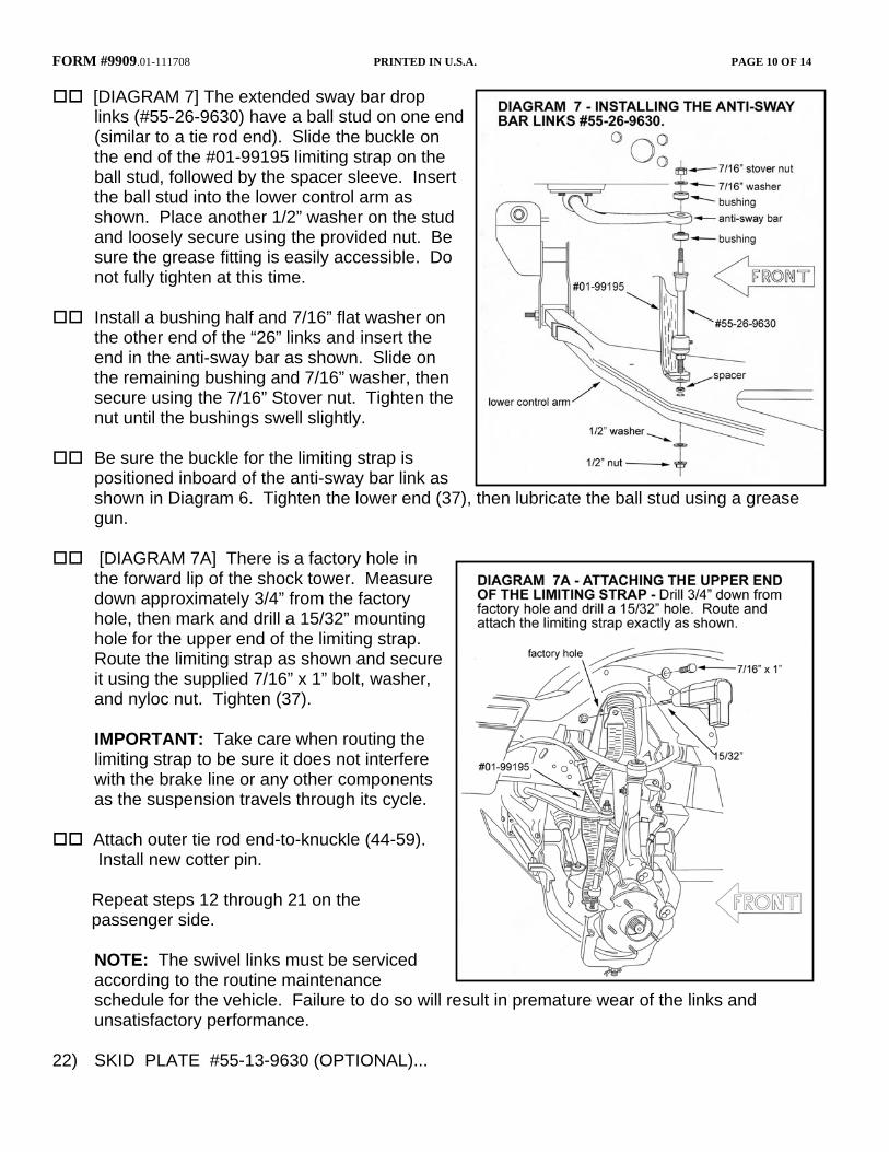
[DIAGRAM 7] The extended sway bar drop links (#55-26-9630) have a ball stud on one end (similar to a tie rod end). Slide the buckle on the end of the #01-99195 limiting strap on the ball stud, followed by the spacer sleeve. Insert the ball stud into the lower control arm as shown. Place another 1/2” washer on the stud and loosely secure using the provided nut. Be sure the grease fitting is easily accessible. Do not fully tighten at this time.
Install a bushing half and 7/16” flat washer on
the other end of the “26” links and insert the end in the anti-sway bar as shown. Slide on the remaining bushing and 7/16” washer, then secure using the 7/16” Stover nut. Tighten the nut until the bushings swell slightly.
Be sure the buckle for the limiting strap is
positioned inboard of the anti-sway bar link as shown in Diagram 6. Tighten the lower end (37), then lubricate the ball stud using a grease gun.
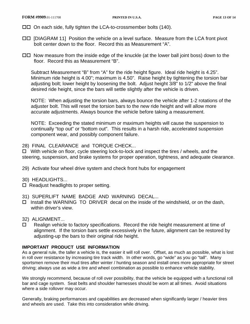
[DIAGRAM 7A] There is a factory hole in
the forward lip of the shock tower. Measure down approximately 3/4” from the factory hole, then mark and drill a 15/32” mounting hole for the upper end of the limiting strap. Route the limiting strap as shown and secure it using the supplied 7/16” x 1” bolt, washer, and nyloc nut. Tighten (37).
IMPORTANT: Take care when routing the
limiting strap to be sure it does not interfere with the brake line or any other components as the suspension travels through its cycle.
Attach outer tie rod end-to-knuckle (44-59).
Install new cotter pin.
Repeat steps 12 through 21 on the passenger side.
NOTE: The swivel links must be serviced
according to the routine maintenance schedule for the vehicle. Failure to do so will result in premature wear of the links and unsatisfactory performance.
22) SKID PLATE #55-13-9630 (OPTIONAL)...

FORM #9909.01-111708 PRINTED IN U.S.A. PAGE 11 OF 14
[DIAGRAM 8] Due to its size and weight, installing the plate is a 2-man job. Position plate and spacers, as shown, and install with 7/16” x 4” bolts / Nyloc nuts (37). Use furnished SAE flatwashers on both the bolt and nut sides.
23) TORSION BARS: #55-25-9630 DRIVER
SIDE TORSION BAR DROP BRACKET,
#55-24-9630 PASSENGER SIDE TORSION BAR DROP BRACKET;
#01-19960 TUBE of LOCTITE THREADLOCKER #242 Perform steps one side at a time, starting on the driver’s side.
The torsion bar adjusting bolts have
a factory applied thread sealant compound that must be removed prior to applying the Loctite Threadlocker. A wire wheel brush attachment on a bench grinder easily removes the old sealant. Clean the threads now, but do not apply the Threadlocker until just prior to reassembly.
[DIAGRAM 9] Bolt the “25” bracket
to the frame and crossmember, as shown. Where the bracket mates to the outboard face of the frame rail, use two of the factory bolts that were originally used on the adjuster arm cover plate (35-46). Use new 7/16” hardware where the “25” bracket mates to the crossmember (37).
Torsion bar - Match the alignment marks on the bar and LCA, then insert the bar into the
LCA.
NOTE: Be sure the torsion bars are reinstalled on the same side, and in the same front / rear orientation as they were removed.
At the bar’s front end, match the alignment marks on the bar and LCA, then insert the bar
into the LCA.
At the bar’s rear end, match the alignment marks on the bar and the adjuster arm.

FORM #9909.01-111708 PRINTED IN U.S.A. PAGE 12 OF 14
Insert the torsion bar insulator into the “25” bracket. Hold the torsion bar / adjuster arm against insulator, then position the puller tool.
Load the puller tool until the factory nut block can be inserted into the “25” bracket. NOTE:
Be sure the adjusting bolt seats properly into the adjuster arm recess. Apply a small amount of Threadlocker along the full length of the torsion bar adjusting bolt,
then thread the bolt approximately half way into the nut block. Now unload the puller tool.
Attach the factory adjuster arm cover plate to the “25” bracket. Use new 3/8” Nyloc nuts and flatwashers (13) at the two studs on the bracket’s outboard side. Reuse the factory cover plate bolts and nut clips, removed in Step 2, to attach the bottom end of the cover plate to the Superlift bracket (35-46).
24) TIRES / WHEELS...
[DIAGRAM 10] Tighten the lug nuts (100) in the sequence shown:
WARNING: When the tires / wheels are installed, always check for and remove any corrosion, dirt, or foreign material on the wheel mounting surface, or anything that contacts the wheel mounting surface (hub, rotor, etc.). Installing wheels without the proper metal-to metal contact at the wheel mounting surfaces can cause the lug nuts to loosen and the wheel to come off while the vehicle is in motion.
WARNING: Retighten lug nuts at 500 miles after any wheel change, or anytime the lug nuts are loosened. Failure to do so could cause wheels to come off while vehicle is in motion.
25) CLEARANCE CHECK...
With the vehicle still on jack stands, and the suspension “hanging” at full extension travel, cycle steering lock-to-lock and check all components for proper operation and clearances. Pay special attention to the clearance between the tires / wheels and brake hoses, wiring, etc.
Lower vehicle to the floor.
26) REAR LIFT...
The rear lift is purchased separately and has separate instructions. Install now.
27) ADJUSTING FRONT RIDE HEIGHT...
Manually bounce the front and rear of vehicle to normalize the torsion bars and leaf springs.
FORM #9909.01-111708 PRINTED IN U.S.A. PAGE 13 OF 14
On each side, fully tighten the LCA-to-crossmember bolts (140).
[DIAGRAM 11] Position the vehicle on a level surface. Measure from the LCA front pivot bolt center down to the floor. Record this as Measurement “A”.
Now measure from the inside edge of the knuckle (at the lower ball joint boss) down to the
floor. Record this as Measurement “B”.
Subtract Measurement “B” from “A” for the ride height figure. Ideal ride height is 4.25”. Minimum ride height is 4.00”; maximum is 4.50”. Raise height by tightening the torsion bar adjusting bolt; lower height by loosening the bolt. Adjust height 3/8” to 1/2” above the final desired ride height, since the bars will settle slightly after the vehicle is driven.
NOTE: When adjusting the torsion bars, always bounce the vehicle after 1-2 rotations of the
adjuster bolt. This will reset the torsion bars to the new ride height and will allow more accurate adjustments. Always bounce the vehicle before taking a measurement.
NOTE: Exceeding the stated minimum or maximum heights will cause the suspension to continually “top out” or “bottom out”. This results in a harsh ride, accelerated suspension component wear, and possibly component failure.
28) FINAL CLEARANCE and TORQUE CHECK...
With vehicle on floor, cycle steering lock-to-lock and inspect the tires / wheels, and the steering, suspension, and brake systems for proper operation, tightness, and adequate clearance.
29) Activate four wheel drive system and check front hubs for engagement
30) HEADLIGHTS...
Readjust headlights to proper setting.
31) SUPERLIFT NAME BADGE AND WARNING DECAL... Install the WARNING TO DRIVER decal on the inside of the windshield, or on the dash,
within driver’s view.
32) ALIGNMENT... Realign vehicle to factory specifications. Record the ride height measurement at time of
alignment. If the torsion bars settle excessively in the future, alignment can be restored by adjusting-up the bars to their original ride height.
IMPORTANT PRODUCT USE INFORMATION As a general rule, the taller a vehicle is, the easier it will roll over. Offset, as much as possible, what is lost in roll over resistance by increasing tire track width. In other words, go “wide” as you go “tall”. Many sportsmen remove their mud tires after winter / hunting season and install ones more appropriate for street driving; always use as wide a tire and wheel combination as possible to enhance vehicle stability. We strongly recommend, because of roll over possibility, that the vehicle be equipped with a functional roll bar and cage system. Seat belts and shoulder harnesses should be worn at all times. Avoid situations where a side rollover may occur. Generally, braking performances and capabilities are decreased when significantly larger / heavier tires and wheels are used. Take this into consideration while driving.

FORM #9909.01-111708 PRINTED IN U.S.A. PAGE 14 OF 14
Do not add, alter, or fabricate any factory or aftermarket parts to increase vehicle height over the intended height of the Superlift product purchased. Mixing component brands is not recommended. Most states have some type of law limiting vehicle height. The amount of lift allowed, and how the lift may be achieved, varies greatly. Several states offer exemptions for farm or commercially registered vehicles. It is the owner’s responsibility to check state and local laws to ensure that their vehicle will be in compliance. Superlift makes no claims regarding lifting devices and excludes any and all implied claims. Superlift will not be responsible for any altered product or any improper installation or use of our products. We will be happy to answer any questions concerning the design, function, and correct use of our products. IMPORTANT MAINTENANCE INFORMATION It is the ultimate buyer’s responsibility to have all bolts / nuts checked for tightness after the first 100 miles and then every 1000 miles. The steering, suspension and driveline systems, along with wheel alignment should be inspected by a qualified professional mechanic at least every 3000 miles. NOTICE TO DEALER AND VEHICLE OWNER Any vehicle equipped with a Superlift lifting device must have the enclosed “Warning to Driver” decal installed on the inside of the windshield or on the vehicle’s dash, within driver’s view. The “Warning to Driver” decal is to act as a constant safety reminder for whoever may be operating the vehicle. The WARRANTY IS VOID unless this decal is in place. INSTALLING DEALER... It is your responsibility to install warning decal and forward these installation instructions to the vehicle owner for review of warnings, product use and maintenance information. Replacement warning decals are available free upon request. These instructions are to be kept with the vehicle registration papers and owners manual for the service life of the vehicle. SUPERLIFT LIMITED LIFETIME WARRANTY Suspension products bearing the Superlift (LKI Ent.) name are warranted for as long as the original purchaser owns the vehicle that the LKI product was originally installed on. This warranty is non-transferable. Warranty covers only the product, no labor, time loss, or freight incurred. Any product that has been abused, altered, incorrectly installed, or used in competition is not covered. Product finish, spring bushings, Polyurethane products, and normal wear is not covered. The LKI product is subject to replacement or repair. No other warranties are expressed or implied. An authorized Superlift dealer must inspect the part in question and confirm that the “Warning to Driver” decal is properly displayed. A copy of the sales invoice is required for warranty consideration.