supernova airless paint sprayer
TRANSCRIPT
OWNER’S MANUAL820–008 Rev. MSUPERSEDES Rev. L
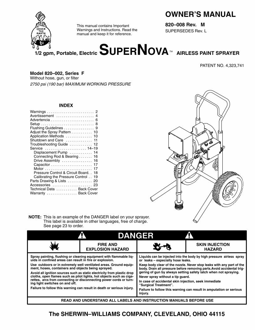
1/2 gpm, Portable, Electric SUPERNOVA� AIRLESS PAINT SPRAYER
PATENT NO. 4,323,741
Model 820–002, Series FWithout hose, gun, or filter
2750 psi (190 bar) MAXIMUM WORKING PRESSURE
INDEXWarnings 2. . . . . . . . . . . . . . . . . . . . . . . . . Avertissement 4. . . . . . . . . . . . . . . . . . . . Advertencia 6. . . . . . . . . . . . . . . . . . . . . . . Setup 8. . . . . . . . . . . . . . . . . . . . . . . . . . . . Flushing Guidelines 9. . . . . . . . . . . . . . . . Adjust the Spray Pattern 10. . . . . . . . . . . Application Methods 10. . . . . . . . . . . . . . Shutdown and Care 11. . . . . . . . . . . . . . Troubleshooting Guide 12. . . . . . . . . . . . Service 14–19. . . . . . . . . . . . . . . . . . . . . .
Displacement Pump 14. . . . . . . . . . . . Connecting Rod & Bearing 16. . . . . . . Drive Assembly 16. . . . . . . . . . . . . . . . Capacitor 17. . . . . . . . . . . . . . . . . . . . . . Motor 17. . . . . . . . . . . . . . . . . . . . . . . . . Pressure Control & Circuit Board. 18. Calibrating the Pressure Control 19. .
Parts Drawing & Lists 20. . . . . . . . . . . . . Accessories 23. . . . . . . . . . . . . . . . . . . . . Technical Data Back Cover. . . . . . . . . . . Warranty Back Cover. . . . . . . . . . . . . . . .
The SHERWIN–WILLIAMS COMPANY, CLEVELAND, OHIO 44115
This manual contains Important Warnings and Instructions. Read the manual and keep it for reference.
Liquids can be injected into the body by high pressure airless sprayor leaks – especially hose leaks.Keep body clear of the nozzle. Never stop leaks with any part of thebody. Drain all pressure before removing parts.Avoid accidental trig-gering of gun by always setting safety latch when not spraying.Never spray without a tip guard.In case of accidental skin injection, seek immediate“Surgical Treatment”.Failure to follow this warning can result in amputation or seriousinjury.
FIRE ANDEXPLOSION HAZARD
SKIN INJECTIONHAZARD
READ AND UNDERSTAND ALL LABELS AND INSTRUCTION MANUALS BEFORE USE
Spray painting, flushing or cleaning equipment with flammable liq-uids in confined areas can result in fire or explosion.Use outdoors or in extremely well ventilated areas. Ground equip-ment, hoses, containers and objects being sprayed.Avoid all ignition sources such as static electricity from plastic dropcloths, open flames such as pilot lights, hot objects such as ciga-rettes, arcs from connecting or disconnecting power cords or turn-ing light switches on and off.Failure to follow this warning can result in death or serious injury.
NOTE: This is an example of the DANGER label on your sprayer. This label is available in other languages, free of charge. See page 23 to order.
� �������
SAFETY WARNINGSHIGH PRESSURE SPRAY CAN CAUSE SERIOUS INJURY.
FOR PROFESSIONAL USE ONLY. OBSERVE ALL WARNINGS.Read and understand all instruction manuals before operating the equipment.
FLUID INJECTION HAZARDGeneral SafetyThis equipment generates very high fluid pressure. Spray fromthe gun, leaks or ruptured components can inject fluid throughyour skin and into your body, and cause extremely serious bodilyinjury, including the need for amputation. Also, fluid injected orsplashed into the eyes or on the skin can cause serious damage.NEVER point the spray gun at any one or at any part of the body.NEVER put your hand or fingers over the spray tip. NEVER tryto “blow back” paint; this is NOT an air spray system.ALWAYS have the tip guard in place on the spray gun whenspraying.ALWAYS follow the PRESSURE RELIEF PROCEDURE, below,before cleaning or removing the spray tip or servicing any sys-tem equipment.NEVER try to stop or deflect leaks with your hand or body.Be sure equipment safety devices are operating properly beforeeach use.
Medical Alert––Airless Spray WoundsIf any fluid appears to penetrate your skin, get EMERGENCYMEDICAL CARE AT ONCE. DO NOT TREA T AS A SIMPLECUT. Tell the doctor exactly what fluid was injected.
Note to Physician: Injection in the skin is a traumatic injury. Itis important to treat the injury surgically as soon as possible.Do not delay treatment to research toxicity . Toxicity is aconcern with some exotic coatings injected directly into theblood stream. Consultation with a plastic surgeon or reconstru-ctive hand surgeon may be advisable.
Spray Gun Safety DevicesBe sure all gun safety devices are operating properly beforeeach use. Do not remove or modify any part of the gun; this cancause a malfunction and result in serious bodily injury.
Safety LatchWhenever you stop spraying, even for a moment, always set thegun safety latch in the closed or “safe” position, making the guninoperative. Failure to set the safety latch can result in accidentaltriggering of the gun.
DiffuserThe gun diffuser breaks up spray and reduces the risk of fluid in-jection when the tip is not installed. Check dif fuser operationregularly. Follow the PRESSURE RELIEF PROCEDURE , be-low, then remove the spray tip. Aim the gun into a metal pail, hold-ing the gun firmly to the pail. Using the lowest possible pressure,trigger the gun. If the fluid emitted is not diffused into an irregularstream, replace the diffuser immediately.
Tip GuardALWAYS have the tip guard in place on the spray gun whilespraying. The tip guard alerts you to the fluid injection hazardand helps reduce, but does not prevent, the risk of accidentallyplacing your fingers or any part of your body close to the spraytip.
Trigger GuardAlways have the trigger guard in place on the gun when sprayingto reduce the risk of accidentally triggering the gun if it is droppedor bumped.
Spray Tip SafetyUse extreme caution when cleaning or changing spray tips. If thespray tip clogs while spraying, engage the gun safety latch im-mediately. ALWAYS follow the PRESSURE RELIEF PROCE-DURE, below, and then remove the spray tip to clean it.
NEVER wipe off build–up around the spray tip until the pressureis fully relieves and the gun safety is engaged.
PRESSURE RELIEF PROCEDURE
To reduce the risk of serious bodily injury, including fluid injection,splashing fluid or solvent in the eyes or on the skin, or injury frommoving parts or electric shock, always follow this procedurewhenever you shut off the sprayer, when checking or servicingany part of the spray system, when installing, cleaning or chang-ing spray tips, and whenever you stop spraying.
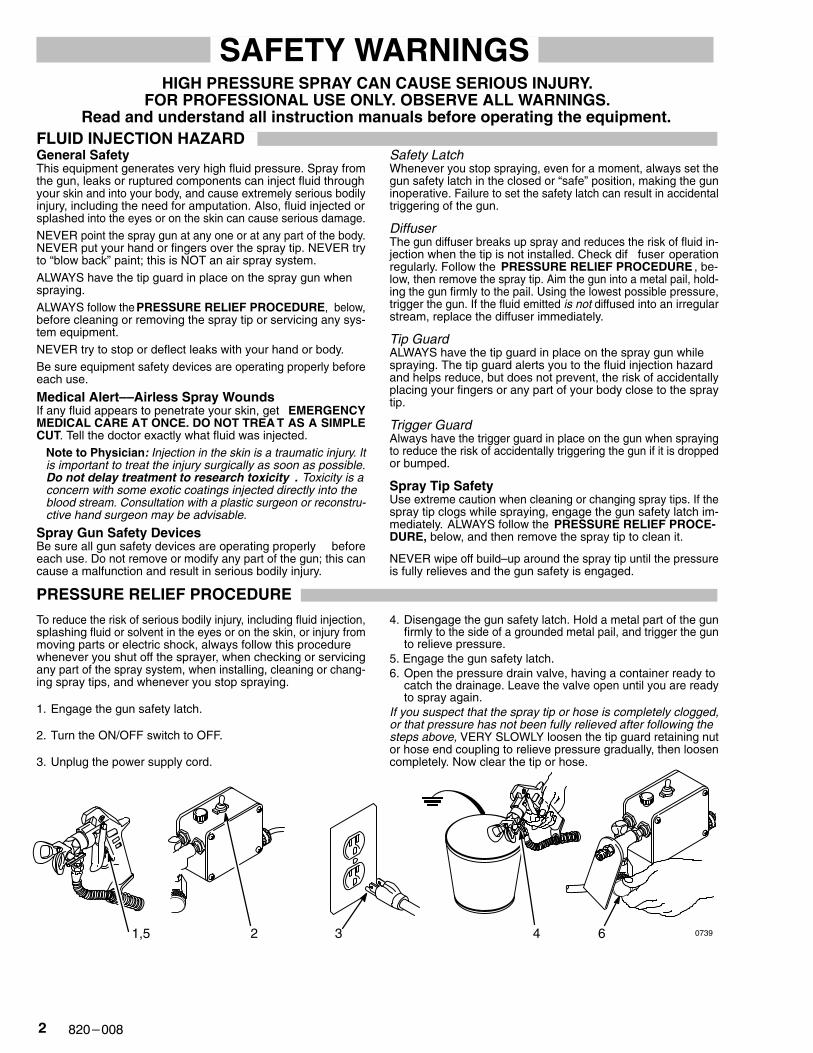
1. Engage the gun safety latch.
2. Turn the ON/OFF switch to OFF.
3. Unplug the power supply cord.
4. Disengage the gun safety latch. Hold a metal part of the gunfirmly to the side of a grounded metal pail, and trigger the gunto relieve pressure.
5. Engage the gun safety latch.6. Open the pressure drain valve, having a container ready to
catch the drainage. Leave the valve open until you are readyto spray again.
If you suspect that the spray tip or hose is completely clogged,or that pressure has not been fully relieved after following thesteps above, VERY SLOWLY loosen the tip guard retaining nutor hose end coupling to relieve pressure gradually, then loosencompletely. Now clear the tip or hose.
1,5 2 3 4 6 0739
��������
MOVING PARTS HAZARDMoving parts can pinch or amputate your fingers or other bodyparts. KEEP CLEAR of moving parts when starting or operatingthe sprayer. Follow the Pressure Relief Procedure on page 2before checking or servicing any part of the sprayer, to preventit from starting accidentally.
EQUIPMENT MISUSE HAZARDGeneral SafetyAny misuse of the spray equipment or accessories, such asoverpressurizing, modifying parts, using incompatible chemi-cals and fluids, or using worn or damaged parts, can cause themto rupture and result in fluid injection, splashing in the eyes or onthe skin, or other serious bodily injury, or fire, explosion or prop-erty damage.
NEVER alter or modify any part of this equipment; doing so couldcause it to malfunction.
CHECK all spray equipment regularly and repair or replace wornor damaged parts immediately.
Always wear protective eyewear, gloves, clothing and respiratoras recommended by the fluid and solvent manufacturer.
System PressureThis sprayer can develop 2750 psi (190 bar) MAXIMUM WORK-ING PRESSURE. Be sure all spray equipment and accessoriesused are rated to withstand the this pressure. DO NOT exceedthe maximum working pressure of any component or accessoryused in the system.
Fluid and Solvent CompatibilityAll chemicals used in the sprayer must be chemically compatiblewith the wetted parts shown in the TECHNICAL DATA on page24. Consult your chemical supplier to ensure compatibility.
Do not use 1,1,1-trichloroethane, methylene chloride, other ha-logenated hydrocarbon solvents or fluids containing such sol-vents in this equipment, which contains aluminum and/or zincparts. Such use could result in a serious chemical reaction, withthe possibility of explosion, which could cause death, seriousbodily injury and/or substantial property damage.
HOSE SAFETY
High pressure fluid in the hoses can be very dangerous. If thehose develops a leak, split or rupture due to any kind of wear ,damage or misuse, the high pressure spray emitted from it cancause a fluid injection injury or other serious bodily injury or prop-erty damage.
ALL FLUID HOSES MUST HAVE STRAIN RELIEFS ON BOTHENDS! The strain reliefs help protect the hose from kinks or bendsat or close to the coupling which can result in hose rupture.
TIGHTEN all fluid connections securely before each use. Highpressure fluid can dislodge a loose coupling or allow high pres-sure spray to be emitted from the coupling.
NEVER use a damaged hose. Before each use, check the entirehose for cuts, leaks, abrasion, bulging cover, or damage ormovement of the hose couplings. If any of these conditions exist,replace the hose immediately. DO NOT try to recouple high pres-sure hose or mend it with tape or any other device. A repairedhose cannot contain the high pressure fluid.
HANDLE AND ROUTE HOSES CAREFULL Y. Do not pull onhoses to move equipment. Keep hoses clear of moving partsand hot surfaces of the pump and gas engine. Do not use fluidsor solvents which are not compatible with the inner tube andcover of the hose. DO NOT expose Graco hoses to tempera-tures above 180� F (82� C) or below –40� F (–40� C).
Hose Grounding ContinuityProper hose grounding continuity is essential to maintaining agrounded spray system. Check the electrical resistance of yourfluid hoses at least once a week. If your hose does not have atag on it which specifies the maximum electrical resistance, con-tact the hose supplier or manufacturer for the maximum resis-tance limits. Use a resistance meter in the appropriate range foryour hose to check the resistance. If the resistance exceeds therecommended limits, replace it immediately. An ungrounded orpoorly grounded hose can make your system hazardous. Alsoread FIRE OR EXPLOSION HAZARD, below.
FIRE OR EXPLOSION HAZARD
Static electricity is created by the flow of fluid through the pumpand hose. If every part of the spray equipment is not properlygrounded, sparking may occur, and the system may become haz-ardous. Sparking may also occur when plugging in or unplugginga power supply cord or using a gasoline engine. Sparks can ignitefumes from solvents and the fluid being sprayed, dust particlesand other flammable substances, whether you are spraying in-doors or outdoors, and can cause a fire or explosion and seriousbodily injury and property damage.
If you experience any static sparking or even a slight shock whileusing this equipment, STOP SPRAYING IMMEDIATELY. Checkthe entire system for proper grounding. Do not use the systemagain until the problem has been identified and corrected.
GroundingTo reduce the risk of static sparking, ground the sprayer and allother spray equipment used or located in the spray area.CHECK your local electrical code for detailed grounding instruc-tions for your area and type of equipment. BE SURE to groundall of this spray equipment:
1. Sprayer:plug the power supply cord, or extension cord, eachequipped with an undamaged three-prong plug, into a proper-ly grounded outlet. Do not use an adapater . All extensionscords must have three wires and be rated for 15 amps.
2. Fluid hoses: use only grounded hoses with a maximum � �f 500ft (150 m) combined hose length to ensure grounding continu-ity. See Hose Grounding Continuity above.
3. Spray gun: obtain grounding through connection to a properlygrounded fluid hose and sprayer.
4. Object being sprayed: according to local code.
5. Fluid supply container: according to local code.
6. All solvent pails used when flushing, according to local code.Use only metal pails, which are conductive. Do not place thepail on a non–conductive surface, such as paper or card-board, which interrupts the grounding continuity.
7. To maintain grounding continuity when flushing or relievingpressure, always hold a metal part of the gun firmly to the sideof a grounded metal pail, then trigger the gun.
Flushing SafetyReduce the risk of fluid injection injury, static sparking, or splash-ing by following the flushing procedure given on page 9 of thismanual. Follow the PRESSURE RELIEF PROCEDURE onpage 2, and remove the spray tip before flushing. Hold a metalpart of the gun firmly to the side of a grounded metal pail and usethe lowest possible fluid pressure during flushing.
IMPORTANT
United States Government safety standards have been adopted under the Occupational Safety and Health Act. These standards –particularly the General Standards, Part 1910, and the Construction Standards, Part 1926 – should be consulted.
� �������
AVERTISSEMENTLa pulvérisation à haute pression peut causer de blessures très graves.
Réservé exclusivement à l’usage professionnel. Observer toutes les consignes de sécurité. Bien lire et bien comprendre tous les manuels d’instructions avant d’utiliser le matériel.
RISQUES D’INJECTIONConsignes générales de sécuritéCet appareil produit un fluide à très haute pression. Le fluide pul-vérisé par le pistolet ou le fluide sous pression provenant de fuitesou de ruptures peut pénétrer sou la peau ou à l’intérieur du corpset entraîner des blessures très graves, voir même une amputa-tion. Même sans être sous pression, le fluide éclaboussant ouentrant dans les yeux peut aussi entraîner des blessures graves.NE JAMAIS pointer le pistolet vers quelqu’un ou vers une partiequelconque du corps. NE JAMAIS mettre le main ou les doigtssur l’ajutage du pulvérisateur. NE JAMAIS essayer de “refouler”la peinture. Cet appareil N’est P AS un compresseurpneumatique.TOUJOURS garder la protection de l’ajutage en place sure lepistolet pendant la pulvérisation.TOUJOURS observer la Marche à Suivre Pour Détendre laPression donnée plus loin, avant de nettoyer ou d’enlever l’aju-tage du pulvérisateur, ou d’effectuer un travail quelconque surune partie de l’appareil.NE JAMAIS essayer d’arrêter ou de dévier le fuites avec la mainou le corps.Avant chaque utilisation, bien s’assurer que les dispositifs de sé-curité fonctionnent correctement.Soins médicauxEn cas de pénétration de fluide sous la peau: DEMANDER IM-MEDIATEMENT DES SOINS MÉDICAUX D’URGENCE. NEPAS SOIGNER CETTE BLESSURE COMME UNE SIMPLECOUPURE.
Avis au médecin: La pénétration des fluides sous la peau estun traumatisme. Il est important de traiter chirurgicalementcette blessure immédiatement. Ne pas retarder le traite-ment pour effectuer des recherches sur la toxicité. Certains re-vêtements exotiques sont dangereusement toxiques quandils sont injectés directement dans le sang. Il est souhaitable deconsulter un chirurgien esthétiques ou un chirurgien spéciali-sé dans la reconstruction des mains.
Dispositifs de sécurité du pistoletAvant chaque utilisation, bien s’assure que tous les dispositifsde sécurité du pistolet fonctionnent correctement. Ne pas enle-ver ni modifier une partie quelconque du pistolet; ceci risqueraitd’entraîner un mauvais fonctionnement et des blessures gra-ves.
Verrou de sécuritéA chaque fois que l’on s’arrête de pulvériser , même s’il s’agitd’un court instant, toujours mettre le verrou de sécurité du pisto-let sur la position, “fermée” ou “sécurité” (“safe”), pour empêcherle pistolet de fonctionner. Si le verrou de sécurité n’est pas mis,le pistolet peut se déclencher accidentellement.
DiffuseurLe diffuseur du pistolet sert à diviser le jet et à réduire les risquesd’injection accidentelle quand l’ajutage n’est pas en place. Véri-fier le fonctionnement du diffuseur régulièrement. Pour cette vé-rification, détendre la pression en observant la Marche à SuivrePour Détendre la Pression donnée plus loin enlever l’ajutagedu pulvérisateur. Pointer le pistolet dans un seau en métal, en lemaintenant fermement contre le seau. puis, en utilisant la pres-sion la plus faible possible, appuyer sur la gâchette du pistolet.Si le fluide projeté n’est pas diffusé sous forme de jet irrégulier,remplacer immédiatement le diffuseur.
Protection de l’ajutageTOUJOURS maintenir la protection de l’ajutage en place sur lepistolet du pulvérisateur pendant la pulvérisation. La protectionde l’ajutage attire l’attention sur les risques d’injection let contri-bue à réduire, mai n’évite pas le risque, que les doigts ou unepartie quelconque du corps ne passent accidentellement àproximité immédiate de l’ajutage du pulvérisateur.
Consignes de sécurité concernant l’ajutagedu pulvérisateurFaire extrêmement attention à l’occasion du nettoyage ou dueremplacement des ajutages du pulvérisateur . Si l’ajutage sebouche pendent la pulvérisation, mettre immédiatement le ver-rou de sécurité du pistolet. TOUJOURS bien observe la Marcheà Suivre Pour Détendre la Pression puis enlever l’ajutage dupulvérisateur pour le nettoyer.NE JAMAIS essuyer ce qui s’est accumulé autour de l’ajutagedu pulvérisateur avant que la pression ne soit complètementtombée et que le verrou de sécurité du pistolet ne soit engagé.
MARCHE À SUIVRE POUR DÉTENDRE LA PRESSIONPour réduire les risques de blessures graves, y compris les bles-sures par projection de fluide ou celles causées par de éclabous-sures dans les yeux ou sur la peau, par des pièces en mouve-ment, toujours bien observe cette marche à suivre chaque foisque l’on arrête le pulvérisateur, à l’occasion de la vérification, duègale ou du nettoyage du système ou lors du changement desajutages.
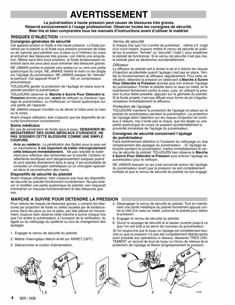
1. Engager le verrou de sécurité du pistolet.
2. Mettre l’interrupteur March-Arrêt sur ARRET (OFF).
3. Debracncher le cordon d’alimentation.
4. Désengager le verrou de sécurité du pistolet. Tout en mainte-nant une partie métallique du pistolet fermement appuyé con-tre le côte d’un seau en métal, actionner le pistolet pour libérerla pression.
5. Engager le verrou de sécurité du pistolet.6. Ouvrir la soupape de sécurité et la laisser ouverte jusqu’à ce
que l’on soit prêt à se servir de nouveau du pulvérisateur.Si l’on soupconne que le tuyau ou l’ajutage est complètement bou-ché ou que la pression n’a pas été complètement libérée aprèsavoir procédé aux opérations ci–dessus, desserrer TRES LEN-TEMENT un raccord de bout de tuyau ou l’écrou de retenue de laprotection de l’ajutage et libérer progressivement la pression.
1,5 2 3 4 6 0739
��������
RISQUES EN CAS DE MAUVAISE UTILISATION DU MATERIAL
Consignes générales de sécuritétoute utilisation anormale de l’appareil du pulvérisation ou desaccessoires comme, par exemple, la mise sous une pressionexcessive, les modifications de pièces, l’utilisation de produitschimiques et de matières incompatibles et l’utilisation de piècesusées ou abîmées peut causer des dégâts à l’appareil ou desruptures de pièces et entraîner une injection de liquide ou d‘au-tres blessures sérieuses, un incendie, une explosion ou d’autresdégâts.
Toujours porter une protection pour les yeux, de gants, des vête-ments protecteur et un dispositif pour la respiration correspon-dant aux recommandations des fabricants de fluides et solvants.
PressionCe pulvérisateur peut produire une PRESSION MAXIMUM DETRAVAIL 190 bar (2750 lb/po.�) S’assurer que tous les élémentsdu pulvérisateur et ses accessoires sont conçus pour résister àla pression maximum de travail de ce pulvérisateur. NE PAS dé-passer la pression maximum de travail d’aucun des éléments ouaccessoires utilisés avec cet appareil.
Compatibilité chimique des corpsBIEN S’ASSURER que tous les corps des solvants utilisés sontchimiquement compatibles avec les parties mouillées indiquéesdans les “Données techniques”, à la page 24. Toujours lire soi-gneusement les documents et brochures du fabricant des flui-des et solvants utilisés avant de s’en servir dans ce pulvérisa-teur.
Le fluide à haute pression circulant dans les tuyaux peut être trèsdangereux. En cas de fuite sur le tuyau, de fissure, déchirure ourupture à la suite de l’usure, de dégâts ou d’une mauvaise utilisa-tion, les projections de fluide haute pression qui en proviennentpeuvent entraîner des blessures graves par pénétration sous lapeau ou par contact, ainsi que des dégâts matériels.
TOUS LES TUYAUX FLEXIBLES DOIVENT AVOIR DES RES-SORTS SPIRALE DE PROTECTION AUX 2 BOUTS! Les spira-les de protection contribuent à éviter la formation de pliures, deboucles ou de nœuds sur les tuyaux qui pourraient entraîner larupture du tuyau à l’endroit du raccord ou à son voisinage.
SERRER FERMEMENT tous les raccords avant chaque utilisa-tion. Le fluide sous pression peut faire sauter un raccord desser-ré ou produire un jet à haute pression s’échappant par le rac-cord.
NE JAMAIS utiliser un tuyau endommagé. NE PAS essayer derefaire le raccord d’un tuyau haute pression ni de réparer letuyau avec du ruban adhésif ou par tout autre moyen. Un tuyauréparé ne peut pas résister au fluide sous pression.
MANIPULER LES TUYAUX AVEC PRECAUTION ET CHOISIRSOIGNEUSEMENT LEUR CHEMIN. Ne pas déplacer le fluideen tirant sur le tuyau. Ne pas utiliser de fluides ou de solvantsque ne sont pas compatibles avec l’enveloppe intérieur ou exté-rieure de tuyau. NE PAS exposer le tuyau à fluides des tempéra-tures supérieures à 82 �C (180 �F) ou inférieures à –40�C(–40�F).
Continuité de la mise à la terre des tuyauxUne bonne continuité de la mise à la terre des tuyaux est essen-tielle pour maintenir la mise à la terre de l’ensemble de vaporisa-tion. Vérifiez la résistance électrique de vos tuyaux à fluides età air, au moines une fois par semaine. Si votre tuyau ne compor-te pas d’étiquette qui précise la résistance électrique maximum,prenez contact avec le fournisseur de tuyaux ou la fabricant pouravoir les limites de résistance maximum. Utilisez un mètre de ré-sistance de la gamme appropriée pour votre tuyau et vérifiez larésistance. Si celle–ci dépasse les limites recommandées, rem-placez le tuyau immédiatement. Un tuyau sans mise à la terre ouavec une mise à la terre incorrecte peut entraîner des risquespour votre système. Lisez aussi LES RISQUES D’INCENDIEOU D’EXPLOSION.
RISQUES D’INCENDIE OU D’EXPLOSION
De l’électricité statique est produite par le passage du fluide àgrande vitesse dans la pompe et dans les tuyaux. Si toutes lespièces de l’appareil de pulvérisation ne sont pas convenable-ment reliées ou à la masse ou à la terre, des étincelles peuventse produire et l’appareil risques d’être dangereux. Des étincellespeuvent Également se produire à l’occasion du branchement oudu débranchement du cordon d’alimentation ou de l’utilisationd’un moteur à essence. Les étincelles sont suffisantes pour allu-mer les vapeurs de solvants et le fluide pulvérisé, les fines parti-cules de poussière ainsi que d’autres substances inflammables,quand on pulvérisé à l’intérieur ou à l’extérieur, et elles peuventcauser un incendie ou une explosion, ainsi que des blessuresgraves et des dégâts matériels.S’il se produit des étincelles d’électricité statique, ou si vous res-sentez la moindre décharge, ARRETEZ IMMEDIATEMENT LAPULVERISATION. Vérifiez que le système avant que le problèmesoit identifié et corrigé.Mise à la terre ou à la massePour réduire les risques de production d’étincelles d’électricitéstatique, le pulvérisateur et tous les équipement utilisés ou setrouvant dans la zone de pulvérisation doivent être reliés à la ter-re ou à la masse. Pour connaître le détail des instructions demise à la terre dans la région et le type particulier d’équipement,CONSULTER le code ou les réglementations électriques loca-les. S’ASSURER que tous le équipements de pulvérisation sui-vants sont bien reliés à la terre:1. Pulvérisateur: Brancher le cordon d’alimentation ou la
rallonge qui doivent être équipés d’une prise à 3 fiches en bonétat, dans une prise de courant convenablement mise à laterre. Ne pas utiliser d‘adapteur. Toutes les rallonges doiventavoid 3 fils et être prévues pour 15 ampères.
2. Pistolet:Réaliser la mise à la terre en le raccordant à unetuyau flexible et à une pulvérisateur déjà convenablement re-liés à la terre.
3. Tuyaux flexibles: Afin d’assurer la continuité de la mise à laterre, n’utiliser que des tuyaux comportant une mise à la terreet ayant une longueur maximum combinée de 150 m (1500pieds). Se reporter également au paragraphe, “Continuitédu circuit de mis à la terre des tuyaux”.
4. Récipient d’alimentation: observer le code ou les réglementa-tions locales.
5. Objets, matériel ou surfaces recevant la pulvérisation: obser-ver le code ou les réglementations locales.
6. Tous le seaux de solvant utilisés pour le rinçage: observer lecode ou les réglementations locales. N’utiliser que des seauxmétallique conducteurs de l’électricité. Ne pas mettre le seausur une surface non conductrice comme sur du papier ou ducarton car cela interromprait la continuité de la mise à la terre.
7. Pour conserver la continuité de la mise à la terre quand on rin-cé le matériel ou quand on libère la pression, toujours mainte-nir une partie métallique du pistolet fermement appuyée con-tre le côté d’un seau en métal puis appuyer sur la détente dupistolet.
Mesures de Sécurité concernant le RinçagePour réduire les risques de blessures par pénétration de la peauet les risques dûs aux étincelles d’électricité statique ou auxéclaboussures, observe la marche à suivre pour le rinçage don-née à la page 9 de ce manuel.
NE JAMAIS faire tourner un moteur dans un bâtiment fermé àmoins que les gaz d’échappement ne soient dirigés au dehors.Les gaz d’échappement contiennent de l’oxyde de carbone, ungaz toxique, inodore et invisible qui peut entraîner des malaisesgraves ou même la mort se l’on le respiré.
� �������
ADVERTENCIAEL ROCIADO A ALTA PRESION PUEDE CAUSAR GRAVES LESIONES.
SOLO PARA USO PROFESIONAL. RESPECTE LOS AVISOS DE ADVERTENCIA. Lea y entienda todo el manual de instrucciones antes de manejar el equipo.
PELIGRO DE INYECCION DE FLUIDOSeguridad generalEste equipo general un fluido a una presión muy alta. El rociadode la pistola, los escapes de fluido o roturas de los componentespueden inyectar fluido en la piel y el cuerpo y causar lesionesextremadamente graves, incluyendo a veces la necesidad deamputación. También, el fluido inyectado o salpicado en los ojospuede causar graves daños.
NUNCA apuntar la pistola hacia alguien o alguna parte del cuer-po. NUNCA colocar la mano o los dedos encima de la boquilla.NUNCA tratar de “hacer retornar la pintura”; este NO es un siste-ma de rociado de aire.
SIEMPRE tener colocado el protector de la boquilla en la pistolamientras se está pulverizando.
SIEMPRE seguir el procedimiento de descarga de presión,dado más abajo, antes de limpiar o sacar la boquilla o de dar ser-vicio a cualquier del sistema.
NUNCA tratar de parar o desviar los escapes con la mano o elcuerpo.
Asegurar que todos los aparatos de seguridad del equipo estánfuncionando bien antes de cada uso.
Tratamiento médicoSi pareciera que un poco de fluido penetró la piel, conseguirTRATAMIENTO MEDICO DE URGENCIA DE INMEDIATO. NOTRATAR LA HERIDA COMO UN SIMPLE CORTE. Decir al mé-dico exactamente cua fluido fue.
Aviso al médico: Si se llega a inyectar este fluido en la piel secausa una lesión traumática. Es importante tratar quirúrgi-camente la lesión a la brevedad posible. No demorar el tra-tamiento para investigar la toxicidad. La toxicidad es algo desumar importancia en algunas pinturas exóticas cuando se in-yectan directamente al torrente sanguíneo. Sirá convenienteconsultar a un especialista en cirugía plástica o reconstructivade las manos.
Aparatos de seguridad de la pistola pulverizadoraAsegurar que todos los aparatos protectores de la pistola estánfuncionando bien antes de cada uso. No sacar ni modificar nin-guna pieza de la pistola pues podría causar el malfuncionamien-to de la misma con las consiguientes lesiones personales.
Pestillo de seguridadCada vez que se deje de pulverizar, aunque sea por un brevemomento, siempre colocar el pestillo de seguridad en la posi-ción “cerrada”, lo que deja la pistola inoperante. El no hacerlopuede llevar al disparo imprevisto de la pistola.
DifusorEl difusor de la pistola dispersa el chorro pulverizado y reduceel riesgo de inyección cuando no está instalada la boquilla. Revi-sar con regularidad el funcionamiento del difusor. Seguir el pro-cedimiento de descarga de presión, dado más abajo, y des-pués sacar la boquilla. Apuntar la pistola a un balde metálico,sosteniéndola bien firme contra él. Utilizando la presión más ba-jo posible, disparar la pistola. Si el fluido emitido no sale dispersoen un chorro irregular, reemplazar de inmediato el difusor.
Protector de la boquillaSIEMPRE tener el protector de la boquilla colocado en la pistolamientras se está pulverizando. Este protector llama la atencióncontra el peligro de inyección y ayuda a reducir, pero no evita,la colocación accidental de los dedos o cualquier otra parte delcuerpo cerca de la boquilla.
Seguridad de la boquilla pulverizadoraTener mucho cuidado al limpiar o cambiar las boquillas. Si llega-ra a obstruirse mientras está pulverizando, enganchar el pestillode la pistola de inmediato. SIEMPRE seguir el procedimientode descarga de presión y después sacar la boquilla paralimpiarla
NUNCA limpiar la acumulación de pintura alrededor de la boqui-lla antes de que se haya descargado por completo la presión yel pestillo esté enganchado.
PROCEDIMIENTO DE DESCARGA DE PRESION
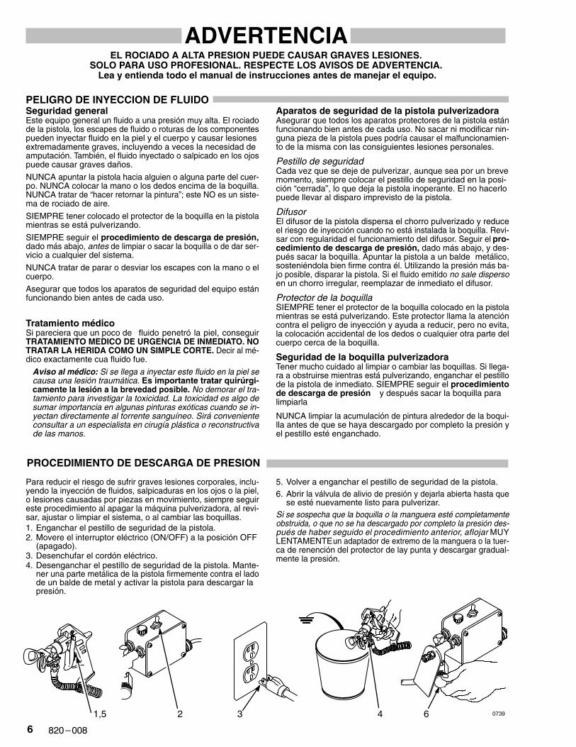
Para reducir el riesgo de sufrir graves lesiones corporales, inclu-yendo la inyección de fluidos, salpicaduras en los ojos o la piel,o lesiones causadas por piezas en movimiento, siempre seguireste procedimiento al apagar la máquina pulverizadora, al revi-sar, ajustar o limpiar el sistema, o al cambiar las boquillas.1. Enganchar el pestillo de seguridad de la pistola.2. Movere el interruptor eléctrico (ON/OFF) a la posición OFF
(apagado).3. Desenchufar el cordón eléctrico.4. Desenganchar el pestillo de seguridad de la pistola. Mante-
ner una parte metálica de la pistola firmemente contra el ladode un balde de metal y activar la pistola para descargar lapresión.
5. Volver a enganchar el pestillo de seguridad de la pistola.6. Abrir la válvula de alivio de presión y dejarla abierta hasta que
se esté nuevamente listo para pulverizar.Si se sospecha que la boquilla o la manguera esté completamenteobstruida, o que no se ha descargado por completo la presión des-pués de haber seguido el procedimiento anterior, aflojar MUYLENTAMENTE un adaptador de extremo de la manguera o la tuer-ca de renención del protector de lay punta y descargar gradual-mente la presión.
1,5 2 3 4 6 0739
��������
PELIGRO POR MAL USO DEL EQUIPOSeguridad generalCualquier mal uso del equipo pulverizador o los accesorios, talcomo sobre presurización, modificación de piezas, uso de ma-teriales y productos químicos incompatibles, o utilización de pie-zas dañadas o desgastadas, puede hacen que se rompan ycausen la inyección de fluido u otras lesiones corporales graves,incendio, explosión o daños a la propiedad.Siempre usar gafas, guantes, vestimentas protectoras y un res-piradero, tal como recomiendan los fabricantes del fluido y delsolvente.
Presión del sistemaEsta pulverizadora puede desarrollar 190 barías (2750 psi) dePRESION DE TRABAJO MAXIMA. Asegurar que todo el equipopulverizador y sus accesorios tienen la capacidad para aguan-tar la presión máxima de trabajo de ningún componente o acce-sorio de este sistema.
Compatibilidad de fluidoSiempre leer las instrucciones del fabricante del fluido y solven-te antes de usarlos en esta pulverizadora.
SEGURIDAD EN EL USO DE LAS MANGUERAS
El fluido que escapa a alta presión por las mangueras puede sermuy peligroso. Si en la manguera se desarrola un escape, unarotura o rajadura debido a cualquier tipo de desgaste, daño omaltrato, el chorro a alta presión emitido por allí puede causaruna lesión por inyección u otras lesiones corporales graves odaños a la propiedad.¡TODAS LAS MANGUERAS PARA FLUIDOS TIENEN QUETENER GUARDAS DE RESORTE EN AMBOS EXTREMOS!Estas protegen las mangueras contra dobleces o retorcedurasen los acoplamientos o cerca de ellos, los que podrían traducir-se en roturas de la manguera.Antes de usarlas, APRETAR bien firmes todas las conexiones.El fluido a lata presión puede desalojar un acoplamiento sueltoo dejar que pro él escape un chorro a alta presión.NUNCA usar una manguera que está dañada. Siempre revisarlaen busca de cortaduras, escapes, abrasión, cubierta abultada, oacoplamientos sueltos o dañados. Si llegara a encontrarse cual-quiera de estas condiciones, reemplazar de inmediato la mangue-ra. NO intentar reacoplar una manguera de alta presión o enmen-darla con cinta adhesiva u otro material similar. Una manguera queha sido remendada no aguante el fluido al alta presión.
MANEJAR Y P ASAR CUIDADOSAMENTE LAS MANGUE-RAS. No tirar de las mangueras para mover el equipo. No usarfluidos o solventes que sean incompatibles con el tubo internoy la cubierta de la manguera. NO exponer las mangueras a tem-peraturas sobre 82�� C (180�F) o bajo -40�C (-40� F).
Continuidad del circuito de puesta a tierrade la mangueraLa continuidad del circuito de puesta a tierra apropiado es esen-cial para mantener conectado a tierra el sistema pulverizador.Es indispensable revisar la resistencia eléctrica máxima de lasmangueras de aire y de fluido por lo menos una vez a la semana.Si la manguera no tiene una etiqueta en la cual se especifica laresistencia eléctrica máximum, ponerse en contacto con el pro-veedor o fabricante de la manguera para la información sobrelos límites de resistencia. Usar un metro de resistencia en la ga-ma apropiada para comprobar la resistencia; si excede los litesrecomendados, reemplazarla de inmediato. Es muy arriesgadotener una manguera sin puesta a tierra o con la puesta a tierraen malas condiciones. Leer también la información sobre RIES-GO DE INCENDIO O EXPLOSION, más arriba.
PELIGRO DE INCENDIO O EXPLOSION
El flujo a alta velocidad del fluido al pasar por la bomba y mangue-ra crea electricidad estática. Si todas las partes del equipo pulve-rizador no tienen buena tierra, pueden ocurrir chispas, convirtién-do al sistema en algo peligroso. T ambién, pueden producirsechispas al enchufar o desenchufar el cordón eléctrico o al usarun motor de gasolina. Estas chispas pueden inflamar los vaporesde los solventes y el chorro de fluido pulverizado, partículas depolvo y otras sustancias inflamables, sea al aire libre o bajo techo,lo que podría causar una explosión o incendio y graves lesionescorporales y daños a la propiedad.Si ocurre una chispa de electricidad estática o incluso un ligerochoque eléctrico mientras se usa el equipo, DEJAR DE PULVE-RIZAR DE INMEDIATO. Revisar todo el sistema en busca de unatierra apropiado. No usar de nuevo el sistema hasta haber identifi-cado y solucionado el problema.
Puesta a tierraPara reducir el riesgo de chispas estáticas, conectar a tierra lapulverizadora y todo el otro equipo de pulverizar que se use ose encuentre en el lugar que se va a rociar. CONSULTAR el códi-go eléctrico de la localidad para las instrucciones sobre las co-nexiones a tierra exigidas para la zona y tipo de equipo. ASEGU-RAR de conectar a tierra todo este equipo pulverizador:1. Pulverizadora:enchufar el cordón eléctrico, o cable extensor,
cada uno con un enchuf de tres patas en buen estado, a untomacorriente con puesta a tierra aporpiado. No usar unadaptador. Totos los cables extensores tienen que tener treshilos y una capacidad de 15 amperios.
2. Mangueras para fluidos: usar solamente mangueras conpuesta a tierra de una longitud combinada de 150 m (500pies), para asegurar buena continuidad a tierra. Referirsetambién al párrafo sobre continuidad a tierra de la mangue-ra.
3. Pistola: hacer la puesta a tierra conectándola a una mangue-ra de fluido y pulverizadora bien conectadas a tierra.
4. Suministrar un recipiente: de acuerdo al código local. Usarsolamente baldes de metal, que sean conductivos. No colo-car el balde en una superficie no conductiva, como papel ocartón, que interrumpe la continuidad a tierra.
5. Objeto que se está rociando: de conformidad con el códigolocal.
6. Todos los baldes de solvente usados durante el lavado, deconformidad con el código local.
7. Para mantener la continuidad a tierra durante el lavado o des-carga de presión, siempre apoyar una parte metálica de lapistola bien firme contra el costado de balde de metal, des-pués apretar el gatillo.
Seguridad durante el lavadoPara reducir el riesgo de que se inyecte o salpique fluido en lapiel, o que ocurra una descarga de electricidad estática, siempreseguir las INSTRUCCIONES PARA EL LAVADO, dadas en lapágina 9. Seguir el procedimiento de descarga de presión en la página 6, y quitar la boquilla de metal y usar le presión másbaja posible de fluido durante el lavado.
� �������
SETUP
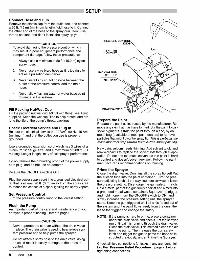
Connect Hose and GunRemove the plastic cap from the outlet tee, and connecta 50 ft. (15 m) (minimum length) fluid hose to it. Connectthe other end of the hose to the spray gun. Don’t usethread sealant, and don’t install the spray tip yet!
To avoid damaging the pressure control, whichmay result in poor equipment performance andcomponent damage, follow these precautions:
1. Always use a minimum of 50 ft. (15.2 m) nylonspray hose.
2. Never use a wire braid hose as it is too rigid toact as a pulsation dampener.
3. Never install any shutof f device between theoutlet of the pressure control and the mainhose.
4. Never allow flushing water or water base paintto freeze in the system.
CAUTION
Fill Packing Nut/Wet CupFill the packing nut/wet cup 1/3 full with throat seal liquid,supplied. Keep the wet cup filled to help protect and pro-long the life of the pump’s throat packings.
Check Electrical Service and Plug InBe sure the electrical service is 120 VAC, 60 Hz, 15 Amp(minimum) and that the outlet you use is properlygrounded.
Use a grounded extension cord which has 3 wires of aminimum 12 gauge size, and a maximum of 200 ft. (61m) long. Longer lengths may affect sprayer performance.
Do not remove the grounding prong of the power supplycord plug, and do not use an adapter.
Be sure the ON/OFF switch is OFF.
Plug the power supply cord into a grounded electrical out-let that is at least 20 ft. (6 m) away from the spray areato reduce the chance of a spark igniting the spray vapors.
Set Pressure ControlTurn the pressure control knob to the lowest setting.
Flush the PumpAn important part of the care and maintenance of yoursprayer is proper flushing. Refer to page 9.
CAUTIONNever operate the sprayer without the drain valvein place. The drain valve is used to help relieve sys-tem pressure and to help prime the sprayer.
Do not attach a spray hose to the drain valve; doingso could result in costly damage to the pressurecontrol.
PRESSURE CONTROLKNOB
1/4 NPT(M)OUTLET
DRAIN VALVE
PACKING NUT/WET CUP
FILL HERE
0804
Prepare the PaintPrepare the paint as instructed by the manufacturer. Re-move any skin that may have formed. Stir the paint to dis-solve pigments. Strain the paint through a fine, nylon–mesh bag (available at most paint dealers) to removeparticles that might clog the spray tip. This is probably themost important step toward trouble–free spray painting.
New paint seldom needs thinning. Add solvent to old andremixed paints to replace the solvent lost through evapo-ration. Do not add too much solvent as thin paint is hardto control and doesn’t cover very well. Follow the paintmanufacturer’s recommendations on thinning.
Prime the SprayerClose the drain valve. Don’t install the spray tip yet! Putthe suction tube into the paint container . Turn the pres-sure adjusting knob all the way counterclockwise to lowerthe pressure setting. Disengage the gun safety latch.Hold a metal part of the gun firmly against and aimed intoa grounded metal waste container. Squeeze the triggerand hold it open, turn the ON/OFF switch to ON, andslowly increase the pressure setting until the sprayerstarts. Keep the gun triggered until all air is forced out ofthe system and the paint flows freely from the gun. Re-lease the trigger and engage the safety.
NOTE: If the pump is hard to prime, place a containerunder the drain valve and open it. Let the sprayerrun until paint is running through the drain valve.Close the drain valve. This method bleeds the airfrom the pump. Then release the gun safetylatch and trigger the gun to prime the hose as in-structed previously, under Prime the Sprayer.
Check all fluid connections for leaks. If any are found, fol-low the Pressure Relief Procedure , page 2, beforetightening connections.

��������
FLUSHING GUIDELINES
When To Flush
1. Before using your new sprayer. Your new sprayerwas factory tested with motor oil and the oil was left.in it to protect the pump parts.
Before using water–based paint, flush out the oil withmineral spirits, followed by soapy water , and thenwith clean water.
Before using oil–based paint, flush out the oil withmineral spirits only.
2. Whenever you change the color of your paintsupply. Flush with a compatible solvent such asmineral spirits or water.
3. Whenever you change from water–based to oil–based paint. Flush with soapy water, then with min-eral spirits.
4. Whenever you change from oil–based to water–based paint. Flush with mineral spirits, followed bysoapy water, then with clean water.
5. Before you store your sprayer. When using water–based paint: Flush with water , then mineral spirits.Leave the pump, hose and gun filled with mineralspirits. Shut of f and unplug the sprayer , open thedrain valve to relieve pressure and leave it open.
When using oil–based paint: Flush with mineral spir-its. Leave the pump, hose and gun filled with mineralspirits. Shut of f and unplug the sprayer , open thedrain valve to relieve pressure and leave it open.
6. Before you use your sprayer after storage.
Before using water–based paint: Flush out mineralspirits with soapy water and then with clean water.
Before using oil–based paint: Flush out mineral spir-its with the fluid to be sprayed.
How To Flush
1. Follow the Pressure Relief Procedure on page 2.
2. Pour 1/2 gallon (2 liters) of compatible solvent (seeWhen to Flush into a bare metal pail. Put the pumpsuction tube in the pail.
3. Be sure the pressure control knob is set at minimum,and the drain valve is closed.
4. Remove the spray tip from the gun.
5. Disengage the gun safety latch.
WARNING
To reduce the risk of static sparking and splashing,always remove the spray tip from the gun, and holda metal part of the gun firmly to the side of agrounded metal pail when flushing.
6. Point the spray gun into a grounded metal pail, andwith a metal part of the gun firmly touching the metalcontainer, squeeze the gun trigger. This procedurehelps reduce the risk of static sparking andsplashing. With the gun triggered, turn the ON/OFFswitch to ON and slowly turn the pressure adjustingknob clockwise just until the sprayer starts. Keepthe gun triggered until clean solvent comes from thenozzle.
7. Release the trigger. Open the drain valve to flush it.
8. Release the trigger and engage the gun safety latch.Close the drain valve.
9. Check all fluid connections for leaks. If there are anyleaks, follow the Pressure Relief Procedure , onpage 2. Tighten the connections, start the sprayer ,and check to be sure the leaking has stopped.
10. Remove the suction tube from the pail. Disengagethe gun safety latch and trigger the gun into agrounded metal pail to force solvent from the hose.Do not let the pump run dry for more than 30 sec-onds to avoid damaging the pump packings!
11. Engage the gun safety latch, turn the sprayer to OFF,and unplug the sprayer. Open the drain valve.
12. If you flushed with mineral spirits and are going to usea water–based paint, flush again with soapy water ,and then with clean water. Then follow the PressureRelief Procedure on page 2.
MAINTAIN FIRMMETAL-TO-METALCONTACT BETWEENGUN AND GROUNDEDMETAL CONTAINER 0667
�� �������
ADJUST THE SPRAY PATTERN
Increase the pressure adjusting knob setting just untilspray from the gun is completely atomized. Use the low-est pressure necessary to get the desired results, whichhelps prolong the life of your sprayer and minimizes paintlost by overspray.
Test the spray pattern on a piece of light colored paper.The tip position determines the direction of the patternwidth. Before adjusting the pattern always follow thePressure Relief Procedure Warning on page 11.
Cleaning and Clearing the Spray Tip
To reduce the risk of injection injury, DO NOT holdyour hand, body, or a rag in front of the spray tipwhen cleaning or checking a clogged tip. Alwayspoint the gun toward the ground or into a waste con-tainer when checking to see if the tip is clear.
DO NOT try to “blow back” paint; this is NOT airspray equipment.
If the spray tip clogs while spraying, engage the gunsafety latch immediately. DO NOT wipe build up offthe gun or tip until pressure is fully relieved. See thePressure Relief Procedure Warning on page 11.
WARNING
Clean out the front of the spray tip frequently during dailyoperation. First, follow the Pressure Relief ProcedureWarning page 11. Then use a solvent soaked brush toclean the spray tip and to keep build up from drying andclogging the spray tip.
APPLICATION METHODS
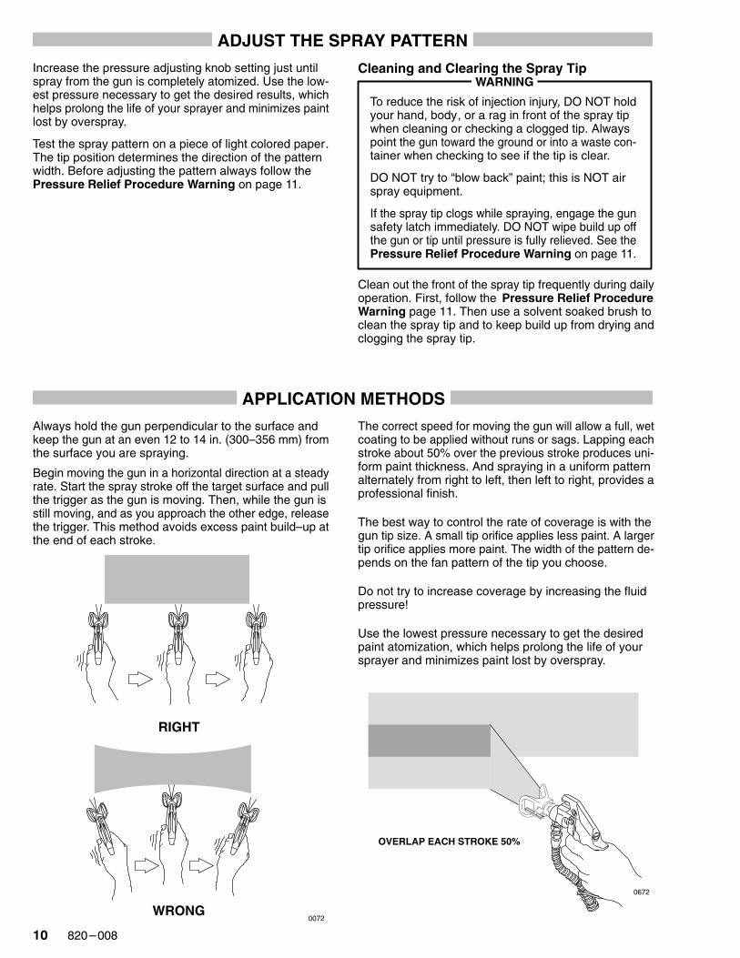
Always hold the gun perpendicular to the surface andkeep the gun at an even 12 to 14 in. (300–356 mm) fromthe surface you are spraying.
Begin moving the gun in a horizontal direction at a steadyrate. Start the spray stroke off the target surface and pullthe trigger as the gun is moving. Then, while the gun isstill moving, and as you approach the other edge, releasethe trigger. This method avoids excess paint build–up atthe end of each stroke.
RIGHT
WRONG0072
The correct speed for moving the gun will allow a full, wetcoating to be applied without runs or sags. Lapping eachstroke about 50% over the previous stroke produces uni-form paint thickness. And spraying in a uniform patternalternately from right to left, then left to right, provides aprofessional finish.
The best way to control the rate of coverage is with thegun tip size. A small tip orifice applies less paint. A largertip orifice applies more paint. The width of the pattern de-pends on the fan pattern of the tip you choose.
Do not try to increase coverage by increasing the fluidpressure!
Use the lowest pressure necessary to get the desiredpaint atomization, which helps prolong the life of yoursprayer and minimizes paint lost by overspray.
OVERLAP EACH STROKE 50%
0672
���������
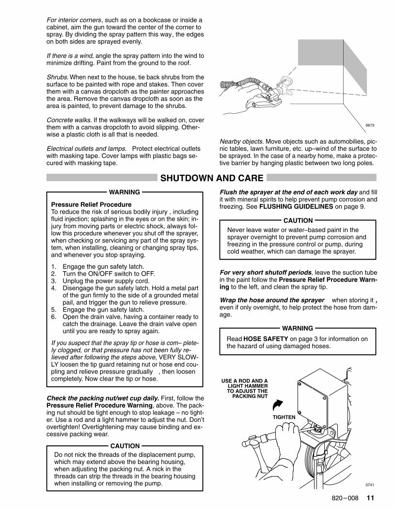
For interior corners, such as on a bookcase or inside acabinet, aim the gun toward the center of the corner tospray. By dividing the spray pattern this way, the edgeson both sides are sprayed evenly.
If there is a wind, angle the spray pattern into the wind tominimize drifting. Paint from the ground to the roof.
Shrubs. When next to the house, tie back shrubs from thesurface to be painted with rope and stakes. Then coverthem with a canvas dropcloth as the painter approachesthe area. Remove the canvas dropcloth as soon as thearea is painted, to prevent damage to the shrubs.
Concrete walks. If the walkways will be walked on, coverthem with a canvas dropcloth to avoid slipping. Other-wise a plastic cloth is all that is needed.
Electrical outlets and lamps. Protect electrical outletswith masking tape. Cover lamps with plastic bags se-cured with masking tape.
0673
Nearby objects. Move objects such as automobilies, pic-nic tables, lawn furniture, etc. up–wind of the surface tobe sprayed. In the case of a nearby home, make a protec-tive barrier by hanging plastic between two long poles.
SHUTDOWN AND CARE
Pressure Relief ProcedureTo reduce the risk of serious bodily injury , includingfluid injection; splashing in the eyes or on the skin; in-jury from moving parts or electric shock, always fol-low this procedure whenever you shut off the sprayer,when checking or servicing any part of the spray sys-tem, when installing, cleaning or changing spray tips,and whenever you stop spraying.
1. Engage the gun safety latch.2. Turn the ON/OFF switch to OFF.3. Unplug the power supply cord.4. Disengage the gun safety latch. Hold a metal part
of the gun firmly to the side of a grounded metalpail, and trigger the gun to relieve pressure.
5. Engage the gun safety latch.6. Open the drain valve, having a container ready to
catch the drainage. Leave the drain valve openuntil you are ready to spray again.
If you suspect that the spray tip or hose is com– plete-ly clogged, or that pressure has not been fully re-lieved after following the steps above, VERY SLOW-LY loosen the tip guard retaining nut or hose end cou-pling and relieve pressure gradually , then loosencompletely. Now clear the tip or hose.
WARNING
Check the packing nut/wet cup daily. First, follow thePressure Relief Procedure Warning, above. The pack-ing nut should be tight enough to stop leakage – no tight-er. Use a rod and a light hammer to adjust the nut. Don’tovertighten! Overtightening may cause binding and ex-cessive packing wear.
CAUTIONDo not nick the threads of the displacement pump,which may extend above the bearing housing,when adjusting the packing nut. A nick in thethreads can strip the threads in the bearing housingwhen installing or removing the pump.
Flush the sprayer at the end of each work day and fillit with mineral spirits to help prevent pump corrosion andfreezing. See FLUSHING GUIDELINES on page 9.
CAUTIONNever leave water or water–based paint in thesprayer overnight to prevent pump corrosion andfreezing in the pressure control or pump, duringcold weather, which can damage the sprayer.
For very short shutoff periods, leave the suction tubein the paint follow the Pressure Relief Procedure Warn-ing to the left, and clean the spray tip.
Wrap the hose around the sprayer when storing it ,even if only overnight, to help protect the hose from dam-age.
WARNING
Read HOSE SAFETY on page 3 for information onthe hazard of using damaged hoses.
USE A ROD AND ALIGHT HAMMERTO ADJUST THE
PACKING NUT
TIGHTEN
0741
�� �������
TROUBLESHOOTING GUIDE
This guide will help you identify the causes and solutions to sprayer problems. If you cannot identify and resolve theproblem, or if “Return for repair” is indicated, contact your nearest authorized service agency for instructions on whereand how to return the sprayer for repair.
Pressure Relief ProcedureTo reduce the risk of serious bodily injury , includingfluid injection; splashing in the eyes or on the skin; inju-ry from moving parts or electric shock, always followthis procedure whenever you shut of f the sprayer ,when checking or servicing any part of the spray sys-tem, when installing, cleaning or changing spray tips,and whenever you stop spraying.
1. Engage the gun safety latch.
2. Turn the ON/OFF switch to OFF.
3. Unplug the power supply cord.
4. Disengage the gun safety latch. Hold a metal partof the gun firmly to the side of a grounded metalpail, and trigger the gun to relieve pressure.
5. Engage the gun safety latch.
6. Open the drain valve, having a container ready tocatch the drainage. Leave the drain valve open un-til you are ready to spray again.
If you suspect that the spray tip or hose is completelyclogged, or that pressure has not been fully relieved af-ter following the steps above, VERY SLOWLY loosenthe tip guard retaining nut or hose end coupling and re-lieve pressure gradually, then loosen completely. Nowclear the tip or hose obstruction.
WARNING
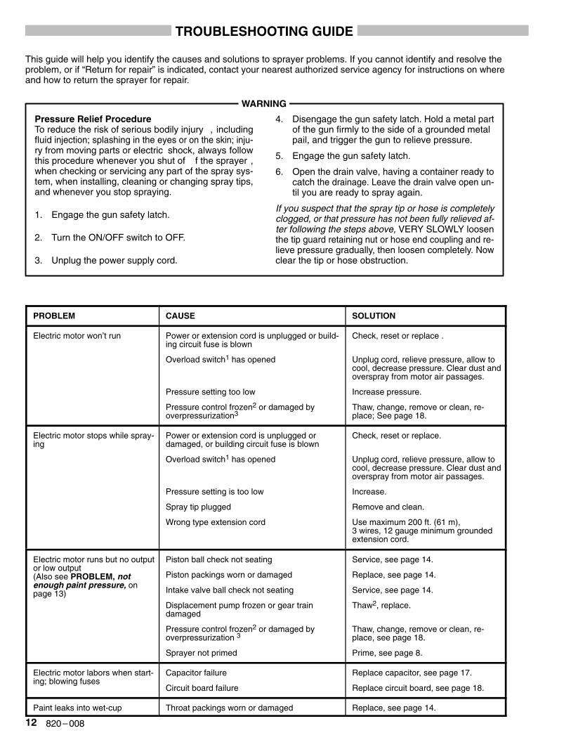
PROBLEM CAUSE SOLUTION
Electric motor won’t run Power or extension cord is unplugged or build-ing circuit fuse is blown
Overload switch1 has opened
Pressure setting too low
Pressure control frozen2 or damaged byoverpressurization3
Check, reset or replace .
Unplug cord, relieve pressure, allow tocool, decrease pressure. Clear dust andoverspray from motor air passages.
Increase pressure.
Thaw, change, remove or clean, re-place; See page 18.
Electric motor stops while spray-ing
Power or extension cord is unplugged or damaged, or building circuit fuse is blown
Overload switch1 has opened
Pressure setting is too low
Spray tip plugged
Wrong type extension cord
Check, reset or replace.
Unplug cord, relieve pressure, allow tocool, decrease pressure. Clear dust andoverspray from motor air passages.
Increase.
Remove and clean.
Use maximum 200 ft. (61 m), 3 wires, 12 gauge minimum groundedextension cord.
Electric motor runs but no outputor low output(Also see PROBLEM, notenough paint pressure, onpage 13)
Piston ball check not seating
Piston packings worn or damaged
Intake valve ball check not seating
Displacement pump frozen or gear train damaged
Pressure control frozen2 or damaged by overpressurization 3
Sprayer not primed
Service, see page 14.
Replace, see page 14.
Service, see page 14.
Thaw2, replace.
Thaw, change, remove or clean, re-place, see page 18.
Prime, see page 8.
Electric motor labors when start-ing; blowing fuses
Capacitor failure
Circuit board failure
Replace capacitor, see page 17.
Replace circuit board, see page 18.
Paint leaks into wet-cup Throat packings worn or damaged Replace, see page 14.
���������
TROUBLESHOOTING GUIDE
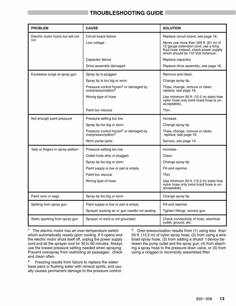
PROBLEM CAUSE SOLUTION
Electric motor hums but will notrun
Circuit board failure
Low voltage
Capacitor failure
Drive assembly damaged
Replace circuit board, see page 18.
Never use more than 200 ft. (61 m) of12 gauge extension cord; use a longfluid hose instead; check power supplywhich should be 110 Volt minimum.
Replace capacitor.
Replace drive assembly; see page 16.
Excessive surge at spray gun Spray tip is plugged
Spray tip is too big or worn
Pressure control frozen2 or damaged byoverpressurization3
Wrong type of hose
Paint too viscous
Remove and clean.
Change spray tip.
Thaw, change, remove or clean, replace; see page 18.
Use minimum 50 ft. (15.2 m) static-freenylon hose only (wire braid hose is un-acceptable).
Thin.
Not enough paint pressure Pressure setting too low
Spray tip too big or worn
Pressure control frozen2 or damaged byoverpressurization3
Worn pump parts
Increase.
Change spray tip.
Thaw, change, remove or clean, replace; see page 18.
Service, see page 14.
Tails or fingers in spray pattern Pressure setting too low
Outlet hose dirty or plugged
Spray tip too big or worn
Paint supply is low or pail is empty
Paint too viscous
Wrong type of hose
Increase.
Clean.
Change spray tip.
Fill and reprime.
Thin.
Use minimum 50 ft. (15.2 m) static-freenylon hose only (wire braid hose is un-acceptable).
Paint runs or sags Spray tip too big or worn Change spray tip.
Spitting from spray gun Paint supply is low or pail is empty
Sprayer sucking air or gun needle not seating
Fill and reprime.
Tighten fittings, service gun.
Static sparking from spray gun Sprayer or work is not grounded Check conductivity of hose, electricaloutlet, ground, etc.
1 The electric motor has an over-temperature switchwhich automatically resets upon cooling. If it opens andthe electric motor shuts itself off, unplug the power supplycord and let the sprayer cool for 30 to 60 minutes. Alwaysuse the lowest pressure setting needed when spraying.Prevent overspray from restricting air passages; checkand clean often.2 Freezing results from failure to replace the water-base paint or flushing water with mineral spirits, and usu-ally causes permanent damage to the pressure control.
3 Over-pressurization results from (1) using less than50 ft. (15.2 m) of nylon spray hose, (2) from using a wirebraid spray hose, (3) from adding a shutof f device be-tween the pump outlet and the spray gun, (4) from attach-ing a spray hose to the pressure drain valve, or (5) fromusing a clogged or incorrectly assembled filter.
�� �������
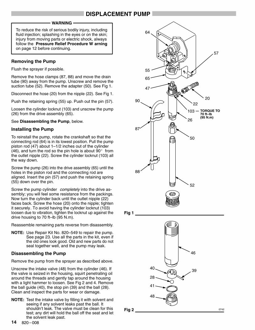
DISPLACEMENT PUMPWARNING
To reduce the risk of serious bodily injury, includingfluid injection; splashing in the eyes or on the skin;injury from moving parts or electric shock, alwaysfollow the Pressure Relief Procedure W arningon page 12 before continuing.
Removing the Pump
Flush the sprayer if possible.
Remove the hose clamps (87, 88) and move the draintube (90) away from the pump. Unscrew and remove thesuction tube (52). Remove the adapter (50). See Fig 1.
Disconnect the hose (20) from the nipple (22). See Fig 1.
Push the retaining spring (55) up. Push out the pin (57).
Loosen the cylinder locknut (103) and unscrew the pump(26) from the drive assembly (65).
See Disassembling the Pump, below.
Installing the Pump
To reinstall the pump, rotate the crankshaft so that theconnecting rod (64) is in its lowest position. Pull the pumppiston rod (47) about 1–1/2 inches out of the cylinder(46), and turn the rod so the pin hole is about 90� fromthe outlet nipple (22). Screw the cylinder locknut (103) allthe way down.
Screw the pump (26) into the drive assembly (65) until theholes in the piston rod and the connecting rod arealigned. Insert the pin (57) and push the retaining spring(55) down over the pin.
Screw the pump cylinder completely into the drive as-sembly; you will feel some resistance from the packings.Now turn the cylinder back until the outlet nipple (22)faces back. Screw the hose (20) onto the nipple; tightenit securely. To avoid having the cylinder locknut (103)loosen due to vibration, tighten the locknut up against thedrive housing to 70 ft–lb (95 N.m).
Reassemble remaining parts reverse from disassembly.
NOTE: Use Repair Kit No. 820–549 to repair the pump.See page 23. Use all the parts in the kit, even ifthe old ones look good. Old and new parts do notseal together well, and the pump may leak.
Disassembling the Pump
Remove the pump from the sprayer as described above.
Unscrew the intake valve (48) from the cylinder (46). Ifthe valve is seized in the housing, squirt penetrating oilaround the threads and gently tap around the housingwith a light hammer to loosen. See Fig 2 and 4. Removethe ball guide (40), the stop pin (39) and the ball (28).Clean and inspect the parts for wear or damage.
NOTE: Test the intake valve by filling it with solvent andseeing if any solvent leaks past the ball. Itshouldn’t leak. The valve must be clean for thistest; any dirt will hold the ball off the seat and letthe solvent leak past.
Fig 1
Fig 2
88
87
90
65
55
64
57
2022
26
52
46
28
40
41
48
39
47
50
103
0742
TORQUE TO70 ft–lb(95 N.m)
���������
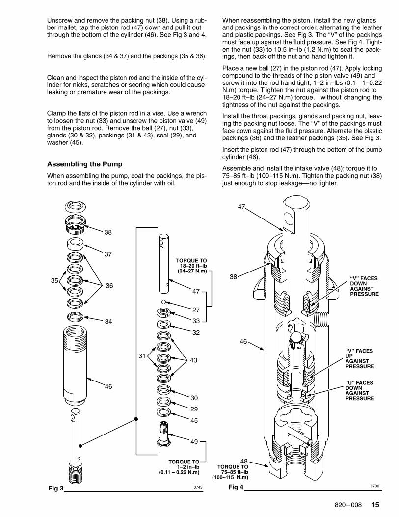
Unscrew and remove the packing nut (38). Using a rub-ber mallet, tap the piston rod (47) down and pull it outthrough the bottom of the cylinder (46). See Fig 3 and 4.
Remove the glands (34 & 37) and the packings (35 & 36).
Clean and inspect the piston rod and the inside of the cyl-inder for nicks, scratches or scoring which could causeleaking or premature wear of the packings.
Clamp the flats of the piston rod in a vise. Use a wrenchto loosen the nut (33) and unscrew the piston valve (49)from the piston rod. Remove the ball (27), nut (33),glands (30 & 32), packings (31 & 43), seal (29), andwasher (45).
Assembling the Pump
When assembling the pump, coat the packings, the pis-ton rod and the inside of the cylinder with oil.
When reassembling the piston, install the new glandsand packings in the correct order, alternating the leatherand plastic packings. See Fig 3. The “V” of the packingsmust face up against the fluid pressure. See Fig 4. Tight-en the nut (33) to 10.5 in–lb (1.2 N.m) to seat the pack-ings, then back off the nut and hand tighten it.
Place a new ball (27) in the piston rod (47). Apply lockingcompound to the threads of the piston valve (49) andscrew it into the rod hand tight, 1–2 in–lbs (0.1 1–0.22N.m) torque. T ighten the nut against the piston rod to18–20 ft–lb (24–27 N.m) torque, without changing thetightness of the nut against the packings.
Install the throat packings, glands and packing nut, leav-ing the packing nut loose. The “V” of the packings mustface down against the fluid pressure. Alternate the plasticpackings (36) and the leather packings (35). See Fig 3.
Insert the piston rod (47) through the bottom of the pumpcylinder (46).
Assemble and install the intake valve (48); torque it to75–85 ft–lb (100–115 N.m). Tighten the packing nut (38)just enough to stop leakage––no tighter.
Fig 3
38
37
3635
34
46
47
27
33
32
4331
30
29
45
49
TORQUE TO1–2 in–lb
(0.11 – 0.22 N.m)
TORQUE TO18–20 ft–lb
(24–27 N.m)
Fig 40743 0700
TORQUE TO75–85 ft–lb
(100–115 N.m)
48
46
47
38 “V” FACESDOWNAGAINSTPRESSURE
“V” FACESUPAGAINSTPRESSURE
“U” FACESDOWNAGAINSTPRESSURE
�� �������
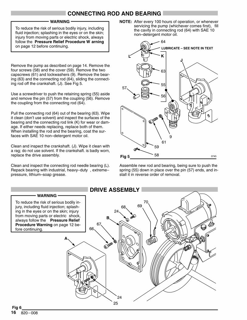
CONNECTING ROD AND BEARINGWARNING
To reduce the risk of serious bodily injury, includingfluid injection; splashing in the eyes or on the skin;injury from moving parts or electric shock, alwaysfollow the Pressure Relief Procedure W arningon page 12 before continuing.
Remove the pump as described on page 14. Remove thefour screws (58) and the cover (59). Remove the twocapscrews (61) and lockwashers (9). Remove the bear-ing (63) and the connecting rod (64), sliding the connect-ing rod off the crankshaft. (J). See Fig 5.
Use a screwdriver to push the retaining spring (55) asideand remove the pin (57) from the coupling (56). Removethe coupling from the connecting rod (64).
Pull the connecting rod (64) out of the bearing (63). Wipeit clean (don’t use solvent) and inspect the surfaces of thebearing and the connecting rod link (K) for wear or dam-age. If either needs replacing, replace both of them.When installing the rod and the bearing, coat the sur-faces with SAE 10 non–detergent motor oil.
Clean and inspect the crankshaft. (J). Wipe it clean witha rag; do not use solvent. If the crankshaft. is badly worn,replace the drive assembly.
Clean and inspect the connecting rod needle bearing (L).Repack bearing with industrial, heavy–duty , extreme–pressure, lithium–soap grease.
NOTE: After every 100 hours of operation, or wheneverservicing the pump (whichever comes first), fillthe cavity in connecting rod (64) with SAE 10non–detergent motor oil.
Fig 5
64
63
55
56
57
961
59
58
JKL
LUBRICATE – SEE NOTE IN TEXT
0745
Assemble new rod and bearing, being sure to push thespring (55) down in place over the pin (57) ends, and in-stall it in reverse order of removal.
DRIVE ASSEMBLYWARNING
To reduce the risk of serious bodily in-jury, including fluid injection; splash-ing in the eyes or on the skin; injuryfrom moving parts or electric shock,always follow the Pressure ReliefProcedure Warning on page 12 be-fore continuing.
���� �
��
��
��
���
��
��
��
�
�
���������
Remove the pump, connecting rod and bearing as de-scribed on pages 14 and 16.
Remove the capscrews (25 & 68), lockwashers (24), anddrive housing (A). Remove the screws (66), lockwashers(67), and motor housing (B). See Fig 6.
Clean and inspect the gear (69) for wear or damage. Re-place it if necessary. To remove the gear, drive out the pin(70), and pull it of f the motor shaft. Apply molybdenumdisulfide spray lubricant to the new gear, allow to dry, thenapply industrial, heavy–duty extreme–pressure, lithium–soap grease.
Install new drive assembly in reverse order of removal.
CAPACITOR
WARNING
To reduce the risk of serious bodily injury, includingfluid injection; splashing in the eyes or on the skin;injury from moving parts or electric shock, alwaysfollow the Pressure Relief Procedure W arningon page 12 before continuing.
Unplug the sprayer. Remove the cover of the capacitor(5). See Fig 7. Remove the flag connectors from the oldcapacitor. Connect the flag connectors of the new capac-itor and replace the cover.
NOTE: The replacement capacitor includes a new resis-tor already installed.
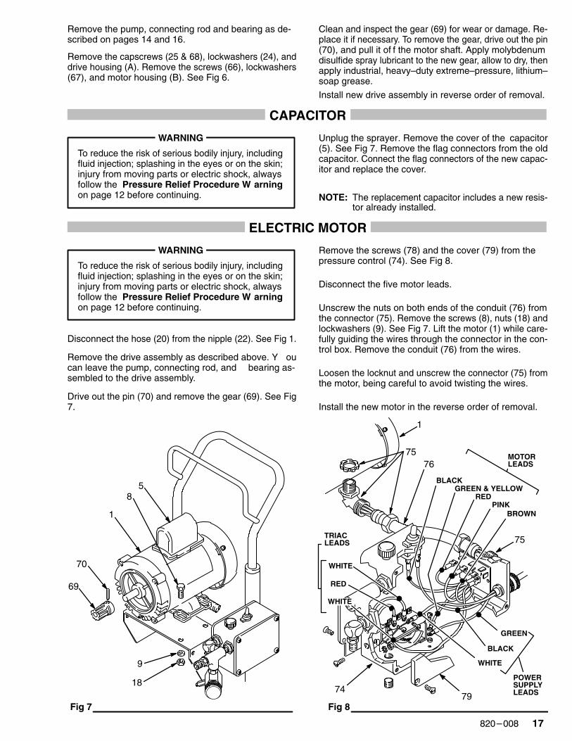
ELECTRIC MOTOR
WARNING
To reduce the risk of serious bodily injury, includingfluid injection; splashing in the eyes or on the skin;injury from moving parts or electric shock, alwaysfollow the Pressure Relief Procedure W arningon page 12 before continuing.
Disconnect the hose (20) from the nipple (22). See Fig 1.
Remove the drive assembly as described above. Y oucan leave the pump, connecting rod, and bearing as-sembled to the drive assembly.
Drive out the pin (70) and remove the gear (69). See Fig7.
Remove the screws (78) and the cover (79) from thepressure control (74). See Fig 8.
Disconnect the five motor leads.
Unscrew the nuts on both ends of the conduit (76) fromthe connector (75). Remove the screws (8), nuts (18) andlockwashers (9). See Fig 7. Lift the motor (1) while care-fully guiding the wires through the connector in the con-trol box. Remove the conduit (76) from the wires.
Loosen the locknut and unscrew the connector (75) fromthe motor, being careful to avoid twisting the wires.
Install the new motor in the reverse order of removal.
Fig 7 Fig 8
9
18
5
1
70
69
8 RED
BLACK
BROWN
WHITE
GREEN
76
75
75
79
PINK
BLACK
POWERSUPPLYLEADS
GREEN & YELLOW
MOTORLEADS
RED
WHITE
TRIACLEADS
1
74
WHITE
�� �������
PRESSURE CONTROL AND CIRCUIT BOARD
WARNING
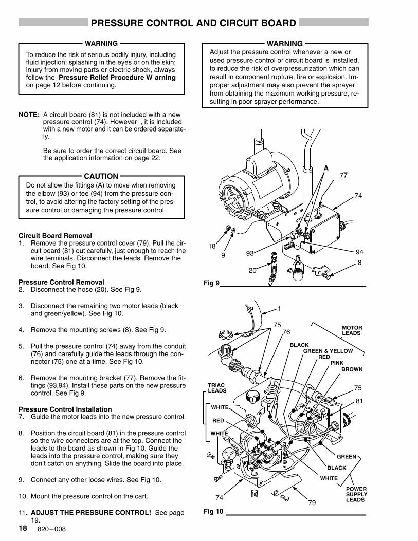
To reduce the risk of serious bodily injury, includingfluid injection; splashing in the eyes or on the skin;injury from moving parts or electric shock, alwaysfollow the Pressure Relief Procedure W arningon page 12 before continuing.
NOTE: A circuit board (81) is not included with a newpressure control (74). However , it is includedwith a new motor and it can be ordered separate-ly.
Be sure to order the correct circuit board. Seethe application information on page 22.
Do not allow the fittings (A) to move when removingthe elbow (93) or tee (94) from the pressure con-trol, to avoid altering the factory setting of the pres-sure control or damaging the pressure control.
CAUTION
Circuit Board Removal1. Remove the pressure control cover (79). Pull the cir-
cuit board (81) out carefully, just enough to reach thewire terminals. Disconnect the leads. Remove theboard. See Fig 10.
Pressure Control Removal2. Disconnect the hose (20). See Fig 9.
3. Disconnect the remaining two motor leads (blackand green/yellow). See Fig 10.
4. Remove the mounting screws (8). See Fig 9.
5. Pull the pressure control (74) away from the conduit(76) and carefully guide the leads through the con-nector (75) one at a time. See Fig 10.
6. Remove the mounting bracket (77). Remove the fit-tings (93,94). Install these parts on the new pressurecontrol. See Fig 9.
Pressure Control Installation7. Guide the motor leads into the new pressure control.
8. Position the circuit board (81) in the pressure controlso the wire connectors are at the top. Connect theleads to the board as shown in Fig 10. Guide theleads into the pressure control, making sure theydon’t catch on anything. Slide the board into place.
9. Connect any other loose wires. See Fig 10.
10. Mount the pressure control on the cart.
11. ADJUST THE PRESSURE CONTROL! See page19.
Adjust the pressure control whenever a new orused pressure control or circuit board is installed,to reduce the risk of overpressurization which canresult in component rupture, fire or explosion. Im-proper adjustment may also prevent the sprayerfrom obtaining the maximum working pressure, re-sulting in poor sprayer performance.
WARNING
Fig 9
Fig 10
93
20
74
189
8
94
RED
BLACK
BROWN
WHITE
GREEN
76
75
75
79
PINK
BLACK
POWERSUPPLYLEADS
GREEN & YELLOW
MOTORLEADS
WHITE
RED
WHITE
TRIACLEADS
1
74
81
A77
���������
PRESSURE CONTROL CALIBRATION
USE EXTREME CAUTION WHEN PERFORMING THIS CALIBRATION PROCEDURE to reduce the risk of aninjection injury or other serious bodily injury which can result from component rupture, electric shock, fire, explo-sion, or moving parts.
This procedure sets the sprayer to 2750 psi (190 bar)MAXIMUM WORKING PRESSURE.
This procedure must be performed whenever micros-witch or pressure control assembly is removed and re-installed or replaced to be sure the sprayer is properlycalibrated.
Improper calibration can cause the sprayer to over-pressurize and result in component rupture, fire or ex-plosion. It may also prevent the sprayer from obtainingthe maximum working pressure which would result inpoor sprayer performance.
NEVER try to increase the fluid outlet pressure by per-forming these calibrations in any other way . Normaloperation of the sprayer at higher pressures could re-sult in component rupture, fire or explosion. To performthis adjustment, however, the sprayer pressure mustbe temporarily increased above the normal workingpressure.
Use a new 50 foot (15.2 m) spray hose rated for 3000psi (210 bar) MAXIMUM WORKING PRESSUREwhen performing this procedure. A used, under–ratedhose could develop a high pressure leak or rupture.
WARNING
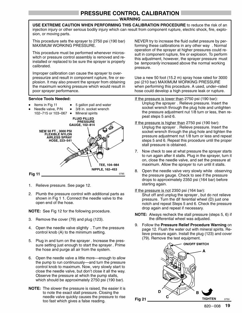
Service Tools Needed:
� Items in Fig 11 � 5 gallon pail and water� Needle valve, P/N � 3/8 in. socket wrench
102–715 or 103–067 � Mineral spirits
Fig 11 0785
TEE, 104–984
FLUID FILLED PRESSURE
GAUGE, 102–814
NEW 50 FT. , 3000 PSIFLEXIBLE NYLON
AIRLESS SPRAYHOSE, 223–541
NIPPLE, 162–453
1. Relieve pressure. See page 12.
2. Plumb the pressure control with additional parts asshown in Fig 1 1. Connect the needle valve to theopen end of the hose.
NOTE: See Fig 12 for the following procedure.
3. Remove the cover (79) and plug (123).
4. Open the needle valve slightly . Turn the pressurecontrol knob (A) to the minimum setting.
5. Plug in and turn on the sprayer . Increase the pres-sure setting just enough to start the sprayer . Primethe hose and purge all air from the system.
6. Open the needle valve a little more––enough to allowthe pump to run continuously––and turn the pressurecontrol knob to maximum. Now, very slowly start toclose the needle valve, but don’t close it all the way.Observe the pressure at which the pump stalls,which should be approximately 2750 psi (190 bar).
NOTE: The slower the pressure is raised, the easier it isto note the exact stall pressure. Closing theneedle valve quickly causes the pressure to risetoo fast which gives a false reading.
If the pressure is lower than 2750 psi (190 bar):Unplug the sprayer . Relieve pressure. Insert thesocket wrench through the plug hole and untightenthe pressure adjustment nut 1/8 turn or less, then re-peat steps 5 and 6.
If the pressure is higher than 2750 psi (190 bar):Unplug the sprayer . Relieve pressure. Insert thesocket wrench through the plug hole and tighten thepressure adjustment nut 1/8 turn or less and repeatsteps 5 and 6. Repeat this procedure until the properstall pressure is obtained.
7. Now check to see at what pressure the sprayer startsto run again after it stalls. Plug in the sprayer, turn iton, close the needle valve, and set the pressure atmaximum. Allow the sprayer to run until it stalls.
8. Open the needle valve very slowly while observingthe pressure gauge. Check to see if the pressuredrops to approximately 2350 psi (164 bar) beforestarting again.
If the pressure is not 2350 psi (164 bar):Shut off and unplug the sprayer , but do not relievepressure. Turn the dif ferential wheel (D) just onenotch and repeat Steps 5 and 6. Check the pressuredrop again and repeat if necessary.
NOTE: Always recheck the stall pressure (steps 5, 6) ifthe differential wheel was adjusted.
9. Follow the Pressure Relief Procedure Warning onpage 12. Flush the water out with mineral spirits. Re-lieve pressure again. Install the plug (123) and cover(79). Remove the test equipment.
Fig 21
ON/OFF SWITCH
A
BD
TIGHTENC0750
�� �������
PARTS LIST
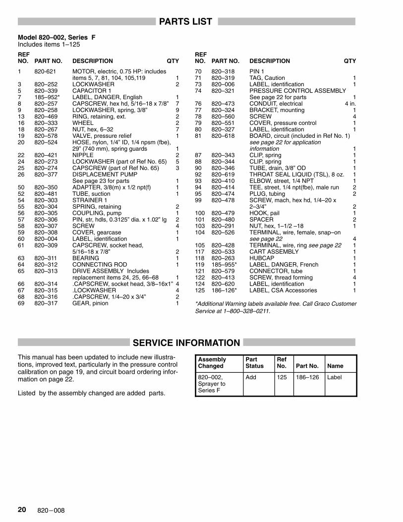
Model 820–002, Series FIncludes items 1–125
REF NO. PART NO. DESCRIPTION QTY
REF NO. PART NO. DESCRIPTION QTY
1 820-621 MOTOR, electric, 0.75 HP: includesitems 5, 7, 81, 104, 105,119 1
3 820–252 LOCKWASHER 25 820–339 CAPACITOR 17 185–952* LABEL, DANGER, English 18 820–257 CAPSCREW, hex hd, 5/16–18 x 7/8” 79 820–258 LOCKWASHER, spring, 3/8” 913 820–469 RING, retaining, ext. 216 820–333 WHEEL 218 820–267 NUT, hex, 6–32 719 820–578 VALVE, pressure relief 120 820–524 HOSE, nylon, 1/4” ID, 1/4 npsm (fbe),
29” (740 mm), spring guards 122 820–421 NIPPLE 224 820–273 LOCKWASHER (part of Ref No. 65) 525 820–274 CAPSCREW (part of Ref No. 65) 326 820–377 DISPLACEMENT PUMP
See page 23 for parts 150 820–350 ADAPTER, 3/8(m) x 1/2 npt(f) 152 820–481 TUBE, suction 154 820–303 STRAINER 155 820–304 SPRING, retaining 256 820–305 COUPLING, pump 157 820–306 PIN, str, hdls, 0.3125” dia. x 1.02” lg 258 820–307 SCREW 459 820–308 COVER, gearcase 160 820–004 LABEL, identification 161 820–309 CAPSCREW, socket head,
5/16–18 x 7/8” 263 820–311 BEARING 164 820–312 CONNECTING ROD 165 820–313 DRIVE ASSEMBLY Includes
replacement items 24, 25, 66–68 166 820–314 .CAPSCREW, socket head, 3/8–16x1” 467 820–315 .LOCKWASHER 468 820–316 .CAPSCREW, 1/4–20 x 3/4” 269 820–317 GEAR, pinion 1
70 820–318 PIN 171 820–319 TAG, Caution 173 820–006 LABEL, identification 174 820–321 PRESSURE CONTROL ASSEMBLY
See page 22 for parts 176 820–473 CONDUIT, electrical 4 in.77 820–324 BRACKET, mounting 178 820–560 SCREW 479 820–551 COVER, pressure control 180 820–327 LABEL, identification 181 820–618 BOARD, circuit (included in Ref No. 1)
see page 22 for application information 1
87 820–343 CLIP, spring 188 820–344 CLIP, spring 190 820–346 TUBE, drain, 3/8” OD 192 820–619 THROAT SEAL LIQUID (TSL), 8 oz. 193 820–410 ELBOW, street, 1/4 NPT 194 820–414 TEE, street, 1/4 npt(fbe), male run 295 820–474 PLUG, tubing 299 820–478 SCREW, mach, hex hd, 1/4–20 x
2–3/4” 2100 820–479 HOOK, pail 1101 820–480 SPACER 2103 820–291 NUT, hex, 1–1/2 –18 1104 820–526 TERMINAL, wire, female, snap–on
see page 22 4105 820–428 TERMINAL, wire, ring see page 22 1117 820–533 CART ASSEMBLY 1118 820–263 HUBCAP 1119 185–955* LABEL, DANGER, French 1121 820–579 CONNECTOR, tube 1122 820–413 SCREW, thread forming 4124 820–620 LABEL, identification 1125 186–126* LABEL, CSA Accessories 1
*Additional Warning labels available free. Call Graco CustomerService at 1–800–328–0211.
SERVICE INFORMATIONThis manual has been updated to include new illustra-tions, improved text, particularly in the pressure controlcalibration on page 19, and circuit board ordering infor-mation on page 22.
Listed by the assembly changed are added parts.
AssemblyChanged
Part Status
RefNo. Part No. Name
820–002,Sprayer toSeries F
Add 125 186–126 Label
���������
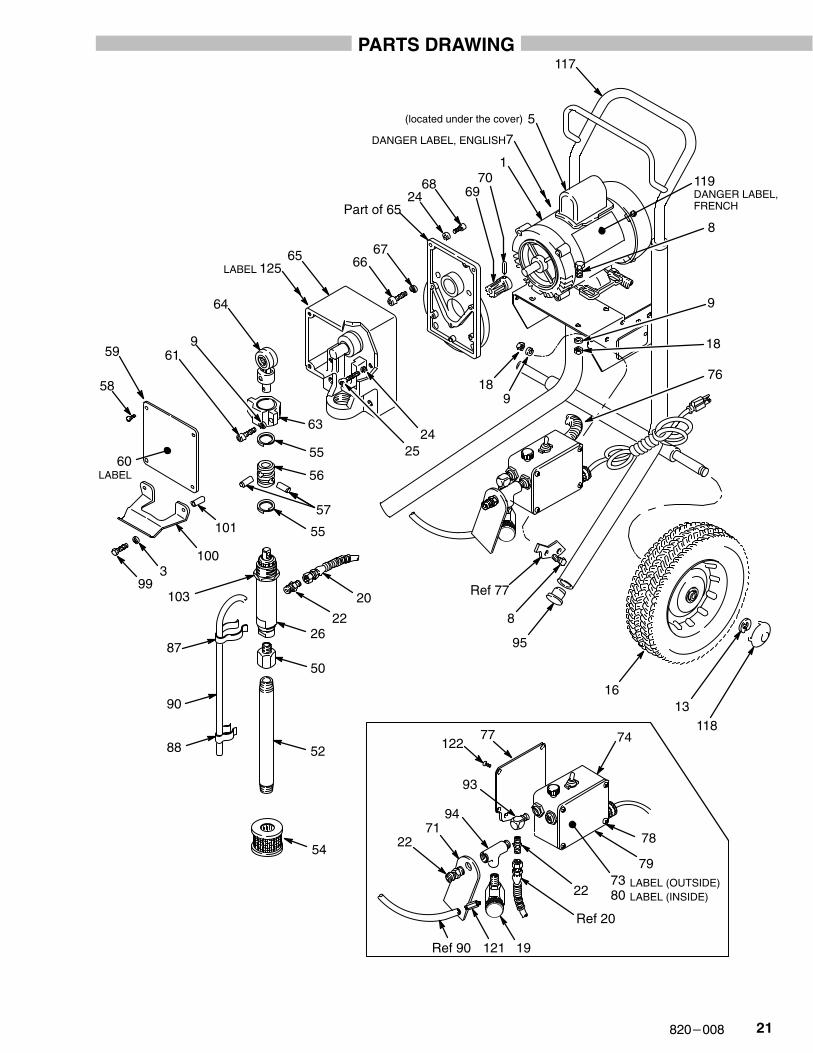
PARTS DRAWING
16
118
117
13
95
918
7069
6824
Part of 65
6766
1
7
5(located under the cover)
119 DANGER LABEL,FRENCH
DANGER LABEL, ENGLISH
Ref 77
8
9
18
8
22
20
26
50
52
54
88
90
87
103
55
55
56
57
63
64
961
65
2524
58
59
993
100
9471
22
Ref 20
121 19Ref 90
78
79
77122
93
22
60LABEL
101
74
LABEL (INSIDE)
7380
LABEL (OUTSIDE)
76
125LABEL
�� �������
PARTS DRAWING AND LIST
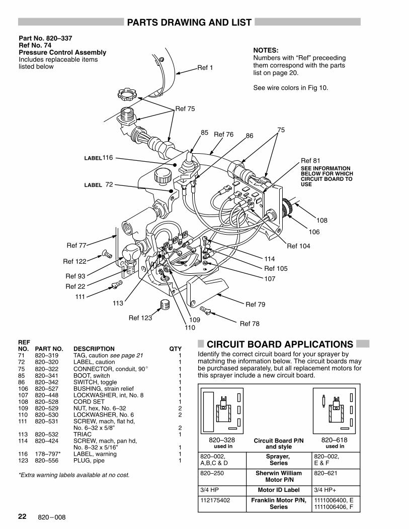
Part No. 820–337Ref No. 74Pressure Control AssemblyIncludes replaceable items listed below
NOTES:Numbers with “Ref” preceedingthem correspond with the partslist on page 20.
See wire colors in Fig 10.
Ref 81116
Ref 77
72
Ref 22
111
SEE INFORMATIONBELOW FOR WHICH CIRCUIT BOARD TOUSE
LABEL
Ref 79
Ref 78
114Ref 105
107
Ref 122
Ref 93
LABEL
109110
Ref 104
75
Ref 75
85 Ref 76 86
Ref 1
Ref 123
113
106
108
REF NO. PART NO. DESCRIPTION QTY71 820–319 TAG, caution see page 21 172 820–320 LABEL, caution 175 820–322 CONNECTOR, conduit, 90� 185 820–341 BOOT, switch 186 820–342 SWITCH, toggle 1106 820–527 BUSHING, strain relief 1107 820–448 LOCKWASHER, int, No. 8 1108 820–528 CORD SET 1109 820–529 NUT, hex, No. 6–32 2110 820–530 LOCKWASHER, No. 6 2111 820–531 SCREW, mach, flat hd,
No. 6–32 x 5/8” 2113 820–532 TRIAC 1114 820–424 SCREW, mach, pan hd,
No. 8–32 x 5/16” 1116 178–797* LABEL, warning 1123 820–556 PLUG, pipe 1
*Extra warning labels available at no cost.
CIRCUIT BOARD APPLICATIONSIdentify the correct circuit board for your sprayer bymatching the information below. The circuit boards maybe purchased separately, but all replacement motors forthis sprayer include a new circuit board.
ÇÇÇ
ÇÇÇ
ÇÇÇ
ÇÇÇ
820–328 820–618Circuit Board P/Nand styleused in used in
820–002,A,B,C & D
Sprayer, Series
820–002,E & F
820–250 Sherwin William Motor P/N
820–621
3/4 HP Motor ID Label 3/4 HP+
112175402 Franklin Motor P/N,Series
1111006400, E1111006406, F
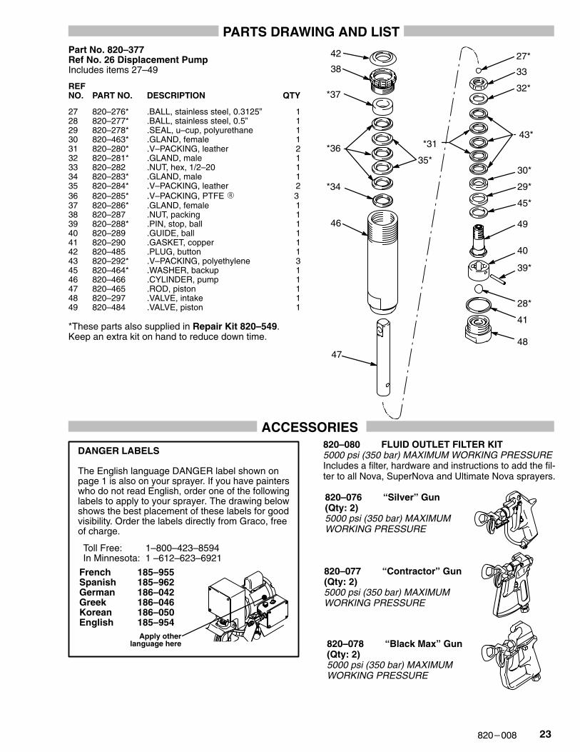
���������
PARTS DRAWING AND LISTPart No. 820–377Ref No. 26 Displacement Pump Includes items 27–49
REF NO. PART NO. DESCRIPTION QTY
27 820–276* .BALL, stainless steel, 0.3125” 128 820–277* .BALL, stainless steel, 0.5” 129 820–278* .SEAL, u–cup, polyurethane 130 820–463* .GLAND, female 131 820–280* .V–PACKING, leather 232 820–281* .GLAND, male 133 820–282 .NUT, hex, 1/2–20 134 820–283* .GLAND, male 135 820–284* .V–PACKING, leather 236 820–285* .V–PACKING, PTFE � 337 820–286* .GLAND, female 138 820–287 .NUT, packing 139 820–288* .PIN, stop, ball 140 820–289 .GUIDE, ball 141 820–290 .GASKET, copper 142 820–485 .PLUG, button 143 820–292* .V–PACKING, polyethylene 345 820–464* .WASHER, backup 146 820–466 .CYLINDER, pump 147 820–465 .ROD, piston 148 820–297 .VALVE, intake 149 820–484 .VALVE, piston 1
*These parts also supplied in Repair Kit 820–549. Keep an extra kit on hand to reduce down time.
43*
47
27*
33
32*
30*
29*
45*
49
40
28*
41
48
*36
42
38
*37
35*
*34
46
*31
39*
ACCESSORIES
French 185–955Spanish 185–962German 186–042Greek 186–046Korean 186–050English 185–954
Apply otherlanguage here
DANGER LABELS
The English language DANGER label shown onpage 1 is also on your sprayer. If you have painterswho do not read English, order one of the followinglabels to apply to your sprayer. The drawing belowshows the best placement of these labels for goodvisibility. Order the labels directly from Graco, freeof charge.
Toll Free: 1–800–423–8594In Minnesota: 1 –612–623–6921
820–080 FLUID OUTLET FILTER KIT5000 psi (350 bar) MAXIMUM WORKING PRESSUREIncludes a filter, hardware and instructions to add the fil-ter to all Nova, SuperNova and Ultimate Nova sprayers.
820–076 “Silver” Gun(Qty: 2)5000 psi (350 bar) MAXIMUM WORKING PRESSURE
820–077 “Contractor” Gun(Qty: 2)5000 psi (350 bar) MAXIMUM WORKING PRESSURE
820–078 “Black Max” Gun(Qty: 2)5000 psi (350 bar) MAXIMUM WORKING PRESSURE
�� �������
TECHNICAL DATA
Maximum Working Pressure 2750 psi (190 bar). . . . . . . . . . . . . . . . . . . . . . . . . . . . . . .
Electric Motor 0.75 HP AC, CSA approved. . . . . . . . . . . . . . . . . . . . . . . . . . . . . . . . . . .
Power Requirements 120 V, 60 Hz, 15 amp or 4500 Watt generator. . . . . . . . . . . . . .
Extension Cord Requirements No. 12 gauge, 3–wire, up to 200 ft (61 m). . . . . . . . .
Maximum Delivery 0.44 GPM (1.7 liter/min). . . . . . . . . . . . . . . . . . . . . . . . . . . . . . . . . . .
Fluid Inlet 3/4 npt(m) with 30� chamfer. . . . . . . . . . . . . . . . . . . . . . . . . . . . . . . . . . . . . . .
Fluid Outlet Size 1/4 npsm(m). . . . . . . . . . . . . . . . . . . . . . . . . . . . . . . . . . . . . . . . . . . . . . .
Spray Hose Requirements Grounded, 50 ft. (15 m) minimum, . . . . . . . . . . . . . . . . . . non-wire braid, spring guards both ends
Wetted parts Stainless Steel, Aluminum, Delrin�, PTFE, �. . . . . . . . . . . . . . . . . . . . . Polyethylene, Polyurethane, Tungsten Carbide, Nylon, Nitralloy
Dimensions Weight: 75 lb (34 kg). . . . . . . . . . . . . . . . . . . . . . . . . . . . . . . . . . . . Height: 41 in. (1041 mm) Length: 20.5 in. (421 mm)Width: 20.5 in. (521 mm)
Delrin��
THE SHERWIN-WILLIAMS WARRANTY AND DISCLAIMERS
The Sherwin-Williams Company warrants this sprayer to be free from defects in material and workmanship on thedate of sale to the original purchaser for use. As purchaser’s sole remedy for breach of this warranty, The Sherwin-Williams Company will, for a period of twelve months from the date of sale, repair or replace any part of the equip-ment proven defective, with the exception of defects in parts of the drive train/gear box on Nova� sprayers, whichwill be repaired or replaced for thirty-six months from the date of sale. This warranty applies only when the equip-ment is installed, operated and maintained in accordance with The Sherwin-Williams’ Company written recommen-dations.
This warranty does not cover, and The Sherwin-Williams Company shall not be liable for, any malfunction, damageor wear caused by faulty installation, misapplication, abrasion, corrosion, inadequate or improper maintenance,negligence, accident, tampering, or substitution of non-original equipment manufacturer component parts. Norshall The Sherwin-Williams Company be liable for malfunction, damage or wear caused by the incompatibility withSherwin-Williams equipment of structures, accessories, equipment or materials not supplied by The Sherwin-Wil-liams Company, or the improper design, manufacture, installation, operation or maintenance of structures, acces-sories, equipment or materials not supplied by The Sherwin-Williams Company.
This warranty is conditioned upon the prepaid return of the equipment claimed to be defective to an authorizedSherwin-Williams sales/service outlet for verification of the claimed defect. If the claimed defect is verified, TheSherwin-Williams Company will repair or replace free of charge any defective parts. The equipment will be returnedto the original purchaser transportation prepaid. If inspection of the equipment does not disclose any defect in mate-rial or workmanship, repairs will be made at a reasonable charge, which charges may include the costs of parts,labor, and transportation.
Disclaimers and Limitations. The terms of this warranty constitute purchaser’s sole and exclusive remedyand are in lieu of any other warranties (express or implied), including warranty of merchantability or warran-ty of fitness for a particular purpose, and of any non-contractual liabilities, including product liabilitiesbased on negligence or strict liability. Every form of liability for direct special or consequential damages orloss is expressly excluded and denied. In no case shall The Sherwin-Williams Company liability exceed theamount of the purchase price.
The SHERWIN–WILLIAMS COMPANY, CLEVELAND, OHIO 44115PRINTED IN U.S.A. 820–008 6–81 Revised 9–91
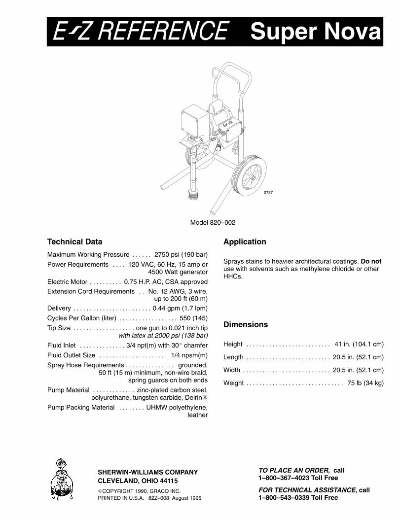
Super Nova
Model 820–002
0737
Technical Data
Maximum Working Pressure 2750 psi (190 bar). . . . . .
Power Requirements 120 VAC, 60 Hz, 15 amp or. . . . 4500 Watt generator
Electric Motor 0.75 H.P. AC, CSA approved. . . . . . . . . .
Extension Cord Requirements No. 12 AWG, 3 wire,. . up to 200 ft (60 m)
Delivery 0.44 gpm (1.7 lpm). . . . . . . . . . . . . . . . . . . . . . . .
Cycles Per Gallon (liter) 550 (145). . . . . . . . . . . . . . . . . .
Tip Size one gun to 0.021 inch tip. . . . . . . . . . . . . . . . . . . with latex at 2000 psi (138 bar)
Fluid Inlet 3/4 npt(m) with 30� chamfer. . . . . . . . . . . . . .
Fluid Outlet Size 1/4 npsm(m). . . . . . . . . . . . . . . . . . . . .
Spray Hose Requirements grounded,. . . . . . . . . . . . . . . 50 ft (15 m) minimum, non-wire braid,
spring guards on both ends
Pump Material zinc-plated carbon steel,. . . . . . . . . . . . . polyurethane, tungsten carbide, Delrin�
Pump Packing Material UHMW polyethylene,. . . . . . . . leather
Application
Sprays stains to heavier architectural coatings. Do notuse with solvents such as methylene chloride or otherHHCs.
Dimensions
Height 41 in. (104.1 cm). . . . . . . . . . . . . . . . . . . . . . . . . .
Length 20.5 in. (52.1 cm). . . . . . . . . . . . . . . . . . . . . . . . . .
Width 20.5 in. (52.1 cm). . . . . . . . . . . . . . . . . . . . . . . . . . .
Weight 75 lb (34 kg). . . . . . . . . . . . . . . . . . . . . . . . . . . . . .
SHERWIN-WILLIAMS COMPANYCLEVELAND, OHIO 44115
�COPYRIGHT 1990, GRACO INC.PRINTED IN U.S.A. 82Z–008 August 1995
TO PLACE AN ORDER, call1–800–367–4023 Toll Free
FOR TECHNICAL ASSISTANCE, call 1–800–543–0339 Toll Free

13c
9
14
10
1
2
3
45
5a
6
5b
7
8
11
�
��
13a
13b
13d
12
13
UNDER THIS COVER
0738
�
82Z–008Rev B
Supplement to instruction manual 820–008.
Super Nova Airless Paint Sprayer
INJECTION HAZARDThis is only a quick reference to the fea-tures and frequently ordered parts of thissprayer. To reduce the risk of serious
injury, including fluid injection, while operating orrepairing this sprayer, follow the warnings and in-structions in manual 820–008.
INSTRUCTIONS
WARNING
Model 820–002, Series F
RefNo. Part No. Description1 820–311 Bearing Assembly2 820–312 Connecting Rod3 820–313 Drive Housing4 820–317 Pinion Gear5 820–621 Motor5a 820–339 Capacitor5b 820–704 Motor Fan6� 185–952 Danger Label7 820–533 Cart8 820–321 Pressure Control8a 820–341 Switch Boot8b 820–342 Toggle Switch9 820–578 Pressure Drain Valve10 820–303 Strainer11 820–481 Suction Tube12 820–346 Drain Tube13 820–377 Displacement Pump13a 820–466 .Cylinder13b 820–465 .Piston Rod13c 820–484 .Piston Valve13d 820–297 .Intake Valve14 820–524 Hose15 Circuit Board, (not shown)
820–328 Series A to D sprayers only 820–618 Series E and F sprayers only
� Extra danger labels are available for free.
Packing Repair Kit 820–549Includes all parts marked with a �