supplementary certificate of approval...2 pattern & variant 6 amended (tables 1 & 2) –...
TRANSCRIPT

NMI S570 Rev 2
Supplementary Certificate of Approval
NMI S570
Issued by the Chief Metrologist under Regulation 60 of the
National Measurement Regulations 1999
This is to certify that an approval for use for trade has been granted in respect of the instruments herein described.
Avery Weigh-Tronix Model ZM303 Digital Indicator
submitted by Avery Weigh-Tronix Foundry Lane Smethwick West Mid land s B66 2LP UK
NOTE: This Certificate relates to the suitability of the pattern of the instrument for use for trade only in respect of its metrological characteristics. This Certificate does not constitute or imply any guarantee of compliance by the manufacturer or any other person with any requirements regarding safety. This approval has been granted with reference to document OIML R 76, Non-automatic weighing instruments, Part 1, Edition 2006. This approval becomes subject to review on 1/12/17, and then every 5 years thereafter.
DOCUMENT HISTORY
Rev Reason/Details Date 0 Pattern & variants 1 to 4 approved – certificate issued 12/11/12 1 Pattern amended – variants 5 to 7 approved – certificate issued 13/07/15 2 Pattern & variant 6 amended (Tables 1 & 2) – certificate issued 18/11/15
Page 1 of 12

NMI S570 Rev 2
CONDITIONS OF APPROVAL General Instruments purporting to comply with this approval shall be marked with approval number ‘NMI S570’ and only by persons authorised by the submittor. Instruments incorporating a component purporting to comply with this approval shall be marked ‘NMI S570’ in addition to the approval number of the instrument, and only by persons authorised by the submittor. It is the submittor’s responsibility to ensure that all instruments marked with this approval number are constructed as described in the documentation lodged with the National Measurement Institute (NMI) and with the relevant Certificate of Approval and Technical Schedule. Failure to comply with this Condition may attract penalties under Section 19B of the National Measurement Act and may result in cancellation or withdrawal of the approval, in accordance with document NMI P 106. The values of the performance criteria (maximum number of scale intervals etc.) applicable to an instrument incorporating the pattern approved herein shall be within the limits specified herein and in any approval documentation for the other components. Auxiliary devices used with this instrument shall comply with the requirements of General Supplementary Certificate No S1/0B.
Signed by a person authorised by the Chief Metrologist to exercise their powers under Regulation 60 of the National Measurement Regulations 1999.
Dr Amanda Rawlinson
Page 2 of 12
NMI S570 Rev 2
TECHNICAL SCHEDULE No S570
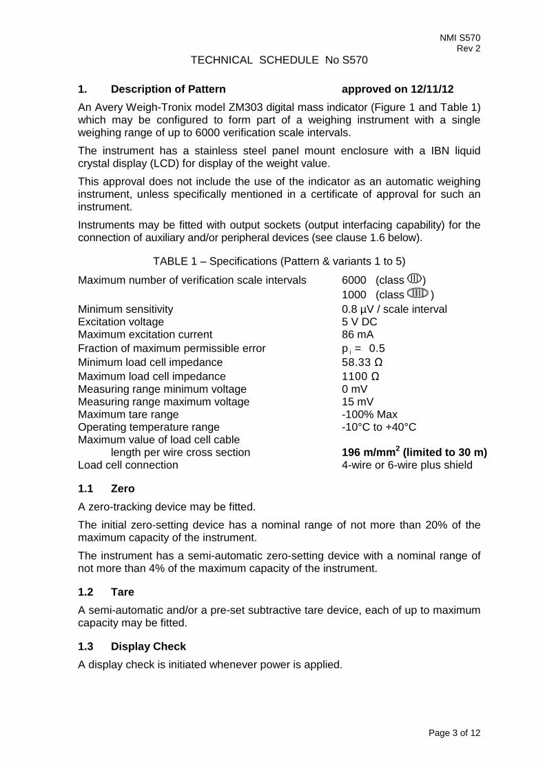
1. Description of Pattern approved on 12/11/12 An Avery Weigh-Tronix model ZM303 digital mass indicator (Figure 1 and Table 1) which may be configured to form part of a weighing instrument with a single weighing range of up to 6000 verification scale intervals. The instrument has a stainless steel panel mount enclosure with a IBN liquid crystal display (LCD) for display of the weight value. This approval does not include the use of the indicator as an automatic weighing instrument, unless specifically mentioned in a certificate of approval for such an instrument. Instruments may be fitted with output sockets (output interfacing capability) for the connection of auxiliary and/or peripheral devices (see clause 1.6 below).
TABLE 1 – Specifications (Pattern & variants 1 to 5)
Maximum number of verification scale intervals 6000 (class ) 1000 (class ) Minimum sensitivity 0.8 µV / scale interval Excitation voltage 5 V DC Maximum excitation current 86 mA Fraction of maximum permissible error p i = 0.5 Minimum load cell impedance 58.33 Ω Maximum load cell impedance 1100 Ω Measuring range minimum voltage 0 mV Measuring range maximum voltage 15 mV Maximum tare range -100% Max Operating temperature range -10°C to +40°C Maximum value of load cell cable
length per wire cross section 196 m/mm2 (limited to 30 m) Load cell connection 4-wire or 6-wire plus shield
1.1 Zero A zero-tracking device may be fitted. The initial zero-setting device has a nominal range of not more than 20% of the maximum capacity of the instrument. The instrument has a semi-automatic zero-setting device with a nominal range of not more than 4% of the maximum capacity of the instrument.
1.2 Tare A semi-automatic and/or a pre-set subtractive tare device, each of up to maximum capacity may be fitted.
1.3 Display Check A display check is initiated whenever power is applied.
Page 3 of 12

NMI S570 Rev 2
1.4 Power Supply Power supply may be either: • 12 – 36 V DC supplied by an AC/DC mains adaptor; or • batteries – typically a battery pack of 4 D cells. Note: The AC/DC mains adaptor supplied was an Operating Tech model OTE-60W-12 1 switch mode power supply (output 12 V DC, 5 A) – the submittor should be consulted regarding the acceptability of alternative power supply units.
1.5 Additional Features Other functions such as counting, setpoint, batching, peak hold, and checkweighing are available, however these are not approved for trade use.
1.6 Interfaces The indicator may be fitted with interfaces for the connection of auxiliary and/or peripheral devices. Any interfaces shall comply with clause 5.3.6 of document NMI R76 (the basic intent of which is that it shall not be possible to alter weighing results via the interfaces). Any measurement data output from the instrument or its interfaces shall only be used for trade in compliance with NMI General Supplementary Certificate No S1/0/B (in particular in regard to the data and its format). Indications other than the indications of measured mass (i.e. gross, tare, net, totals) displayed either on the indicator or on an auxiliary or peripheral device, are not for trade use. Instruments may be fitted with RS-232/RS422/RS485 serial data interface, Ethernet and USB interface, Wi-Fi, and may also have digital/analogue inputs/outputs associated with the set-point facility.
1.7 Markings and Notices Instruments carry the following markings:
Manufacturer’s mark, or name written in full Avery Weigh-Tronix Indication of accuracy class or Maximum capacity Max ..... kg #1 Minimum capacity Min ...... kg #1 Verification scale interval e = ....... kg #1 Maximum subtractive tare T = - ..... kg #2 Serial number of the instrument …........ Pattern approval mark for the indicator NMI No S570 Pattern approval mark for other components .............. #3
#1 These markings are shown near the display of the result. #2 This marking is required if T is not equal to Max. #3 May be located separately from the other markings. In addition, instruments not greater than 100 kg capacity carry a notice stating NOT TO BE USED FOR TRADING DIRECT WITH THE PUBLIC, or similar wording.
Page 4 of 12
NMI S570 Rev 2
1.8 Linearisation Facility Instruments are fitted with a linearisation correction facility having three correction points.
1.9 Verification Provision Provision is made for the application of a verification mark.
1.10 Software The software is designated AWT30-500161 version 1.x.x.x where x.x.x refers to the identification of non-legally relevant software. The instructions for accessing the software id are as follows (starting from the normal weighing mode): • Press and hold F1 key until PASS is displayed.
• Enter the password ‘111’ and press the ‘ZERO’ key to enter the USER menu level.
• Press the ‘UNITS’ key until ‘About’ is displayed and then press the ‘SELECT’ key.
• Press the ‘UNITS’ key until ‘FirM’ is displayed and then press the ‘SELECT’ key.
• Press the ‘SELECT’ key while ‘Partno’ is displayed and then press the ‘UNITS’ key. The firmware number is displayed; or
• Press the ‘UNITS’ key then press the ‘SELECT’ key while ‘VErSion’ is displayed. The software version is displayed.
• Press the ‘ZERO’ key and then press the ‘TARE’ key until ‘Save no’ is displayed.
• Press the ‘ZERO’ key to return to the normal weighing mode.
1.11 Sealing Provisions The indicator is sealed by installing a seal jumper on the mainboard and preventing access within the indicator housing. This may be achieved by applying destructible adhesive labels on opposite sides of a join in the indicator housing as shown Figure 2. It is possible to determine the seal jumper status as follows: • Press and hold the ‘F1’ key until PASS is displayed. • Enter the password ‘111’ and press the ‘ZERO’ key to enter the USER
menu level. • Press the ‘SELECT’ key and the ‘UNITS’ key three times until ‘SEAL’ is
displayed and then press the ‘SELECT’ key. • If the seal jumper is installed, the instrument will display ‘SEALEd’. In this
case the instrument may be verified. Otherwise the instrument will display ‘no SEAL’ in which case the instrument should not be verified until the seal jumper has been installed.
Page 5 of 12

NMI S570 Rev 2
Alternatively, the instrument is sealed by recording the audit trail counter on verification. The instrument automatically increments a configuration and/or calibration value (audit trail number) each time the indicator is re-configured and/or calibrated. The value(s) of these counters may be recorded on a destructible adhesive label attached to the instrument (e.g. as CONFIG x, CAL y). Any subsequent alteration to the calibration or configuration will be evident as the recorded values and the current counter values will differ. The instructions for accessing the configuration and calibration audit trail are as follows (starting from the normal weighing mode): • Press and ho ld ‘F1’ key un t il ‘PASS’ is d isp layed .
• Enter the password ‘111’ and press the ‘ZERO’ key to enter the USER menu level.
• Press the ‘UNITS’ key until ‘Audit’ is displayed and then press the ‘SELECT’ key twice.
• Press the ‘SELECT’ key while ‘ConFig’ is displayed. The ‘CONFIG’ counter value is displayed; or
• Press the ‘UNIT’ key then press the ‘SELECT’ key while ‘CALib’ is displayed. The ‘CAL’ counter value is displayed
• Press the ‘ZERO’ key and then press the ‘TARE’ key until ‘Save no’ is displayed.
• Press the ‘ZERO’ key to return to the normal weighing mode.
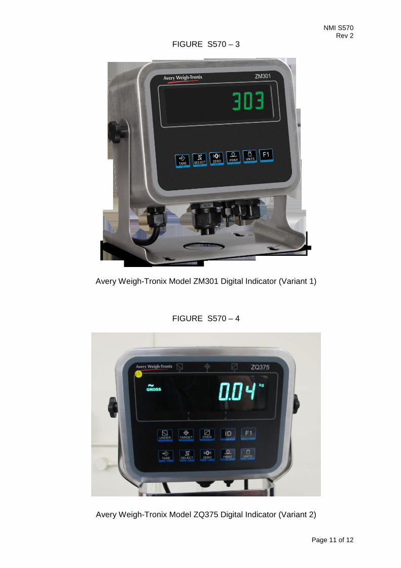
2. Description of Variant 1 approved on 12/11/12 The Avery Weigh-Tronix model ZM301 (Figure 3) which is similar to the pattern but having different operational keys and without numeric keypad.
3. Description of Variant 2 approved on 12/11/12 The Avery Weigh-Tronix model ZQ375 (Figure 4) which is similar to the pattern but without numeric keypad. Instruments may be fitted with a number of additional functions including under/over weight, target weighing and one of a several checkweighing applications, e.g. simple checkweighing (Sim375), mid-level checkweighing (Mid375), advanced checkweighing (Adv375), percentage checkweighing (Per375) and grading checkweighing (Grad375). These functions and displays are not approved for trade use. The instrument may be fitted with a ZQ-BAT battery pack.
4. Description of Variant 3 approved on 12/11/12 The pattern and variants with a stainless steel or alloy desktop/column mount enclosure. The stainless steel version may be used with a mains supply (110 – 240 V AC).
Page 6 of 12

NMI S570 Rev 2
5. Description of Variant 4 approved on 12/11/12
The p at t ern and var ian t s w it h a TN LCD instead of the IBN LCD display of the pattern.
6. Description of Variant 5 approved on 13/07/15
The p at t ern and var ian t s 1 t o 4 w it h AWT30-500161 software version 2.x.x.x (rather than version 1.x.x.x described for the pattern) where x.x.x refers to the identification of non-legally relevant software.
This software allows the same functionality as described for the p at t ern and var ian t s 1 t o 4.
7. Description of Variant 6 approved on 13/07/15 An Avery Weigh-Tronix model ZM305-SD1 digital mass indicator (Figure 5 and Table 2) which is similar to the pattern and may be configured to form part of: • A class weighing instrument with a single weighing range of up to
10 000 verification scale intervals; or • A class weighing instrument with a single weighing range of up to
1000 verification scale intervals.
The indicator operates from mains AC power (110 – 240 V AC, 50/60 Hz). TABLE 2 – Specifications for variant 6
Maximum number of verification scale intervals 10 000 (class ) 1000 (class )
Minimum sensitivity 0.5 µV/scale interval Excitation voltage 10 V DC Maximum excitation current 457 mA Fraction of maximum permissible error pi = 0.5 Minimum load cell impedance 21.87 Ω Maximum load cell impedance 1100 Ω Measuring range minimum voltage 0 mV Measuring range maximum voltage 15 mV Maximum tare range -100% Max Operating temperature range -10°C to +40°C Maximum value of load cell cable length per wire cross section 211 m/mm2 Load cell connection 4 or 6 wire plus shield
7.1 Software Version The software is designated AWT30-500161 version 2.x.x.x, where ‘x.x.x’ refers to the identification of non-legally relevant software. The instructions for accessing the software id are as follows (starting from the normal weighing mode) are the same as described for the pattern in clause 1.10 Software except that the ‘SETUP’ key is pressed wherever clause 1.10 refers to the ‘F1’ key.
Page 7 of 12

NMI S570 Rev 2
7.2 Sealing Provisions The sealing provisions are the same as described for the pattern in clause 1.11 Sealing Provisions except that the ‘SETUP’ key is pressed wherever clause 1.11 refers to the ‘F1’ key.
8. Description of Variant 7 approved on 13/07/15 An Avery Weigh-Tronix model ZM305-SG1 digital mass indicator (Figure 6) which has the same specifications and functions as the model ZM305-SD1 (variant 6) but in addition is provided with a GTN (Gross/Tare/Net) Inbound - Outbound vehicle weighing function.
8.1 GTN Inbound - Outbound Function The GTN Inbound - Outbound Function is intended specifically for truck weighing applications, including provision for vehicle identification data and pre-set tare values to be stored in memory. The GTN Inbound - Outbound Function provides for:
• Simple vehicle weighing, where the gross weight of a vehicle is determined by a single weighing;
• Inbound/outbound weighing, where a vehicle is weighed before and after a loading or unloading operation; and
• Weighing with pre-set vehicle weight, where the net weight of a vehicle is determined from the gross weighing operation and the application of a pre-set tare value.
Notes: The use of these features may or may not be appropriate in different situations. The acceptability in any particular situation must be assessed in-situ. In some situations it may be necessary for a print-out of the weighing result to be produced for the method of operation to be considered acceptable. In such situations General Supplementary Certificate No S1/0B should be consulted.
TEST PROCEDURE Instruments should be tested in accordance with any relevant tests specified in the National Instrument Test Procedures. The instrument shall not be adjusted to anything other than as close as practical to zero error, even when these values are within the maximum permissible errors.
Maximum Permissible Errors The maximum permissible errors are specified in Schedule 1 of the National Trade Measurement Regulations 2009.
Page 8 of 12

NMI S570 Rev 2
FIGURE S570 – 1
Avery Weigh-Tronix Model ZM303 Digital Indicator (Pattern)
Page 9 of 12
NMI S570 Rev 2
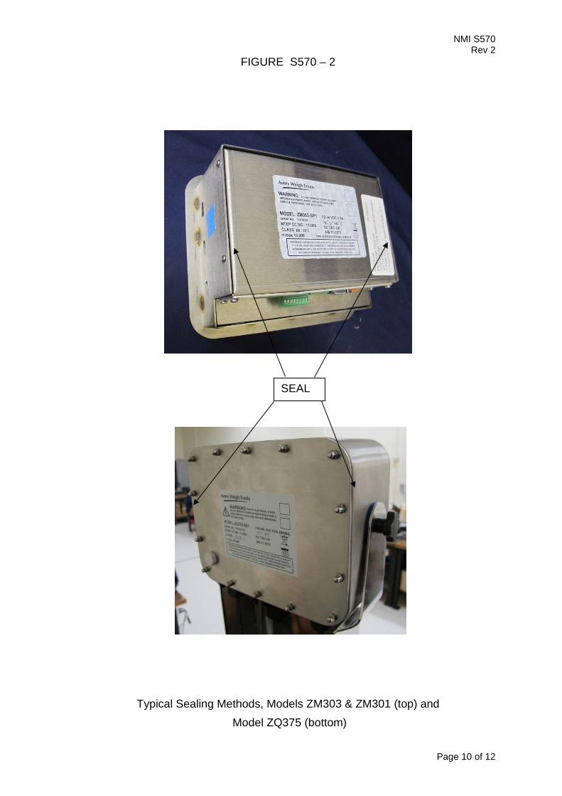
FIGURE S570 – 2
Typical Sealing Methods, Models ZM303 & ZM301 (top) and Model ZQ375 (bottom)
SEAL
Page 10 of 12
NMI S570 Rev 2
FIGURE S570 – 3
Avery Weigh-Tronix Model ZM301 Digital Indicator (Variant 1)
FIGURE S570 – 4
Avery Weigh-Tronix Model ZQ375 Digital Indicator (Variant 2)
Page 11 of 12

NMI S570 Rev 2
FIGURE S570 – 5
Avery Weigh-Tronix Model ZM305-SD1 Digital Indicator (Variant 6)
FIGURE S570 – 6
Avery Weigh-Tronix Model ZM305-SG1 Digital Indicator (Variant 7)
~ End of Document ~ Page 12 of 12