supplementary data 許容電流計算式 …permissible current calculation formula 公 式...
TRANSCRIPT

※本カタログの仕様・構成等は性能改善の為、お断り無く変更する場合がございます。※ This specification is subject to change without a prior announcement.
(2014.02)
許容電流計算式SUPPLEMENTARY DATA
許容電流計算式 PERMISSIBLE CURRENT CALCULATION FORMULA
公 式絶縁電線の許容電流 I は次の式で計算します。
I=η0
ここに I :許容電流(A) r :電線のT1 ℃における導体実効抵抗(Ω/cm) R :電線の全熱抵抗(℃cm/W) T1:電線の最高許容温度(℃) T :周囲温度(℃) η0:多条布設の場合の許容電流低減率
電線の導体抵抗 r は次により計算します。 r= r0{1+α(T1-20)} r0:電線の20℃における導体抵抗(規格値)(Ω/cm) α:導体温度抵抗係数(20℃のとき 銅 0.00393、アルミ 0.004)
電線の全熱抵抗Rは次により計算します。
R=R1+R2 R1= loge (℃cm/W)R2= (℃cm/W)
ここに、R1:絶縁体および被覆の熱抵抗(℃cm/W) R2:電線表面の熱抵抗(℃cm/W) d1:導体外径(mm) d2:電線外径(mm) P1:絶縁被覆の固有熱抵抗(℃cm/W) 表の値を用います。 P2:表面放散の固有熱抵抗(℃cm2/W)表の値を用います。
T1-TrR
P12π
10P2πd2
d2d1
FORMULAThe permissible current l of insulated wire is calculated by the following formula.
I=η0
Where, I :permissible current(A) r :Conductor effective resistance at T1 ℃ of electronic wire(Ω/cm) R :Full heat resistance of electronic wire (℃ cm/W) T1:Maximum permissible temperature of electronic wire(℃) T :Ambient temperature (℃) η0:Permissible current reduction coefficient in the case of multi-wire installation
The conductor resistance r of electronic wire is calculated by the following formula. r= r0{1+α(T1-20)} r0:Conductor resistance at 20℃ of electronic wire(standard value)(Ω/cm) α:Conductor resistance temperature coefficient (at 20℃ copper 0.00393 and aluminum 0.004)
The full heat of electronic wire R is calculatedby the following formulas.
R=R1+R2 R1= loge (℃cm/W)R2= (℃cm/W)
Where, R1:Heat resistance of insulation and covering(℃cm/W) R2:Heat resistance of electronic wire surface (℃cm/W) d1:Outer diameter of conductor(mm) d2:Outer diameter of electronic wire(mm) P1:Inherent heat resistance of insulation (℃cm/W) The value in the table is used. P2:Inherent heat resistance of surface diffusion(℃cm2/W) The value in the table is used.
T1-TrR
P12π
10P2πd2
d2d1
P2 の表 表面放散固有熱抵抗Table of P2 Inherent Heat Resistance of Surface Diffusion
P1 の 表のものTHOSE IN THE TABLE OF P1
500+10d2(d2 < 40 )
400+20d2(d2 < 20 )含浸編組IMPREGNATED BRAID
材料名MATERIAL P2(℃ cm2/W )
S=d 1.00 0.85 0.80 0.70 0.70 0.60 ー ー ーー 0.95 0.95 0.90 0.90 0.90 0.85 0.80 0.80ー 1.00 1.00 0.95 0.95 0.95 0.90 0.85 0.85
S=2dS=3d
最高許容温度Maximum Permissible Temperature
多条布設の場合の許容電流低減率η 0Permissible Current Reduction Coefficient η 0 of Multi-wire Installation
一般 PVCGENERAL PVC
PEイラックス ®AIRRAX™A
イラックス ®B28、B32IRRAX™B28, B32
イラックス ®B30IRRAX™B30
イラックス ®V2IRRAX™V2
AEX-28FEPTFE
耐熱 PVCHEAT RESISTANT PVC
60
1 2 3 6 4 6 8 9 12η 0条 数
NUMBER OF WIRES配 列
ARRANGEM-ENT中心間隔
CENTRAL INTERVAL75
90
125
150
105
140200250
80.105
材料名MATERIAL T1(℃)
S S S SS
S
SS
※弊社 Web サイトで許容電流値を算出できます。http://www.sei.co.jp/ewp/J/
P1 の固有熱抵抗(℃ cm/W )Table of P1 Inherent Heat Resistance(℃ cm/W)
PVC 600450450400
450
PETFE
FEP・IRRAX R9、ETFEナイロンNYLON
材料名MATERIAL P1(℃ cm/W )

※本カタログの仕様・構成等は性能改善の為、お断り無く変更する場合がございます。※ This specification is subject to change without a prior announcement.
(2014.02)
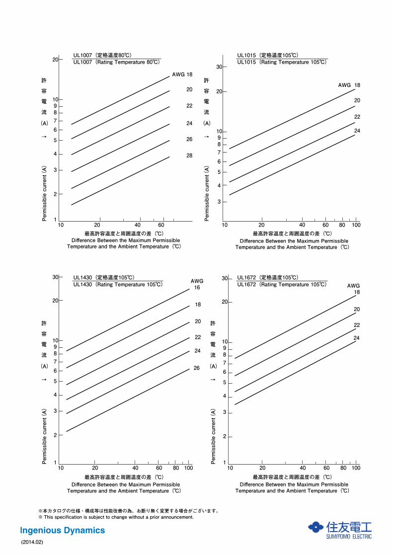
各種電線の許容電流Permissible Current of Various Kinds of Electronic Wires
10 20 40 60 80 100
2
3
4
5678910
20
30
40
5060
最高許容温度と周囲温度の差(℃)
イラックス®A電線(定格温度90℃)IRRAX™A electronic wire(Rating Temperature 90℃)
Difference Between the Maximum PermissibleTemperature and the Ambient Temperature(℃)
Permissible current(A)
UL3385(Rating Temperature 105℃) UL3385(定格温度105℃)
UL10368(Rating Temperature 105℃) UL10368(定格温度105℃)
〈PS〉E
許
容
電
流
→
(A)
3.5sq
2.0sq
1.25sq
0.75sq
0.5sq
0.3sq
0.2sq
UL3443(定格温度105℃)
10 20 40 60 80 100
2
1
3
4
5678910
20
15
UL3443(Rating Temperature 105℃)
AWG 20
AWG 22
AWG 24
AWG 26
AWG 28
AWG 30
最高許容温度と周囲温度の差(℃)Difference Between the Maximum PermissibleTemperature and the Ambient Temperature(℃)
Permissible current(A)
許
容
電
流
→
(A)
Permissible current(A)
許
容
電
流
→
(A)
最高許容温度と周囲温度の差(℃)Difference Between the Maximum PermissibleTemperature and the Ambient Temperature(℃)
Permissible current(A)
許
容
電
流
→
(A)
最高許容温度と周囲温度の差(℃)Difference Between the Maximum PermissibleTemperature and the Ambient Temperature(℃)
20 40 60 80 100101
2
3
4
5678910
AWG24
AWG26
AWG28
AWG30
AWG32
10 20 40 60 80 1001
2
3
4
5
678910
20 AWG18
AWG20
AWG22
AWG24
AWG26
※本カタログの仕様・構成等は性能改善の為、お断り無く変更する場合がございます。※ This specification is subject to change without a prior announcement.
(2014.02)
UL1672(定格温度105℃)UL1672(Rating Temperature 105℃)UL1430(Rating Temperature 105℃)
UL1007(定格温度80℃)
10 20 40 60
2
1
3
4
5
678910
20
AWG 18
20
22
24
26
28
UL1430(定格温度105℃)
10 20 40 60 80 100
2
1
3
4
5
678910
20
30
22
24
26
10 20 40 60 80 100
2
1
3
4
5
678910
20
30AWG 18
20
22
24
UL1015(定格温度105℃)
10 20 40 60 80 100
3
4
5
678910
20
30
AWG 18
20
22
24
最高許容温度と周囲温度の差(℃)Difference Between the Maximum PermissibleTemperature and the Ambient Temperature(℃)
最高許容温度と周囲温度の差(℃)Difference Between the Maximum PermissibleTemperature and the Ambient Temperature(℃)
Permissible current(A)
許
容
電
流
→
(A)
Permissible current(A)
許
容
電
流
→
(A)
Permissible current(A)
許
容
電
流
→
(A)
Permissible current(A)
許
容
電
流
→
(A)
最高許容温度と周囲温度の差(℃)Difference Between the Maximum PermissibleTemperature and the Ambient Temperature(℃)
最高許容温度と周囲温度の差(℃)Difference Between the Maximum PermissibleTemperature and the Ambient Temperature(℃)
UL1007(Rating Temperature 80℃) UL1015(Rating Temperature 105℃)
AWG16
18
20

※本カタログの仕様・構成等は性能改善の為、お断り無く変更する場合がございます。※ This specification is subject to change without a prior announcement.
(2014.02)
周囲温度(℃)
各種電線の許容電流(0.5mm2)Permissible Current of Various Kinds of Electronic Wires(0.5mm2)
Ambient Temperature(℃)
-20 00
2
4
6
8
10
12
14
16
18
20
22
20 40 60 80 100 120 140 160-40
Permissible current(A)
許
容
電
流
(A)
AEX-30(耐熱150℃)(Temp. class 150℃)
AEX-30(耐熱150℃)(Temp. class 150℃)
AEX-28(耐熱140℃)(Temp. class 140℃)
AEX-28(耐熱140℃)(Temp. class 140℃)
AEX(耐熱120℃)(Temp. class 120℃)
AEX(耐熱120℃)(Temp. class 120℃)
AVX(耐熱100℃)(Temp. class 100℃)
AVX(耐熱100℃)(Temp. class 100℃)
Permissible current(A)
許
容
電
流
(A)
周囲温度(℃)
各種電線の許容電流(8mm2)Permissible Current of Various Kinds of Electronic Wires(8mm2)
Ambient Temperature(℃)
-20 00
120
110
100
90
80
70
50
40
30
20
10
60
130
20 40 60 80 100 120 140 160-40
AEX-30(耐熱150℃)(Temp. class 150℃)
AEX-30(耐熱150℃)(Temp. class 150℃)
AEX-28(耐熱140℃)(Temp. class 140℃)
AEX-28(耐熱140℃)(Temp. class 140℃)
AEX(耐熱120℃)(Temp. class 120℃)
AEX(耐熱120℃)(Temp. class 120℃)
AVX(耐熱100℃)(Temp. class 100℃)
AVX(耐熱100℃)(Temp. class 100℃)