supplementary guidance to tgd b (fire safety) volume 2
TRANSCRIPT
1
Supplementary Guidance to
TGD B (Fire Safety) Volume 2-
Dwelling Houses 2017
Prepared by the Department of Housing, Planning and Local Government housing.gov.ie
Guidance on Fire Resistance of Walls,
Intermediate Floors, and Trussed Roofs in
dwellings
© Government of Ireland 2020
1st Edition
1
Introduction
The Building Regulations 1997 - 2019 set out the minimum legal requirements that must be complied with to ensure the safety and welfare of people in and about buildings. The Building Control Act 1990 - 2014 places a statutory obligation on owners, designers and builders to design and build works or buildings in accordance with the requirements of the Building Regulations. The adoption of the Eurocodes as the appropriate suite of standards for the structural design of buildings/ structural elements inherently means that the fire performance of such works must be demonstrated using European test standards (EN). Part B - Fire Safety of the Second Schedule to the Building Regulations was revised in 2017 to include provisions specifically for dwelling houses. Technical Guidance Document B Volume 2 - Dwelling houses (TGD B - Fire Safety Volume - 2 Dwelling houses 2017) was published in 2017 to support Part B and to give guidance on prima facie compliance with Part B of the Building Regulations. Where buildings are designed in accordance with the Eurocodes and are required by Part B of the Building Regulations to have a fire performance then this fire performance, specified under TGD B, 2017 must be demonstrated in accordance with the European test methods.
Purpose
The purpose of this supplementary guidance document is to support compliance with the fire resistance provisions as specified in Technical Guidance Document B Volume 2 - Dwelling houses (TGD B - Fire Safety Volume - 2 Dwelling houses 2017).
Fire Resistance
There is often confusion between Fire Resistance and Reaction to Fire. Fire resistance is the measurement of the ability of a material or system to resist, and ideally prevent, the passage of fire from one distinct area to another. Reaction to fire is the measurement of how a material or system will contribute to the fire development and spread. While individual products used in construction e.g. plasterboard, timber, steel, aluminum, etc. will have a “Reaction to Fire” designation based on various tests1
carried out, this does not mean that the construction has a fire resistance.
1 I.S. EN ISO 1182:2010 Reaction to fire tests for building products - Non-combustibility test.
I.S. EN ISO 1716:2010 Reaction to fire tests for building products - Determination of the gross calorific value.
I.S. EN 13823:2010 Reaction to fire tests for building products - Building products excluding floorings exposed to the
thermal attack by a single burning item.
I.S. EN ISO 11925-2:2010 Reaction to fire tests for building Products, Part 2 - Ignitability when subjected to direct
impingement of a flame.

2
Constructions requiring fire resistance must be considered against various criteria in relation to their fire resistance for standard fire exposure. These are: R – mechanical resistance i.e. an ability to maintain loadbearing capacity,
E – integrity i.e. an ability to maintain the integrity of the structure,
I – insulation i.e. an ability to provide insulation from high temperatures.
Therefore the fire resistance of any construction is a result of the combination of the materials used, including their thickness, spacing and fixing of the materials (see Appendix A), together with the workmanship employed during assembly. In order to claim a specific fire resistance for a load bearing construction, it must be proven by test to the European test method, EN 1365 (series) Fire resistance tests for load bearing elements.
3
Guidance on Walls Introduction
External walls are being designed to achieve lower U-values and give greater air tightness than previous practice, due to Nearly Zero Energy Buildings (NZEB) requirements. This has resulted in some walls being constructed using internal insulation or in some cases thicker walls with service voids with or without internal insulation.
As walls are a structural element, and therefore, their design is to the Eurocodes. Accordingly, the fire resistance of the walls must be proven by test to the European Test method, EN 1365 (series).
Fire resistance tests for load bearing elements.
It should be noted that the exemption given in section 3.4.4 (a) of TGD B, 2017 “a structure that only supports a roof,” only applies to the immediate structure below the roof covering and does not extend to the walls supporting the roof construction.
Masonry walls
Traditional masonry construction (dense aggregate masonry), should be designed
and built (using proper materials and workmanship) in accordance with I.S. EN
1996 (series) (in conjunction with the Irish National Annexes) and additional
guidance given in SR 325.
The fire resistance of a masonry wall is dependent on the thickness of the masonry
element. The thickness required to achieve an REI 30 is specified in Tables NA.3.2
and NA.3.6 of the Irish National Annex to I.S. EN 1996-1-2. For fully loaded dense
aggregate concrete masonry to achieve a fire resistance of REI 30, the minimum
thickness should be 90mm.
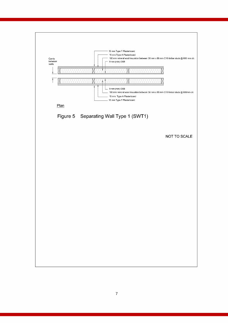
Timber Frame walls
Fire tests on generic external and separating (party) wall constructions were commissioned by the Timber Frame Industry in conjunction with the Irish Timber Frame Manufacturers Association (ITFMA) and the fire tests conducted in accredited laboratories in accordance with the appropriate European Test method for load bearing walls. Constructions which met a fire resistance for external walls of REI 302 and a separating (party) wall of REI 602 by fire test are detailed below. The axial loads applied during the test were: 7KN per stud where 89mm studs were used, and 11KN per stud where 138mm studs were used. The maximum stud centres tested were 600mm c/c.
2 See appendix A of TGD B fire Safety Volume 2 Dwelling Houses

4
Walls constructed in the manner shown below must be in accordance with the structural engineer’s design and timber frame manufacturer’s specifications. It should be noted that the thickness of the structural components may be increased but not decreased. Insulation thickness may vary but the maximum thickness of the continuous insulation should not exceed 50mm. Note: In the case of all separating walls the build-up, including linings must be carried out in the factory, weather protected and delivered to site. Jointing strips may be fixed on site where butt joints (Horizontal or vertical) occur.

5

6
7
8
Guidance on Intermediate Timber Floors in Dwellings
Introduction
Floors are a structural element and their design should be to the Eurocodes. Therefore, the fire resistance of the floors must be proven by test to the European Test method, EN 1365 (series)
Fire resistance tests for load bearing elements.
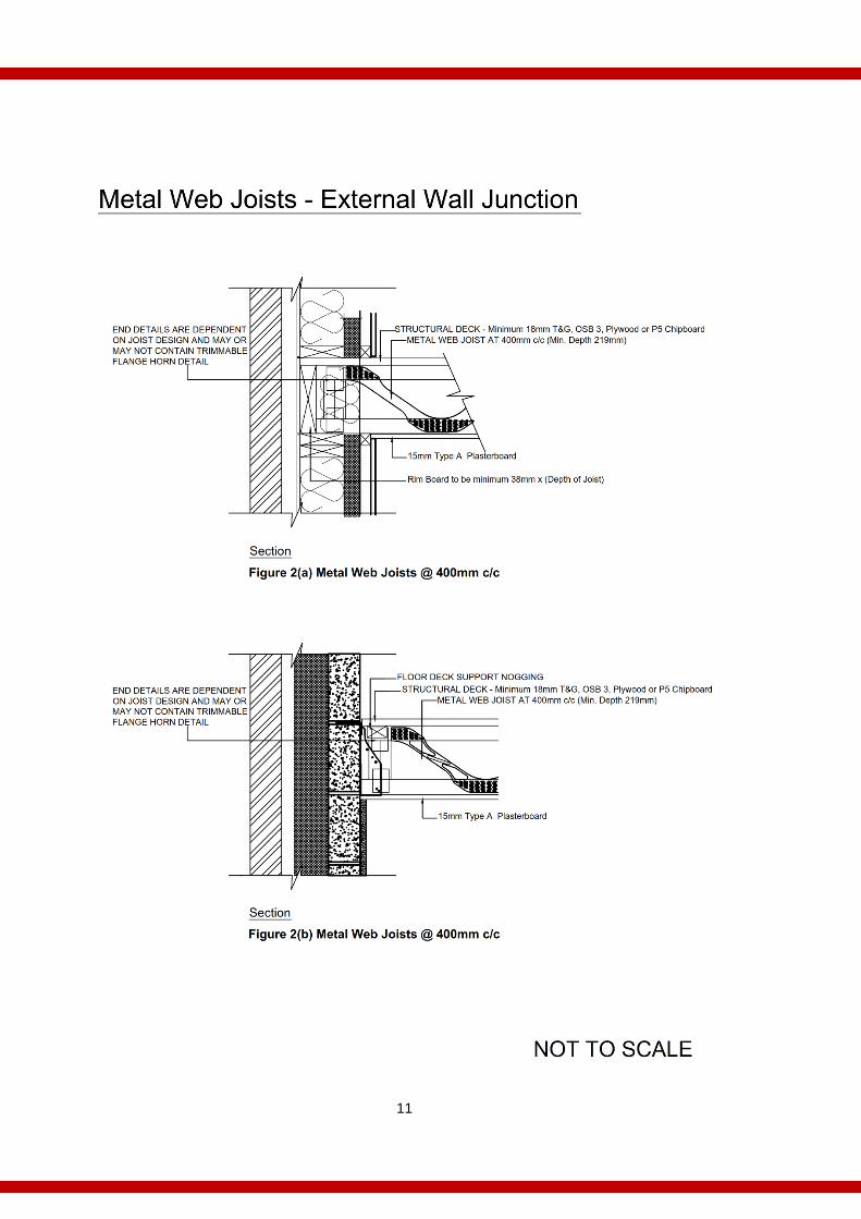
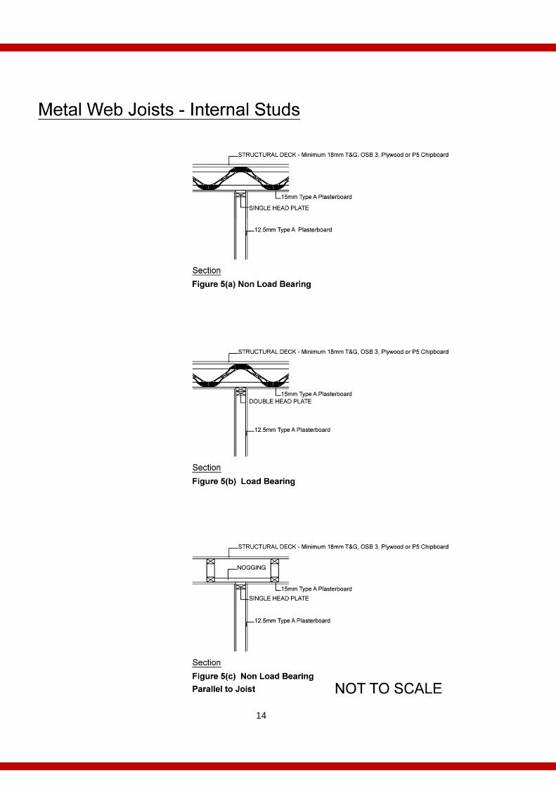
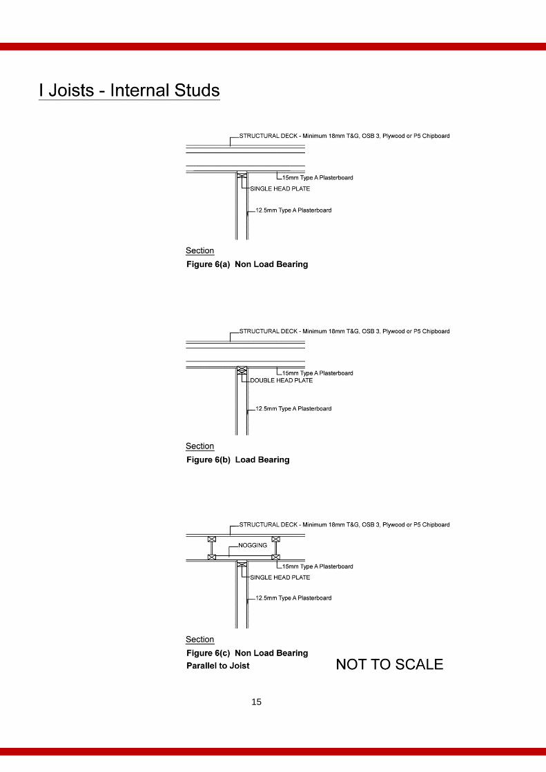
Fire tests on floor constructions using different type joists (@ 400mm c/c (max)) - solid, metal web and timber web, have been carried out by the Trussed Rafter Association, Irish Timber Frame Manufacturers Association and Gypsum Industry, in accredited laboratories in accordance with the appropriate European Test method for load bearing floors. Constructions which have met the required fire resistance for floors in dwelling houses (REI 30), when loaded in accordance with the design imposed load of 1.5 kN /m2,(UDL) by fire test are detailed below. Where loadbearing studs are used to support a floor, the stud must also have the same fire resistance as required for the floor (see Figure 4b, 5b, and 6b below, which meet the requirements for REI 30, with studs at 400mm c/c (max)).
Floors with open void space
Where floors are constructed to have open void space for the provision of services by the use of “Engineered Joists” or counter battens below traditional solid joists the risk of fire spread within the floor void is greatly increased. Penetrations, such as down-lighters, soil vent pipes or ventilation duct heads, in the plasterboard create vulnerability in the ceiling and as such must be fire stopped by the use of fire collars, fire hoods or fire rated products.
External Wall/Floor Junction – Internal Insulation
Where internal insulation is provided on an external wall, care needs to be taken to ensure that there is no route for fire spread in a hidden space, between the wall and the floor void. Where a service void is created in the wall build-up, fire stopping, such as a batten not less than 38 mm is necessary at the top of the void. Where continuous insulation with a reaction to fire classification of less than A2, in accordance with EN 13501-1 Fire classification of construction products and building elements – Part 1: Classification using data from reaction to fire tests, is used on the face of the wall, fire stopping is achieved by a combination of timber battens (min 38mm thick), and / or the use of insulation in the floor void which has a classification of A2 or better.

9
Plasterboard substitution
All plasterboards used in the fire tests are classified in accordance with EN 520 Gypsum plasterboards – Definitions, requirements and test methods. Type F plasterboard may be used where Type A plasterboard is specified, as long as the thickness of the board is not less than the thickness as specified in this guidance, unless otherwise indicated, e.g. solid joists. A reduction in the thickness of the plasterboard, or a substitution to a board not classified under EN 520, is not acceptable unless the build-up has been proven by test in accordance with the EN 1365 (series).

10
11

12

13
14
15

16
Guidance on Timber Roof Trusses in Dwellings
Introduction
Roofs are a structural element and their design should be in accordance with the Eurocodes. The fire resistance of the roof, where there is a requirement, must be proven by test to the European Test method, EN 1365 (series) Fire resistance tests for load bearing elements.
Requirement for fire resistant construction in truss roofs
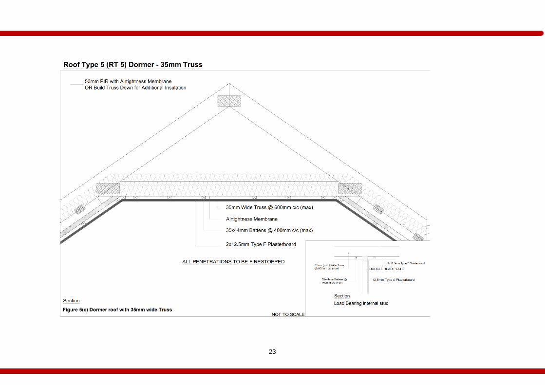
TGD B 2017, Diagram 11 provides two options for protecting the escape stairway. Truss design requires that all the elements of the truss (chord and web members) are intact in order to maintain the integrity of the whole truss. As such, Option 11(b) (fire resisting ceiling) is the appropriate solution for a trussed roof design. Where there is a fire requirement it applies from the habitable area. This would typically be from the underside of the bottom chord of the truss roof, but in the case of a dormer roof this would also be from the habitable area in the attic. Typically there are three scenarios where the truss roof may need fire resistance: 1. Where there is a requirement for a protected stairway, such as in a dwelling
house with three or more storeys, a truss roof must form part of a fire resistant construction as failure of the truss would compromise the protected escape route.
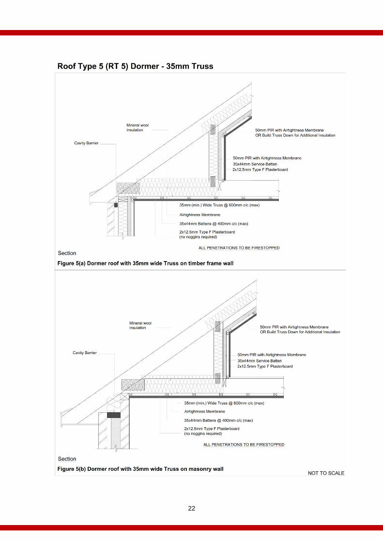
2. Where “Attic” type trusses, commonly called dormer trusses are forming the floor
in the dormer area, the floor formed by the truss is required to have a fire resistance. The required fire resistance will depend on the height of the floor above ground level i.e. R 30, REI 15 or REI 30. As the integrity of the truss depends on all elements remaining intact the fire resistance required for the floor will also apply to the walls and ceiling in the dormer area as well as the ceiling below the dormer area.
3. Where a roof serves as an escape route from an upper storey, the roof must have
a fire resistance from the underside.
The fire resistance of any such roof is a result of the combination of the design, the materials used (trusses, noggins, linings etc.), including their thickness, spacing and fixing of the materials i.e. the build-up, together with the workmanship employed during assembly.
Fire Resistance Tests The Trussed Rafter Association, the Irish Timber Frame Manufacturers Association
and the Timber Frame Industry commissioned fire tests on a variety of build-ups on
timber truss roofs. These fire tests were carried out in accredited laboratories in
accordance with the appropriate European Test method for load bearing elements

17
(EN 1365). The fire tested roof build-ups involved load bearing timber trusses of
different chord and web thicknesses, affixed with varying combinations of single or
double plasterboard slabs, with and without battens or noggins. Trussed roofs were
tested in accordance with EN 1365 Part 2 with loads applied to induce stresses that
would reflect a typical truss roof loaded with tiles and an imposed load of 0.75KN/m2
on rafters and a service load of 0.25KN/m2 on the ceiling joist.
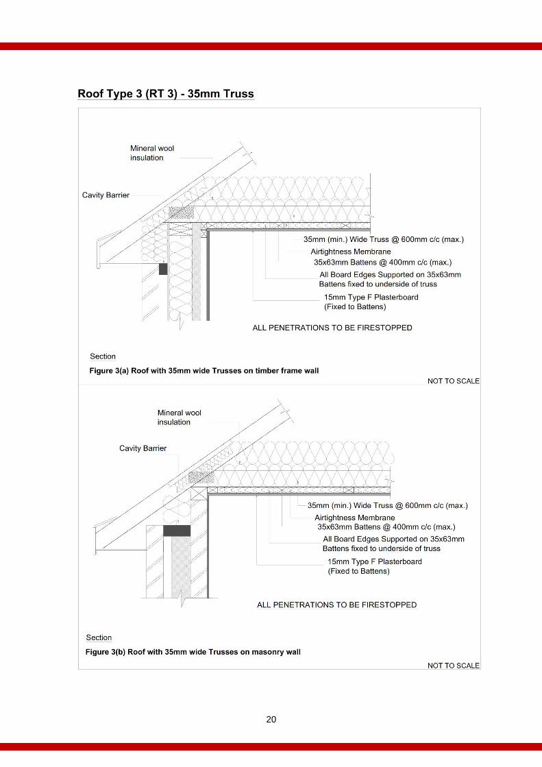
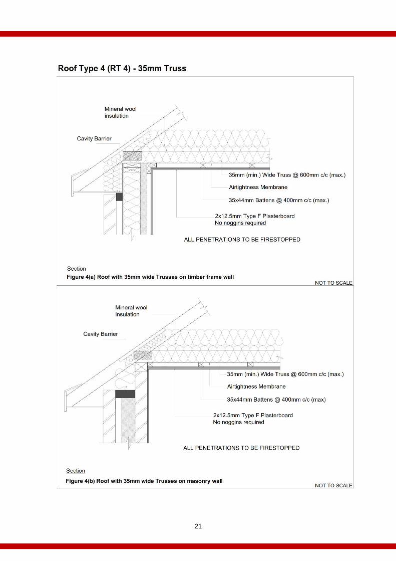
Roof build-ups which met a fire resistance of 30 minutes (REI 30), by fire test are detailed below.
External Wall / Roof Junction – Internal Insulation
Where internal insulation is provided on an external wall, care needs to be taken to ensure that there is no route for fire spread in a hidden space, between the wall and the roof void. Where a service void is created in the wall build-up, fire stopping, such as a batten not less than 38 mm is necessary at the top of the void. Where continuous insulation with a reaction to fire classification of less than A2, in accordance with EN 13501, is used on the face of the wall, fire stopping is achieved by a combination of timber battens (min 38mm thick), and / or the use of insulation in the roof void which has a classification of A2 or better.
Fire resistant roof build-ups with penetrations
All penetrations, such as sockets, switches, down-lighters, soil vent pipes, ventilation duct heads, etc., in the plasterboard “creates” vulnerability in the fire resistant construction and as such must be fire stopped by the use of fire collars, fire hoods or fire rated products. An exception to this requirement is sockets or switches in the vertical wall section of a dormer roof truss. The provision of a service void below an imperforate ceiling in any roof may avoid the need for fire stopping (see figure 2 (a) & 2 (b)). Note: Where loadbearing studs are used to support a truss roof, the stud must also have the same fire resistance as required for the truss.

18

19
20
21
22
23

24

25

26
Appendix A - Fixings
Introduction
Plasterboard to EN 520 Gypsum plasterboards – Definitions, requirements and test methods forms a critical part of any fire resisting build up. The following table provides details of the fixings required to achieve the specified fire resistances.
(1) All edges supported by timber and fixed (2) Edges fixed only where backed by timber (3) Where backed by joists
Fixings
Element Description Plasterboard
Type Screw length Max Centres
(Perimeter / Internal)
Wal
ls
WT1, WT2, WT3, WT4
External Walls (REI 30)
(600mm c/c)
15mm Type A 42mm 200mm / 300mm (1)
SWT1 Separating Walls (REI 60)
15mm Type A & 15mm Type F
50mm (Type A) Board 65mm (Type F) Board
200mm / 300mm
Figure 4b, 5b, 6b
Loadbearing Stud (REI 30) (400mm c/c)
12.5mm Type A 42mm 300mm / 300mm
Flo
ors
Figure 1
Solid Joist Floor 15mm Type A or 12.5mm Type F
42mm 150mm (3)
Figure 2
Metal Web Joist 15mm Type A 55mm 150mm(3)
Figure 3
I-Joist 15mm Type A 42mm 150mm(3)
Tru
sse
s
RT1, RT2, RT3, RT6
Truss Roof / Dormer Roof
15mm Type F 42mm 150mm (1)
RT4, RT5
Truss Roof / Dormer Roof
2 x 12.5mm Type F 42mm / 60mm 150mm (2)

27

Department of Housing, Planning and Local Government
housing.gov.ie