support creation - uk.3dsystems.com€¦ · 3dxpert support creation & verification – 6...
TRANSCRIPT

Support Creation Template Based Creation of Supports
TutorialV3-13,0600,1489,1604(SP6)

3DXPERT Support creation & Verification – 2 Template based creation of supports
In this exercise, we will learn the foundation of Template based creation of supports.
This exercise is based on the Automatic region creation exercise.
Automatic region creation is done as the first stage in the Support Manager tool, in order to
identify those regions, curves and points. On these regions, we will build the support structure. The
Support Manager is activated from the 3D Printing Process Guide.
To use this command we need to follow few steps (guided):
Open downloaded 3D Printing Project from the Initial screen.
Note that Automatic region creation is already done.
Create some supports from the Support Manager using templates
! Notice/ Remember
Left mouse button name is "pick"
Middle mouse button name is "Exit"
Right mouse button name is "Click"
1. From the Initial screen pick Open File.
2. This command will open the 3DXpert for SOLIDWORKS Explorer. Load project file Manifold Project region creation Result from the same folder where downloaded files.
Note: it is possible to use – if done - the project result from 3DXpert- Support creation & Verification -
Automatic region creation exercise.
Open File

3DXPERT Support creation & Verification – 3 Template based creation of supports
After the file is open, the screen will look like this: Regions are predefined and marked in yellow.
3D Printing Process Guide
3DP Objects Tree
3DP Objects Tab
Display Area
Support Manager Tool
Part on Tray

3DXPERT Support creation & Verification – 4 Template based creation of supports
3. Pick the Support Manager tool.

3DXPERT Support creation & Verification – 5 Template based creation of supports
The Support Manager table is open. All regions analyzed at 50° overhang are listed.
1. Table of regions created on this part. Every row describes a different region with its parameters and
supports (at this stage, no support is yet defined).
Region Type indicates whether a region is Closed or Open.
Some types of supports (like Wall) might change the region from Closed to Open.
Support Type describes the family name of build support like: Solid, Wall, Cone, Lattice and more
Analysis Angle displays the overhang angle in Create Region stage.
Min. Height displays the minimum distance from tray to lowest point on region.
2D Area displays the projected area of a region on tray.
Ease of Removal indication. The scale is from 0 to 1. Where 0 is most difficult to remove and all the
range up to 1 which is the easier to remove.
2. Select Template. Opens a list of pre-defined supports to apply to selected region. Alternatively, click
the Browse button to launch the Load Template dialog. This has the advantage of an image
describing each template.
3. Visibility buttons for regions and supports.
4. Dialog settings. Column chooser, multi sorting table, save and load preferred table look.
5. Meta Templates. Automatic use of smart templates to perform single operation to create supports
(Meta Templates will be discussed in a separate exercise).
6. Template By Reference creates the same supports, as already created on reference (user picked)
regions. (with option to edit tilt and shrink)
7. Create Regions. Runs Create regions (for example, if the existing regions were deleted by the user).
Note that if regions are already created, Create Regions will result in duplicated regions.
! Please notice: We recommend to have the 3DXpert Support Structures – Standard Naming Convention in hand for a better understanding supports names.
1
2
3 4
5
7
6

3DXPERT Support creation & Verification – 6 Template based creation of supports
4. Pick Region 5 from the screen or from the table.
This region is located at the center of the part as well as the base of part, so it may require some
massive holding – let's look for a "Solid Support".
From the list of supports in the Select Template pick SOLD_F_XY10W03A45
After picking this support, a new support is added on that region.
5. Pick Region 4 from the screen or from the table.
This region is also located at the center of the part and may require massive holding, but we can consider it less massive then the first one – let's look for another "Solid Support".
From list of supports in the Select Template pick SOLD_F_XY05W03A45
After picking this support, a new support is added to that region.

3DXPERT Support creation & Verification – 7 Template based creation of supports
Looking from the bottom (-Z direction) it is possible to see that the first solid support is massive than the second Solid Support. The names of supports are codded. In this case SOLD means Solid support. The F means that the solid have Fragmentation. In general the difference between them is the size of the solid, the first one XY10 means square of 10 mm and the second one XY05 means square of 5 mm.
Note on the Table of regions that Region a bulb was added automatically to indicate that a support was added on this region. The bulb of this region itself is now in Hide mode (as this region is no longer required) while the bulb of the relevant support turns to Show mode.
Hide or Show Support
Hide or Show Region
Region Type
SOLD_F_XY10W03A45
SOLD_F_XY05W03A45
Type of Support

3DXPERT Support creation & Verification – 8 Template based creation of supports
6. Pick Region 3 from the screen or from the table.
From the table seen above, this region has a 2D Area (projected area on tray) of around 1550 mm²
and is a light structure. In this case we can consider also a light structure of support - let's look for "Wall Support".
Click the Browse button to launch the Load Template dialog. Pick one of the Wall supports – in this case WALL_HSG_F_B_TH00_P-2S_T_M1
This family of supports can give a very good cover for small up to large regions with a good strength and yet easy to remove because of the "Teeth" (T in the code name) at the touch points with the part. A view from bottom:

3DXPERT Support creation & Verification – 9 Template based creation of supports
7. Pick Region 1 from the screen or from the table.
This region is also located at the center of the part and may require massive holding, but we can consider less massive then the first one – let's look again for a "Solid Support". Notice the detail (Region 2) under this wing.
From the Supports Manager window pick Template By Reference command then pick desired support from screen as reference (Region 3). This option creates similar supports very quickly. With this option you can pick as many regions as needed, and these will get the support based on the same reference (picked) support.
Let's have a look from bottom. Clik on Region 1 in the table to sub menu. From the sub menu pick Edit Tilting.
Reference region
New region
Notice the detail
(Region 2)

3DXPERT Support creation & Verification – 10 Template based creation of supports
From the window that was opened pick Tilt & scale.
This will allow us to move the support on the tray and if necessary to scale and shrink it so it won't gauge with the part. Pick & drag the Pink Point in the arrow direction as shown.
While dragging the Overhang angle is analyzed and result shown on the label attached to the Angle line.
Since 50° Overhang angle was used any tilt under this angle might cause a need to support the support itself. In such case happens, the Angle line becomes Red.
Pick anywhere on the Angle Line, a Red Point appear. It is possible to drag it to any direction as well add scaling to the support’s section. It is also possible to pick the point at tray level (Pink Point) to move and scale it as well if needed. By doing so, we released the detail so the support won't relay on it on the upper side.
OK in Feature Guide to keep tilting.
Pink Point
Angle Line
Pink Point

3DXPERT Support creation & Verification – 11 Template based creation of supports
8. Pick Region 2 from the screen or from the table.
This region is small and very light – let's try for that a "Cone Support". For a better view Hide Region 1 using the bulb.
From the list of supports in the Select Template (or lunch Load Template dialog) pick
CONE_D15XY20_HS
This support has a ball shape at touch points with the part to ease the removal.
After picking this support, a new support is added to that region.
It is also possible to tilt the Cone Support to minimize touching with the side of the part.
OK in Feature Guide to keep tilting.

3DXPERT Support creation & Verification – 12 Template based creation of supports
9. Pick Region 6 from the screen or from the table.
Similarly to Region 1, this region has a 2D Area (projected area on tray) of around 1635 mm²
and a light structure. In this case we can consider also a light structure of support - let's look now for "Lattice Support".
From list of supports in the Select Template (or lunch Load Template dialog) pick
LATT_B_D05L20
This family of supports can give a very good cover for small medium up to very large regions with a good strength and yet easy to remove because of the Ball (B in the code name) shape at touch points with the part.
After picking this support, a new support is added to that region.
From a close look it is possible to see the light but yet strong structure of the Lattice Support.
3DXPERT Support creation & Verification – 13 Template based creation of supports
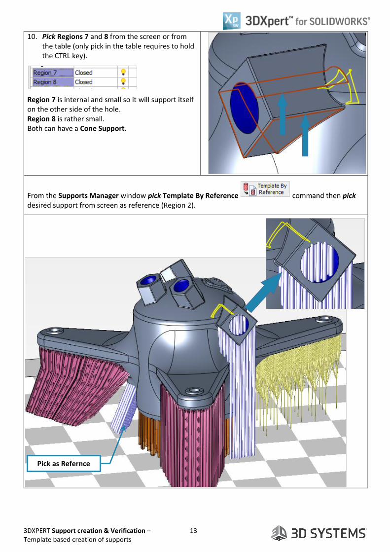
10. Pick Regions 7 and 8 from the screen or from the table (only pick in the table requires to hold the CTRL key).
Region 7 is internal and small so it will support itself on the other side of the hole. Region 8 is rather small. Both can have a Cone Support.
From the Supports Manager window pick Template By Reference command then pick desired support from screen as reference (Region 2).
Pick as Refernce

3DXPERT Support creation & Verification – 14 Template based creation of supports
11. Regions 9 is completely internal and hence, removal is very difficult.
In the Support Manager we can see the Ease of Removal indication. The scale is from 0 to 1. Where 0 is most difficult to remove and all the range up to 1 which is the easier to remove.
This region got 0.94, so a light support like the first one we use will be good and reachable from both sides of the hole. This support has Teeth on both sides.
From the Supports Manager window pick Template By Reference
command then pick the required support from screen as reference (Region 3).
Notice on the left side on the 3DP Objects Tab, each region and support that was build get its own leaf on the Objects tree. From that row it is possible to hide or show, to set a render mode (Solid, Transparent, and Wireframe) and to change color.
End of Exercise.
Pick as Refernce