supporting interdisciplinary healthcare team … interdisciplinary healthcare team dynamics with...
TRANSCRIPT

Supporting Interdisciplinary Healthcare
Team Dynamics with Business Process
Management
Nihan Catal
Thesis submitted to the
Faculty of Graduate and Postdoctoral Studies
in partial fulfillment of the requirements for the degree of
Master of Science in Systems Science
University of Ottawa
Ottawa, Ontario, Canada
May 2016
© Nihan Catal, Ottawa, Canada, 2016
Abstract ii
Abstract
[Context] Interdisciplinary healthcare teams (IHTs) include practitioners from different
disciplines who collaborate for providing care to patients. IHTs often follow clinical
workflows composed of tasks that must be executed by practitioners with specific capa-
bilities. The membership in an IHT can however evolve over time for a given patient.
[Problem] Existing Business Process Management (BPM) suites and their workflow ex-
ecution engines are designed for supporting and monitoring general workflows, but they
are insufficient in supporting the allocation of tasks to the most suitable practitioners dur-
ing the execution of healthcare workflows in a dynamic context. [Methodology] Using
Design Science Research, this thesis builds on top of an existing semantic layer, which
includes an ontology defining IHT team concepts and relationships that are used to rea-
son automatically about team dynamics, in order to add dynamic team management to
BPM suites. It does so by proposing and designing middleware (including a generic inter-
face) that enables the semantic layer to command the BPM suite to allocate suitable prac-
titioners to tasks during the execution of clinical workflows. The design and implementa-
tion of this middleware are discussed, and the latter is tested on a commercial BPM suite
for two realistic clinical processes. [Results] The proof-of-concept implementation
demonstrates the feasibility of using middleware with a generic interface to add support
for IHT executing BPM suite when managing a patient. In addition, the thesis also
demonstrates that the ontology used in the semantic layer is minimal, that is, all of its
concepts and relationships are necessary for the required team functionalities (usually
absent from BPM tools) to work properly.

Acknowledgments iii
Acknowledgments
First and foremost, I would like to express my deepest appreciation to my co-supervisor,
Professor Daniel Amyot, for his continuous support, motivation, and knowledge. I am
thankful for his patience with me and for the fact that he believes in me. No words can
express how grateful and lucky I am. I could not have imagined having a better mentor
for my masters’ study. It has been my greatest honor to be supervised by him.
I would like to thank my other co-supervisor, Professor Wojtek Michalowski, for
his help and advice. He has been caring, motivating, and understanding throughout my
studies. He has been pushing me to work hard and learn more. His guidance and feedback
have always been valuable during this entire process. I have always felt very lucky to be
supervised by him.
A special thanks to Dr. Mounira Kezadri, for sharing her valuable knowledge, for
guiding me during my studies, and also for being like a sister to me.
I would also like to thank Dr. Randy Giffen, for sharing his deep knowledge and
experience, and also for his prompt support for ensuring the continuity of the study.
Sincere thanks to Malak Baslyman, who gave me continuous courage, support
and motivation during and after my studies. Many thanks for being a mentor, friend, and
sister.
I would like to thank my family for their support in all of my decisions and for
teaching me how valuable having a family is. I would not have been able to conduct my
studies without their support.
I would also to thank Dr. Murat Ozmizrak for recommending me this master’s
program. I will always be thankful for his support, motivation, and encouragements dur-
ing my studies.
I would like to express my special thanks to Dr. Daniela Rosu who gave me cour-
age in the study and helped with her experience.

Acknowledgments iv
I also wish to express my gratitude to Basmah, Raoufeh and Okhaide, for giving
me motivation during my studies and for willing to help me by sharing their knowledge
and experience.
I would also like to thank Neslihan and Ozgen for their friendship, full support,
and love.
Finally, I would like to thank the financial support I received from MITACS/IBM
and from NSERC (through its Discovery program).

Acknowledgments v
Dedicated to angels who lost their lives while protesting
to save the environment, peace, and human rights.
Table of Contents vi
Table of Contents
Abstract.................................................................................Error! Bookmark not defined.
Acknowledgments ............................................................................................................ iii
Table of Contents ............................................................................................................. vi
List of Figures................................................................................................................... ix
List of Tables ..................................................................................................................... x
List of Acronyms .............................................................................................................. xi
Chapter 1. Introduction ................................................................................................... 1
1.1. Concepts and Motivation .................................................................................... 1
1.2. Thesis Objective and Research Questions .......................................................... 4
1.3. Thesis Contributions ........................................................................................... 4
1.4. Thesis Outline ..................................................................................................... 5
Chapter 2. Literature Review.......................................................................................... 7
2.1. Evaluation Goals ................................................................................................ 7
2.2. Literature Review Methodology.......................................................................... 9
2.3. Business Process Management (BPM) and BPM Suite .................................... 10
2.4. Interdisciplinary Healthcare Teams (IHTs)...................................................... 13
2.5. BPM Suite Implementations and Products ....................................................... 16
2.6. Assessment of Related Work ............................................................................. 17
2.7. Chapter Summary ............................................................................................. 19
Chapter 3. Methodology and Architecture .................................................................. 20
3.1. Methodology Definition .................................................................................... 20
3.2. Architecture....................................................................................................... 23
3.3. Assumptions and Middleware Requirements .................................................... 29
3.4. Chapter Summary ............................................................................................. 32
Table of Contents vii
Chapter 4. Minimal IHT Ontology ............................................................................... 33
4.1. Shared Concepts ............................................................................................... 34
4.2. Workflow-Related Concepts and their Relations .............................................. 354.2.1 Concepts .................................................................................................................. 354.2.2 Relations .................................................................................................................. 36
4.3. Patient-Related Concept and its Relations ....................................................... 374.3.1 Concept.................................................................................................................... 374.3.2 Relations .................................................................................................................. 38
4.4. Team-Related Concepts and their Relations..................................................... 384.4.1 Concepts .................................................................................................................. 384.4.2 Relations .................................................................................................................. 38
4.5. Chapter Summary ............................................................................................. 40
Chapter 5. Middleware and Generic Engine and Semantics Interface (GESI)........ 41
5.1. BPM Suite ......................................................................................................... 415.1.1 Overview of IBM BPM ........................................................................................... 415.1.2 IBM BPM and Assumptions Regarding the Goals .................................................. 435.1.3 IBM BPM and the Middleware Requirements ........................................................ 43
5.2. Semantic Layer.................................................................................................. 47
5.3. Interface ............................................................................................................ 485.3.1 Interface Sequence Diagram.................................................................................... 505.3.2 Middleware Package and GESI Data Structures ..................................................... 515.3.3 GESI Signatures ...................................................................................................... 53
5.4. Middleware with GESI Implementation for IBM BPM..................................... 56
5.5. Chapter Summary ............................................................................................. 59
Chapter 6. Proof-of-Concept Scenarios........................................................................ 61
6.1. Overview of Two Selected Clinical Workflows ................................................. 61
6.2. First Scenario and Results ................................................................................ 636.2.1 Create Patient, Start Workflow and Get Task List .................................................. 646.2.2 Assign Task and Get Workflow Instance Details .................................................... 65
6.3. Second Scenario and Results ............................................................................ 696.3.1 Create Patient, Start Workflow and Get TaskList ................................................... 706.3.2 Assign Leader, Assign Task, and Get Workflow Instance Details.......................... 71
6.4. Chapter Summary ............................................................................................. 72
Chapter 7. Evaluation and Discussion.......................................................................... 73
7.1. Comparison with Closely Related Work ........................................................... 73
7.2. Potential Support of Other BPM Suites ............................................................ 74
7.3. Threats to Validity............................................................................................. 76

Table of Contents viii
7.4. Chapter Summary ............................................................................................. 78
Chapter 8. Conclusions and Future Work ................................................................... 79
8.1. Contributions .................................................................................................... 79
8.2. Future Work ...................................................................................................... 80
References........................................................................................................................ 82
Appendix A: Generic Engine and Semantic Interface (GESI) ................................... 90
Appendix B: Clinical Workflows................................................................................... 92
List of Figures ix
List of Figures
Figure 1 High-level software architecture for IHT dynamics implementation .............23Figure 2 Abstract architecture, with a closer look.........................................................24Figure 3 Domain ontology for the IHT framework (Wilk et al., 2016) ........................26Figure 4 IHT Ontology used in this thesis.....................................................................27Figure 5 Concrete architecture ......................................................................................28Figure 6 Requirements gathering path ..........................................................................29Figure 7 Example of workflow monitoring...................................................................42Figure 8 GESI overview................................................................................................49Figure 9 GESI class diagram.........................................................................................50Figure 10 Sequence diagram capturing GESI’s usage, with IBM BPM as a BPM
suite example...................................................................................................51Figure 11 Package diagram of the middleware ...............................................................52Figure 12 WorkflowID class diagram .............................................................................52Figure 13 TaskInfo class diagram ...................................................................................53Figure 14 GESI Implementation for IBM BPM..............................................................57Figure 15 Acute stroke management workflow modelled with IBM BPM
Process Designer .............................................................................................62Figure 16 Radical prostatectomy workflow modelled with IBM BPM Process
Designer ..........................................................................................................63Figure 17 Monitoring of created process instances .........................................................65Figure 18 Monitoring of an assigned practitioner ...........................................................66Figure 19 Monitoring of suggested member assignment ................................................67Figure 20 Practitioner decision screen for a brain CT scan.............................................68Figure 21 OR day sub-workflow of the radical prostatectomy workflow.......................70Figure 22 Simplified radical prostatectomy workflow....................................................92Figure 23 Simplified acute stroke management workflow..............................................93

List of Tables x
List of Tables
Table 1 Related work assessed against goals for the support of IHT dynamics ..........18Table 2 Seven Design Science Research guidelines (Hevner et al., 2004) ..................20Table 3 Requirements for the middleware layer ..........................................................31Table 4 Assumptions about goals based on existing components ...............................32Table 5 IBM BPM client interface as a class diagram.................................................44Table 6 IBM BPM’s assignTask method structure ......................................................44Table 7 IBM BPM’s runBPD method structure ..........................................................46Table 8 IBM BPM’s finishTask method structure .......................................................46Table 9 IBM BPM’s getBPDInstanceDetails method structure ..................................46Table 10 Methods of the semantic layer ........................................................................48Table 11 GESI methods .................................................................................................54Table 12 Mapping of GESI methods to IBM BPM’s API .............................................57Table 13 Middleware requirements satisfied by the first scenario ................................68Table 14 Middleware requirements satisfied by the second scenario ............................71Table 15 Comparison of the thesis approach with closely-related work .......................74Table 16 BPM suites and anticipated mapping between their APIs and GESI’s
(1/2).................................................................................................................75Table 17 BPM suites and anticipated mapping between their APIs and GESI’s
(2/2).................................................................................................................76
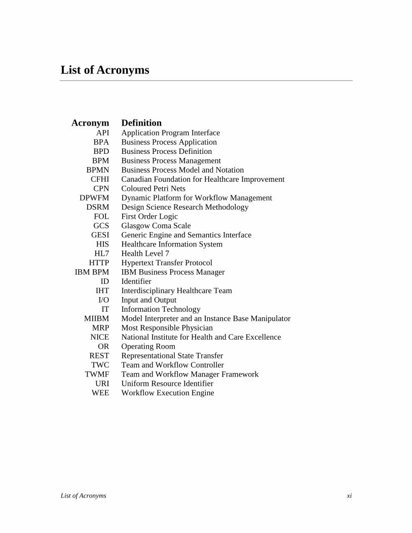
List of Acronyms xi
List of Acronyms
Acronym DefinitionAPI Application Program Interface
BPA Business Process ApplicationBPD Business Process DefinitionBPM Business Process Management
BPMN Business Process Model and NotationCFHI Canadian Foundation for Healthcare ImprovementCPN Coloured Petri Nets
DPWFM Dynamic Platform for Workflow ManagementDSRM Design Science Research Methodology
FOL First Order LogicGCS Glasgow Coma Scale
GESI Generic Engine and Semantics InterfaceHIS Healthcare Information SystemHL7 Health Level 7
HTTP Hypertext Transfer ProtocolIBM BPM IBM Business Process Manager
ID IdentifierIHT Interdisciplinary Healthcare TeamI/O Input and OutputIT Information Technology
MIIBM Model Interpreter and an Instance Base ManipulatorMRP Most Responsible PhysicianNICE National Institute for Health and Care Excellence
OR Operating RoomREST Representational State TransferTWC Team and Workflow Controller
TWMF Team and Workflow Manager FrameworkURI Uniform Resource Identifier
WEE Workflow Execution Engine
Introduction 1
Chapter 1. Introduction
This thesis addresses the difficult problem of managing care delivered by Interdiscipli-
nary Healthcare Teams (IHTs), whose composition (i.e., practitioners from different dis-
ciplines) changes over time. The continuous selection of appropriate team leaders and
members, and their allocation to tasks in a patient’s clinical process, represent examples
of team dynamics, one of the important components of IHT-provided care. The context of
interest here is one where Business Process Management (BPM) suites are used to model
healthcare clinical processes and manage their execution. The problem is that such tools
need to be supplemented with additional functionalities to associate, dynamically, suita-
ble practitioners with the tasks being part of these clinical processes. Such functionalities
can be modelled in many ways, including as a semantic layer that defines concepts for
dynamic team management supporting the allocation of process tasks to available and
relevant practitioners part of a team treating a patient. This thesis contributes a middle-
ware layer, with a generic interface, between such semantic layer and typical BPM suites
so they can cooperate. This middleware enables the addition of dynamic IHT manage-
ment to existing BPM suites, hence adding value to tools already used in a healthcare
context. A secondary contribution is the demonstration that an existing ontology used in
the semantic layer to define the concepts and relationships needed for dynamic IHT man-
agement is minimal, that is, all of its concepts and relations are necessary for the required
team functionalities (usually absent from BMP suites) to work properly.
This chapter presents research motivation, questions and objectives of this thesis.
1.1. Concepts and Motivation
A workflow is composed of tasks and of resources (including people) needed by these
tasks. A workflow’s tasks are sequenced in a way to accomplish a given goal. Workflows
are used for performing sets of processes and interactions by a set of people or other re-
sources available to accomplish the participant’s shared goal (Cain and Haque, 2008).
Introduction 2
Workflows are widely used in different industries, from finances to telecommuni-
cations and manufacturing, and many types of workflow management systems are used in
these contexts (van der Aalst et al., 2003). These systems have features focusing on the
definition and execution of the workflows.
Generic BPM suites1, which are tools that include workflow execution engines,
have begun to take the place of specialized healthcare workflow management systems in
last few years (Reichert 2011). As these tools evolve, they begin to provide more collabo-
ration features between organizational roles from different perspectives (Ko, 2009). Some
of the collaborative features commonly seen in BPM suites include mobility, social col-
laboration with instant communication, an integrated working environment, and shared
design and development components. For instance, The Ottawa Hospital automated some
of their traditional workflows with IBM BPM (IBM, 2012) and also added support for
mobility and collaboration with its integrated platform (IBM, 2013).
The thesis builds on previous work conducted by the University of Ottawa’s Mo-
bile Emergency Triage (MET) group, where a semantic layer for IHT was defined. A
multi-agent system was developed by Wilk et al. (2016) addressing the dynamic alloca-
tions of IHT members during workflow executions with this semantic layer. However,
this previous work uses a research platform for workflow execution, without collabora-
tion support, which would make it difficult to be accepted and deployed in a hospital en-
vironment, especially if the latter is already equipped with a commercial BPM suite.
Research shows that teams improve the effectiveness of healthcare delivery. To
utilize the full potential of team-based care, institutions, organizations, governments, and
individuals must invest in the people and processes that lead to improved outcomes
(Rowland, 2014; Borril et al., 2000). IHTs, which are a typical example of the team con-
cept, enable a collaborated and coordinated service in the health system (Nolte and
Tremblay, 2005; Andreatta, 2010). For instance, in the chronic pain management area,
IHTs raise the effectiveness of the treatment for the patient (Gatchel et al., 2014). The
importance of supporting IHTs is echoed by Canadian policy documents:
1 For a sample list of BPM suites, see http://bpm.com/vendor-guide

Introduction 3
“Legal and regulatory frameworks, as well as adequate financing and
funding, are necessary to support the shift to interdisciplinary collab-
oration.” (EICP, 2005)
In 2014, a not-for-profit organisation called the Canadian Foundation for Healthcare
Improvement (CFHI) published a document emphasizing the need of collaborative care
models involving interdisciplinary teams:
“Although inter-professional teams are proliferating particularly in
response to a growing need for care of patients living with multiple
chronic diseases, roles remain unclear and teams often tend to be
‘physician-centric’ rather than patient- and family-centric.” (Verna et
al., 2014, p. 11)
“Chronic care requires a team approach but progress [is] not keeping
pace with need.” (Verna et al., 2014, p. 11)
Commercial off-the-shelf BPM suites do not necessarily have the functionalities needed
to describe and reason about team dynamics, especially in an healthcare context. Re-
quired additional functionalities can be modeled outside of the engine, for example, in a
semantic layer that defines ontology for team dynamics. In such context, the main issue
becomes how to connect the semantic layer to the BPM suite such that they can interop-
erate to support dynamic team management during workflow execution. An intermediate
middleware, with a well-defined interface, is a potential way to integrate a semantic layer
with a BPM suite to execute IHT workflows in order to capture complex healthcare pro-
cesses while achieving dynamic team collaboration.
Introduction 4
1.2. Thesis Objective and Research Questions
The main problem addressed in this thesis is how to manage team dynamics during the
execution of healthcare workflows. We are particularly interested in a context where hos-
pitals are already taking advantage of BPM engines for supporting some aspects of clini-
cal workflows. Furthermore, as reusing existing BPM capabilities is of high value from a
financial perspective, this thesis focuses on a specific design approach (middleware inter-
facing between a BPM suite and a semantic layer) that aims to enrich workflow execution
engines with missing team behaviour components. In this context, this thesis investigates
the following research questions:
RQ1: What would a middleware between a semantic layer modeling team dynamics and
a feature-rich BPM engine be composed of?
RQ2: What would a minimal ontology for capturing IHT concepts contain in order to be
independent from underlying workflow engines?
To answer these questions, the thesis presents a system integrating (via a middleware
layer) an ontology-based semantic layer that captures team dynamics and a BPM suite as
an execution engine for healthcare workflows. Realistic scenarios are used as a proof of
concept covering the dynamics of IHTs.
1.3. Thesis Contributions
This research extends previous work done by Wilk et al. (2016) by reusing one of its el-
ement (semantic layer supporting IHT dynamics) and connecting it to a commercial BPM
engine. The main contribution of this thesis is:
The definition of a middleware layer with an interface (called Generic Engine and
Semantics Interface – GESI) that connects a team dynamics semantic layer to
BPM engines.
Minor contributions include:

Introduction 5
Demonstration that the semantic layer’s ontology is aligned it with the needs of
the system, including its middleware;
Proof-of-concept implementation of the middleware (with Representational State
Transfer and Java), connecting a specific implementation of team behaviour (se-
mantic layer) to a commercial BPM engine (IBM BPM software);
Proof-of-concept illustration of the feasibility and effectiveness of the middle-
ware-based approach through the use of two scenarios describing realistic clinical
processes: radical prostatectomy surgery (The Ottawa Hospital, 2010) and acute
stroke management (NICE, 2008).
1.4. Thesis Outline
The thesis chapters are as follows:
Chapter 2 presents the literature review done around the research questions. Im-
portant goals for the support of IHT dynamics are extracted from the literature
and used in an assessment of related work that compares existing studies and
highlights existing gaps.
Chapter 3 explains the steps of the Design Science Research Methodology
(DSRM) used to answer the research questions through two types of artifacts:
concepts and an implementation. The chapter also introduces the framework pro-
posed for research and the system architecture. Assumptions and system require-
ments that were iteratively produced from research goals are also presented.
Chapter 4 introduces a minor thesis contribution, answering RQ2 with an analysis
of the minimality of the IHT Ontology against the relevant goals identified
in Chapter 2. The ontology’s concepts and their relations are also described to en-
able better understanding of the overall approach.
Chapter 5 presents the major thesis contribution, answering RQ1. This core chap-
ter starts by providing information about the execution layer (IBM BPM), the se-
mantic layer, and the interface (GESI). It then presents the implementation of
GESI with IBM BPM in the middleware layer, including the mapping between
the interfaces and an overview of the translation logic. The development of the
Introduction 6
proof-of-concept implementation addressing our research question RQ1 is de-
scribed and detailed in that chapter.
Chapter 6 illustrates the feasibility and effectiveness of the middleware-supported
approach through its application and evaluation on two realistic IHT-oriented sce-
narios.
Chapter 7 compares the thesis work with closely related work in view of the goals
identified earlier. In addition, this chapter highlights a list of commercial and
open-source BPM suites (other than IBM BPM) that can satisfy the needs of the
middleware’s interface, hence demonstrating that the approach is not tied to IBM
BPM. Threats to validity are also discussed at the end of the chapter.
Chapter 8 summarizes the overall thesis with answers to the research questions
and highlights future work items.
Literature Review 7
Chapter 2. Literature Review
This chapter gives an overview of the literature related to the concepts and previous work
relevant to our research questions. After the presentation of the goals used to evaluate the
relevance of related work and a brief introduction to the methodology used for this litera-
ture review, different sections discuss the work on business process management (BPM),
interdisciplinary healthcare teams, and BPM implementations. A brief assessment of re-
lated work is also included.
2.1. Evaluation Goals
Different criteria can help us evaluate the relevance of related work and existing technol-
ogies in order to help answer the two research questions outlined in section 1.2. The goals
presented in this section were obtained iteratively while exploring the literature. The lit-
erature review has three main categories of concepts: BPM and BPM suites (section 2.3),
IHTs (section 2.4), and BPM suite implementation and products (section 2.5). Several
meetings with the thesis author’s supervisors involved discussions and suggestions until
the nine goal definitions presented here were obtained. In order to trace the goals to their
sources, they have been linked to papers in the next sections of the literature review.
Since one objective of the thesis is to manage different types of team dynamics
during workflow execution with a BPM suite, we are first interested in adding support for
team dynamics to workflow/BPM execution engines (WEE). Having a good work-
flow/process definition language to start with is essential for modeling and executing
healthcare processes. A good language is one that has a high popularity (Goal 1) in order
to increase the chances of adoption, and that has a high expressiveness level (Goal 2) to
handle different categories of clinical processes. Existing comparisons of workflow lan-
guages by Pourshahid et al. (2009; 2014) describe how to assess language features for
business process modeling, whereas Afrasiabi et al. (2009) further explore the criteria
targeting the healthcare sector in particular.
Literature Review 8
Requirements from a semantic layer perspective have three goals. First, the ontol-
ogy has to be able to support team dynamics (Goal 3), for instance, with role variability
and user preferences (especially in a patient-centric context). Teams in healthcare include
two or more members, who often have different roles and who manage the patient. Se-
lecting the most appropriate members is based on their availability and capabilities. Au-
tomatic capability-based assignments of tasks (Goal 4) should be handled in such con-
text. Finally, teams in healthcare, which are composed of interdisciplinary practitioners,
have a common goal to support patient management. A leader, who is also a member of
the team, has the highest responsibility of managing the patient (Taplin et al., 2013).
Members of the teams are responsible for the tasks they are assigned to do whereas a
leader is associated with the whole process that includes related tasks. A leader may also
be associated with a specific task. In such a membership context, both task-level and pro-
cess-level assignments (Goal 5) are needed. Since the focus of this thesis is in healthcare,
the ontology covering the team dynamics should have support for relevant healthcare
concepts (Goal 6). In healthcare, team leaders are identified for a given patient for their
management. Leaders of the teams are usually the most experienced members within the
teams they belong to, but they may have to be released from the team. Urgent tasks re-
quired elsewhere or having a conditional sub-process that needs a new leader are exam-
ples for the need for supporting frequently changing leaders (Goal 7). In addition, as
healthcare teams care for patients who have a wide diversity of issues not always fore-
seen by clinical processes, the handling of process exceptions (Goal 8) is another need.
Finally, there is a need to go beyond workflow execution to integrate user inter-
faces and collaborative work support (Goal 9), which is usually a benefit brought by
BPM suites over simple workflow execution engines.
We defined a collection of nine goals, with different granularities, that contribute
to the sound and practical support of IHT dynamics by BPM environments. Goal 6 on
ontologies targets specifically research question RQ2 in section 1.2, whereas the entire
set of nine goals relate to RQ1. The queries prepared to answer the research questions are
discussed in the next sections.

Literature Review 9
2.2. Literature Review Methodology
A literature review requires existing research to be surveyed, in order to understand what
exists and what is missing (the gap). Hence, multiple sources of information have been
queried. The literature review methodology for this thesis is inspired by Kitchenham’s
systematic reviews (Kitchenham, 2004) but does not constitute a systematic review per
se. Existing BPM platforms and models for IHTs executing business workflows in
healthcare were searched with different combination of keywords. Several important
sources of papers were used as follows:
Online publication search engines were used to collect scientific papers about
healthcare teams, ontologies, and BPM: PubMed, Scopus, SpringerLink, and
IEEE Xplore.
“Enhancing Interdisciplinary Collaboration in Primary Health Care (EICP)” arti-
cles, the “Canadian Health Human Resources Library” and “The College of Fami-
ly Physicians of Canada” publication archive were searched to understand the
need for and importance of healthcare teams in Canada.
The results were processed in the following order:
1. The initial search results were filtered with additional query criteria until a mini-
mum number of relevant papers were returned (at least 10 per search engine)
while remaining manageable (i.e., at most 40 per search engine; in general, re-
maining papers are far less relevant).
2. The results pointing to irrelevant topics (titles and keywords) were not included.
In the end, 114 peer-reviewed and grey literature publications were collected.
3. The resulting publications were studied through their abstracts to further filter out
irrelevant publications. After this step, 58 related publications were left.
4. Conclusion and related work sections were then studied to filter out weakly rele-
vant papers. At this step, 22 papers were left and they are to discuss in
tions 2.3 to 2.5.
5. The six most relevant papers for the thesis research are also assessed in Table 1
with respect to the nine goals. This enables us to find gaps in the current literature

Literature Review 10
while offering a basis for comparison with the approach developed later in the
thesis.
The results obtained through the above methodology are grouped in three concept catego-
ries: Business Process Management (BPM), Interdisciplinary Healthcare Teams (IHTs),
and BPM Implementations. Results related to BPM, BPM evolution, BPM usage areas,
and BPM in healthcare are explained in section 2.3. IHT, IHT needs in healthcare and
team-related BPM studies are reviewed in section 2.4. Several key BPM-related imple-
mentations are then presented in section 2.5.
2.3. Business Process Management (BPM) and BPM Suite
Basic concepts and terminology related to business process management (BPM), includ-
ing workflows, workflow management systems, business process modelling languages,
and BPM suites, together with some historical perspective, need to be introduced in this
section in order to better understand i) what is currently missing in the context of the
management of healthcare processes involving teams, and ii) the technical contributions
of this thesis. Business Process Management has many definitions, but this thesis uses
this one:
“A management discipline focused on using business processes as asignificant contributor to achieving an organization’s objectivesthrough the improvement, ongoing performance management, and gov-ernance of essential business processes.” (Jeston and Nelis, 2014)
Whereas a BPM is an activity, a practice to improve processes, a BPM engine is a tool:
“A generic software system that is driven by explicit process designs toenact and manage operational business processes.” (Van der Aalst etal., 2003)
BPM is used in industries as a general solution to improve organizations’ performance
while reducing their costs. Automation of these processes is achieved using software
products to minimize efforts. An off-the-shelf generic BPM suite, which provides tool

Literature Review 11
support for BPM, includes an integrated environment design for the execution, reporting,
and analysis of business processes, allowing business users to be involved (Hoogland,
2009).
The evolution of BPM suites has been from office automation systems to workflow man-
agement systems, which are the common solutions found in recent years (Schael, 1998;
Zur Muehlen, 2004). A workflow management system is mainly represented as business
process automation software with the focus on task assignment, to go to the next step and
enable the flow of entities (e.g., documents) attached to these tasks. Workflow manage-
ment systems are used in many industries, from manufacturing to healthcare, to automate
their processes (Dwivedi et al., 2001; Lenz et al., 2012; Hull et al., 2006). BPM is a field
of management focused on improving business processes in organizations that are most
closely related to the concept of the workflow management (Russel et al., 2006). Work-
flow management systems address the workflow pattern and task parts of any given pro-
cess solution (Lillehagen and Krogstie, 2008). Additionally, a BPM suite (a suite of busi-
ness process tools) includes a workflow management system and supports more function-
alities with an integrated platform (Jeston and Nelis, 2014). A generic BPM suite differs
from a workflow management system in several ways:
A BPM suite supports the whole BPM lifecycle: definitions of the processes and
the activities, modelling, execution, monitoring, and optimizing (Tchemeube,
2013; Vom Brocke and Rosemann, 2010; Emanuele and Koetter, 2007).
A BPM suite not only automates the processes and the physical movement of the
documents, but it also enables improving these processes (Dwivedi et al, 2001,
Malik, 2009).
A BPM suite includes analysis and simulation features for post-execution and pre-
execution of the process models. Optimizations and improvements are achieved
with the verification of these executions (Panagacos, 2012; Gilbert 2005).
A BPM suite focuses on continuous adaptation of overall processes (Lenz and
Kuhn, 2004). Workflow management systems mainly focus on execution of the
processes (Lillehagen and Krogstie, 2008; Lenz et al., 2012).
A BPM suite decreases the amount of interfaces needed between subsystems in
organisations (Jeston and Nelis, 2014; Panagacos, 2012).

Literature Review 12
A BPM suite not only supports a coordination environment, but also enables col-
laboration between groups, during the development or execution of the processes,
inside s discipline or across disciplines (Mendling et al., 2012).
Different types of business process languages, used for modelling business processes in
BPM suites, were found while doing the literature review. The languages that are model-
ling business process execution at run-time (e.g., BPEL, the Business Process Execution
Language (OASIS 2007)) are not found to be related to the thesis questions since clinical
processes are modelled at a higher level of abstraction, with languages such as (Coloured)
Petri Nets and the Business Process Model and Notation (BPMN).
Petri Nets were applied to workflow management two decades ago (van der Aalst,
1998). Coloured Petri Nets (CPN) tools are extensions of Petri Nets allowing editing,
simulating, and analyzing business processes while supporting the differentiation of task
instances (Westergaard and Slaats, 2013). The Access/CPN tool used to model and simu-
late CPN processes (Westergaard, 2011) has severe limitations because it does not in-
clude a workflow management system (Elmroth et al., 2008).
Most BPM suites chose popular and expressive languages (BPMN in particular)
to increase the level of interoperability with other systems (Pourshahid et al., 2009;
Pourshahid, 2014). BPMN, which is an Object Management Group standard (OMG,
2011), is also commonly used among these suites to represent business processes graph-
ically. Using a BPM suite that use BPMN satisfies Goal 1 and Goal 2. However, BPM
suites have challenges in healthcare since healthcare is a complex and risky domain (Ma-
thisen and Krogstie, 2012) because:
Treatments (clinical processes) of the patients depend on their context. Errors may
even result in patient death according to the Committee on Quality of Health Care
in America (Kohn et al., 2000).
Healthcare delivery represents an uncertain and time-pressured working environ-
ment. It has a shift-based system (where practitioners get replaced after a certain
number of hours) that may cause interruptions in handovers (Mackey and Nancar-
row, 2005).

Literature Review 13
Medical care is mostly a cognitive task about planning and decision making. Ad-
vanced technologies should be used for automation of the works (Ye et al., 2008).
Clinical decisions are made under several resource constraints. Staff, medical
equipment and facility availability is important to reduce waiting times. Coordina-
tion is required for managing resources, and resource availability should be taken
into account for proper resource allocation (Mathisen and Krogstie, 2012).
Collaborative work should be performed on patients whose illnesses and respons-
es to medical treatments are unpredictable (Bertolini et al., 2011).
As a result, BPM suites are not necessarily ready for this level of complexity (Emanuelle
and Koetter, 2007).
Both BPM suites and Workflow Management Systems involve an execution en-
gine to enable support for automated execution and management of processes. However,
complex healthcare workflows need to have a manageable and automated business pro-
cess while capturing different aspects of team dynamics.
2.4. Interdisciplinary Healthcare Teams (IHTs)
An Interdisciplinary Healthcare Team is a healthcare entity where a team includes mem-
bers, from many clinical disciplines and professions, who work together to provide opti-
mal, coordinated care for patient management (Oandasan et al., 2004; Butt and Caplan,
2010; Gordon, 2014). Both patients and healthcare professionals benefit from interdisci-
plinary collaborations with such a team composition (Watson and Wong, 2005).
Hall and Weaver (2001) state that the management of the complex healthcare do-
main (as explained in Section 2.3) requires specialized professionals to come together in
order to achieve the shared goal of better patient care. IHTs are especially needed in the
healthcare domain to follow patients in a continuous way (e.g., as for chronic diseases) or
to treat an increasing aging population with complex care needs. Nancarrow et al. (2013)
defined an effective IHT as having many characteristics, including:
Having a clear leader for the team.
Having a clear vision.

Literature Review 14
Sharing power and working jointly.
Having appropriate systems to improve communication in the team.
Knowing strengths and weaknesses, i.e., levels of capabilities for making proper
decisions.
Having, collectively, sufficient/appropriate capabilities.
Patients have better care delivered by having an effective IHT and a collaboration envi-
ronment (Hall and Weaver, 2001). Many problems occur related to the lack of sufficient
collaborative work of healthcare teams towards common goals such as incomplete speci-
fication of responsibilities, lack of continuity in teams working in shifts, lack of infor-
mation about practitioners’ capabilities, and lack of clarity about work assigned (Grando
et al., 2010; Grando et al., 2011) (Goal 9).
Capability-based assignments can be achieved with an ontology combined with
BPM (Hepp and Roman, 2007). An ontology for supporting teams is useful since team
members’ capabilities and responsibilities need to be clear in order to optimize the team’s
efficiency (Rowland, 2014) (Goal 4). Papapanagiotou et al. (2012; 2014) proposed a
framework to support collaborative work of healthcare teams. Their framework supports
assigning tasks to the most appropriate healthcare team members based on their capabili-
ties (Goal 4, Goal 6). However, their framework was not tested on workflows.
Schmidt and Kunzmann (2006) developed a human resource framework to com-
bine competence management and knowledge management (Goal 4). Activities are inte-
grated into work processes that are compiled from a goal-oriented model. Matching com-
petencies (with levels) to fit the requirements for applicant selection or for team staffing
is performed. The ontology provides links to the business processes that are connected to
a competency; however, their framework does not support team dynamics (Goal 3) and
process-level assignments (Goal 5).
There exist three types of approaches in the execution of IHT workflows: static,
hybrid, and dynamic. Static IHT means that practitioners are assigned to specific tasks of
a workflow and are not released until the workflow ends. A static team approach is not
useful for the efficient use of resource and it increases costs for team management. In a
hybrid approach, a practitioner gets involved in a team when needed, executes the next

Literature Review 15
task for which he/she possesses the related capability requirements, and leaves the team
when his/her capabilities are no longer required (Astaraky et al., 2013).
Changing team membership and leadership, as well as management and allocation
of workflow tasks to team members are important aspects of team dynamics in the care
provided by IHTs. The IHT dynamics approach is very similar to hybrid one with the
difference that the system also checks the practitioner’s availability since assignments are
task-based instead of workflow-based. This approach builds a set of behavioral rules de-
scribing the team dynamics that have the most potential to minimize possible execution
delays (Kuziemsky et al., 2014; Isern et al., 2011).
There have been several studies about the workflow management automation of
IHT. Prinyapol et al. (2009; 2010) developed a Dynamic Platform for Workflow Man-
agement (DPWFM) to support Goal 4 and Goal 6. The platform is used for the nursing
workflow management and allows role variability for a healthcare team, including a lead-
er (medical nurses and a supervisor/leader nurse) to manage requirement workflows dy-
namically (Goal 3). However, the assignment of the tasks is done manually (requires ad-
ditional work for the leader), which is not an efficient solution for coordinating teams in
healthcare.
Cabanillas et al. (2015) proposed a team composition and allocation approach
based on team member capabilities (Goal 4). The allocations are done at runtime (Goal 3)
and concepts have support for healthcare (Goal 6). BPMN language is used for modelling
(Goal 1, Goal 2). The allocation of team members leverages the concepts of role and or-
ganization hierarchy, especially for delegations and reporting issues. The focus on team
composition approach is on the activity level and it does not have an implementation
based on a BPM engine (Goal 9).
Kuziemsky et al. (2014) and Wilk et al. (2016) developed a framework to support
IHT dynamics (Goals 3 and 6). This framework includes an ontology that integrates
workflow, patient, and IHT concepts and relations, in a semantic layer. The assignment
of tasks to related members is achieved via an implementation based on Multi-Agent Sys-
tems (MAS). Practitioners who are members of the team execute tasks assigned to them
based on their capabilities, competencies, and availability. Capabilities are represented as
facts (e.g., draw_blood_sample or conduct_invasive_therapy) that are associated with

Literature Review 16
practitioners, and each practitioner can have multiple capabilities. Competency is a nu-
merical value indicating the competency of the practitioner (e.g., 1 for novice, 2 for regu-
lar, 3 for expert) and is used to assess potential members of the team. The availability of
practitioners (available, busy, or unavailable) is also monitored and taken into considera-
tion in the assignment procedure. These aspects show how to cope with team dynamics
(Goal 3) and with capability-based assignments to the tasks (Goal 4). The developed sys-
tem, called MET4, supports the management of frequently changing leaders (Goal 7).
However, MET4 is not benefiting from a BPM suite’s integrated collaborative environ-
ment. In addition, MET4’s ontology contains many concepts already found and supported
in BPM suites, leading to duplication and the possible inconsistencies.
2.5. BPM Suite Implementations and Products
In healthcare, workflow management systems are mainly used as process automation
systems (Emanuele and Koetter, 2007; Bertolini et al., 2011). Dang et al. (2008) captured
commitments of the executing workflows with workflow implementation (based on Mi-
crosoft BizTalk), and monitored it. This feature can be configured after a BPM suite im-
plementation. The study supports healthcare workflows (Goal 6), but the team concept
does not exist (Goal 3).
As the needs in industries evolve with emerging technologies (Gang, 2008; Vom
Brocke and Rosemann, 2010), demands on BPM suites have increased (Hill and Kerre-
mans, 2007). However, these generic evolutions for the industry resulted in limitations
for adaptations of the products to specific contexts (McAdam et al., 2005). To cope with
these limitations, BPM suites need to be combined with an additional layer to satisfy the-
se requirements. Fortunately, today’s BPM suites allow us to increase their capabilities to
adapt to industrial environments up to some extent. For example, Prater et al. (2012) ex-
tended Oracle BPM suite with semantic technology for process refinement (Goal 9).
However, their study is about high-level BPM and their implementation does not aim to
improve team management in workflows.
It is interesting that developerWorks - a technical resource centre and profession-
al’s network from IBM - has also a study by Dermler et al (2014) about dynamic teams.

Literature Review 17
Their approach is based on a team concept that is pre-defined and dynamically allocated
to their associated process/tasks. Some filters are used in these allocations to obtain a set
of members who are capable of executing the process/tasks. Pre-defined teams are select-
ed at design time and the filtering mechanism selects from these sets of users who will
perform the tasks at run-time. The study focuses on a business industry having depart-
ments and teams representing their departments. However, the healthcare environment
needs more flexibility as a particular practitioner can be assigned to any process task if
he/she is capable of executing it. Instead of restricting practitioners by the department
they are working, selection based on skills and their levels should be used. Moreover,
frequently changing leaders should be considered and the practitioners should be able to
leave team and be included into another team when needed.
There are several business-oriented BPM suites being used for different purposes
(Vom Brocke and Rosemann, 2010). However, some industries (e.g., healthcare) have
needs that require additional features from these tools in order to adapt their processes
(Emanuele and Koetter, 2007). The abilities of a BPM suite are mainly focused on multi-
disciplinary processes (Dabaghkashani, 2011; Emanuele and Koetter, 2007) and the use
of BPM suites is limited in healthcare since there is still a gap between commercial soft-
ware abilities and domain industry needs (Reichert, 2011; van der Aalst, 2004; Lenz et
al., 2012). Still, since BPM suites allow us to extend their capabilities to enable their ad-
aptation to new environments, interdisciplinary healthcare teams can potentially benefit
from such tools.
2.6. Assessment of Related Work
Table 1 summarizes our assessment of existing work most closely related to our objec-
tives. Closely related approaches are those that satisfy a high number of our nine goals
while being supported by an implementation. We firmly believe that the presence of im-
plementations is minimally required to validate and assess the usefulness of proposed
conceptual frameworks.
Evaluation criteria are based on the goals defined in section 2.1. Goal satisfaction is
measured using a three-valued scale. “Y” is used for the goals that are clearly supported

Literature Review 18
by the corresponding study. “N” represents the case where the goal is not supported at all
or where the study focus is unrelated with that goal. Finally, “+/-” is used for partial goal
satisfaction where:
The goal is not fully satisfied by the study, or
Some support may exist, however, it is not fully demonstrated.
As highlighted in the table, none of the closely related conceptual frameworks presented
in the selected papers satisfy all nine goals. Goal 9 (integration with BPM suites) is par-
ticularly ignored, except for an approach proposed by Prater et al. (2012), which does not
satisfy many other goals. The approach by Wilk et al. (2016) scores the highest, but has
only partial support for exceptions (especially the ones targeting team members) and no
integration with a BPM suite.
Table 1 Related work assessed against goals for the support of IHT dynamics
1:Po
pula
rity
2:Ex
pres
sive
ness
3:Te
am D
ynam
ics
4:Ca
pabi
lity-
Base
d
5: T
ask/
Proc
ess
Assi
gnm
ents
6: H
ealth
care
Conc
epts
7: L
eade
rs
8: E
xcep
tions
9: C
olla
bora
tion
Cabanillas et al. (2015) Y Y Y Y Y Y N N NDeveloperWorks (2014) Y Y +/- +/- Y N +/- +/- YPapapanagiotou et al. (2012) N +/- +/- N +/- Y Y Y NPrater et al. (2012) Y Y N N N N N N YPrinyapol et al. (2009) (DPWFM) +/- +/- +/- +/- Y Y +/- N NSchmidt and Kunzmann (2006) +/- +/- Y Y Y Y Y N NWilk et al. (2016) (MET4) Y Y Y Y Y Y Y +/- N
Overall, the literature review shows that BPM suites are not directly applicable for use in
an interdisciplinary healthcare team context. Having a well-known and expressive lan-
guage for business process models is important to reduce adaptation problems. Commer-
cial off-the-shelf BPM suites are good in terms of business process language popularity
and usually have good expressiveness but they are not flexible enough to cope with com-
plex healthcare workflows involving team dynamics. Extending BPM suites to manage
Literature Review 19
team dynamics (e.g., by modifying existing BPM suites, or by relying on external mech-
anisms such as semantic layers) remains an issue, and this gap is a need to be filled for
the healthcare industry. One way to fill this gap is to have a middleware layer interfacing
between a semantic layer (handling the concepts related to interdisciplinary healthcare
team dynamics) and a BPM suite (handling conventional business process and workflow
concepts).
2.7. Chapter Summary
This chapter provided a literature review of concepts and approaches related to the re-
search questions, together with a brief evaluation of existing approaches against nine im-
portant goals for the proper support of IHTs. The chapter first presented BPM systems
and their current role in industry, with a particular focus on BPM usage in healthcare.
Team composition in healthcare, dynamic allocation of resources, and BPM implementa-
tions were then discussed. Finally, an assessment of related work is given in Table 1,
which highlighted a gap in the satisfaction of our research goals, especially in terms of
support for leaders, exceptions, and collaboration.
The next section introduces the research methodology used to develop and assess
an artifact (i.e., software) that will better satisfy the nine goals (research question RQ1). It
also presents the architecture of the solution developed in this thesis.
Methodology and Architecture 20
Chapter 3. Methodology and Architecture
This chapter defines the research methodology used in the remaining chapters of this the-
sis, together with an overview of the abstract architecture (with the main components and
links) and the concrete architecture (exploiting specific technologies) explored to validate
our contributions. Assumptions about how well architectural components satisfy the
goals of IHT dynamics support are presented, and middleware/interface requirements are
also provided.
3.1. Methodology Definition
In order to conduct successful research, an appropriate methodology is needed. Since our
research problem implies the development and validation of an Information Technology
(IT) artefact (e.g., middleware concept and implementation) to solve the problem in itera-
tive steps, the Design Science Research Methodology (DSRM) from Hevner et al. (2004)
is appropriate and has been selected here.
First, the requirements for the integration of a semantic layer and an execution
layer have to be analyzed in detail. DSRM is appropriate as it enables us to fulfill the
requirements of a particular group of tasks and activities such as an interface definition,
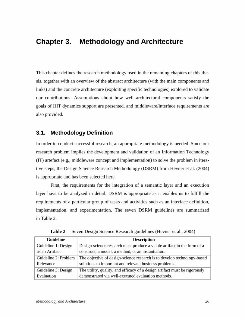
implementation, and experimentation. The seven DSRM guidelines are summarized
in Table 2.
Table 2 Seven Design Science Research guidelines (Hevner et al., 2004)
Guideline DescriptionGuideline 1: Designas an Artifact
Design-science research must produce a viable artifact in the form of aconstruct, a model, a method, or an instantiation.
Guideline 2: ProblemRelevance
The objective of design-science research is to develop technology-basedsolutions to important and relevant business problems.
Guideline 3: DesignEvaluation
The utility, quality, and efficacy of a design artifact must be rigorouslydemonstrated via well-executed evaluation methods.
Methodology and Architecture 21
Guideline DescriptionGuideline 4:ResearchContributions
Effective design-science research must provide clear and verifiable con-tributions in the areas of the design artifact, design foundations, and/ordesign methodologies.
Guideline 5:Research Rigor
Design-science research relies upon the application of rigorous methodsin both the construction and evaluation of the design artifact.
Guideline 6: Designas a Search Process
The search for an effective artifact requires utilizing available means toreach desired ends while satisfying laws in the problem environment.
Guideline 7:Communication ofResearch
Design-science research must be presented effectively both to technolo-gy-oriented as well as management-oriented audiences.
The following steps, which cover the guidelines, were used to answer research questions.
Although the mapping from the steps to the chapters appears to be sequential (due to the
linear nature of a thesis document), there were many micro-iterations (within steps) and
macro-iterations (across steps, often with validation meetings involving the author’s su-
pervisors between iterations):
1. Design as an artefact (Chapter 1: Introduction): There is a need for auto-
mating the dynamic allocation of the most capable available practitioners as
IHT members for a patient and for managing their workflows (with BPM
suites). This part identified the need for two design artefacts: conceptual con-
structs (a minimal IHT ontology and a generic interface for the middleware)
and an instance or implementation (the middleware implemented for a given
BPM suite).
2. Problem relevance (Chapter 2: Literature Review): This iterative step
helped obtain relevant goals from the literature and use these goals for evalu-
ating related work. The main problem is that workflow execution engines
supporting healthcare activities do not support IHTs well. One possible tech-
nology-based solution is the addition of a middleware layer interfacing be-
tween a semantic layer for IHT concepts and a workflow execution layer. The
semantic layer should be based on an ontology supplemented by rules and
functions supporting team dynamics. The execution layer should consist in an
existing workflow execution engine automating healthcare processes and ena-
Methodology and Architecture 22
bling healthcare professionals to benefit from its rich features. Such middle-
ware-based solution is a current gap in the healthcare industry.
3. Design evaluation (Chapter 3: Methodology and Architecture): DSRM is
used for design evaluation methodology. The design of the middleware arte-
fact (concepts and implementation) is done iteratively and is evaluated against
requirements and goals for supporting IHTs. The implementation actually
helped define the interface (as it emerged through refactoring and generaliza-
tion of the implementation code) and helped validate it.
4. Research contributions (Chapter 4: Ontology; Chapter 5: Middleware):
The contributions include the design of a middleware layer with an interface
definition (Generic Engine and Semantics Interface - GESI) integrating an on-
tology-based semantic layer (including a minimal ontology) with a BPM suite
in order to enable teams to participate dynamically to a workflow execution.
The two artefacts are hence the middleware (conceptual construct and in-
stance/implementation) and a minimal ontology (conceptual construct).
5. Research rigor and search process (Chapter 4: Ontology; Chapter 6:
Proof of Concept; Chapter 7: Evaluation): The implementation of the mid-
dleware with a proof-of-concept prototype is done according to software engi-
neering principles and exploits a commercial off-the-shelf workflow engine
(namely, IBM BPM). A descriptive method2 is chosen for the evaluation of
the artefact. The middleware is validated against requirements derived from
relevant goals for supporting IHT dynamics. The minimality of the ontology is
presented by arguing that the absence of any of its concepts or relations would
make at least one goal unsatisfied. Realistic proof-of-concept scenarios are
used to demonstrate the middleware’s implementability and utility. The ex-
pected threats to validity are evaluated based on the approach of Perry et
al. (2000).
2 Hevner et al. (2004) proposed five different methods for evaluating design science research. The descrip-tive method represents a combination of ‘Informed Argument’ and ‘Scenarios’ components. The InformedArgument component uses information from a knowledge base to build a convincing argument for theartifacts utility. The scenarios component constructs a detailed scenario around the artifact to demonstrateits utility.

Methodology and Architecture 23
6. Communication (Chapter 8: Conclusions): The results of the research are
planned to be shared through publications. Conclusions are presented as the
last chapter of the thesis document.
3.2. Architecture
The software architecture used in this thesis to support IHT dynamics in business pro-
cesses is based on the work of Kezadri et al. (2015), which is present also in Wilk et al.
(2016). This is a layered architecture composed of three layers (semantic, middleware,
and execution), illustrated at a high level of abstraction in Figure 1.
Semantic Layer Components
Workflow Execution Engine (WEE) Hospital InformationSystem (HIS)
Sem
antic
Laye
rEx
ecut
ion
Laye
r
Interface and Translation Logic
Figure 1 High-level software architecture for IHT dynamics implementation
A design and development of a Middleware Layer, which is the subject of this thesis,
enables the Semantic Layer and the Execution Layer to interoperate. The semantic layer
is composed of Semantic Layer Components, which includes an ontology, and enables the
dynamic allocation of (healthcare) teams to business (clinical) processes. The execution
layer is composed of two subsystems: a Workflow Execution Engine (WEE) (also called
Workflow Engine) and a Hospital Information System (HIS). The HIS is a system where
patient records are stored and where the registration of a patient is done by an admissions
clerk. Patient information is entered to that system, including the patient’s identification
information and all data related to the patient’s presentation (e.g., a specific disease or
condition).
WEE is the main component of a BPM suite. Typically, an Application Program-
ming Interface (API) or a messaging interface is provided by a BPM suite to enable ex-

Methodology and Architecture 24
ternal interactions with its workflow execution engine. Such capability enables an inter-
face composition that can connect the WEE with an external semantic layer. The main
contribution of this thesis is the definition and implementation of the middleware layer,
where the interface is located.
Whereas the high-level architecture in Figure 1 presents subsystems at a very
high level of abstraction, the abstract architecture (Figure 2) digs one level deeper into
this view, while maintaining independency from concrete implementation technologies.
A selection of specific technologies turns an abstract architecture into a concrete archi-
tecture (Figure 5).
Sem
antic
Laye
rEx
ecut
ion
Laye
rM
iddl
ewar
e Lay
er
Instance Base
Behavioral Rules
IHT Ontology Reasoner Solution
Semantic Components
Other BPM Suite Components
Workflow Execution Engine
BPM Suite
Data flow
Triggering
Legend
Model Interpreter and InstanceBase Manipulator (MIIBM)
Team and WorkflowController
GESI (Interface)
Hospital InformationSystem (HIS)
RQ1 and mainthesis contribution
Figure 2 Abstract architecture, with a closer look
The abstract architecture used in this thesis is influenced by the Team Management
Workflow Framework (TWMF) of Kezadri et al. (2015). In the previous architecture, the
semantic layer was interacting with the BPM engine directly. This structure was separat-
ed iteratively (one function at a time) to have a well-defined controller (Team and Work-

Methodology and Architecture 25
flow Controller – TWC) for the BPM engine, and a middleware layer was added in be-
tween to enable a generic and decoupled interoperation.
The Semantic layer is composed of Semantic Components, a Reasoner, the (pro-
duced) Solution defining team’s member task allocation, a Model Interpreter, an Instance
Base Manipulator (MIIBM), and a TWC. These components are defined below:
Semantic Components include the IHT Ontology, Behavioural Rules and an In-
stance Base. The IHT Ontology has concepts and relations defining IHTs and
their interactions with other elements such as practitioners, patients, and work-
flows. Instances of executions related to the ontology concepts are kept in an In-
stance Base whereas Behavioural Rules model the dynamic structure of the IHTs.
The Reasoner is a solution finder used to drive required parameters for assign-
ments of tasks/workflows to practitioners. The Reasoner interoperates with Se-
mantic Components for the practitioners’ assignments.
The Solution abstraction illustrates solutions returning from the Reasoner, i.e., as-
signments of tasks and processes to practitioners.
The Model Interpreter and Instance Base Manipulator (MIIBM) provides an in-
terface enabling one to run the Reasoner with specified data, get the generated
model from the Reasoner, and send the interpretation of the generated model. In
other words, the MIIBM selects the related information from the Instance Base
and builds the reasoning context.
The Team and Workflow Controller (TWC) sits between the MIIBM and the mid-
dleware. It sends/receives messages to/from the middleware via the interface
(GESI). It also interprets the content of the Solution to invoke GESI in order to
send commands to the WEE.
The Hospital Information System (HIS) and the BPM Suite are associated with the execu-
tion layer. A HIS notifies the middleware when a new patient is registered. A BPM Suite
is a combination of several components to manage business processes. In the Abstract
architecture, this software is composed of two pieces: the Workflow Execution Engine
(WEE) and other BPM Suite components (e.g., for collaborative work or for monitoring
and simulations).
Methodology and Architecture 26
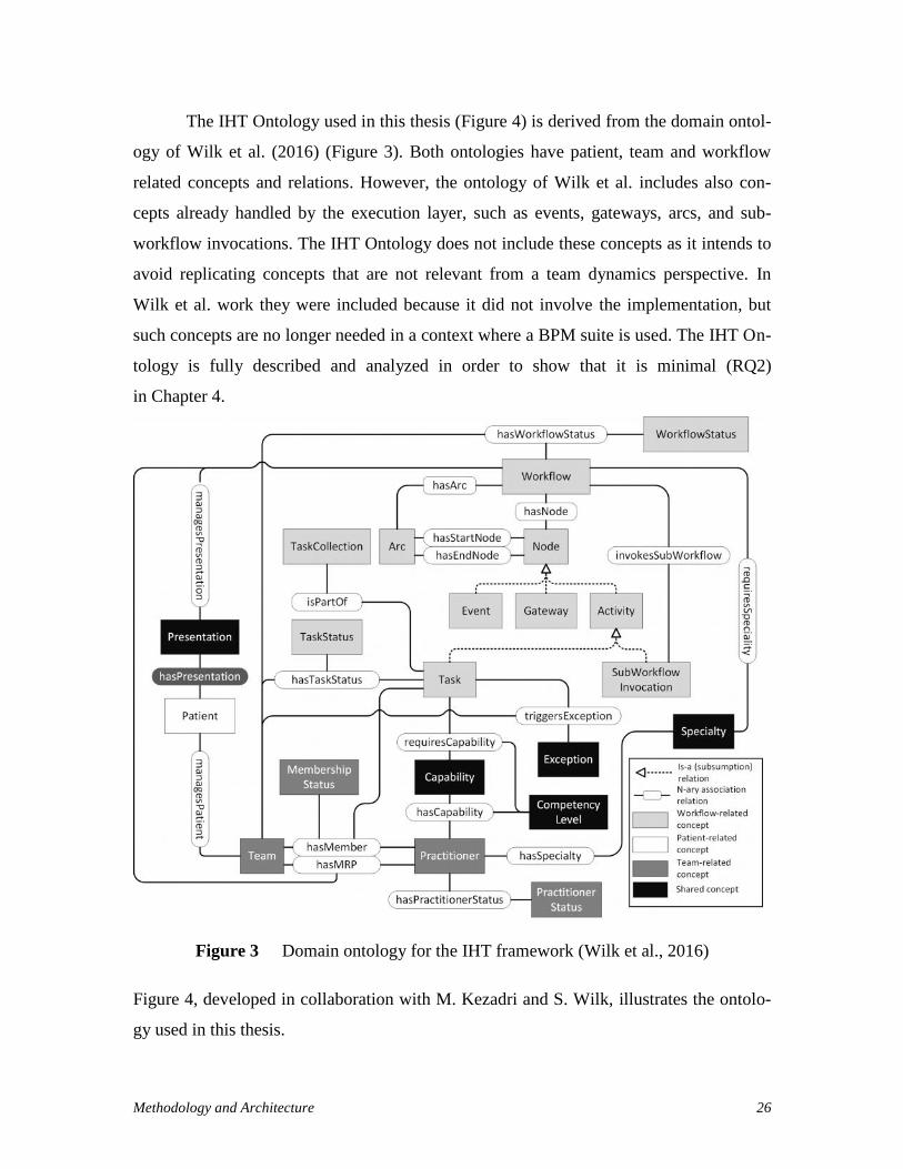
The IHT Ontology used in this thesis (Figure 4) is derived from the domain ontol-
ogy of Wilk et al. (2016) (Figure 3). Both ontologies have patient, team and workflow
related concepts and relations. However, the ontology of Wilk et al. includes also con-
cepts already handled by the execution layer, such as events, gateways, arcs, and sub-
workflow invocations. The IHT Ontology does not include these concepts as it intends to
avoid replicating concepts that are not relevant from a team dynamics perspective. In
Wilk et al. work they were included because it did not involve the implementation, but
such concepts are no longer needed in a context where a BPM suite is used. The IHT On-
tology is fully described and analyzed in order to show that it is minimal (RQ2)
in Chapter 4.
Figure 3 Domain ontology for the IHT framework (Wilk et al., 2016)
Figure 4, developed in collaboration with M. Kezadri and S. Wilk, illustrates the ontolo-
gy used in this thesis.

Methodology and Architecture 27
Workflow
TaskInstance
TaskCollectionTaskInstanceStatus isPartOf
hasTaskInstanceStatus
WorkflowInstanceStatus
Team Practitioner Specialty
Capabilityha
sCap
abili
ty
hasSpecialty
requiresCapability
requiresSpeciality
hasSuggestedMember
Patient
managesPatient
Presentation
hasPresentation
managesPresentation
CapabilityLevel
Concepts: Association relations:
PractitionerStatus
hasPractitionerStatus
hasWorkflowStatus
SpecialtyLevel
hasPriority TaskPriority
shouldChangeAssignment
Task
WorkflowInstance
isComposedOf
triggersException
isInstanceOfWorkflow
isInstanceOfTask
hasCollectionMember
hasAssignedMember
selectedWorkflow
executesWorkflowInstance
Team-related
Patient-related
Workflow-related
Shared
Team-related
Patient-related
Workflow-related
hasMRP
isElig
ible
ForT
ask
isElig
ible
ForT
askC
olle
ctio
n
Exception
Figure 4 IHT Ontology used in this thesis
Figure 5 is the Concrete architecture, including existing work presented in Figure 4 with
a selection of specific technologies for the relevant components and links from the ab-
stract architecture:
The Z3 Prover from Microsoft Research (2015) was selected as the Reasoner. Z3
is a powerful First Order Logic (FOL) theorem prover and model finder. FOL us-
es quantified variables over (non-logical) objects. A FOL theorem prover enables
automated theorem proving (also called automated reasoning). Z3 provides an
API library for clients that can be used with many software languages. The
MIIBM takes the advantage of Z3’s C++ API libraries and manipulates models
defined with the behavioural rules.
The TWC is implemented in Java so it can interact with GESI.
Methodology and Architecture 28
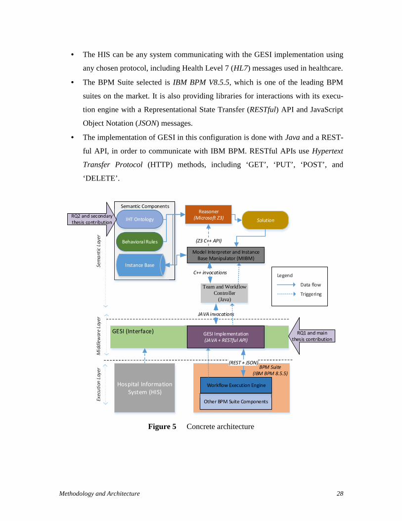
The HIS can be any system communicating with the GESI implementation using
any chosen protocol, including Health Level 7 (HL7) messages used in healthcare.
The BPM Suite selected is IBM BPM V8.5.5, which is one of the leading BPM
suites on the market. It is also providing libraries for interactions with its execu-
tion engine with a Representational State Transfer (RESTful) API and JavaScript
Object Notation (JSON) messages.
The implementation of GESI in this configuration is done with Java and a REST-
ful API, in order to communicate with IBM BPM. RESTful APIs use Hypertext
Transfer Protocol (HTTP) methods, including ‘GET’, ‘PUT’, ‘POST’, and
‘DELETE’.
Sem
antic
Laye
rEx
ecut
ion
Laye
rM
iddl
ewar
e Lay
er
Instance Base
Behavioral Rules
IHT OntologyReasoner
(Microsoft Z3) Solution
Semantic Components
Other BPM Suite Components
Workflow Execution Engine
BPM Suite(IBM BPM 8.5.5)
JAVA invocations
(Z3 C++ API)
Data flow
Triggering
Legend
(REST + JSON)
Model Interpreter and InstanceBase Manipulator (MIIBM)
C++ invocations
Team and WorkflowController
(Java)
GESI (Interface)
Hospital InformationSystem (HIS)
RQ1 and mainthesis contribution
GESI Implementation(JAVA + RESTful API)
Figure 5 Concrete architecture
Methodology and Architecture 29
As a result, this set of the technologies used to implement the abstract architecture, will
help support interdisciplinary healthcare team dynamics as an required functionality of
the selected BPM suite’s execution engine.
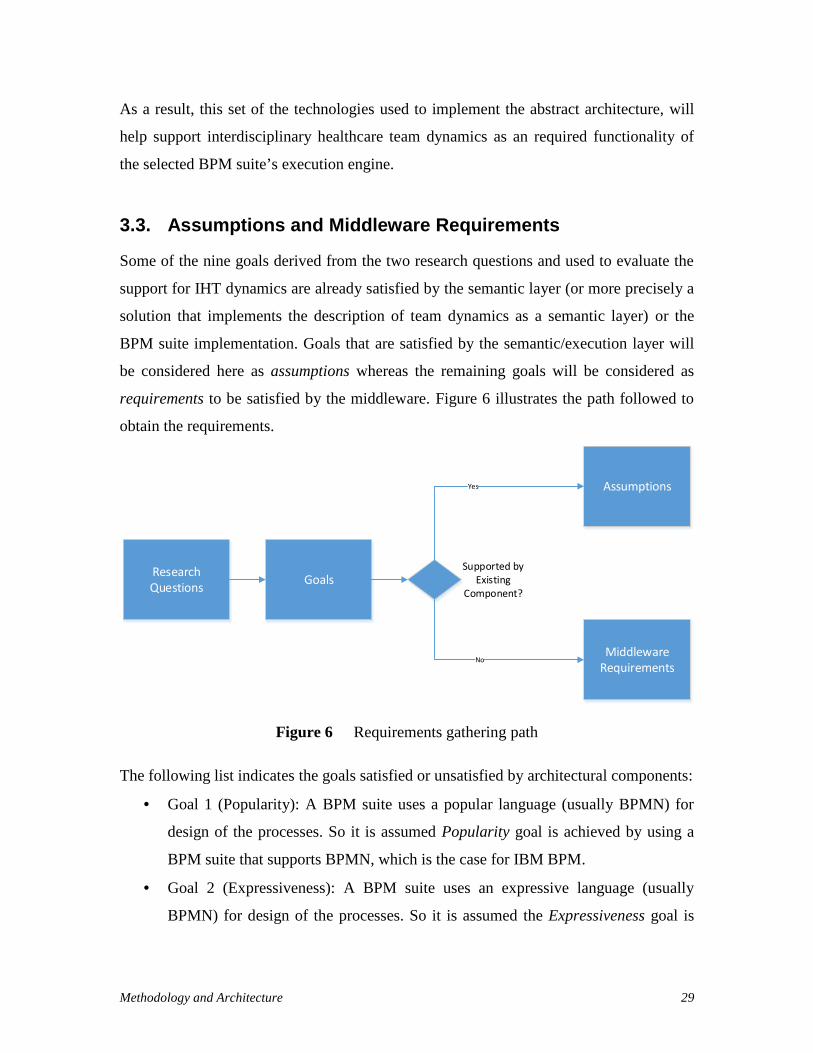
3.3. Assumptions and Middleware Requirements
Some of the nine goals derived from the two research questions and used to evaluate the
support for IHT dynamics are already satisfied by the semantic layer (or more precisely a
solution that implements the description of team dynamics as a semantic layer) or the
BPM suite implementation. Goals that are satisfied by the semantic/execution layer will
be considered here as assumptions whereas the remaining goals will be considered as
requirements to be satisfied by the middleware. Figure 6 illustrates the path followed to
obtain the requirements.
ResearchQuestions Goals
Assumptions
MiddlewareRequirements
Supported byExisting
Component?
Yes
No
Figure 6 Requirements gathering path
The following list indicates the goals satisfied or unsatisfied by architectural components:
Goal 1 (Popularity): A BPM suite uses a popular language (usually BPMN) for
design of the processes. So it is assumed Popularity goal is achieved by using a
BPM suite that supports BPMN, which is the case for IBM BPM.
Goal 2 (Expressiveness): A BPM suite uses an expressive language (usually
BPMN) for design of the processes. So it is assumed the Expressiveness goal is

Methodology and Architecture 30
achieved by implementing a BPM suite that supports BPMN, which is the case for
IBM BPM.
Goal 3 (Team Dynamics): The team dynamics goal is satisfied by the ontology
and other semantic components. It is assumed that the Team Dynamics goal is
achieved by interoperating with a semantic layer.
Goal 4 (Capability-Based): Capability-based assignments are partially supported
by the semantic layer. It is assumed that capabilities (based on their levels) are se-
lected in the semantic layer and matched with the task associated with a patient’s
workflow. Matching practitioner identifiers need to be assigned to users in the
BPM suite.
Goal 5 (Task/Process Assignments): Task/Process assignments are partially sup-
ported by the semantic layer. It is assumed that the tasks and processes are select-
ed in the semantic layer and matched with a patient’s workflow. Matched tasks
and processes identifiers need to be assigned to users in the BPM suite.
Goal 6 (Healthcare Concepts): Supporting Healthcare concepts goal is satisfied
by virtue of having a healthcare-oriented ontology. So, it is assumed that having a
semantic layer that includes such an ontology satisfies the support of healthcare
concepts.
Goal 7 (Leaders): Assignments of frequently changing leaders are partially sup-
ported by the semantic layer. It is assumed that the leader (practitioner) identifiers
are selected in the semantic layer and matched with a patient’s associated work-
flow process. Matched leader identifiers need to be assigned to users in the BPM
suite.
Goal 8 (Exceptions): Exceptions are mostly handled according to how they are
implemented in a BPM suite (Reichert et al., 2011; Sinur and Hill, 2010). Howev-
er, some BPM-level exceptions need to update information in the semantic layer.
So, it is assumed that having a BPM suite implementation partially supports ex-
ception handling.
Goal 9 (Collaboration): A BPM suite’ integrated platform enables the collabora-
tion of its users (practitioners) and supports collaborative processes including
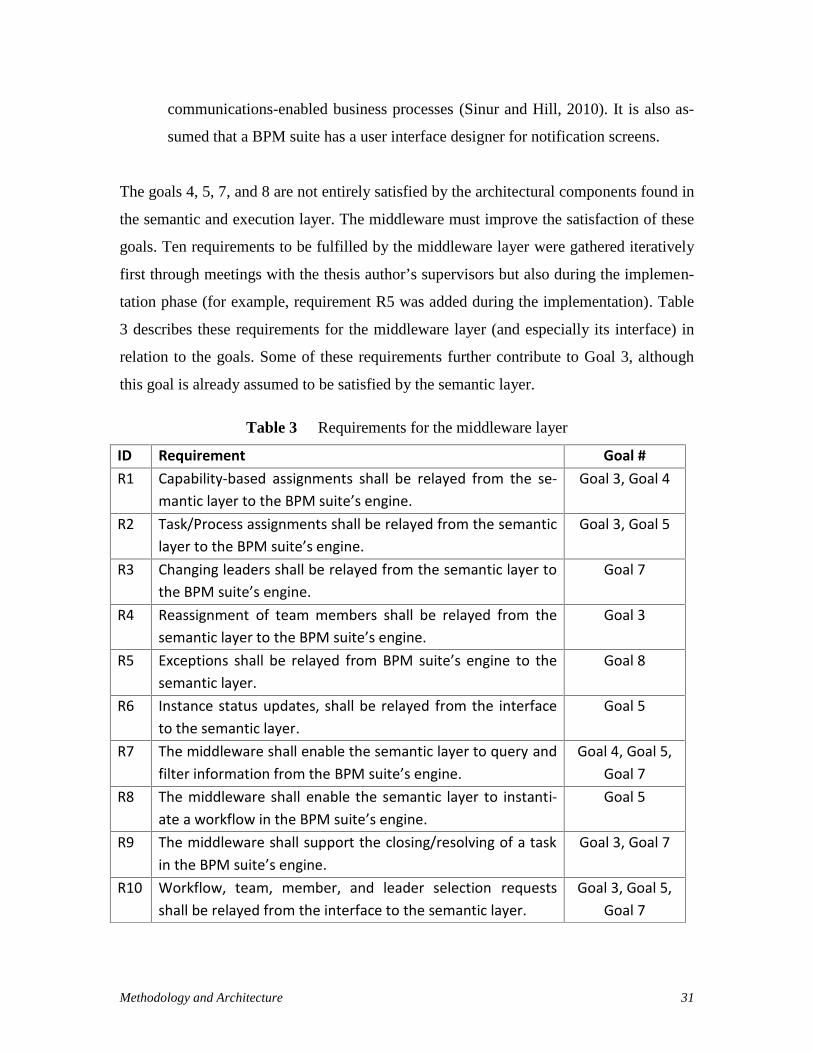
Methodology and Architecture 31
communications-enabled business processes (Sinur and Hill, 2010). It is also as-
sumed that a BPM suite has a user interface designer for notification screens.
The goals 4, 5, 7, and 8 are not entirely satisfied by the architectural components found in
the semantic and execution layer. The middleware must improve the satisfaction of these
goals. Ten requirements to be fulfilled by the middleware layer were gathered iteratively
first through meetings with the thesis author’s supervisors but also during the implemen-
tation phase (for example, requirement R5 was added during the implementation). Table
3 describes these requirements for the middleware layer (and especially its interface) in
relation to the goals. Some of these requirements further contribute to Goal 3, although
this goal is already assumed to be satisfied by the semantic layer.
Table 3 Requirements for the middleware layer
ID Requirement Goal #R1 Capability-based assignments shall be relayed from the se-
mantic layer to the BPM suite’s engine.Goal 3, Goal 4
R2 Task/Process assignments shall be relayed from the semanticlayer to the BPM suite’s engine.
Goal 3, Goal 5
R3 Changing leaders shall be relayed from the semantic layer tothe BPM suite’s engine.
Goal 7
R4 Reassignment of team members shall be relayed from thesemantic layer to the BPM suite’s engine.
Goal 3
R5 Exceptions shall be relayed from BPM suite’s engine to thesemantic layer.
Goal 8
R6 Instance status updates, shall be relayed from the interfaceto the semantic layer.
Goal 5
R7 The middleware shall enable the semantic layer to query andfilter information from the BPM suite’s engine.
Goal 4, Goal 5,Goal 7
R8 The middleware shall enable the semantic layer to instanti-ate a workflow in the BPM suite’s engine.
Goal 5
R9 The middleware shall support the closing/resolving of a taskin the BPM suite’s engine.
Goal 3, Goal 7
R10 Workflow, team, member, and leader selection requestsshall be relayed from the interface to the semantic layer.
Goal 3, Goal 5,Goal 7

Methodology and Architecture 32
Middleware requirements fill the gap (related to Goals 4, 5, 7, and 8) to satisfy the nine
identified goals. Goals that are already satisfied by the Team and Workflow Management
Framework (TWMF) component (Kezadri et al., 2015), as explained in the previous bul-
let list, are summarized in Table 4.
Table 4 Assumptions about goals based on existing components
Assumptions Goals ComponentsA1 Popularity (Goal 1) BPM suiteA2 Expressiveness (Goal 2) BPM suiteA3 Team dynamics (Goal 3) Semantic layerA4 Healthcare concepts (Goal 6) Semantic layerA5 Collaboration (Goal 9) BPM suite
3.4. Chapter Summary
This chapter justified the use of the Design Science Research Methodology and adapted
the latter to the context of the thesis. It also defined the abstract architecture of the thesis’
middleware, together with a concrete architecture where specific technologies were se-
lected in order to build a proof-of-concept prototype. From this architecture and from the
nine goals for supporting IHT dynamics defined in the previous chapter, a set of assump-
tions were made for the goals that are satisfied by existing components, and ten require-
ments were defined for the middleware so that the remaining goals get satisfied.
The next chapter focuses on an important component of the Semantic Layer,
namely the IHT Ontology briefly highlighted in this chapter, to discuss its concepts and
relations in more detail and to justify their existence in view of our nine goals, hence
providing an argument that this ontology is minimal (and answering research question
RQ2).
Then, Chapter 5, which is the core chapter of the thesis, will address RQ1 with the
design and implementation of the Middleware Layer, including its interface.

Minimal IHT Ontology 33
Chapter 4. Minimal IHT Ontology
The IHT Ontology, summarized in Figure 4, is a component defining the concepts and
their relations found in the semantic layer. Instances of these concepts and relations are
represented using First Order Logic (FOL) predicates and functions, and they are stored
in the instance base (Figure 5). The MIIBM updates the instance base by adding and re-
moving instances. The reasoner uses this information as input and, using behavioural
rules, produces solutions to the problem of assigning appropriate practitioners to tasks.
The Z3 theorem prover, which is the reasoner in our system, is invoked to build,
maintain, and release teams dynamically. For instance, there is a rule to assign a practi-
tioner to a task that he/she is capable of executing, and this rule uses the ontology’s Prac-
titioner and Capability concepts together with the hasCapability relation, as instantiated
in the instance base.
This chapter aims to demonstrate that the IHT Ontology in Figure 4 is minimal,
that is, all of its concepts and relations are necessary to satisfy the relevant goals identi-
fied for the support of IHT dynamics. In other words, removing any of these concepts or
relationship would result in some relevant goal to become unsatisfied.
In order to argue that this IHT Ontology is minimal, the concepts and their rela-
tions are analyzed individually. This chapter focuses on the analysis end results, but an
iterative process was applied in collaboration with the thesis supervisors, in order to in-
crease the trust in these results, especially regarding the necessary nature of some rela-
tions of the ontology.
According to the discussion in section 3.3, the goals relevant to the semantic layer
are: Team dynamics (Goal 3), Capability-based (Goal 4), Task/Process assignments
(Goal 5), Healthcare concepts (Goal 6), Leaders (Goal 7) and Exceptions (Goal 8). Goals
1, 2, and 9 are solely relevant to the BPM suite (see the assumptions in Table 4) and
hence do not impact the ontology.

Minimal IHT Ontology 34
The IHT Ontology contains three groups of concepts and relations: Team, Patient,
and Workflow (shown using different shades in Figure 4). Some of the concepts overlap
and are defined as a fourth group of Shared concepts. The next four sections discuss con-
cepts and relations for the shared, workflow, patient, and team groups. Some of the con-
cepts may have attributes (e.g., a name of type string) but these are not discussed for sim-
plification, without any impact on the argumentation presented in this chapter.
4.1. Shared Concepts
There are six concepts that span some of the groups. They are presented and analyzed
first because the concepts of the other groups depend on them.
Presentation: This concept defines the patient’s disease or medical problem. If
this core concept is removed, the Healthcare Concepts goal cannot be achieved (Goal 6).
Specialty: This concept defines a particular area of medical practice (e.g., cardi-
ology) used to qualify practitioner specialities and workflow requirements, and used to
select the leader of the team. If this concept is removed, the Leaders goal cannot be satis-
fied (Goal 7).
Specialty Level: This concept defines the level of expertise of a particular spe-
cialist, for example, Resident, Regular or Expert. If this concept is removed, the Leaders
goal cannot be satisfied (Goal 7).
Capability: This concept defines a fine-grained skill (e.g., taking the blood pres-
sure) used to qualify practitioners (in terms of what they can do) and tasks (in terms of
what is required). If this concept is removed, the Capability-based assignment goal can-
not be satisfied (Goal 4).
Capability Level: This concept defines the level of expertise associated with a
particular capability, for example, Resident, Regular or Expert. If this concept is re-
moved, the Capability-based assignment goal cannot be satisfied (Goal 4).
Exception: This concept defines an exceptional or unexpected problem with the
execution of a task in a clinical workflow. If this core concept is removed, the Exceptions
goal cannot be satisfied (Goal 8).
Minimal IHT Ontology 35
4.2. Workflow-Related Concepts and their Relations
The workflow sub-ontology consists of eight concepts and twelve associated relations.
4.2.1 Concepts
Workflow: The (clinical) workflow concept represents a process (composed of
tasks) to treat a patient. This core concept is needed to support the Team dynamics (Goal
3), Capability-based (Goal 4), Task/Process Assignments (Goal 5), Healthcare concepts
(Goal 6) and Leaders (Goal 7) goals.
WorkflowInstance: This is a particular instance of a workflow. If the concept is
removed, the identification of different (possibly concurrent) instances of the same clini-
cal workflow cannot be done. The concept is needed to support Task/Process Assign-
ments (Goal 5).
WorkflowInstanceStatus: This concept indicates the status of a workflow in-
stance. Possible statuses are: Running for a workflow instance being executed, MRPSe-
lection for an instance waiting for a leader to be selected, and Completed for an instance
that has been completed. The concept is needed to support the Leaders (Goal 7).
Task: A task is an activity, part of a workflow, which needs to be performed by a
practitioner. This concept is needed to support the Team dynamics (Goal 3), Capability-
based (Goal 4), Task/Process Assignments (Goal 5), and Leaders (Goal 7) goals.
TaskInstance: This is a particular instance of a task. If the concept is removed,
the identification of different (possibly concurrent) instances of the same task cannot be
done. The concept is needed to support Task/Process Assignments (Goal 5).
TaskInstanceStatus: This concept indicates the status of a task instance. Possible
statuses are: Waiting for a task instance that is waiting for execution, MemberSelection
for a task instance waiting for a practitioner to be assigned, Executing for a task instance
being executed, and Executed for a task instance that is completed. This concept is need-
ed for capturing status of the tasks to achieve Team dynamics (Goal 3), Capability-based
(Goal 4), and Task/Process Assignments (Goal 5).
TaskCollection: This concept is used to represent a group (collection) of tasks in
a workflow to be considered all at once for the selection of suitable practitioners (rather
than just looking at the next task). This is also used to capture the next tasks to perform

Minimal IHT Ontology 36
after a parallel gateway in a workflow definition. This concept is needed to support Team
dynamics (Goal 3), Task/Process Assignments (Goal 5), and Leaders (Goal 7) goals.
TaskPriority: The concept is defined to differentiate Normal tasks from Urgent
tasks. If this concept is removed, the handling of urgent tasks (which may require the
reassignment of a practitioner currently working on a normal task) cannot be done. This
concept is needed to satisfy Team Dynamics (Goal 3).
4.2.2 Relations
requiresSpeciality (Workflow, Specialty, SpecialtyLevel): This relation relates
the specialties and their levels required by a workflow. This relation is needed for sup-
porting the management of the Leaders (Goal 7).
isInstanceOfWorkflow (Workflow, WorkflowInstance): This relation relates a
workflow instance (reflecting the one created in BPM suite) to its workflow definition. If
the relation is removed, a leader cannot be selected for this instance as only from the
workflow definition it is possible to learn about required specialties. This relation is
needed for supporting the management of the Leaders (Goal 7).
hasWorkflowStatus (WorkflowInstance, WorkflowStatus): This relation de-
fines the status of a particular workflow instance and the associated team. This relation is
needed for supporting the management of the Leaders (Goal 7).
managesPresentation (Workflow, Presentation): This relation associates a
workflow to a particular presentation. As this relation captures essential medical
knowledge (linking symptoms to medical treatments), if it is removed, then Healthcare
concepts (Goal 6) cannot be satisfied.
executesWorkflowInstance (WorkflowInstance, Team): This relation relates
the team with a particular workflow instance. If this relation is removed, the team manag-
ing a patient cannot be captured through a workflow instance, and hence Team Dynamics
goal cannot be satisfied (Goal 3).
isComposedOf (Workflow, Task): This relation indicates which tasks belong to
a workflow. This relation is needed to reason about suggestions for future assignments of
tasks to practitioners. If the relation is removed, Team Dynamics (Goal 3) goal cannot be
satisfied.

Minimal IHT Ontology 37
isPartOf (Task, TaskCollection): This relation indicates which tasks belong to a
task collection. This relation is also needed to reason about suggestions for future as-
signments of tasks to practitioners (taking into consideration past history between a pa-
tient and practitioners). If the relation is removed, Team Dynamics (Goal 3) goal cannot
be satisfied.
isInstanceOfTask (Task, TaskInstance): This relation relates a task instance to
its task definition. The concept is needed to support Task/Process Assignments (Goal 5).
hasTaskInstanceStatus (Task, TaskStatus): This relation defines the status of a
particular task instance. This relation is needed for capturing statuses of the tasks to
achieve Team dynamics (Goal 3), Capability-based (Goal 4), and Task/Process Assign-
ments (Goal 5).
requiresCapability (Capability, Task, CapabilityLevel): This relation indicates
the capabilities (and their levels) required by a task. If this relation is removed, the Capa-
bility-based assignment goal cannot be satisfied (Goal 4).
hasPriority (Task, TaskPriority): This relation indicates the priority of a task. If
this relation is removed, then the Team Dynamics goal cannot be achieved (Goal 3).
triggersException (TaskInstance, Exception): This relation specifies an excep-
tion coming from a task instance, which is itself reflecting an exception triggered by the
corresponding task instance in the underlying BPM engine. If this relation is removed,
the Exception goal cannot be satisfied (Goal 8).
4.3. Patient-Related Concept and its Relations
The patient sub-ontology consists of one concept and two associated relations.
4.3.1 Concept
Patient: A patient is a person with health problems that need to be treated. This is
a concept required to satisfy Healthcare concepts (Goal 6).

Minimal IHT Ontology 38
4.3.2 Relations
hasPresentation (Patient, Presentation): This relation indicates that a patient
presents particular symptoms (i.e., health problems). If the relation is removed, the selec-
tion of the right workflow for this patient cannot be done, and hence Task/Process As-
signments (Goal 5) cannot be supported.
selectedWorkflow (Patient, Workflow): This relation indicates that a patient in
involved in a specific clinical workflow. If the relation is removed, the selection of the
right tasks for this patient cannot be done, and hence Task/Process Assignments (Goal 5)
cannot be supported.
4.4. Team-Related Concepts and their Relations
The team sub-ontology consists of three concepts and eleven associated relations.
4.4.1 Concepts
Team: Team is a core IHT concept for identifying a particular group of practi-
tioners associated with a patient’s clinical workflow and this concept is needed to achieve
Team dynamics (Goal 3).
Practitioner: Practitioner is a core IHT concept identifying a physician, nurse, or
allied health professional, and is needed to support all the assumptions from the semantic
layer: Team dynamics (Goal 3), Capability-based (Goal 4), Task/Process Assignments
(Goal 5), Healthcare concepts (Goal 6), and Leaders (Goal 7).
PractitionerStatus: This is a concept for identifying the current status of a practi-
tioner. Possible statuses are Available, Busy, and NotAvailable. If the concept is removed
from the IHT Ontology, the availability of the practitioners cannot be captured and rea-
soned about for proper assignments of the members to achieve Team dynamics (Goal 3).
4.4.2 Relations
hasMRP (Team, Practitioner): This relation is needed for defining which practi-
tioner in a team is its leader (the Most Responsible Practitioner). If this relation is re-
moved, the handling of frequently changing Leaders (Goal 7) cannot be achieved.

Minimal IHT Ontology 39
managesPatient (Team, Patient): This relation indicates that a patient is being
managed by a specific team. Team dynamics (Goal 3) needs to be supported by such rela-
tion.
hasAssignedMember (Team, Practitioner, TaskInstance): This relation indi-
cates a task instance’s assignment to a practitioner in a team. The team is specified here
as a practitioner can be part of multiple teams. If this relation is removed, the
Task/Process assignments goal (Goal 5) cannot be satisfied.
hasSuggestedMember (Team, Practitioner): This relation is needed for identi-
fying an eligible practitioner in a team for an assignment to a future task is a workflow
(i.e., the practitioner who is not yet formally assigned). This aims to maintain an existing
relationship between a practitioner and a patient in an ongoing workflow instance. If the
relation is removed, Team Dynamics goal (Goal 3) cannot be satisfied.
hasCollectionMember (Team, TaskInstance, Practitioner): This relation indi-
cates that a team member (the practitioner) is assigned to a task instance because he/she
was already assigned to some earlier task coming from the same task collection. If the
relation is removed, Team Dynamics goal (Goal 3) cannot be satisfied.
shouldChangeAssignment (TaskInstance, TaskInstance): This relation is
needed when there is an urgent task (i.e., a task with a high task priority) to assign to the
most capable practitioner when this practitioner is busy with other normal (non-urgent)
task. The relation relates a new task instance to an existing task instance assignment of a
practitioner in a team. If the relation is removed, possible assignment changes after the
detection of an urgent task cannot be suggested by the semantic layer and the satisfaction
of the goal Team Dynamics cannot be achieved (Goal 3).
isEligibleForTask (Practitioner, Task): This relation defines a practitioner’s el-
igibility for a task assignment. It is needed for checking whether the practitioner has ex-
pertise to execute the task. If the relation is removed, the matching at run-time between a
task and a practitioner cannot be done. The relation is needed for the satisfaction of the
goal Task/Process Assignments (Goal 5).
isEligibleForTaskCollection (Practitioner, TaskCollection): This relation de-
fines practitioner’s eligibility for a task collection for future possible assignments. If the

Minimal IHT Ontology 40
relation is removed, practitioner suggestions for proper team assignments cannot be sup-
ported and the Team Dynamics goal (Goal 3) cannot be satisfied.
hasPractitionerStatus (Practitioner, PractitionerStatus): This relation is need-
ed for specifying which practitioners are available. Availability of a practitioner is one of
the key factors in modeling team dynamics. If this relation is removed, the satisfaction of
Team dynamics (Goal 3) cannot be achieved.
hasSpecialty (Practitioner, Specialty, Specialty Level): A practitioner has a
specialty at a particular level. This relation is required for selecting the most capable
practitioner as a Leader for a given workflow (Goal 7).
hasCapability (Practitioner, Capability, CapabilityLevel): A practitioner has a
capability at a particular level. Capability-based assignment (Goal 4) for tasks is support-
ed by this relation. The relation is also needed to support Team dynamics (Goal 3) as this
can be used when reassigning tasks.
4.5. Chapter Summary
This chapter explained the IHT Ontology (Figure 4) of the semantic layer, together with
its concepts and relations. Individual concepts and relations were also linked with the
relevant goals for supporting IHT dynamics. These links justify the necessity of all the
concepts and relations found in the IHT Ontology, hence providing an argument in favour
of the minimality of this ontology. Consequently, this answers research question RQ2.
The next chapter presents the major contribution of this thesis (the middleware
layer), as an answer to research question RQ1.

Middleware and Generic Engine and Semantics Interface (GESI) 41
Chapter 5. Middleware and Generic Engine andSemantics Interface (GESI)
Given that the middleware described in this thesis relays and adapts messages between
TWMF’s semantic layer and the BPM suite where processes are executed, this chapter
highlights existing concepts, features, and data structures of BPM suites (in particular,
IBM BPM) and of the semantic layer. Then, the core contribution of this thesis, the mid-
dleware, is presented, with a focus on its Generic Engine and Semantics Interface (GESI).
Additional implementation details are also provided.
5.1. BPM Suite
As discussed in sections 2.3 and 2.5, BPM suites offer many functionalities for the defini-
tion, execution, and management of processes. IBM Business Process Manager (IBM,
2015a) is a leading BPM suite and is used here as an example of generic execution en-
gine.
5.1.1 Overview of IBM BPM
IBM BPM has an integrated platform that includes:
A design tool for process/workflow definitions and illustrations (in BPMN);
An execution engine for running and managing processes;
A monitoring engine for tracking running executions (commonly referred to as
business activity monitoring);
Support for simulation scenarios allowing optimization; and
Support for analyzing the results of post-executed or pre-executed processes.
IBM BPM contains several named components that support the above features and activi-
ties. The ones presented in this section were used in the prototype implementation.

Middleware and Generic Engine and Semantics Interface (GESI) 42
First, the IBM BPM Process Designer component is used for encoding clinical
workflows as BPMN processes. Tasks are represented as User Task Activities if they
need to be executed by a user (a practitioner in our healthcare context), whereas System
Task Activities are those that can be executed automatically by the system, without user
participation (e.g., without a team member in our healthcare context). As a task in a
workflow is assigned to a user, the latter can be notified, for example, with notification
screens designed with the Process Designer component.
The Process Server component manages the executions of the workflows and this
execution can be monitored in Process Designer. Figure 7 is a screenshot of the monitor-
ing of a running process described with BPMN. When a task is assigned to a known user
member, his/her name or picture can also be displayed.
Figure 7 Example of workflow monitoring
IBM BPM’s engine is used as a workflow engine in this thesis. IBM BPM provides a set
of APIs that are implemented using REST services for interoperating with its engine.
REST APIs are application programming interfaces that use HTTP methods:
POST for creating a new resource GET for retrieving a resource
PUT for updating an existing resource DELETE for deleting a resource.

Middleware and Generic Engine and Semantics Interface (GESI) 43
These methods are used in combination with JSON objects, which are string representa-
tions of JavaScript objects used to pass input parameters. In order to interoperate with
IBM BPM’s engine, we need to use JSON objects. Unsurprisingly, the type of data that
IBM BPM suite’s engine needs and the type of data that the semantic layer offers are not
directly compatible. The middleware and its interface need to fill this gap by meeting the
requirements in Table 3.
The Java API provided by IBM BPM is accessible using RESTful services (IBM,
2015c). The Uniform Resource Identifiers (URIs) in these APIs identify RESTful ser-
vices that access business processes and task data in the engine in order to interoperate
with an external system. IBM BPM’s related REST resources were studied for fulfilment
of middleware requirements. In addition, IBM BPM’s technical library was searched for
Java libraries for REST APIs. A sample integration with an external system case study
was found (IBM, 2015b), which provided a downloadable Java library for the interface.
5.1.2 IBM BPM and Assumptions Regarding the Goals
A BPM suite needs to satisfy number of goals (Popularity - Goal 1, Expressiveness -
Goal 2, and Collaboration - Goal 9), as per our assumptions (see Table 4).
IBM BPM 8.5.5 uses BPMN 2.0 as descriptive language for the design of busi-
ness processes, which satisfies the assumptions regarding Popularity and Expressiveness.
BPM suites also enables real-time Collaboration among users working on the same task.
IBM BPM’s Process Portal includes features for adding comments to attached docu-
ments, tasks, subscription to interested process instances, and activity streams.
5.1.3 IBM BPM and the Middleware Requirements
A BPM suite must offer mechanisms to interoperate with a semantic layer via the mid-
dleware layer. First of all, an authentication mechanism is required to allow interaction
requests done the by semantic layer. IBM’s technical library provides an authentication
logger object that can be used once it is instantiated in a class.

Middleware and Generic Engine and Semantics Interface (GESI) 44
Table 5 IBM BPM client interface as a class diagram
All methods return an object executeRESTCall provided by IBM BPM Suite. This object
includes a relativePath having type string, an arguments having a Java type Map<String,
Object>, a method having for type Method, and a content body having type Boolean.
Middleware requirements R1, R2, and R4 (Table 3) need an API to make a user
become responsible for task instances. In the Java API provided by the IBM BPM library,
the assignTask method is used for such assignment (Table 6).
workflowResult = client.assignTask(new Integer(task_ID), practitioner);
Table 6 IBM BPM’s assignTask method structure
Method Sample invocation URI Parameters ValueType
IBM’s correspondingJava REST API
PUT orPOST
/rest/bpm/wle/v1/task?action={string}[&taskIDs={string}]
Task_ID
User_ID
String
String
assignTask

Middleware and Generic Engine and Semantics Interface (GESI) 45
Requirement R3 needs a method enabling the assignment of a leader to a patient’s pro-
cess instance selected for management. A defined method for this purpose could not be
found in the IBM library as IBM BPM has no leader concept. Although leadership is
managed in the semantic layer, it is possible to define values of global variables to create
input argument and assign them to objects in a business process instance, so a leader var-
iable can be used for such purpose.
Regarding exceptions (requirement R5), IBM BPM has an exception handling
mechanisms (for various types of exceptions or errors depending on the need of the pro-
cesses or users) that can be designed with the Designer component (IBM, 2015d). Some
exceptions can hence be handled at the business process level. However, some exceptions
also need to be relayed to the semantic layer for it to maintain a valid state regarding the
process instances. At this point, relaying the exceptions to the semantic layer is not yet
supported and is left as future work.
Identifiers making a business process unique can be used as parameter to run a
workflow instance in the BPM suite’s engine (R9). Business Process Definition (BPD)
and Business Process Application (BPA) identifiers are used internally by IBM BPM to
identify process definitions. The BPD identifier can be used to identify a process defini-
tion (e.g., a clinical workflow definition in our context), whereas the BPA identifier con-
tains a BPD and additional functionalities related to the process (e.g., notification pages,
metrics, service level agreements, or sub-processes).
BPA identifier (BPA_ID) and a BPD identifier (BPD_ID) are chosen for this the-
sis study as unique identifiers. If the business process has global parameters (in our case,
patientName, MRP, and taskType), then this information has to be added explicitly inside
an object. The IBM Technical library resources provides an object (bpdArgs) storing all
global parameters related to the BPD. Table 7 presents the structure of the runBPD meth-
od, which will be used in the middleware. Instantiated process instance’s id (processID)
can be found in the return object.
workflow = client.runBPD(workflowID.getBpdID(),workflowID.getProcessAppID(), bpdArgs);

Middleware and Generic Engine and Semantics Interface (GESI) 46
Table 7 IBM BPM’s runBPD method structure
Method Sample invocation URI Parameters Value Type IBM’s corre-sponding JavaREST API
POST /rest/bpm/wle/v1/process?
action={string}&
bpdId={string}[&
processAppId={string}][&
params={string}]
BPD_ID
BPA_ID
bpdArgs
String
String
Object
runBPD
If a task needs information in order to finish (requirement R10), we can complete a task
in a business process with a task instance and required parameters by invoking finishTask
(Table 8). In order to do so, we use the object params with the task instance.
workflowResult = client.finishTask(new Integer(task_ID), bpdArgs);
Table 8 IBM BPM’s finishTask method structure
Method Sample invocation URI Parameters Value Type IBM’s correspond-ing Java REST API
PUT or
POST
/rest/bpm/wle/v1/task/
{taskId}?action={string}
[¶ms={string}]
Task_ID
bpdArgs
String
Object
finishTask
In order to retrieve additional information about workflow getting workflow instance
details is needed. The retrieved details are stored in a workflowResult object to filter tasks
having status “Received”. processID is one of these information details retrieved from
runBPD method’s returned object.
workflowResult = client.getBPDInstanceDetails(new Integer(processID));
Table 9 IBM BPM’s getBPDInstanceDetails method structure
Method Sample invocation URI Parameters ValueType
IBM’s correspondingJava REST API
PUT or
POST
/rest/bpm/wle/v1/task/{taskId}?
action={string}[¶ms={string}]
processID String getBPDInstanceDetails

Middleware and Generic Engine and Semantics Interface (GESI) 47
Although IBM BPM offers many more functionalities in its API, the above URIs, meth-
ods, parameters and data types are sufficient for implementing the needed interface to
achieve our research objectives.
5.2. Semantic Layer
The Semantic Layer models IHT outside the BPM suite. In this thesis, TWMF is used
(Kezadri-Hamiaz et al., 2015), including the specific semantic layer illustrated in Figure
2. This semantic layer has many components enabling dynamic allocations of the mem-
bers of the IHTs.
The semantic layer is used to select practitioners via a set of behavioural rules and
creates a team for every execution of a clinical workflow instance (i.e., for every patient
being managed). According to the IHT Ontology concepts and relations (Figure 4, dis-
cussed in section Chapter 4), every Team has a Most Responsible Physician (MRP) for
patient management, who leads the execution of the clinical workflow (specifically its
instance). Specialties and their levels are used for selecting the leader (MRP), whereas
capabilities and their levels are associated with tasks for practitioner selections. Instances
of the ontology concepts and relations, including relations for workflows for possible
presentations and current status of the workflow, are stored and updated in the instance
base. The instance based and the behavioural rules (written in FOL) are used by the Rea-
soner to find Solutions.
In the ontology, each concept has an identifier name and (possibly) attributes,
usually of string type. For example, an instance of the Task concept can have type attrib-
ute with a value “t_GCS_assessment”3, which is stored in the instance base. The attrib-
utes are not shown in Figure 4 for simplicity. An overview of the required inputs and
produced outputs (all of type string) is given in Table 10.
The data types and methods/messages that the semantic layer uses (for inputs and
outputs) are incompatible with the ones that the BPM suite uses, hence the need for a
3 The Glasgow Coma Scale (GCS) is a scoring system used to describe the level of alertness of a personwith brain trauma, including stroke
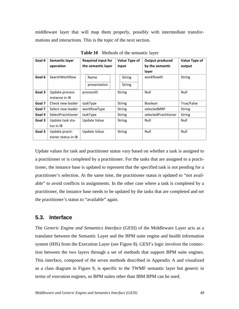
Middleware and Generic Engine and Semantics Interface (GESI) 48
middleware layer that will map them properly, possibly with intermediate transfor-
mations and interactions. This is the topic of the next section.
Table 10 Methods of the semantic layer
Goal # Semantic layeroperation
Required input forthe semantic layer
Value Type ofinput
Output producedby the semanticlayer
Value Type ofoutput
Goal 6 SearchWorkflow Name
presentation
String
String
workflowID String
Goal 3 Update processinstance in IB
processID String Null Null
Goal 7 Check new leader taskType String Boolean True/FalseGoal 7 Select new leader workflowType String selectedMRP StringGoal 4 SelectPractitioner taskType String selectedPractitioner StringGoal 3 Update task sta-
tus in IBUpdate Value String Null Null
Goal 3 Update practi-tioner status in IB
Update Value String Null Null
Update values for task and practitioner status vary based on whether a task is assigned to
a practitioner or is completed by a practitioner. For the tasks that are assigned to a practi-
tioner, the instance base is updated to represent that the specified task is not pending for a
practitioner’s selection. At the same time, the practitioner status is updated to “not avail-
able” to avoid conflicts in assignments. In the other case where a task is completed by a
practitioner, the instance base needs to be updated by the tasks that are completed and set
the practitioner’s status to “available” again.
5.3. Interface
The Generic Engine and Semantics Interface (GESI) of the Middleware Layer acts as a
translator between the Semantic Layer and the BPM suite engine and health information
system (HIS) from the Execution Layer (see Figure 8). GESI’s logic involves the connec-
tion between the two layers through a set of methods that support BPM suite engines.
This interface, composed of the seven methods described in Appendix A and visualized
as a class diagram in Figure 9, is specific to the TWMF semantic layer but generic in
terms of execution engines, so BPM suites other than IBM BPM can be used.

Middleware and Generic Engine and Semantics Interface (GESI) 49
Execution Layer
Semantic Layer
MIIBM
BPM suite engine
Middlew
are
Middlew
are
HIS
New Patient
Name,presentationype
selectWorkflow
(name,
presentationType)
workflowID
processID
updateIB(processID
)
taskStatustaskList
checkNew
MR
P(w
orkflowT
ype)
selectedMRP
selectPractitioner
(taskType)
practitionerIDtaskID processID
Check C
losedT
asks andupdate the IB
taskList
GESI Implementation
CreateP
atient(name,presentation)
exception
Figure 8 GESI overview
The Semantic Layer’s Team and Workflow Controller (TWC) component and the Execu-
tion Layer’s Workflow Execution Engine (WEE) and HIS components interoperate
through GESI. Figure 8 illustrates the seven generic methods of the interface (also high-
lighted in the class diagram of Figure 9), which require specific implementations for a
given BPM suite. The arrows headed from GESI to the Semantic Layer are indirect Z3
invocations that are sent via the MIIBM and the TWC.

Middleware and Generic Engine and Semantics Interface (GESI) 50
Figure 9 GESI class diagram
5.3.1 Interface Sequence Diagram
This section presents the order of invocations of GESI’s methods using a UML sequence
diagram (Figure 10). A GESI instance and a TWC instance are first created upon the noti-
fication of the HIS of the creation in the system of a patient with a specific presentation.
In Figure 10, the interactions between TWC and GESI are generic and do not change. In
the Semantic Layer, TWC was modified and restructured to use GESI’s methods. How-
ever, the methods between the GESI implementation and the BPM suite are dependent on
the nature of the BPM suite selected. As an example, the figure illustrates the use of the
IBM BPM interface for the interactions between GESI and the BPM suite.
GESI’s implementation must exploit the Java thread mechanism to allow multiple
executions of the same workflow or of different workflows at a time. In Figure 10, the
green boxes represent loops (LOOP while the condition is true) and conditional behav-
iour (the two OPT boxes, which execute only if the conditions are true). The use of the
reportExceptions method is not illustrated here as this message can be sent at any mo-
ment during the loop.

Middleware and Generic Engine and Semantics Interface (GESI) 51
Figure 10 Sequence diagram capturing GESI’s usage, with IBM BPM as a BPM suite
example
5.3.2 Middleware Package and GESI Data Structures
Middleware is often responsible for data transformation and for relaying messages. This
is also the case here. There are seven methods in GESI that support such transformations
and relays within the scope of our research’s objectives. These are supported by two ad-
ditional data structures in the middleware, as shown in the UML package diagram
in Figure 11.

Middleware and Generic Engine and Semantics Interface (GESI) 52
Figure 11 Package diagram of the middleware
The WorkflowID class is a data type representing a unique identifier for a workflow de-
fined in the BPM Suite. Since such an identifier can also be composed of more than one
sub-identifiers. For example, a given suite (such as IBM BPM) could use a business pro-
cess definition identifier (bpdID) and a process application identifier (processAppID).
The WorkflowID class, shown in Figure 12 is designed for handling these situations. In
the case where only one identifier string is sufficient for a given BPM suite, the bpdID
field is used.
Figure 12 WorkflowID class diagram
In addition, our middleware also contains a generic way to capture task information be-
tween the semantic layer and the middleware layer. Figure 13 is a class diagram created
for TaskInfo. A TaskInfo object has five attributes:
The task instance (TaskID).
The type of the task, starting with prefix “t_” (e.g., “t_surgery”).
pkg middleware
<<Java Interface>>GESI
WorkflowID
TaskInfo

Middleware and Generic Engine and Semantics Interface (GESI) 53
The type of the target workflow if the task is directing to a sub-workflow. This at-
tribute exists when there is a need for a new leader. (e.g., when taskType =
“t_new_MRP”, then a workflowType value is needed, say “w_day_2”).
The status of the task (taskStatus), which is used for filtering the task list (e.g.,
“Received”, “Closed”).
The assignee of the task, which represents the practitioner selected for the task.
Figure 13 TaskInfo class diagram
5.3.3 GESI Signatures
Table 11 lists GESI’s seven methods and indicate which middleware requirements
from Table 3 they satisfy. Note that collectively, these methods satisfy all of the middle-
ware requirements.
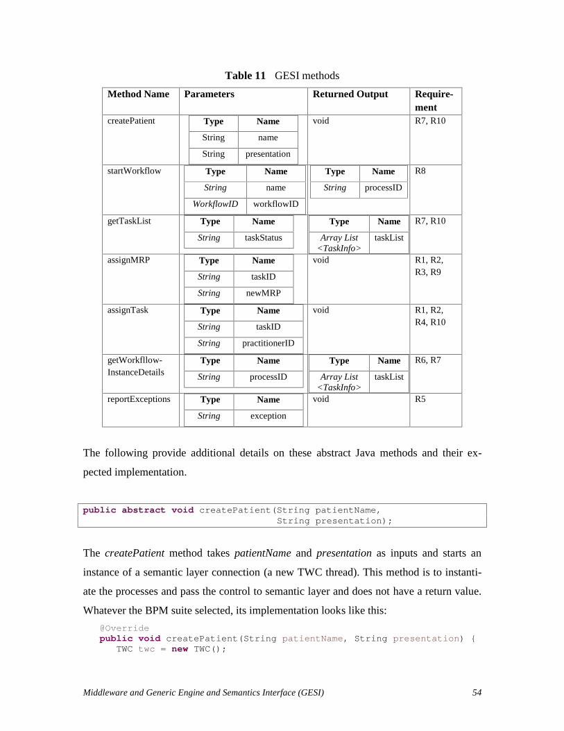
Middleware and Generic Engine and Semantics Interface (GESI) 54
Table 11 GESI methods
Method Name Parameters Returned Output Require-ment
createPatient Type Name
String name
String presentation
void R7, R10
startWorkflow Type Name
String name
WorkflowID workflowID
Type Name
String processID
R8
getTaskList Type Name
String taskStatus
Type Name
Array List<TaskInfo>
taskList
R7, R10
assignMRP Type Name
String taskID
String newMRP
void R1, R2,R3, R9
assignTask Type Name
String taskID
String practitionerID
void R1, R2,R4, R10
getWorkfllow-InstanceDetails
Type Name
String processID
Type Name
Array List<TaskInfo>
taskList
R6, R7
reportExceptions Type Name
String exception
void R5
The following provide additional details on these abstract Java methods and their ex-
pected implementation.
public abstract void createPatient(String patientName,String presentation);
The createPatient method takes patientName and presentation as inputs and starts an
instance of a semantic layer connection (a new TWC thread). This method is to instanti-
ate the processes and pass the control to semantic layer and does not have a return value.
Whatever the BPM suite selected, its implementation looks like this:
@Overridepublic void createPatient(String patientName, String presentation) {
TWC twc = new TWC();
Middleware and Generic Engine and Semantics Interface (GESI) 55
wc.createPatient(patientName, presentation, this); }
where this sends the new TWC a reference to the GESI object that created that TWC.
public abstract String startWorkflow(String name,WorkflowID workflowID);
The startWorkflow method takes name and workflowID as inputs to start a workflow in-
stance in the BPM suite and returns the instantiated process identifier as a string.
public abstract ArrayList<TaskInfo> getTaskList(String taskStatus);
The getTaskList method takes a task status as input and returns the list of tasks having
this status in the running process instance. In other words, this method filters the detailed
information received from an instantiated process instance.
public abstract void assignMRP(String newMRP, String task_ID);
When a “t_New_MRP” task is identified, the semantic layer sends the message about
selected new leader to the interface, so that the interface can relay this information to the
BPM Suite. As most BPM suites are not sufficiently expressive to consider the leader in a
process, this information is managed by the semantic layer but often stored as a variable
at the BPM level. The method receives the newMRP variable and the taskID of the asso-
ciated task and does not return any value.
public abstract void assignTask(String task_ID, String practitioner);
After the semantic layer has selected the most responsible practitioner for the received
task, task assignment information is sent to the interface on a per task basis. The interface
takes the taskID and the practitionerID as an input and does not return anything.
public abstract ArrayList<TaskInfo> getWorkflowInstanceDetails(String processID);

Middleware and Generic Engine and Semantics Interface (GESI) 56
This method receives a processID as an input to get the list of details of all tasks in this
process instance. Instead of filtering with the taskStatus as done by getTaskList, this
method retrieves all the tasks.
public abstract void reportException(String exception);
This method is meant to be invoked by the BPM suite (e.g., through messages or Java
exceptions) in order to inform the semantic layer about an exception that could not be
handled at the BPM level. Its implementation is left for future work.
5.4. Middleware with GESI Implementation for IBM BPM
In this section, GESI is implemented for a specific BPM suite - IBM BPM. This imple-
mentation uses some methods to enable GESI’s interactions with the BPM engine (sec-
tion 5.1.3). Figure 10 gives a closer look at GESI’s implementation for IBM BPM.
Semantic Layer
Execution Layer
MIIBM
BPM suite engine
Middlew
are
Middlew
are
HIS
New
Patient
GE
SI4IB
M
Name,presentationype
selectWorkflow
(name,
presentationType) workflowID
BPDID,BPAID
processID
processID
updateIB(processID
)
taskStatus
processID
JSONOBJECT
taskList
checkNew
MR
P(w
orkflowT
ype)
selectedMRP
“MRP”,selectedMRP
JSONOBJECTselectP
ractitioner(taskT
ype)
practitionerIDtaskID
practitionerID,taskID
JSONOBJECT
processID
Check C
losedT
asks and updatethe IB
JSONOBJECT
taskList
processID“patientName”,
patientName
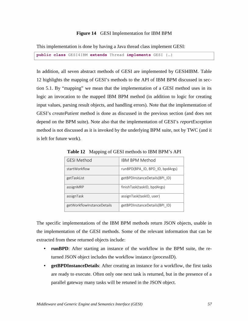
Middleware and Generic Engine and Semantics Interface (GESI) 57
Figure 14 GESI Implementation for IBM BPM
This implementation is done by having a Java thread class implement GESI:
public class GESI4IBM extends Thread implements GESI {…}
In addition, all seven abstract methods of GESI are implemented by GESI4IBM. Table
12 highlights the mapping of GESI’s methods to the API of IBM BPM discussed in sec-
tion 5.1. By “mapping” we mean that the implementation of a GESI method uses in its
logic an invocation to the mapped IBM BPM method (in addition to logic for creating
input values, parsing result objects, and handling errors). Note that the implementation of
GESI’s createPatient method is done as discussed in the previous section (and does not
depend on the BPM suite). Note also that the implementation of GESI’s reportException
method is not discussed as it is invoked by the underlying BPM suite, not by TWC (and it
is left for future work).
Table 12 Mapping of GESI methods to IBM BPM’s API
GESI Method IBM BPM Method
startWorkflow runBPD(BPA_ID, BPD_ID, bpdArgs)
getTaskList getBPDInstanceDetails(BPI_ID)
assignMRP finishTask(taskID, bpdArgs)
assignTask assignTask(taskID, user)
getWorkflowInstanceDetails getBPDInstanceDetails(BPI_ID)
The specific implementations of the IBM BPM methods return JSON objects, usable in
the implementation of the GESI methods. Some of the relevant information that can be
extracted from these returned objects include:
runBPD: After starting an instance of the workflow in the BPM suite, the re-
turned JSON object includes the workflow instance (processID).
getBPDInstanceDetails: After creating an instance for a workflow, the first tasks
are ready to execute. Often only one next task is returned, but in the presence of a
parallel gateway many tasks will be retuned in the JSON object.

Middleware and Generic Engine and Semantics Interface (GESI) 58
assignTask: The JSON object input after assigning a task includes the task in-
stance and the user name information.
finishTask: The JSON object returned in this case includes the related task in-
stance’s status as “Closed” and the following task’s status as “Received”.
The implementation of the GESI methods with the IBM BPM API led to the following
design decisions, also illustrated in the right part of the sequence diagram of Figure 10:
startWorkflow: At first, this method puts the name input into the process
bpdArgs parameters object (explained in 5.1.3). Secondly, it invokes the runBPD
method while separating the input workflowID into BPDID and BPAID parame-
ters (so that IBM BPM can understand the inputs).
getTaskList: IBM BPM offers a getInbox method to get received tasks. However,
this method returns only one received task. If there is a BPMN parallel gateway
beginning with two tasks that needs to be executed in parallel, then two task in-
stances must be received at the same time from the BPM suite’s engine. The Se-
mantic layer needs these two task instances in order to identify the most responsi-
ble assignments for the set of tasks. To handle parallel tasks as needed, the get-
BPDInstanceDetails method (Table 9) is invoked instead. All tasks reachable
from a parallel gateway are returned in a task list (using the TaskInfo data struc-
ture of Figure 13), and then the results are filtered according to the desired task
status before being returned to the TWC.
assignMRP: This method is invoked when an artificial task requiring a new lead-
er (usually found at the beginning of a top-level process or sub-process in the
BPMN model) is instantiated. First the MRP (leader) variable is put into the pro-
cess bpdArgs parameter object. In order to represent the patient and the leader in
IBM BPM, global variables associated to workflow instances are used for storage.
Then, since this artificial task is not really assigned to a practitioner (it is assumed
to be a system task), this task needs to be closed. IBM BPM’s finishTask method
(see Table 8) is invoked automatically to close the new leader checking task.
Middleware and Generic Engine and Semantics Interface (GESI) 59
assignTask: The received taskID is converted to an Integer (as IBM BPM uses
integers for task identifiers) and the assignTask method (see Table 6) of the BPM
suite is invoked.
getWorkflowInstanceDetails: The method also invokes the getBPDInstanceDe-
tails method (see Table 9) of IBM BPM. However, no unlike for getTaskList, no
filtering is applied before returning the resulting list of tasks.
When a Business Process Definition (BPD) is created with IBM BPM Process Designer
(see for example the BPMN processes in Appendix B), it needs to be exposed, i.e., pub-
lished to enable external interactions. The semantic layer needs the BPD identifiers for
mapping purposes. Before executing a workflow, these values are identified and stored in
the instance base. Process Designer allows us to expose the business process definitions.
After starting the workflow, we can monitor inside Process Designer whether tasks are in
the ‘Received’ status. When the task is assigned, related practitioners see a notification
on their device with the implementation of these screens.
This implementation supports the management of some exceptions. For example,
the leader can be notified if a task is assigned to a practitioner who has not yet confirmed
accepting the task and the time left to the due date of this task is below a certain defined
threshold. Such exceptions are handled within IBM BPM, without the intervention of the
semantic layer.
5.5. Chapter Summary
In this chapter, the middleware that allows the semantic layer of the Team and Workflow
Manager Framework to interoperate with a BPM suite is presented. The interface (GESI)
decouples the semantic layer from the underlying execution layer, and the middleware’s
logic provides appropriate translations between the concepts, commands, and data struc-
tures involved. GESI is composed of seven abstract methods and the middleware package
also includes a few additional classes for capturing important information about work-
flows and tasks. The TWC was also restructured to exploit the GESI methods. GESI was

Middleware and Generic Engine and Semantics Interface (GESI) 60
also implemented for a specific and popular BPM suite, namely IBM Business Process
Manager.
The next chapter uses this implementation of the middleware in proof-of-concept
scenarios to assess the feasibility of the overall approach.

Proof-of-Concept Scenarios 61
Chapter 6. Proof-of-Concept Scenarios
This chapter illustrates the feasibility and capabilities of the middleware layer based on
two clinical workflow scenarios, with full coverage of the requirements given in Table 3.
These proof-of-concept scenarios use the assumptions given in Table 4.
6.1. Overview of Two Selected Clinical Workflows
Two simplified but realistic workflows, whose models are given in Appendix B, have
been selected to instantiate scenarios. A scenario is a particular execution run of a clini-
cal workflow, covering along the way ontology concepts/relations and middleware re-
quirements for supporting IHT dynamics. The first workflow (Figure 22) is a simplified
radical prostatectomy, which describes the in-patient management after surgical removal
of all or part of the prostate gland in a male patient (The Ottawa Hospital, 2010), whereas
the second workflow (Figure 23) describes acute stroke management and is derived from
UK guideline (NICE, 2008).
The simplified clinical workflows from Appendix B are modelled formally with
BPMN using IBM BPM Process Designer. They provide the required coverage of com-
mon BPMN constructs, including:
Sequential activities, annotated with required capability levels.
Decision gateway nodes, to make sure that only the selected task is handled by the
middleware.
Parallel gateway nodes, to make sure that many tasks can be assigned concurrent-
ly by the middleware.
Activities refined as sub-processes, with required specialty levels that may lead to
new leader assignments.
The acute stroke management workflow includes sequence, alternative, and concurrent
tasks (but no sub-process). Decision gateways let practitioners decide which alternative
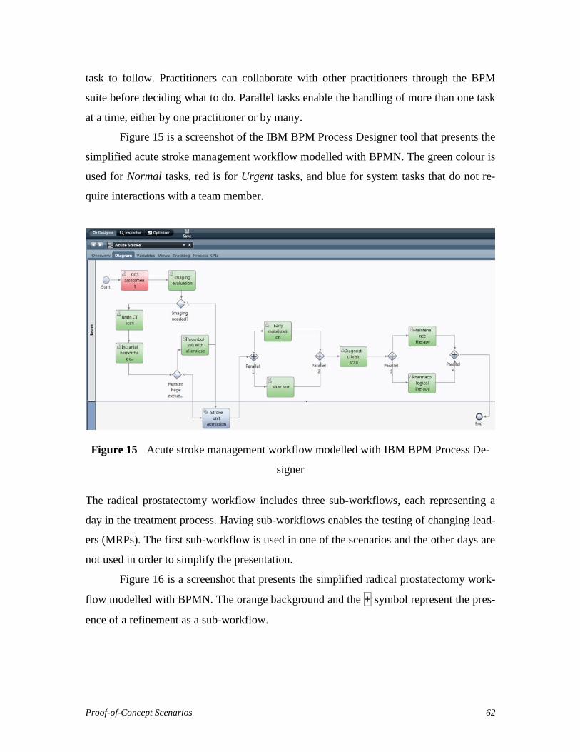
Proof-of-Concept Scenarios 62
task to follow. Practitioners can collaborate with other practitioners through the BPM
suite before deciding what to do. Parallel tasks enable the handling of more than one task
at a time, either by one practitioner or by many.
Figure 15 is a screenshot of the IBM BPM Process Designer tool that presents the
simplified acute stroke management workflow modelled with BPMN. The green colour is
used for Normal tasks, red is for Urgent tasks, and blue for system tasks that do not re-
quire interactions with a team member.
Figure 15 Acute stroke management workflow modelled with IBM BPM Process De-
signer
The radical prostatectomy workflow includes three sub-workflows, each representing a
day in the treatment process. Having sub-workflows enables the testing of changing lead-
ers (MRPs). The first sub-workflow is used in one of the scenarios and the other days are
not used in order to simplify the presentation.
Figure 16 is a screenshot that presents the simplified radical prostatectomy work-
flow modelled with BPMN. The orange background and the + symbol represent the pres-
ence of a refinement as a sub-workflow.
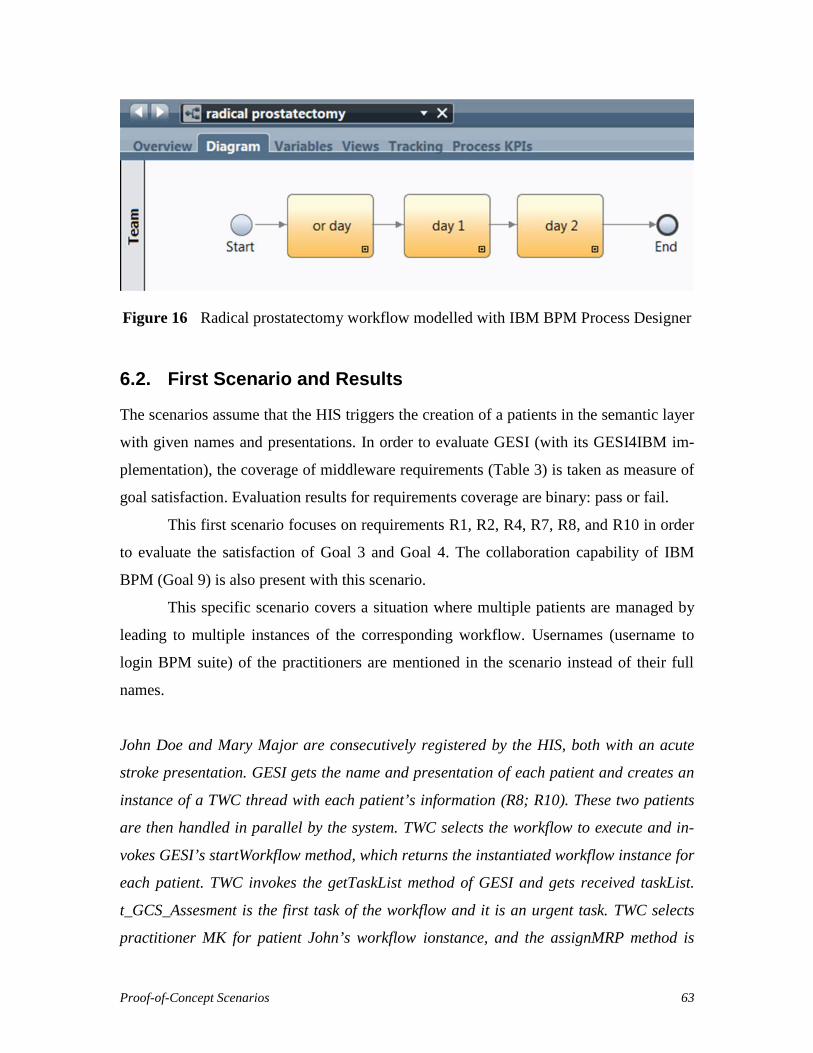
Proof-of-Concept Scenarios 63
Figure 16 Radical prostatectomy workflow modelled with IBM BPM Process Designer
6.2. First Scenario and Results
The scenarios assume that the HIS triggers the creation of a patients in the semantic layer
with given names and presentations. In order to evaluate GESI (with its GESI4IBM im-
plementation), the coverage of middleware requirements (Table 3) is taken as measure of
goal satisfaction. Evaluation results for requirements coverage are binary: pass or fail.
This first scenario focuses on requirements R1, R2, R4, R7, R8, and R10 in order
to evaluate the satisfaction of Goal 3 and Goal 4. The collaboration capability of IBM
BPM (Goal 9) is also present with this scenario.
This specific scenario covers a situation where multiple patients are managed by
leading to multiple instances of the corresponding workflow. Usernames (username to
login BPM suite) of the practitioners are mentioned in the scenario instead of their full
names.
John Doe and Mary Major are consecutively registered by the HIS, both with an acute
stroke presentation. GESI gets the name and presentation of each patient and creates an
instance of a TWC thread with each patient’s information (R8; R10). These two patients
are then handled in parallel by the system. TWC selects the workflow to execute and in-
vokes GESI’s startWorkflow method, which returns the instantiated workflow instance for
each patient. TWC invokes the getTaskList method of GESI and gets received taskList.
t_GCS_Assesment is the first task of the workflow and it is an urgent task. TWC selects
practitioner MK for patient John’s workflow ionstance, and the assignMRP method is
Proof-of-Concept Scenarios 64
invoked accordingly. GESI relays this assignment to the BPM suite (R1; R2). TWC de-
tects there is no more available practitioner to assign for patient Mary. The reasoner
detects a practitioner who has the appropriate competencies, but who is busy with a
normal task (t_imaging_evaluation) in some other patient’s workflow. The semantic layer
releases the practitioner from the normal task and assigns her to Mary’s
t_GCS_Assessment task. GESI relays these requests to the BPM suite (R1; R4; R2; R10).
When the practitioner finishes the task from the notification screen, TWC asks for the
new “Received”task list from GESI and gets the t_imaging_evaluation task (R7). TWC
selects a practitioner for the new task (with a preference for the existing practitioner if
still available), and invokes the assignTask method to apply the assignment in the BPM
Suite. t_imaging_evaluation needs a decision from the practitioner, i.e., choice of treat-
ment in the process. The practitioner collaborates with his/her colleagues while deciding
and then TWC gets this choice information by invoking GESI’s getWorkflowInstanceDe-
tails method and asks for the new “Received” task list (R7; R10).
6.2.1 Create Patient, Start Workflow and Get Task List
The HIS instantiates a new GESI4IBM implementation for each patient and invokes the
createPatient method with information on John and Mary.
gesiJohn.createPatient("John Doe", "p_stroke");gesiMary.createPatient("Mary Major", "p_stroke");
Each invocation creates a TWC instance and transfers the control to the created TWC to
manage the patient. The semantic layer decides which workflow to execute with the giv-
en presentation (acute stroke) and sends the selected workflowID to the corresponding
GESI4IBM instance through its TWC. startWorkflow is the method invoked by TWC
with the selected workflowID (R10).
The message with patient name is sent to the BPM suite for representation pur-
poses in the practitioner notification screens. workflowID is an instance of a class that
converts required identifiers to start a workflow instance in the BPM suite. IBM BPM
creates process instances (2224 and 2225) for John and Mary respectively (R8). These
instances can be monitored in the IBM BPM Monitoring tool. As can be seen from Figure

Proof-of-Concept Scenarios 65
17, when a process instance is created, a token highlights the first task to be performed,
which is set to a Received status (without any assignment). Each BPM suite’s instance
identified is returned to GESI (via a JSON object attached to a 200 OK message).
Figure 17 Monitoring of created process instances
TWC invokes the getTaskList method to get the received tasks list. This method returns a
list of tasks in the type of ArrayList<TaskInfo>. TWC also provides a “Received” task
status to filter tasks in the instantiated workflow instance (R7). In this scenario,
t_GCS_Assesment is the first task of w_Acute_Stroke instantiated, and 4219 and 4220 are
the task instance identifiers returned for John’s and Mary’s workflows, respectively. The
BPM engine waits until an assignment action is performed.
After getting the list of received tasks for the patients, the Semantic Layer selects
the practitioners the most adequate to execute the tasks.
6.2.2 Assign Task and Get Workflow Instance Details
The first TWC instance returns practitioner MK for John’s workflow. Its GESI4IBM re-
lays this assignment to the BPM suite (R1; R2; R10) via the assignTask method. TWC
invokes the method with the selected practitioner and the task instance identifier.

Proof-of-Concept Scenarios 66
The practitioner assignment can be monitored inside the Monitoring tool and the
assignment can be seen with the silhouette icon (top-left of the task) changed to the as-
signed practitioner’s picture. Figure 18 is a screenshot presenting the GCS assessment
task assigned to practitioner MK.
Figure 18 Monitoring of an assigned practitioner
t_GCS_Assessment is an urgent task and the semantic layer detects there is no available
practitioner to assign for patient Mary. The reasoner detects that practitioner DR, who has
the required competencies, is busy with a normal task (t_imaging_evaluation) in another
patient’s workflow. The semantic layer selects to release DR from the normal task and
assign her to Mary’s t_GCS_Assessment urgent task. GESI4IBM relays this request to the
BPM suite (R1; R4) with assignTask(“4220”, “DR”).
For reassignment of the normal task, GESI’s assignTask method can again be in-
voked by the semantic layer (R4). After completing the GCS assessment task, the status
of the task changes to Completed. GESI4IBM’s internal checking mechanism detects
closed tasks and sends associated task instances to the semantic layer to update the in-
stance base.
Execution of John’s workflow instance reaches the imaging evaluation task with
task type t_imaging_evaulation and the task_ID 4225. Because practitioner MK executed
a task on this workflow instance earlier, she is marked as a suggested practitioner for fu-
ture tasks in the instance. The semantic layer detects that MK is a suggested practitioner

Proof-of-Concept Scenarios 67
and that she is also eligible to execute the next task. MK is hence selected again to exe-
cute the next task, imaging evaluation. Figure 19 presents a screenshot of the monitoring
of the suggested member’s assignment.
Figure 19 Monitoring of suggested member assignment
The workflow instance execution reaches a decision gateway after imaging evaluation, so
this task needs to be closed with a decision. Practitioner MK is prompted to make a deci-
sion in her notification screen.
Before completing this task, MK wants to inform the leader about her decision.
MK selects the leader, WM, inside the notification screen and comments the results re-
ceived from the previous task execution. Collaborative discussion between practitioners
MK and WM is supported by IBM BPM. This highlights a BPM suite’s collaboration
benefit (Goal 9), which is an important tool in a team for a successful patient treatment
(see 2.4.)
MK completes is imaging evaluation task, with a choice of brain CT scanning for patient
John Doe. Figure 20 presents MK’s notification screen for this choice.

Proof-of-Concept Scenarios 68
Figure 20 Practitioner decision screen for a brain CT scan
MK completes the task and the status of the task changes to Completed. GESI4IBM re-
lays this information to the semantic layer and the workflow continues with the choice of
Brain CT Scan.
Table 13 Middleware requirements satisfied by the first scenario
R# Description Pass/FailR1 Capability-based assignments shall be relayed from the semantic layer
to the BPM suite’s engine.Pass
R2 Task/Process assignments shall be relayed from the semantic layer tothe BPM suite’s engine.
Pass
R4 Reassignment of team members shall be relayed from the semanticlayer to the BPM suite’s engine.
Pass
R7 The middleware shall enable the semantic layer to query and filterinformation from the BPM suite’s engine.
Pass
R8 The middleware shall enable the semantic layer to instantiate a work-flow instance in the BPM suite’s engine.
Pass
R10 Workflow, team member, and leader selection requests shall be re-layed from interface to semantic layer.
Pass
As highlighted in Table 13, tests for R1, R2, R4, R7, R8 and R10 passed with direct API
implementations or with additional designed methods.
(R1) Capability-based assignments are relayed to the BPM engine with the as-
signTask method.
(R2) Since leader information is not generated when the workflow is instantiated,
a bpdArgs value is passed to the process without the leader value. However, pro-
cess assignments of leader information are stored in objects at the implementation
level.
(R4) Reassignments are relayed with the same assignTask method. A release
method for a task could not be found, but it is not necessary here.
(R7) The existing getInbox method of the IBM BPM API could not be used for
handling parallel processes, so the getTaskList method was implemented by filter-

Proof-of-Concept Scenarios 69
ing the results of an existing API method (getBPDInstanceDetails) and changing
the algorithm to get received tasks in the workflow.
(R8) Workflow identifiers are relayed with the startWorkfow method and the
workflow instance identifier is returned.
(R10) Selection requests are relayed to the BPM suite with GESI method invoca-
tions from the TWC.
Note that the simultaneous management of patients is handled while achieving capability-
based assignments and team dynamics in IHTs. The collaboration capabilities of the un-
derlying BPM suite are also exploited with useful benefits.
6.3. Second Scenario and Results
In the second scenario, requirements R2, R3, R6, R7, R8, R9, and R10 are tested to eval-
uate the satisfaction of Goal 5 and Goal 7. The presentation used in this scenario (radical
prostatectomy, see Figure 22 in Appendix B) includes sub-workflows corresponding to
each day of the treatment process. Execution of each sub-workflow requires a clinical
specialty that is used to establish whether the current leader can continue or if there is a
need for a new leader. The scenario presented here covers the operating room (OR) day
sub-workflow shown in Figure 21.

Proof-of-Concept Scenarios 70
Figure 21 OR day sub-workflow of the radical prostatectomy workflow
Patient Paolo is registered by the HIS with a radical prostatectomy presentation. TWC
finds workflow identifiers associated with the w_radical_prostatectomy clinical workflow
and the corresponding process is instantiated in the BPM suite. The OR Day sub-
workflow’s first task is aboutidentifying a new leader (MRP), with task type
“t_new_MRP”. This task also has a workflowType variable that defines the type of the
workflow for proper leader selection. This artificial task is finished via GESI4IBM’s
method invocation since it was not assigned to any practitioner. Next, the workflow
reaches a gateway having parallel processes. In this scenario, four tasks need to be re-
ceived, assigned and executed in parallel. TWC handles this parallel task assigning and
execution and GESI4IBM relays all received tasks one at a time.
6.3.1 Create Patient, Start Workflow and Get TaskList
The HIS creates a new patient with the patient’s name and presentation:
gesiPaolo.createPatient("Paolo", "p_prostatectomy");
GESI4IBM passes the control to a new TWC with the createPatient method. TWC finds
workflow identifiers associated with the w_radical_prostatectomy workflow (R9). The
corresponding process is instantiated in the BPM suite through the invocation of GESI’s
startWorkflow method. A process instance (2236) is created and a JSON object is re-
turned to update the middleware with information about instance 2236. GESI’s start-
Workflow method returns “2236” to the semantic layer. (R6).
Once the instance base is updated with the new instantiated process_ID, TWC in-
vokes getTaskList. The w_radical_prostatectomy workflow starts with the OR day sub-
workflow and needs to check whether a new leader is required. When a task having the
type t_new_MRP is detected by the semantic layer, a new leader selection is decided de-
pending on the same task workflowType variable. The OR day sub-workflow’s first
t_new_MRP task has a w_or_day value. The getTaskList method returns the taskList as
an array of taskInfo objects. When a task type is t_new_MRP, workflowType exists for
the taskInfo.
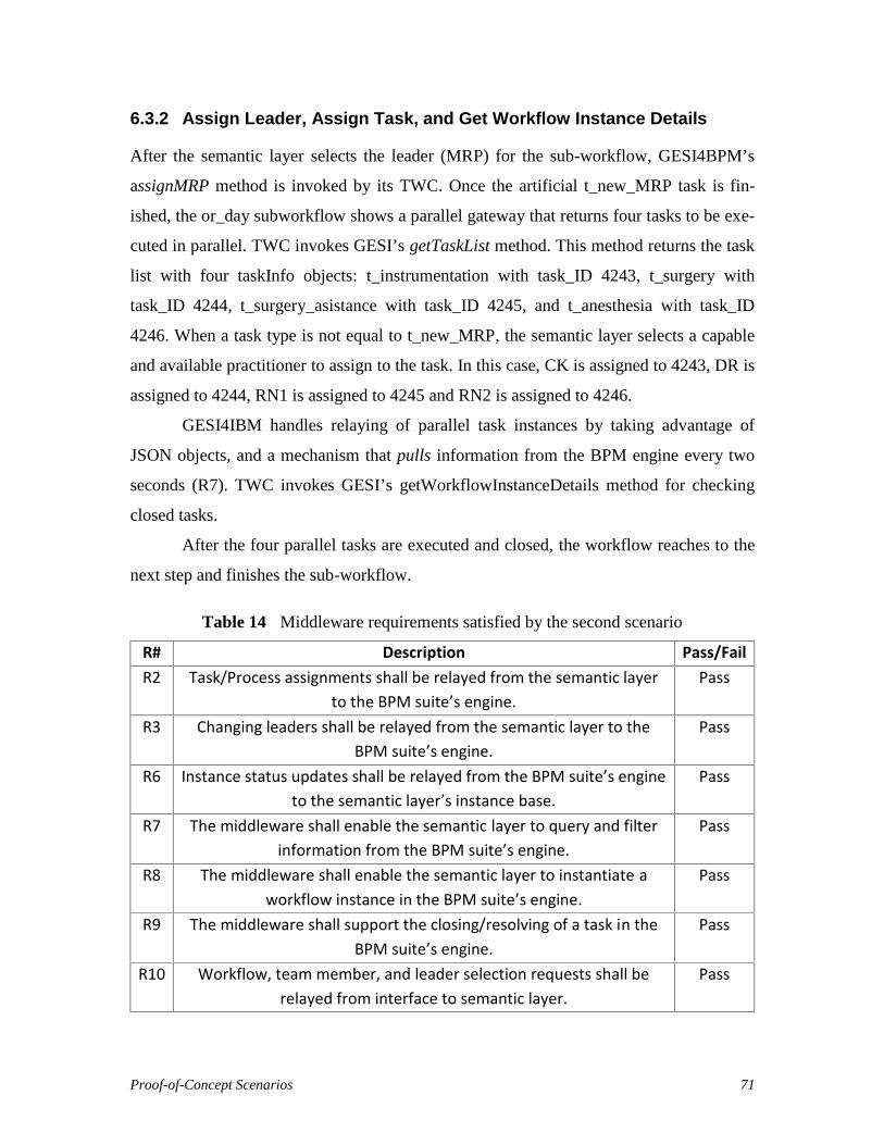
Proof-of-Concept Scenarios 71
6.3.2 Assign Leader, Assign Task, and Get Workflow Instance Details
After the semantic layer selects the leader (MRP) for the sub-workflow, GESI4BPM’s
assignMRP method is invoked by its TWC. Once the artificial t_new_MRP task is fin-
ished, the or_day subworkflow shows a parallel gateway that returns four tasks to be exe-
cuted in parallel. TWC invokes GESI’s getTaskList method. This method returns the task
list with four taskInfo objects: t_instrumentation with task_ID 4243, t_surgery with
task_ID 4244, t_surgery_asistance with task_ID 4245, and t_anesthesia with task_ID
4246. When a task type is not equal to t_new_MRP, the semantic layer selects a capable
and available practitioner to assign to the task. In this case, CK is assigned to 4243, DR is
assigned to 4244, RN1 is assigned to 4245 and RN2 is assigned to 4246.
GESI4IBM handles relaying of parallel task instances by taking advantage of
JSON objects, and a mechanism that pulls information from the BPM engine every two
seconds (R7). TWC invokes GESI’s getWorkflowInstanceDetails method for checking
closed tasks.
After the four parallel tasks are executed and closed, the workflow reaches to the
next step and finishes the sub-workflow.
Table 14 Middleware requirements satisfied by the second scenario
R# Description Pass/FailR2 Task/Process assignments shall be relayed from the semantic layer
to the BPM suite’s engine.Pass
R3 Changing leaders shall be relayed from the semantic layer to theBPM suite’s engine.
Pass
R6 Instance status updates shall be relayed from the BPM suite’s engineto the semantic layer’s instance base.
Pass
R7 The middleware shall enable the semantic layer to query and filterinformation from the BPM suite’s engine.
Pass
R8 The middleware shall enable the semantic layer to instantiate aworkflow instance in the BPM suite’s engine.
Pass
R9 The middleware shall support the closing/resolving of a task in theBPM suite’s engine.
Pass
R10 Workflow, team member, and leader selection requests shall berelayed from interface to semantic layer.
Pass

Proof-of-Concept Scenarios 72
As highlighted in Table 14, tests for R2, R3, R6, R7, R8, R9 and R10 passed with direct
API implementations or with additional designed methods. The same explanations pro-
vided in the previous scenario apply here as well. In addition:
(R6) Instance status updates relayed from the BPM suite’s engine to the semantic
layer’s instance base and synchronization are achieved with JSON objects.
(R9) The artificial t_New_MRP task is used in the beginning of every sub-
workflow to enable the semantic layer to recognize which type of sub-workflow is
being executed. Hence, the need for a new leader is checked by the semantic layer
for the sub-workflow. However, since this task is not assigned to any practitioner,
GESI closes the task explicitly after the semantic layer selects the leader.
Note that the handling of parallel tasks and of leaders associated to workflows are again
handled properly in this scenario.
6.4. Chapter Summary
Two scenarios were presented for evaluating the satisfaction of Team Dynamics, Capa-
bility-based and Task/Process based assignments, Leaders, and Collaboration (Goals 3,
4, 5, 7, and 9) via nine middleware requirements. The results are all positive. Require-
ment R5 and Goal 8, related to exception handling, were not tested as this capability is
not yet implemented by the middleware layer and is left for future work.
Further evaluations and a discussion of threats and limitations are presented in the
next chapter.
Evaluation and Discussion 73
Chapter 7. Evaluation and Discussion
This chapter discusses the thesis’ main contribution (the middleware) in its containing
system by comparing it against closely related work in terms of achieving the goals relat-
ed to the support of IHT dynamics. Then, the generality of the solution is argued by
providing an overview mapping between the middleware’s interface (GESI) and the APIs
of five other BPM suites, hence showing the independence of the semantic layer from
IBM BPM. Finally, threats to the validity of this work are discussed.
7.1. Comparison with Closely Related Work
This section presents a brief comparison of this research with existing related approaches
that were also implemented. The middleware and GESI enable the interoperability be-
tween the specific semantic layer described by Kezadri et al. (2015) and a BPM suite to
support IHT dynamics in clinical workflows. The previous two chapters showed that this
approach works with IBM BPM as a BPM suite. Table 1 already summarized how well
related approaches satisfied the nine goals. Table 15 reuses Table 1 and adds one more
row for the approach described in this thesis.
Among related approaches, Cabanillas et al. (2015) and Wilk et al. (2016) are the
ones that score the highest in terms of enabling support of IHT dynamics. Both have a
satisfactory support for the first six goals, just like the thesis approach. However, Caba-
nillas et al.’s approach lacks support for the management of frequently changing leaders,
exceptions, and collaboration. Wilk et al.’s approach supports leaders, but it only partially
supports exception handling. In addition, Wilk et al.’s approach does not have sufficient
support for collaboration since it just focuses on workflow execution.
The thesis approach fills this latter gap. Not only does it support selection of lead-
ers, but it automatically inherits good collaboration support by integrating with a BPM
suite. Although the thesis approach does not fully support exception handling (except

Evaluation and Discussion 74
those that are handled at the BPM suite level), it at least provides some basioc mechanism
for dealing with selected few.
Table 15 Comparison of the thesis approach with closely-related work
1:Po
pula
rity
2:Ex
pres
sive
ness
3:Te
am D
ynam
ics
4:Ca
pabi
lity-
Base
d
5: T
ask/
Proc
ess
Assi
gnm
ents
6: H
ealth
care
Conc
epts
7: L
eade
rs
8: E
xcep
tions
9:Co
llabo
ratio
n
Cabanillas et al. (2015) Y Y Y Y Y Y N N NDeveloperWorks (2014) Y Y +/- +/- Y N +/- +/- YPapapanagiotou et al. (2012) N +/- +/- N +/- Y Y Y NPrater et al. (2012) Y Y N N N N N N YPrinyapol et al. (2009) (DPWFM) +/- +/- +/- +/- Y Y +/- N NSchmidt and Kunzmann (2006) +/- +/- Y Y Y Y Y N NWilk et al. (2016) (MET4) Y Y Y Y Y Y Y +/- N
This thesis Y Y Y Y Y Y Y +/- Y
In conclusion, the middleware developed and described in the thesis satisfies the best the
nine goals identified for supporting IHT dynamics, with opportunities for extending in
terms of exception handling.
7.2. Potential Support of Other BPM Suites
Most BPM suites provide an API (accessible directly or via some REST or Web service)
that enables the management of workflows. The richness of these APIs in terms of capa-
bilities varies depending on the suite. However, most of these BPM suites provide basic
capabilities for creating and monitoring workflows and activities, and for assigning activ-
ities, as concluded from a review of independent comparison results about capabilities
and scopes of BPM suites (Kamil, 2014; Craggs, 2009; Craggs, 2010; Craggs, 2011). The
question explored in this section is whether BPM suites other than IBM BPM potentially
provide APIs sufficient to support GESI and proposed middleware.
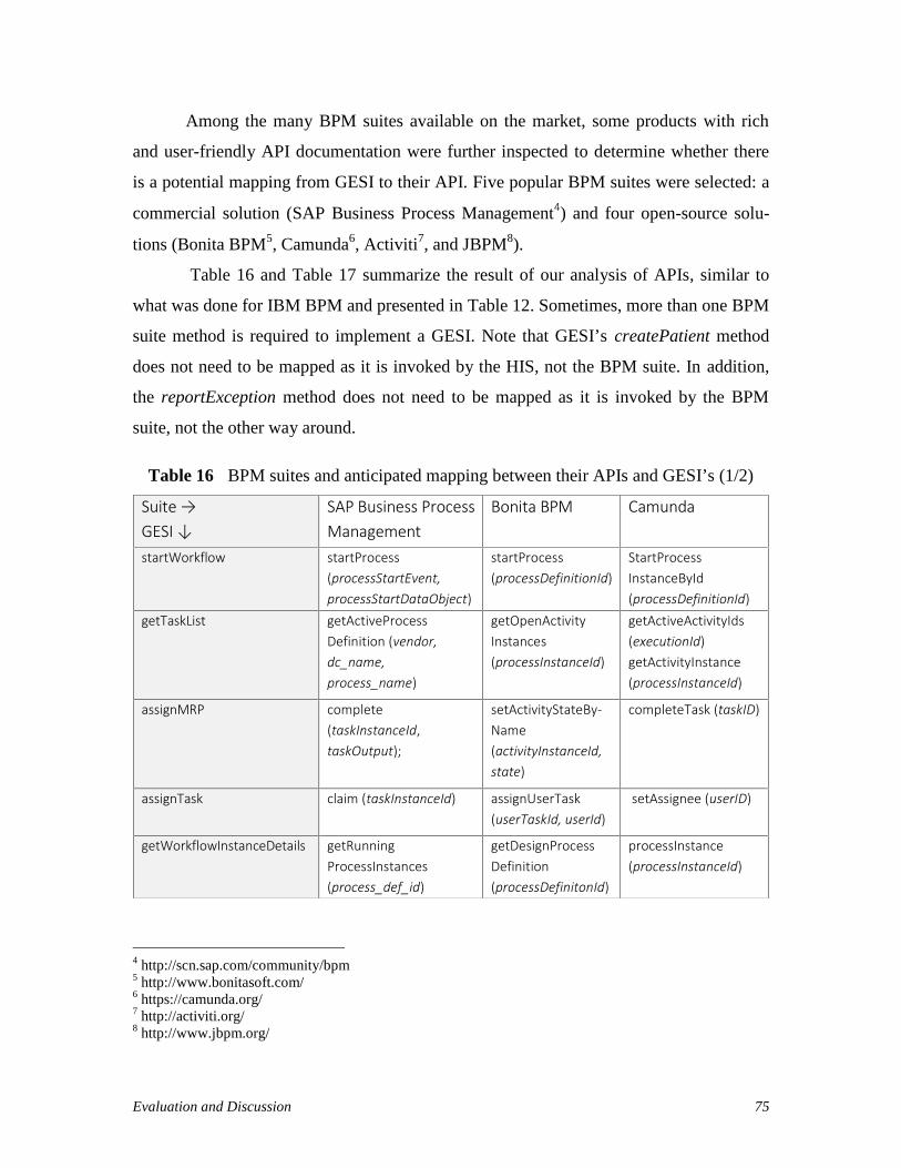
Evaluation and Discussion 75
Among the many BPM suites available on the market, some products with rich
and user-friendly API documentation were further inspected to determine whether there
is a potential mapping from GESI to their API. Five popular BPM suites were selected: a
commercial solution (SAP Business Process Management4) and four open-source solu-
tions (Bonita BPM5, Camunda6, Activiti7, and JBPM8).
Table 16 and Table 17 summarize the result of our analysis of APIs, similar to
what was done for IBM BPM and presented in Table 12. Sometimes, more than one BPM
suite method is required to implement a GESI. Note that GESI’s createPatient method
does not need to be mapped as it is invoked by the HIS, not the BPM suite. In addition,
the reportException method does not need to be mapped as it is invoked by the BPM
suite, not the other way around.
Table 16 BPM suites and anticipated mapping between their APIs and GESI’s (1/2)
4 http://scn.sap.com/community/bpm5 http://www.bonitasoft.com/6 https://camunda.org/7 http://activiti.org/8 http://www.jbpm.org/
Suite →GESI ↓
SAP Business ProcessManagement
Bonita BPM Camunda
startWorkflow startProcess(processStartEvent,processStartDataObject)
startProcess(processDefinitionId)
StartProcessInstanceById(processDefinitionId)
getTaskList getActiveProcessDefinition (vendor,dc_name,process_name)
getOpenActivityInstances(processInstanceId)
getActiveActivityIds(executionId)getActivityInstance(processInstanceId)
assignMRP complete(taskInstanceId,taskOutput);
setActivityStateBy-Name(activityInstanceId,state)
completeTask (taskID)
assignTask claim (taskInstanceId) assignUserTask(userTaskId, userId)
setAssignee (userID)
getWorkflowInstanceDetails getRunningProcessInstances(process_def_id)
getDesignProcessDefinition(processDefinitonId)
processInstance(processInstanceId)
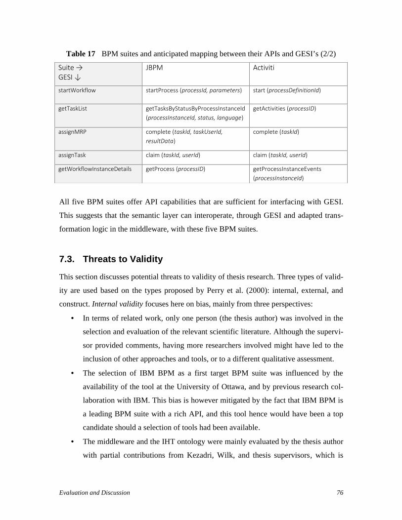
Evaluation and Discussion 76
Table 17 BPM suites and anticipated mapping between their APIs and GESI’s (2/2)
All five BPM suites offer API capabilities that are sufficient for interfacing with GESI.
This suggests that the semantic layer can interoperate, through GESI and adapted trans-
formation logic in the middleware, with these five BPM suites.
7.3. Threats to Validity
This section discusses potential threats to validity of thesis research. Three types of valid-
ity are used based on the types proposed by Perry et al. (2000): internal, external, and
construct. Internal validity focuses here on bias, mainly from three perspectives:
In terms of related work, only one person (the thesis author) was involved in the
selection and evaluation of the relevant scientific literature. Although the supervi-
sor provided comments, having more researchers involved might have led to the
inclusion of other approaches and tools, or to a different qualitative assessment.
The selection of IBM BPM as a first target BPM suite was influenced by the
availability of the tool at the University of Ottawa, and by previous research col-
laboration with IBM. This bias is however mitigated by the fact that IBM BPM is
a leading BPM suite with a rich API, and this tool hence would have been a top
candidate should a selection of tools had been available.
The middleware and the IHT ontology were mainly evaluated by the thesis author
with partial contributions from Kezadri, Wilk, and thesis supervisors, which is
Suite →GESI ↓
JBPM Activiti
startWorkflow startProcess (processId, parameters) start (processDefinitionId)
getTaskList getTasksByStatusByProcessInstanceId(processInstanceId, status, language)
getActivities (processID)
assignMRP complete (taskId, taskUserId,resultData)
complete (taskId)
assignTask claim (taskId, userId) claim (taskId, userId)
getWorkflowInstanceDetails getProcess (processID) getProcessInstanceEvents(processInstanceId)
Evaluation and Discussion 77
another source of potential bias. The nine goals defined for supporting IHT dy-
namics and used for the requirements and evaluation come from a number of
sources, including the literature. These goals were established and refined in col-
laboration with the thesis supervisors in order to mitigate bias. Demonstrations
were also given.
External validity focuses on the extent to which the results and contributions can be gen-
eralized:
One threat here is that the middleware was formally tested with only one BPM
suite. This was mitigated to some extent by an analysis of the APIs of five other
BPM suites, which points towards potential generalizability. This threat could be
further mitigated in the future by implementing middleware with other BPM
suites.
Another threat is related to the limited number of scenarios used in the validation
(two scenarios, coming from two simplified but realistic clinical workflows). Alt-
hough we covered the middleware requirements, the ontology concepts, as well as
major BPMN constructs, more extensive validation is needed to establish validity,
especially with regards to the semantic layer.
Currently, a patient is assumed to have only one presentation. Some patients how-
ever multi-morbidity (a number of concurrent conditions), and “merging” of the
workflows would be needed for managing these patients. This is left to future
work.
Construct validity focuses on the appropriateness and realism of the test measures for our
artefacts:
One threat is that the approach was not tested against a true hospital information
system (HIS). This is left for future work.
Another threat is related to a fact that several important issues, such as perfor-
mance, usability, robustness, security and privacy, have not been taken into con-
sideration in this research. The contribution is mainly limited to feasibility of de-

Evaluation and Discussion 78
veloping working middleware with GESI and does not represent an off-the-shelf
industrial-strength solution.
Last threat is that real processes, real practitioners, patients, and data from an op-
erational environment were not used to validate the effectiveness and efficiency
of this approach. To mitigate this threat, several online sources (The Ottawa Hos-
pital, 2008; NICE 2010) and advice from experts were used to create representa-
tive clinical workflows and scenarios.
7.4. Chapter Summary
This chapter argued, through a comparison with closely-related alternative approaches,
that the thesis approach currently provides a better overall satisfaction level of the nine
goals identified for the support of IHT dynamics. It addition, it also argued that the ap-
proach is not coupled to the specific BPM suite used in the implementation, and that the
middleware interface is likely compatible with many other commercial and open-source
BPM suites. Many internal, external, and construction threats were also identified togeth-
er with some mitigation strategies used in the thesis.
The next chapter gives overall conclusions about the thesis, including answers to
the research questions. It also presents future work items, many of which trying to further
mitigate remaining threats to validity discussed in this chapter.

Conclusions and Future Work 79
Chapter 8. Conclusions and Future Work
This chapter concludes by summarizing the contributions and answering the research
questions. Possible future work items are also identified.
8.1. Contributions
Considering the increased usage of BPM suites in a number of industries, healthcare does
not get all of the benefits it could from this platform. This study proposes an innovative
approach to support IHT dynamics while automating clinical workflows and getting addi-
tional benefits from a BPM suite. In addition, the tool-supported solution presented in
this thesis does not incur additional costs for hospitals, clinics or other healthcare provid-
ers that are already using BPM suites.
From a DSRM viewpoint, the thesis contributes concept and implementation arte-
facts (the minimal IHT Ontology and GESI, and the middleware implementation for IBM
BPM, respectively), but no method for their application is formally proposed. Several
iterations were performed in the identification of the needs, the creation of GESI, its im-
plementation, and the verification of the ontology’s minimality.
The first research question addressed in thesis was:
RQ1: What would a middleware between a semantic layer modeling team dynamics and
a feature-rich BPM engine be composed of?
The middleware enabled IHT management with a BPM suite consists of an interface and
transformation logic. Methods offered by BPM engines (presented in section 7.2) are
connected to a generic API (GESI, defined in Appendix A) offered by the middleware,
which then interacts with the semantic layer. The transformation logic handles the map-
ping of the methods and their data structures for successful interoperability between the

Conclusions and Future Work 80
semantic layer and the execution layer composed of the BPM engine and of the Hospital
Information System.
We believe that the middleware and GESI represent a step forward to support IHT
dynamics by integrating with BPM suites.
The second research question addressed in thesis was:
RQ2: What would a minimal ontology for capturing IHT concepts contain in order to be
independent from underlying workflow engines?
The IHT Ontology presented in Chapter 4 and used in semantic layer was shown to be
minimal against goals defined for the support of IHT dynamics.
8.2. Future Work
Although future work in this area is limitless, the first item involves increase of the con-
fidence level in the generality of the middleware. IBM BPM was selected as an execution
engine for this research study. However, the middleware is meant to be generic and
should be thoroughly tested with other BPM suites.
The middleware does not address exception handling in a comprehensive manner
(Goal 8), and improvements are needed in this area. The exceptions occurring in the BPM
suites need to be relayed to semantic layer. The semantic layer should take action based
on the exception type occurring in the BPM suite. The method reportException
(String exception) is included in GESI, however its implementation and whether it
is sufficient are issues left as a future work. In addition, the current GESI methods could
also generate exceptions catchable by the TWC component of the semantic layer.
Human factors, ethical issues, and operational issues were not taken into account
in this thesis. Similarly, many software engineering concerns such as privacy, security,
usability and performance should be better be analyzed and supported. Since the thesis is
limited to feasibility part, having solutions to these issues will help carry proposed ap-
proach to an industrial-strength environment.

Conclusions and Future Work 81
The integration with an HIS was only simulated. It can however be done with
standardized Health Level 7 (HL7) messages. Some additional data could be relayed
from the HIS to practitioner notification screens to let him/her better manage the patient.
Finally, although realistic, simplified clinical workflows were used as a proof of
concept, and it is clear that additional and more comprehensive workflows would lead to
a better validation. Such validation would also benefit from pilot implementation con-
ducted in real healthcare setting.

Conclusions and Future Work 82
References
Afrasiabi Rad, A., Benyoucef, M., and Kuziemsky, C. E. (2009). An evaluation frame-work for business process modeling languages in healthcare. Journal of theoreti-cal and applied electronic commerce research, 4(2), pp. 1-19.
Andreatta, P. B. (2010). A typology for health care teams. Health care management re-view, 35(4), pp. 345-354.
Astaraky, D., Wilk, S., Michalowski, W., Andreev, P., Kuziemsky, C., and Hadjiyanna-kis, S. (2013). A multiagent system to support an interdisciplinary healthcareteam: a case study of clinical obesity management in children. Proceedings of theVIII Workshop on Agents Applied in Health Care, Murcia, Spain, pp. 69-80.
Bertolini, C., Schäf, M., and Stolz, V. (2012). Towards a formal integrated model of col-laborative healthcare workflows. Foundations of Health Informatics Engineeringand Systems, LNCS 7151, Springer Berlin Heidelberg, pp. 57-74.
Bonitasoft (2015). Bonita BPM Documentation. Retrieved 28 July 2015, fromhttp://documentation.bonitasoft.com/
Borrill, C. S., Carletta, J., Carter, A., Dawson, J. F., Garrod, S., Rees, A., Richards A.,Shapiro D., and West, M. A. (2000). The effectiveness of health care teams in theNational Health Service. University of Aston in Birmingham, UK, pp. 14-30. Re-trieved 14 August 2015, from http://homepages.inf.ed.ac.uk/jeanc/DOH-final-report.pdf
Bpmgeek.com (2015). Integrating BonitaSoft using REST API's. Retrieved 28 July 2015,from http://bpmgeek.com/blog/integrating-bonitasoft-using-rest-apis
Brambilla, M. (2013). Application and simplification of BPM techniques for personalprocess management. Business Process Management Workshops, LNBIP 132,Springer Berlin Heidelberg, pp. 227-233.
Butt, L. and Caplan, B. (2010). The rehabilitation team. Handbook of Rehabilitation Psy-chology, 2nd ed. American Psychological Association, Washington, D.C., USA,pp. 451-457.
Cabanillas, C., Resinas, M., Mendling, J., and Ruiz-Cortés, A. (2015) Automated TeamSelection and Compliance Checking in Business Processes. 2015 InternationalConference on Software and System Process (ICSSP 2015), ACM, pp. 42-51.
Cain C., Haque S. (2008) Organizational Workflow and Its Impact on Work Quality. Pa-tient Safety and Quality: An Evidence-Based Handbook for Nurses. Agency forHealthcare Research and Quality (US); 31(1), Chapter 31.
Conclusions and Future Work 83
Camunda BPM docs (2015). BPMN 2.0 Implementation Reference. Retrieved 28 July2015, from http://docs.camunda.org/latest/api-references/bpmn20/
Craggs, S. (2009). Comparing BPM from IBM, Oracle and SAP. Lustratus Research.
Craggs, S. (2010). Comparing BPM from IBM, Software AG and Pegasystems. LustratusResearch.
Craggs, S. (2011). Comparing BPM from Pegasystems, IBM and TIBCO. Lustratus Re-search.
Dabaghkashani, A. Z., Hajiheydari, B. N., and Haghighinasab, C. M. (2011). A SuccessModel for Business Process Management Implementation. International Journalof Information and Electronics Engineering, 2(5), pp. 725-729.
Dang, J., Toklu, C., Hampel, K., and Enke, U. (2008). Human Workflows via Document-Driven Process Choreography, e-Technologies, 2008 International MCETECHConference, IEEE CS, pp. 25-33.
Demler. G., Pfau G., and O’Shea H. Modeling teams with IBM Process Designer, Re-trieved in 15 May 2015, from http://goo.gl/4XdDao.
Dwivedi, A., Bali, R. K., James, A. E., and Naguib, R. N. (2001). Workflow managementsystems: the healthcare technology of the future? Engineering in Medicine andBiology Society, 2001. Proceedings of the 23rd Annual International Conferenceof the IEEE, 4(23), pp. 3887-3890.
EICP (Enhancing Interdisciplinary Collaboration in Primary Health Care) (2005). Cana-dian Policy Context: Interdisciplinary Collaboration in Primary Health Care. Re-trieved 14 August 2015, from http://bit.ly/1Yc7DAv
Elmroth, E., Hernández, F., and Tordsson, J. (2008). A light-weight grid workflow exe-cution engine enabling client and middleware independence. Parallel Processingand Applied Mathematics, LNCS 4967, Springer Berlin, pp. 754-761.
Emanuele, J., and Koetter, L. (2007). Workflow opportunities and challenges inhealthcare. Siemens Medical Solutions USA, Inc., United States.
Eystein, M. and Krogstie, J. (2012). Modeling of Processes and Decisions in Healthcare-State of the Art and Research Directions. The Practice of Enterprise Modeling,LNBIP 134, Springer Berlin, Heidelberg, pp. 101-116.
Gang, N. (2008). A scheme of workflow management system based on web services.Electronic Commerce and Security, 2008 International Symposium, IEEE CS, pp.53-56.
Gatchel, R. J., McGeary, D. D., McGeary, C. A., and Lippe, B. (2014). Interdisciplinarychronic pain management: Past, present, and future. American Psychologist,69(2), pp. 119-130.
Gilbert, P. (2005). What is the difference between Workflow Engines and BPM Suites?Technical report, Lombardi Software.

Conclusions and Future Work 84
Gordon, R. M., Corcoran, J. R., Bartley-Daniele, P., Sklenar, D., Roach Sutton, P., andCartwright, F. (2014). A Transdisciplinary Team Approach to Pain Managementin Inpatient Health Care Settings. Pain Management Nursing, 15(1), pp. 426-435.
Grando, A., Peleg, M., and Glasspool, D. (2010). A goal-oriented framework for specify-ing clinical guidelines and handling medical errors. Journal of biomedical infor-matics, 43(2), pp. 287-299.
Grando, A., Peleg, M., Cuggia M., and Glasspool D. (2011). Patterns for collaborativework in health care teams. Artificial intelligence in medicine, 53(3), pp. 139-160.
Hall P, Weaver L. (2001). Interdisciplinary education and teamwork: a long and windingroad. Med Educ. 2001, 35(9), pp. 867–875.
Hepp, M., and Roman, D. (2007). An ontology framework for semantic business processmanagement. Wirtschaftinformatik Proceedings 2007, AISeL, pp. 27.
Hepp, M., Leymann, F., Domingue, J., Wahler, A., and Fensel, D. (2005). Semantic busi-ness process management: A vision towards using semantic web services forbusiness process management, e-Business Engineering, 2005. ICEBE 2005. IEEEInternational Conference, IEEE CS, pp. 535-540.
Hevner, A. R., March, S. T., Park, J., and Ram, S. (2004). Design Science in InformationSystems Research. MIS Quarterly, 28(1), pp.75-105.
Hill, J. B., Kerremans, M. (2007). Cool vendors in business process management, 2007.Gartner Research.
Hoogland, J. (2009). Change in control. Business Process Management, LNCS 5701,Springer-Verlag Berlin Heidelberg. pp. 28-30.
Hull, D., Wolstencroft, K., Stevens, R., Goble, C., Pocock, M. R., Li, P., and Oinn, T.(2006). Taverna: a tool for building and running workflows of services. Nucleicacids research, 34(2), pp. 729-732.
IBM (2012). The Ottawa Hospital Improves Patient Care and Safety (Case Study-USEN),Retrieved 11 August 2015, from http://ibm.co/1NBLvtw
IBM (2013). The Ottawa Hospital Puts Mobile Patients First (Case Study-USEN), Re-trieved 13 August 2015, from http://goo.gl/IUe98T
IBM (2015a). IBM Business Process Manager. Retrieved 28 July 2015, from http://www-03.ibm.com/software/products/en/business-process-manager-family
IBM (2015b). IBM developerWorks Technical Library Retrieved 8 June 2015, fromhttp://ibm.co/1LhxjII
IBM (2015c). IBM BPM REST APIs. IBM Knowledge Center. Retrieved 28 July 2015,from http://ibm.co/1MuPTfa
IBM (2015d). Handling Exceptions. IBM Business Monitor V8.5.5. IBM KnowledgeCenter. Retrieved 31 December 2015, from http://tinyurl.com/j4h6959

Conclusions and Future Work 85
Isern, D., Moreno, A., Sánchez, D., Hajnal, Á., Pedone, G., and Varga, L. Z. (2011).Agent-based execution of personalised home care treatments. Applied Intelli-gence, 34(2), pp. 155-180.
Jeston, J. and Nelis, J. (2014) Business Process Management: Practical Guidelines toSuccessful Implementations. Elsevier, pp. 3-4, pp. 29-31 and pp. 410-416.
Kamil, A. (2014). A comparison of different workflow modeling tools: Choosing the mostaccurate tool for designing a reliable healthcare system, eHealth Department.McMaster University. Hamilton, Canada. Doctoral dissertation, Retrieved 14 Au-gust 2015, from http://hdl.handle.net/11375/16091.
Kezadri-Hamiaz, M., Rosu, D., Wilk, S., Kuziemsky, C., Michalowski, W., and Carrier,M. (2015). A Framework for Modeling Workflow Execution by an Interdiscipli-nary Healthcare Team. Studies in health technology and informatics, 216, IOSPress, pp. 1100-1100.
Kitchenham, B. (2004). Procedures for performing systematic reviews. Keele UniversityTR/SE-0401 and NICTA 0400011T. 33(2004), Joint Technical Report. pp. 1-26.
Ko, R. (2009). A Computer Scientist’s Introductory Guide to Business Process Manage-ment (BPM). Crossroads, 15(4), ACM, pp. 11-18.
Kohn, L. T., Corrigan, J. M., and Donaldson, M. S. (2000). To err is human: building aSafer Health System. National Academy Press, Washington, D.C., pp. 30-33.
Kuziemsky, C., Astaraky, D., Wilk, S., Michalowski, W., and Andreev, P. (2014). AFramework for Incorporating Patient Preferences to Deliver ParticipatoryMedicine via Interdisciplinary Healthcare Teams. AMIA Annual SymposiumProceedings, Washington, USA, pp. 835-844.
Lenz, R., and Kuhn, K. A. (2004). Towards a continuous evolution and adaptation ofinformation systems in healthcare. International journal of medical informatics,73(1), pp.75-89.
Lenz, R., Peleg, M., and Reichert, M. (2012). Healthcare process support: achievements,challenges, current research. International Journal of Knowledge-BasedOrganizations (IJKBO), 2(4).
Lillehagen, F., and Krogstie, J. (2008). Approaches to Enterprise Solutions. ActiveKnowledge Modeling of Enterprises, Chapter 6, Springer, pp. 153-192.
Lopez-Sanchez, M., Miralles, J. C., and Musavi, A. (2009). Approaches to HospitalProcess Management. Artificial Intelligence Research and Development, IOSPress, pp. 409-418.
Mackey, H., and Nancarrow, S. (2005). Assistant practitioners: issues of accountability,delegation and competence. International Journal of Therapy and Rehabilitation,12(8), pp. 331-337.
Malik, T. S. (2009). Process Management: Practical Guidelines to Successful Implemen-tation. Global India Publications PVT Ltd, pp. 40-44.

Conclusions and Future Work 86
Mathisen, E., and Krogstie, J. (2012). Modeling of Processes and Decisions inHealthcare-State of the Art and Research Directions. The Practice of EnterpriseModeling, LNBIP 134, Springer Berlin Heidelberg, pp. 101-116.
McAdam, R., Keogh, W., Galbraith, B., and Laurie, D. (2005). Defining and improvingtechnology transfer business and management processes in university innovationcentres. Technovation, 25(12). Elsevier, pp. 1418-1429.
Mendling J., Recker J. C., and Wolf J. (2012). Collaboration features in current BPMtools. EMISA Forum, 32(1), pp. 48-65.
Michalowski, M., Wilk, S., Michalowski, W., Tan, X., and Rosu, D. (2014). Using first-‐order logic to represent clinical practice guidelines and to mitigate adverse inter-actions. KR4HC 2014, LNAI 8903, Springer Switzerland, pp. 45-61.
Microsoft Research (2015). Z3 Prover. Retrieved 21 December 2015 fromhttps://github.com/Z3Prover/z3
NICE (2008). Stroke and transient ischaemic attack in over 16s: diagnosis and initialmanagement. Guidelines CG68, UK National Institute for Health and Care Excel-lence. Retrieved 21 December 2015 from https://www.nice.org.uk/guidance/cg68
Nolte, J., and Tremblay, M. (2005). Enhancing Interdisciplinary Collaboration in Prima-ry Health Care in Canada. The Conference Board of Canada. Retrieved 14 Au-gust 2015, from http://bit.ly/1PJ9Tw4
Oandasan, I., D’Amour, D., Zwarenstein, M., Barker, K., Purden, M., Beaulieu, M. D.,Reeves, S., and Tregunno, D. (2004). Interdisciplinary education for collabora-tive, patient-centred practice: research and findings report. Health Canada, pp.41-99.
OASIS (2007). Web Services Business Process Execution Language Version 2.0. OASISStandard, 11 April 2007.
OMG (2011). Business Process Model and Notation (BPMN), Version 2.0. Standard for-mal/2011-01-03, January 2011.
Panagacos, T. (2012). The Ultimate Guide to Business Process Management: Everythingyou need to know and how to apply it to your organization. CreateSpace Publish-ing, pp. 12-24.
Papapanagiotou, P., and Fleuriot, J. D. (2014). Formal verification of collaboration pat-terns in healthcare. Behaviour & Information Technology, 33(12), pp. 1278-1293.
Papapanagiotou, P., Fleuriot, J., and Grando, A. (2012). Rigorous process-based model-ling of patterns for collaborative work in healthcare teams. 2012 25th IEEE Int.Symposium on Computer-Based Medical Systems (CBMS). IEEE CS, pp. 1-6.
Pourshahid, A. (2014). A Framework for Monitoring and Adapting Business ProcessesUsing Aspect-Oriented URN. Doctoral dissertation, Computer Science, Universityof Ottawa, Canada.

Conclusions and Future Work 87
Pourshahid, A., Amyot, D., Peyton, L., Ghanavati, S., Chen, P., Weiss, M., and Forster,A. J. (2009). Business process management with the User Requirements Notation.Electronic Commerce Research, 9(4), pp. 269-316.
Prater, J., Mueller, R., and Beauregard, B. (2012). An ontological approach to OracleBPM. The Semantic Web, LNCS 7185, Springer Berlin Heidelberg, pp. 402-410.
Prinyapol, N., Fan, J. P., and Lau, S. (2009). A hospital based dynamic platform work-flow management. IAENG International Journal of Computer Science, 36(2), pp.192-198
Prinyapol, N., Lau, S. K., and Fan, J. P. O. (2010). A dynamic nursing workflow man-agement system: A Thailand hospital scenario. Intelligent Automation and Com-puter Engineering, LNEE 52, Springer Netherland, pp. 489-501.
Reichert, M. (2011). What BPM technology can do for healthcare process support? Arti-ficial Intelligence in Medicine, LNCS 6747, Springer Berlin, Heidelberg, pp. 2-13.
Rowland, P. (2014). Core principles and values of effective team-based health care.Journal of Interprofessional Care, 28(1), pp. 79-80.
Ruan, J., MacCaull, W., and Jewers, H. (2012). Agent-Based Careflow for Patient-Centred Palliative Care. Electronic Healthcare, LNICST 69, Springer Berlin Hei-delberg, pp. 285-294.
Russell, N., Ter Hofstede, A. H., and Mulyar, N. (2006). Workflow control flow patterns:A revised view. Tech. Rep. BPM-06-22, BPM center.org.
SAP (2015) Working with the BPM APIs - Modeling Processes with Process Composer -SAP Library. Retrieved 13 August 2015, from http://bit.ly/1DYiN6m
Sinur, J., and Hill, J. B. (2010). Magic quadrant for business process management suites.Gartner RAS Core research note, GARTNER, pp 1-24.
Schael, T. (1998). Workflow management systems for process organisations. LNCS1096, Springer-Verlag, pp. 83-84.
Schmidt, A., and Kunzmann, C. (2006). Towards a human resource development ontolo-gy for combining competence management and technology-enhanced workplacelearning. On the Move to Meaningful Internet Systems 2006: OTM 2006 Work-shops, LNCS 4278, Springer Berlin Heidelberg, pp. 1078-1087.
Taplin, Stephen H., Mary K. Foster, and Stephen M. Shortell (2013). Organizationalleadership for building effective health care teams. Annals of Family Medicine,11(3), pp. 279-281
Tchemeube, R. B. (2013). Location-Aware Business Process Management for Real-timeMonitoring of Patient Care Processes. Master’s thesis, Computer Science, Univer-sity of Ottawa, Canada.
The Ottawa Hospital (2010). Radical Prostatectomy Surgery. Rev 09/2010. Retrieved 21December 2015 from http://bit.ly/20tljbo

Conclusions and Future Work 88
van der Aalst, W. M. P. (1998). The application of Petri nets to workflow management.Journal of circuits, systems, and computers, 8(1), pp. 21-66.
van der Aalst W. M. P. (2004). Business Process Management in Healthcare, Closing theloop by mining careflows. Invited talk at Medinfo 2004, MIT press, San Francis-co, USA.
van der Aalst, W. M. P., Ter Hofstede, A. H., and Weske, M. (2003). Business processmanagement: A survey. Business process management, LNCS 2678, SpringerBerlin, Heidelberg, pp. 1-12.
Verna, J., Petersen, S., Samis, S., Akynov, N., and Graham, J. (2014). Healthcare Priori-ties in Canada: A Backgrounder. Canadian Foundation for Healthcare Improve-ment. Retrieved 17 August 2015, from http://bit.ly/1UPME4K.
Vom Brocke, J., and Rosemann, M. (Eds.) (2010). Handbook on business process man-agement 1. Springer Verlag Berlin Heidelberg, pp. 12-15 and pp. 417-419.
Watson, D., Wong, S. (2005). Canadian Policy Context: Interdisciplinary Collaborationin Primary Health Care. The Conference Board of Canada, pp. 11-12. Retrieved17 August 2015, from http://bit.ly/1Yc7DAv
Westergaard, M. (2011). Access/CPN 2.0: a high-level interface to coloured petri netmodels. Applications and Theory of Petri Nets, LNCS 6709, Springer Berlin,Heidelberg, pp. 328-337.
Westergaard, M., and Slaats, T. (2013). CPN Tools 4: A process modeling tool combin-ing declarative and imperative paradigms. Automatic Control and Computer Sci-ences, 47(7), pp. 393-402.
WFMC (1996) Workflow management coalition terminology and glossary (WFMC-TC-1011). Workflow Management Coalition. Retrieved 20 October 2015 fromhttp://tinyurl.com/qz2bghf
Wilk, S., Astaraky, D., Michalowski, W., Amyot, D., Li, R., Kuziemsky, C., and An-dreev, P. (2014a). MET4: Supporting Workflow Execution for InterdisciplinaryHealthcare Teams. Business Process Management Workshops, LNBIP 202,Springer International Publishing, pp. 40-52.
Wilk, S., Michalowski, M., Tan, X., and Michalowski, W. (2014b). Using First-OrderLogic to Represent Clinical Practice Guidelines and to Mitigate Adverse Interac-tions. Knowledge Representation for Health Care, Springer International Publish-ing. 8903, pp. 45-61.
Wilk, S., Kezadri-Hamiaz, M., Rosu, D., Kuziemsky, C., Michalowski, W., Amyot, D.,and Carrier M. (2016). Using Semantic Components to Represent Dynamics of anInterdisciplinary Healthcare Team in a Multi-agent Decision Support System.Journal of Medical Systems, 40:42, Springer, February 2016, pp. 1-12.
Ye, Y., Jiang, Z., Yang, D., and Du, G. (2008). A semantics-based clinical pathwayworkflow and variance management framework. Service Operations and Logis-tics, and Informatics, 2008 (IEEE/SOLI 2008). IEEE International Conference,IEEE CS, pp. 758-763.

Conclusions and Future Work 89
Zur Muehlen, M. (2004). Workflow-based process controlling: foundation, design, andapplication of workflow-driven process information systems. Logos Verlag Ber-lin, 2004, pp. 92-98.

Appendix A: Generic Engine and Semantic Interface (GESI) 90
Appendix A: Generic Engine and SemanticInterface (GESI)
A JavaDoc version of the middleware package (including GESI) is available online at
http://www.site.uottawa.ca/~damyot/pub/GESI/
package middleware;
import java.util.ArrayList;
/*** Generic Engine and Semantics Interface (GESI)* Enables the interoperability between the Team and Workflow* Controller (TWC) component of a semantic layer and an underlying* business process management (BPM) suite to which we want to* add support for Interdisciplinary Healthcare Team (IHT) dynamics.** @author Nihan Catal <[email protected]>* @version 1.0* @since 2016-01-28*/
public interface GESI {
/*** Creates a new patient in TWC with the given parameters.* Invoked by the healthcare information system (HIS) in the* execution layer.** @param patientName Name of patient* @param presentation Presentation (disease) of the patient*/
public abstract void createPatient(String patientName, String presentation);
/*** Starts a workflow instance the BPM suite with the given parameters.* Invoked by the TWC in the semantic layer.** @param name Name of patient registered by the HIS* @param workflowID Identifier of the workflow defined in the BPM suite* @return Workflow instance identifier created by the BPM suite*/
public abstract String startWorkflow(String name, WorkflowID workflowID);

Appendix A: Generic Engine and Semantic Interface (GESI) 91
/*** Gets the list of tasks information objects given a task status* used as a filter. Task info contains task id, task type, workflow* type, task status, and the assignee of the task. t_New_MRP is a* task type requiring the assignment of a new leader.* Invoked by the TWC in the semantic layer.** @param taskStatus Task task used as filter* @return Task list with information*/
public abstract ArrayList<TaskInfo> getTaskList(String taskStatus);
/*** Assigns the selected leader, Most Responsible Practitioner (MRP)* to the selected workflow or sub-workflow, and closes the* t_New_MRP task.* Invoked by the TWC in the semantic layer.** @param newMRP Selected MRP for the running sub-workflow* @param task_ID Task instance to be closed.*/
public abstract void assignMRP(String newMRP, String task_ID);
/*** Commands the BPM suite to assign the practitioner to the task.* Invoked by the TWC in the semantic layer.** @param task_ID Task instance assigned to the practitioner* @param practitioner Practitioner assigned to the task instance*/
public abstract void assignTask(String task_ID, String practitioner);
/*** Gets the workflow instance details as a list of tasks.* Invoked by the TWC in the semantic layer.** @param processID Workflow instance in the BPM suite* @return taskList Task list with information*/
public abstract ArrayList<TaskInfo> getWorkflowInstanceDetails(StringprocessID);
/*** Relays exceptions unhandled by the BPM suite to the semantic layer.* Invoked by the BPM suite in the execution layer** @param exception Relayed exception*/
public abstract void reportException(String exception);
}

Appendix B: Clinical Workflows 92
Appendix B: Clinical Workflows
Figure 22 and Figure 23 are process models of two clinical workflows.
assessments_treatments
i_or_day
c_anesthesia (2) c_ surgery (3)
t_anesthesia t_surgery
s_surgery (2)
i_day_1
i_day_2
i_day_3
t_patient_specific_medications
t_IV_heparin1
t_instrumentation
i_day_4
t_surgery_assistance
i_assessments_treatments
t_activity
i_medication
t_pain_management_medication
t_JP_discharge_assessment
t_systems_assessments
t_wound_monitoring
t_IV_heparin2
i_assessments_treatments
t_activity
i_medication
t_discharge_instructions
T_nutrition
t_tests
Start eventEnd event
Parallel gateway
Decision gateway
Normal task
Required specialty
Sub-workflow invocation
Required capability (competency level)
s_surgery (2)
c_specific_medications (1)
c_IV heparin (2)
s_surgery (1)
c_instrumentation (1) c_surgery_assistance (3)
s_surgery (1)
c_activity (2)
c_pain_management_medication (1)
c_JP_assessment (1)
c_systems_assessments (2)
s_surgery (1)
c_wound_monitoring (1)
c_IV heparin (2)
s_surgery (1)
c_activity (2)
c_teaching (2)
c_nutrition (2)
c_tests (2)
Figure 22 Simplified radical prostatectomy workflow

Appendix B: Clinical Workflows 93
These workflows are used to support the proof-of-concept scenarios that illustrate the
feasibility and capabilities of the system, including its new middleware layer. The first
one (Figure 22) is a simplified radical prostatectomy, which concerns management of a
patient who needs surgical removal of all or part of the prostate gland. The steps of this 5-
day process (from day 0 to day 4) are used to structure the tasks, and the diagram focuses
on the first three days (in-patient management). Several activities are refined into sub-
processes. The model is derived from existing clinical pathway at The Ottawa Hospital
(2010), but is augmented with requirements in terms of specialities (e.g., surgery at levels
1 or 2), and capabilities (e.g., anaesthesia and intravenous (IV) heparin at level 2).
The second clinical workflow (Figure 23) targets acute stroke management and is
derived from UK guideline (NICE, 2008). While Figure 22 covered sequential and paral-
lel tasks as well as sub-processes, the model in Figure 23 also covers alternative tasks and
urgent tasks.
Yes
t_Brain_CT_scan
t_Incranial_hemorrhage_evaluation
t_ imaging_evaluation
t_GCS_assessment
t_Stroke_unit_admission
No
No
t_Thrombolysis_with_alteplaseYes
t_MUST_test t_Early_mobilization
t_Diagnostic_brain_CT_scan
t_Maintenance_therapy
t_Pharmacologial_therapy
Start eventEnd event
Parallel gateway
Decision gateway
Normal task
Required specialty
Sub-workflow invocation
Required capability(competency level)
Task collection
Imagingneeded?
Hemorrhageexcluded?
Urgent task
c_assess_GCS (1)
c_assess_imaging_need(2)
c_perform_CT (2)
c_evaluate_CT (3)
c_provide_IV_treatment (2)
c_mobil ize_pat ient (2)
c_implement_pharmacological_therapy (1)
c_perform_CT (2)
c_implement_maitenance_therapy (1)
c_perform_MUST_test (2)
s_cardiology (2)
Figure 23 Simplified acute stroke management workflow