suppression of the aeroelastic/aeroservoelastic interaction using … · 2017. 3. 16. · aaw...
TRANSCRIPT

Suppression of the Aeroelastic/Aeroservoelastic InteractionUsing Adaptive Feedback Control Instead of Notching Filters
Jie Zeng∗
and Jiang Wang†
ZONA Technology Inc, Scottsdale, Arizona, 85258, U.S.A
Raymond de Callafon‡
University of California, San Diego, La Jolla, California,92093, U.S.A
Martin Brenner§
NASA Dryden Flight Research Center, Edwards, California, 93523, U.S.A
This paper investigates the possibility that an adaptive feedback controller can be designed and imple-mented for the suppression of aircraft’s structural vibrat ion in the presence of any aeroelastic/aeroservoelasticinteraction, instead of using the non-adaptive notching filters. Currently aircraft with non-adaptive controllaws usually include roll-off or notch filters to avoid AE/ASE interactions. However, if changes in the air-craft configuration are significant, the frequencies of the flexible modes of the aircraft may be shifted and thenotch filters could become totally ineffective. With the proposed adaptive feedback control technology, theflexible dynamics can be consistently estimated via system identification algorithms and its undesirable effectsare suppressed through a robust feedback control law, whilethe whole systems stability is being maintained.The proposed feedback control technique is demonstrated with a 6-DOF nonlinear F/A-18 AAW model for thesuppression of the aeroelastic/aeroservoelastic interaction.
I. Introduction
To date, because of the slender, more flexible, and/or sizable design of the next generation aircraft such as Morph-ing UAVs, HALEs, Oblique Flying Wings, sensorcrafts, etc.,where there is insufficient frequency separation betweenthe rigid body dynamics and relatively low frequency aeroelastic/aeroservoelastic modes, flight control laws based onthe 6 d.o.f. rigid body model may result in unacceptable stability margins or undesirable response characteristics duetocontrol input or turbulence. Therefore, to maintain good flying qualities of an aircraft, the aeroelastic/aeroservoelasticmodes interaction to the rigid body dynamics has to be minimized using appropriate methods.
The usual way to suppress the effects of the low frequency aeroelastic/aeroservoelastic modes on the rigid bodydynamics was performed through the notch filter design technique. However, if changes in the aircraft configurationare significant, the frequencies of the flexible modes of the aircraft may be shifted and the notch filters could becometotally ineffective.
In this paper an indirect adaptive control algorithm is introduced to suppress the aeroelastic/aeroservoelastic modesinteraction. With this algorithm, poorly damped structural resonance modes induced by aero(servo)elastic interactioncan be monitored and modelled via system identification techniques. Such estimation techniques can use time-domainmeasurements of input/output behavior to formulate a dynamical model suitable for control system design for vibrationsuppression. With the availability of a model, a model-based feedback control design methodology can be used todampen the resonance modes, and therefore reduce the the effects of the aeroelastic/aeroservoelastic modes on rigid
∗R & D Control System Engineer, Member AIAA. [email protected]†Member AIAA. [email protected]‡Associate Professor. [email protected]§Aerospace Engineer, Member AIAA. [email protected]
1 of 20
American Institute of Aeronautics and Astronautics

body dynamics. The performance of the notch filters and the proposed adaptive control algorithm are compared andvalidated with the use of the nonlinear F/A-18 AAW model integrated with the NASA AAW flight research controller.
II. Adaptive Control Algorithm
The adaptive control algorithm implemented in this paper includes two part: aeroelastic/aeroservoelastic modelapproximation using system identification techniques and robust controller design based on the estimated aeroelas-tic/aeroservoelastic model for the suppression of the aeroelastic/aeroservoelastic interaction.
Aeroelastic/Aeroservoelastic Model Approximation
Consider a linear, time-invariant, discrete-time system
y(t) =
∞∑
k=0
G(k)u(t − k) + v(t). (1)
The system Markov parameters,G(k) ∈ Rny×nu define the relationship between the input signal,u(t) ∈ R
nu , andthe output signal,y(t) ∈ R
ny , which contains an additive noise signal,v(t) ∈ Rny . We assume that the input and
output signals are quasi-stationary and that the noise,v(t), is stationary.Such a system has an infinite number of state-space representations of the form
x(t + 1) = Ax(t) + Bu(t)
y(t) = Cx(t) + Du(t) + v(t)(2)
given in terms of constant matricesA ∈ Rn×n, B ∈ R
n×nu , C ∈ Rny×n, andD ∈ R
ny×nu . The state-space matricesare related to the system Markov parameters byG(k) = CAk−1B for k > 0 andG(0) = D. We assume that allstate-space representations are controllable and observable, and that they are minimal, that is the dimension of thestate equal to the system ordern. The identification problem considered is to estimate (i) the system ordern and (ii)state-space matricesA, B, C, andD from measured data generated by the above system. The problem of estimatinga realization of the process that generatesv(t) is not addressed. With the input signalu(t) and output signaly(t)available, a time domain Subspace identification method1 or step based system identification method2 can be directlyapplied for the estimation of the system matricesA, B, C, andD.
H∞ Loop Shaping Controller Design Method
TheH∞ loop shaping controller design method was developed by Glover and McFarlane.3 This method is favor-able as it formulates the control design problem as a standard 4-block problem for which an explicit solution existsbased on a Nehari-extension. The computation of the controller does not require an iteration and solutions are formu-lated in the form of a Hankel-norm based model reduction for which standard Algebraic Ricatti equations need to besolved. TheH∞ loop shaping control design formulation is illustrated in Figure 1.
W(q)
y(t)r(t)
Figure 1. H∞ Loop Shaping Control Design Formulation.
Essential to the automatic updating of the controller is theuse of a loop shaping in the controller design method-ology that allows the computation of controllersCpert(q) that are, by themselves, also stable. The loop shaping canbe user specified or scaled by a scalar variable for automaticscaling selection to obtain a stable, stabilizing feedbackcontroller. The scaling serves as anH∞ loop shaping in the computation of the optimal controller asfollows.
1. Define a weighted closed-loop model,Gα(q), given by
Gα(q) = αW (q)G(q)
2 of 20
American Institute of Aeronautics and Astronautics

whereα is a variable gain andW (q) is a fixed filter that can be used to specify high frequency roll-off or otherdesirable properties for the to-be computed controllerCpert(q). G(q) is the identified model which models thetransient behavior of the resonance of the structure.
2. Solve the (weighted) 4-blockH∞ optimization problem
Cα = minC
‖T (Gα, C)‖∞, T (Gα, C) =
[
Gα
I
]
(I + CGα)−1
[
I C
]
The optimization is guaranteed to find a controller,Cα, that forms a stable feedback connection withGα.
3. Check if the controllerCα(q) by itself is also stable. If not, reduce the value ofα and go back to Item 1.
4. If the controllerCα(q) by itself is also stable, then computeCpert via
Cpert(q) = αW (q)Cα(q)
The resulting controllerCpert(q) will (internally) stabilizeG(q) and is by itself also stable. Stability ofCpert(q)facilitates the on-line implementation of the controller as an additive perturbation to the original flight controller.
It should be noted that theH∞ loop shaping controller design does not have the capabilityto explicitly deal withthe structure vibrations due to the external unmeasurable perturbation such as gust perturbation.
III. Effects of the Notch Filters on the Reduction of the Aeroelastic/AeroservoelasticModes Interaction
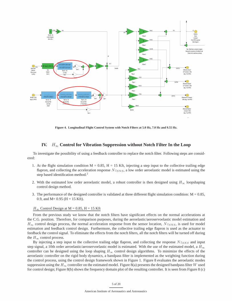
In order to evaluate the effects of the notch filters on the suppression of the aeroelastic/aeroservoelastic modes inter-action, and also investigate the feasibility of theH∞ Controller replacing the noth filters for aeroelastic/aeroservoelasticvibration suppression, the NASA active aeroelastic wing (AAW) flight control system has been integrated into the cur-rent Nonlinear F/A-18 AAW simulink model. The integrated F/A-18 AAW model is illustrated in Figure 2. The NASAAAW flight control system in Figure 2 is marked by a red coloredellipse. One notch filter located at 9.55 Hz wasadded to the longitudinal control system, see Figure 3; and three additional notch filters located at 5 Hz, 7 Hz and17 Hz were added to the lateral control system, see Figure 4. In the following sections, the integrated F/A-18 AAWclosed loop linear model will be implemented to analyze the effects of the notch filters andH∞ aeroelastic control onthe aeroelastic/aeroservoelastic modes suppression.
The effects of the notch filters can be validated by turning on/off the notch filters in the longitudinal and lat-eral control system. In this study, only the longitudinal dynamics were focused on during the study of the aeroeal-stic/aeroservoelastic interaction. At flight condition M =0.85, H = 15 Kft, injecting a doublet command to the lon-gitudinal stick, by turning on/off the notch filters, the simulation results can be compared and further illustrated inFigures 5, 6, and 7. From the deflection of the control surfaces in Figure 7, normal acceleration responses at theC.G. position in Figure 6 (a) and (b), and pitch rate responsein Figure 5(d), it is easily observed that with the useof the notch filter in the flight control system the aeroelastic/aeroservoelastic modes interaction can be successfullysuppressed. However, from Figure 6 (a) and (b) it is clearly seen that the notch filters have no effects on the highfrequency oscillation reduction of the normal acceleration response at left/right wing folder position,Nzkm023L andNzkm023R. By further investigation it was found that the normal acceleration responses at the left/right wing folderposition,Nzkm023L andNzkm023R, were dominated by two elastic modes located at 6 Hz and 16.3 Hz, respectively.However, other high frequency responses such asNzPlt andNzSNS are dominated by an elastic mode around 9.5Hz. That is the reason why with a notch filter at 9.55 Hz, the high frequency responses at the longitudinal directioncan be successfully suppressed.
It is well known that using the notch filters in the control paths to suppress the presence of any undesired elasticmodes is a standard automatic control practice in the aerospace industry. However, if changes in the aircraft configu-ration are significant, due to any abrupt operating conditions change, such as an unexpected massive store separationand/combat related structural damage, the frequencies of the flexible modes of the aircraft may be shifted and thenotch filters could become totally ineffective. Under such circumstances, an adaptive control scheme through iter-atively on-line estimating the aeroelastic/aeroservoelastic dynamics and design of theH∞ aeroelastic controller foraeroelastic/aeroservoelastic modes interaction suppression will overcome the issues arising from the usage of the notchfilters. In the following section, instead of using notch filters, aH∞ aeroelastic controller is designed based on themodel estimated using the system identification techniques, and its performance will be evaluated.
3 of 20
American Institute of Aeronautics and Astronautics

Lat
Long
ZONA TECHNOLOGY INC.
PROPRIETARY
gust path
Plot the System Response
of the Last Run Simulation
Save Data
of the Last Run SimulationPerform CL System ID
based on Saved Data
Plot the System Responses
of Saved Data
Close All
Figures Design of Hinf Loopshape/Mixed Sensitivity Controller
Cpert based on Identified Models
F/A-18 AAW Nonlinear Model
2
Generic Longitudinal
Output
1
Generic Lateral
Output
white_noise gust
gust fi lter
error_Nz
reference3
error_Nz1
reference
T
Scope2
In1
In2
lat_stk_cmmd
pedal_cmmd
lon_stk_cmmd
Reference Signals1
Lat
lat_stk
pedal_cmmd
lon_cmmd
Lon
Lat_stk
Lat_Ctrl
Lon_Ctrl
Lon_stk
NASA AAW Flight Research ControllerIn
Out
Out1
Meaurment 1
1
Gain7
-K-
Gain5
-K-
Gain4 150
1
-K-
Gain
lat_stk_cmmd
Lat_dy n
Lon_dy n
Surf Def lection
lon_stk_cmmd
Lateral Output
Lonitudinal Output
Flight variables
Visualization
F18 6dof_Rigid Body Dynamics
x' = Ax+Bu
y = Cx+DuCpert
Clock
Chirp Signal1
2
Generic Longitudinal
Input
1
Generic Lateral
Input
15
15
15
5
5
3
3
15
15
15
15
12
15{15}
15{15}
15{15}
2
5
Figure 2. Integration of the NASA Flight Control System into F/A-18 AAW Nonlinear Model.
Collective Stabilator
Command 80Hz
(deg ), From RFCS
Collective Aileron
Command
(To RFCS Lateral Axis
Block Diagram )
Stick
Gradient (lbs/in )
PK1*abs(u[1]) +PK2)*u[1]
Pitch Stick (lbs),
to Integrator
Pitch Stick
(lbs)
(From P 80A)
Pitch Rate
(deg /s)
(From P 80A)
Pitch Rate
(deg /s)
V4]
Pitch Integrator
and Outer Loop
Command
PV1 = 0
for AOAS<22
(Linearized Block Diagram )
Normal Acceleration
Error, G's
NZGear 6
NZGear 4
NZ (G's)
to Integrator
NZ
(G's)
(From P 40A)
PK29
.0/382 ^2
Gain 2
Gain
Filter No . P9
Limited
Forward Loop
Integrator
+25
-50
Filter No . P8
Structural Filter
(9.55 Hz Notch )
s+3600
s+3600
Filter No . P7
Limited
Trim Integrator
(Notes 4 & 42)
(Set Constant )
Filter No . P5
25 rad/sec
Lag Filter
(PK45, PK46)
04s+1
Filter No . P2
Lead -Lag
(PK11, PK12)
.015 *(1+F22)s+1
.015 s+1
Filter No . P15
Speedbrake
Compensation
(Set Constant )
Angle of Attack
(deg )
To Integrator
Angle of Attack
(deg )
(From P 40B)
(Note 46 )
8*PK24
Yaw Rate 40Hz
(deg /s), to RFCS
Roll Rate 80Hz
(deg /s), to RFCS
Normal Acceleration
40Hz (G's), to RFCS
Pitch Rate 80Hz
(deg /s), to RFCS
2
Longitudinal Stick
Deflection 80Hz
(Inches), to RFCS
1stabc1
ciopci1
pv partial
tio
A2
rcolstb
KNzerr
KNzerr
PV6
Nz
anz1
deg/s
deg/s
Y
YCSLO
Figure 3. Longitudinal Flight Control System with Notch Fil ter at 9.55 Hz.
4 of 20
American Institute of Aeronautics and Astronautics
Note : Right Aileron command is negative ,
following the conventions of the MatrixX code .
Position limit is switched accordingly .
rs9
ailc 1
PcmdErr
Differential TEF Command
80Hz (deg ), From RFCS
Differential Outboard
LEF Command 80Hz
(deg ), From RFCS
Differential Inboard
LEF Command 80Hz
(deg ), From RFCS
Stick
Gradient
(lbs/in )
(RK1*abs(u[1]) +RK2)*u[1] PGF5
PdGear 4
G4
PdGear 3
G3
PdGear 2
G2
PdGear 1
G1
PGear 4
L
PGear 3
EF
PGear 2
FO
PGear 1
FI
Gain 5
Gain 3
Gain 2
Gain 1
K5
Filter No . R5
Limited Integrator
(Set to Zero )
0
Filter No . R4
Structural Filter
(17 Hertz Notch )
(1/107 ) 2s +2 (.03 /107 )s+1
(1/107 )^2s +2*(.7/107 )s+12
Filter No . R3
Structural Filter
(7.0 Hertz Notch )
(1/44.0) 2s +2 (.07/44 .0)s+1
(1/44.0)^2s +2*(.7/44 .0)s+12
Filter No . R2
5.0 Hertz
Notch
(1/31.4)^2s +2*(.05/31 .4)s+12
(1/31.4)^2s +2*(.5/31 .4)s+12
Filter No . R1
Structural Filter
2nd-Order
Rolloff
1
(1/90 )^2s +2*(.8/90 )s+12
Collective
Aileron
Command
(From RFCS Long Axis
Block Diagram )
Roll Rate 80Hz
(deg /s), to RFCS
Lateral Stick
Deflection
80Hz (Inches)
To RFCS
1
pfb1b
dlat4
A2RV3PdAILC
PAILC
PdLEIC
DLEFCS
PLEIC
PdLEOC
PLEOC
DLEFDO
PdTEIC
DTEFCS
PTEIC
SBRAC1
pfb3
Y
RV9
CSLA
LRTRIS
Note : Right Aileron command is negative ,
following the conventions of the MatrixX code .
Position limit is switched accordingly .
rs9
ailc 1
PcmdErr
Differential Stabilator
Command 80Hz
(deg ), From RFCS
Differential TEF Command
80Hz (deg ), From RFCS
Differential Outboard
LEF Command 80Hz
(deg ), From RFCS
Differential Inboard
LEF Command 80Hz
(deg ), From RFCS
Stick
Gradient
(lbs/in )
(RK1*abs(u[1]) +RK2)*u[1]
RKSTAB
PGF5
PdGear 4
G4
PdGear 3
G3
PdGear 2
G2
PdGear 1
G1
PGear 4
L
PGear 3
EF
PGear 2
FO
PGear 1
FI
Gain 5
Gain 4
Gain 3
Gain 2
Gain 1
K5
Filter No . R5
Limited Integrator
(Set to Zero )
0
Filter No . R4
Structural Filter
(17 Hertz Notch )
(1/107 ) 2s +2 (.03 /107 )s+1
(1/107 )^2s +2*(.7/107 )s+12
Filter No . R3
Structural Filter
(7.0 Hertz Notch )
(1/44.0) 2s +2 (.07/44 .0)s+1
(1/44.0)^2s +2*(.7/44 .0)s+12
Filter No . R2
5.0 Hertz
Notch
(1/31.4)^2s +2*(.05/31 .4)s+12
(1/31.4)^2s +2*(.5/31 .4)s+12
Filter No . R1
Structural Filter
2nd-Order
Rolloff
1
(1/90 )^2s +2*(.8/90 )s+12
Collective
Aileron
Command
(From RFCS Long Axis
Block Diagram )
Roll Rate 80Hz
(deg /s), to RFCS
Lateral Stick
Deflection
80Hz (Inches)
To RFCS
1
pfb1b
dlat4
A2RV3PdAILC
PAILC
PdLEIC
DLEFCS
PLEIC
PdLEOC
PLEOC
DLEFDO
PdTEIC
DTEFCS
PTEIC
SBRAC1
pfb3
Y
RV9
CSLA
LRTRIS
Figure 4. Longitudinal Flight Control System with Notch Fil ters at 5.0 Hz, 7.0 Hz and 9.55 Hz.
IV. H∞ Control for Vibration Suppression without Notch Filter In t he Loop
To investigate the possibility of using a feedback controller to replace the notch filter. Following steps are consid-ered:
1. At the flight simulation condition M = 0.85, H = 15 Kft, injecting a step input to the collective trailing edgeflapron, and collecting the acceleration responseNzSNS, a low order aeroelastic model is estimated using thestep based identification method.2
2. With the estimated low order aeroelastic model, a robust controller is then designed usingH∞ loopshapingcontrol design method.
3. The performance of the designed controller is validated at three different flight simulation condition: M = 0.85,0.9, and M= 0.95 (H = 15 Kft).
H∞ Control Design at M = 0.85, H = 15 Kft
From the previous study we know that the notch filters have significant effects on the normal accelerations atthe C.G. position. Therefore, for comparison purposes, during the aeroelastic/aeroservoelastic model estimation andH∞ control design process, the normal acceleration response from the sensor location,NzSNS, is used for modelestimation and feedback control design. Furthermore, the collective trailing edge flapron is used as the actuator tofeedback the control signal. To eliminate the effects from the notch filters, all the notch filters will be turned off duringtheH∞ control process.
By injecting a step input to the collective trailing edge flapron, and collecting the responseNzSNS and inputstep signal, a 10th order aeroelastic/aeroservoelastic model is estimated. With the use of the estimated model, aH∞
controller can be designed using the loop shapingH∞ control design algorithms. To minimize the effects of theaeroelastic controller on the rigid body dynamics, a bandpass filter is implemented as the weighting function duringthe control process, using the control design framework shown in Figure 1. Figure 8 evaluates the aeroelastic modessuppression using theH∞ controller on the estimated model. Figure 8(a) presents thedesigned bandpass filterW usedfor control design; Figure 8(b) shows the frequency domain plot of the resulting controller. It is seen from Figure 8 (c)
5 of 20
American Institute of Aeronautics and Astronautics

0 5 10 15−0.02
0
0.02
0.04
0.06
0.08
0.1
Time (s)
θ (r
ad)
body pitch attitude
RB−FDM−IAFM, no Notch, no Cpert, no gust, 15Kft, 0.85MachRB−FDM−IAFM, with Notch, no Cpert, no gust, 15Kft, 0.85Mach
(a) Pitch Angle,θ(t).
0 5 10 15−0.02
−0.01
0
0.01
0.02
0.03
0.04
0.05
0.06
Time (s)
α (r
ad)
angle of attack
RB−FDM−IAFM, no Notch, no Cpert, no gust, 15Kft, 0.85MachRB−FDM−IAFM, with Notch, no Cpert, no gust, 15Kft, 0.85Mach
(b) Angle of Attach,α(t).
0 5 10 15
0
0.01
0.02
0.03
0.04
0.05
Time (s)
p (r
ad/s
)
body axis roll rate
RB−FDM−IAFM, no Notch, no Cpert, no gust, 15Kft, 0.85MachRB−FDM−IAFM, with Notch, no Cpert, no gust, 15Kft, 0.85Mach
(c) Roll Rate,p(t).
0 5 10 15−0.1
−0.08
−0.06
−0.04
−0.02
0
0.02
0.04
0.06
0.08
Time (s)
q sens
(ra
d/s)
body pitch rate with sensor dynamics
RB−FDM−IAFM, no Notch, no Cpert, no gust, 15Kft, 0.85MachRB−FDM−IAFM, with Notch, no Cpert, no gust, 15Kft, 0.85Mach
(d) Pitch Rate,q(t).
Figure 5. Closed Loop Response of the Linear F/A-18 AAW Aeroelastic Model With/Without Notch Filters at M = 0.85, H = 15 Kft(Longitudinal Stick Command).
that the peak located at 9.5 Hz is successfully reduced. The time domain response in Figure 8 (d) further validates theeffectiveness of theH∞ controller.
Performance Validation of theH∞ Controller at M = 0.85, H = 15 Kft
Implementing the designedH∞ controller to the F/A-18 AAW nonlinear simulink model, the simulation resultsare plotted in Figures 9, 10, and 11. The simulation results without using theH∞ controller are also plotted in thesame figures for comparison. From these plots, it is clearly seen that:
• The vibration responses induced by the 9.5 Hz aeroelastic mode are successfully suppressed with the use of theH∞ feedback controller.
• TheH∞ feedback controller has little influence on the rigid dynamics response.
• The H∞ feedback controller cannot reduce the vibration response of the normal acceleration at wing folderposition,Nzkm023R andNzkm023L. To reduce the vibration responses of bothNzkm023R andNzkm023L, anadditional control activity should be considered.
Performance Validation of theH∞ Controller at M = 0.90, H = 15 Kft
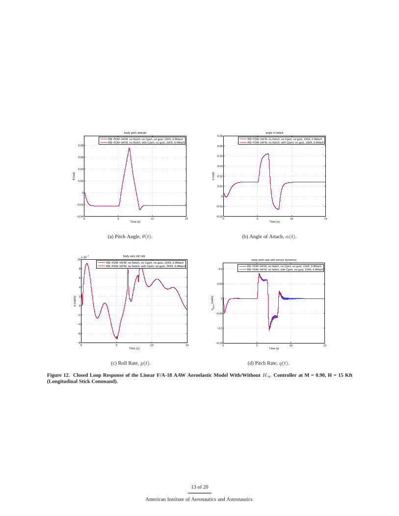
At flight simulation condition M = 0.90, H = 15 Kft, the simulation results with the feedback controller in the loopare plotted in Figures 12, 13, and 14. The simulation resultsobtained at M = 0.90, H = 15 Kft are similar as those atM = 0.85, H = 15 Kft. It is also observed that:
6 of 20
American Institute of Aeronautics and Astronautics

0 5 10 15−1
−0.5
0
0.5
1
1.5
2
2.5
3
3.5
Time (s)
NZ
plt (
g)
body normal acceleration at cockpit
RB−FDM−IAFM, no Notch, no Cpert, no gust, 15Kft, 0.85MachRB−FDM−IAFM, with Notch, no Cpert, no gust, 15Kft, 0.85Mach
(a) Normal Accel. at Pilot Location,NzPlt.
0 5 10 15−1
−0.5
0
0.5
1
1.5
2
2.5
3
3.5
Time (s)
NZ
sens
(g)
body normal acceleration at accelerometer
RB−FDM−IAFM, no Notch, no Cpert, no gust, 15Kft, 0.85MachRB−FDM−IAFM, with Notch, no Cpert, no gust, 15Kft, 0.85Mach
(b) Normal Accel. at Sensor Position,NzSNS .
0 5 10 15−1
0
1
2
3
4
Time (s)
NZ
KM
023R
(g)
body normal acceleration at right wing folder
RB−FDM−IAFM, no Notch, no Cpert, no gust, 15Kft, 0.85MachRB−FDM−IAFM, with Notch, no Cpert, no gust, 15Kft, 0.85Mach
(c) Normal Accel. at Right Wing Folder Position,Nzkm023R.
0 5 10 15−1
0
1
2
3
4
Time (s)
NZ
KM
023L
(g)
body normal acceleration at left wing folder
RB−FDM−IAFM, no Notch, no Cpert, no gust, 15Kft, 0.85MachRB−FDM−IAFM, with Notch, no Cpert, no gust, 15Kft, 0.85Mach
(d) Normal Accel. at Left Wing Folder Position,Nzkm023L.
Figure 6. Closed Loop Response of the Linear F/A-18 AAW Aeroelastic Model With/Without Notch Filters at M = 0.85, H = 15 Kft(Longitudinal Stick Command).
• The vibration responses induced by the 9.5 Hz aeroelastic mode are successfully suppressed with the use of theH∞ feedback controller.
• TheH∞ feedback controller has little influence on the rigid dynamics response.
• The H∞ feedback controller cannot reduce the vibration response of the normal acceleration at wing folderposition,Nzkm023R andNzkm023L.
Performance Validation of theH∞ Controller at M = 0.95, H = 15 Kft
At flight simulation condition M = 0.90, H = 15 Kft, the simulation results with the feedback controller in the loopare plotted in Figures 15, 16, and 17. The simulation resultsobtained at M = 0.95, H = 15 Kft are similar as those atM = 0.85, H = 15 Kft and M = 0.90, H = 15 Kft.
Finally, a frequency domain comparison of aeroelastic/aeroservoelastic system with/without notch filter and with/withoutfeedback controller in the loop is illustrated in Figure 18.Figure 18(a) shows bode plot of the aeroelastic/aeroservoelasticmodel from collective trailing edge flapron to the normal acceleration at Sensor Position,Nzsens with and withoutnotch filter, at M = 0.85. The aeroelastic/aeroservoelasticmodel is estimated using the system identification method.Figure 18(b) shows bode plot of the aeroelastic/aeroservoelastic model from collective trailing edge flapron to thenormal acceleration at Sensor Position,Nzsens with and without feedback controller, at M = 0.85. The similar com-parisons are performed at other two flight conditions at M = 0.90 and M = 0.95. From these comparisons, it is observedthat
7 of 20
American Institute of Aeronautics and Astronautics

0 5 10 15 20−1
0
1
Time (s) Lo
ng S
tick
Long Stick
0 5 10 15 20−1
0
1
Time (s)
Late
ral S
tick
Lateral Stick
0 5 10 15 20−1
0
1
Time (s)
Ped
al
Pedal
(a) Doublet Longitudinal Stick Command.
0 5 10 15−1
0
1
2
3
4
5
6
7
Time (s)
Col
l LEF (
deg)
Collective (inboard/outboard & left/right) Leading Edge Flapron
RB−FDM−IAFM, no Notch, no Cpert, no gust, 15Kft, 0.85MachRB−FDM−IAFM, with Notch, no Cpert, no gust, 15Kft, 0.85Mach
(b) Collective LEF,CollLEF .
0 5 10 150
1
2
3
4
5
6
7
8
Time (s)
Col
l TE
F (
deg)
Collective (left/right) inboard Traling Edge Flapron
RB−FDM−IAFM, no Notch, no Cpert, no gust, 15Kft, 0.85MachRB−FDM−IAFM, with Notch, no Cpert, no gust, 15Kft, 0.85Mach
(c) Collective TEF,CollTEF .
0 5 10 15−1
−0.5
0
0.5
1
1.5
2
2.5
3
Time (s)
Col
l ST
AB (
deg)
Collective (left/right) Stabilizer
RB−FDM−IAFM, no Notch, no Cpert, no gust, 15Kft, 0.85MachRB−FDM−IAFM, with Notch, no Cpert, no gust, 15Kft, 0.85Mach
(d) Collective Stabilator,CollSTAB .
Figure 7. Closed Loop Response of the Linear F/A-18 AAW Aeroelastic Model With/Without Notch Filter at M = 0.85, H = 15 Kft(Longitudinal Stick Command).
• If the frequency change of the elastic modes is small, the notch filter indeed helps to reduce the aeroelas-tic/aeroservoelastic mode interaction.
• It is feasible to apply the adaptive control algorithm for the suppression of the aeroelastic/seroservoelastic modeinteraction instead of using notch filters.
8 of 20
American Institute of Aeronautics and Astronautics

−80
−60
−40
−20
0
20
Mag
nitu
de (
dB)
100
101
102
−180
−90
0
90
180
Pha
se (
deg)
Bode Diagram
Frequency (Hz)
Weighting Function W
(a) Weighting FunctionW .
10−2
10−1
100
101
102
−150
−100
−50
0
50
mag
[dB
]
Bode Response of Cpert
controller
10−2
10−1
100
101
102
−200
0
200
400
f [Hz]
phas
e [d
eg]
(b) Bode Plot of the Controller.
10−2
10−1
100
101
102
−40
−30
−20
−10
0
mag
[dB
]
Bode Response of uncontrolled and controlled system
Uncontrolled (without Cpert
)
Controlled with Cpert
10−2
10−1
100
101
102
−200
−100
0
100
f [Hz]
phas
e [d
eg]
(c) Frequency Domain Comparison.
0 1 2 3 4 50.12
0.14
0.16
0.18
0.2
0.22
0.24
0.26
0.28
0.3
time [sec]
NZ
SN
S
(g)
Step Response of uncontrolled and controlled system
Uncontrolled (without Cpert
)
Controlled with Cpert
(d) Time Domain Comparison.
Figure 8. Results of theH∞ Control Synthesis at M =0.85, H = 15 Kft (UsingCollTEF and NzSNS for Feedback Connection).
9 of 20
American Institute of Aeronautics and Astronautics

0 5 10 15−0.02
0
0.02
0.04
0.06
0.08
0.1
Time (s)
θ (r
ad)
body pitch attitude
RB−FDM−IAFM, no Notch, no Cpert, no gust, 15Kft, 0.85MachRB−FDM−IAFM, no Notch, with Cpert, no gust, 15Kft, 0.85Mach
(a) Pitch Angle,θ(t).
0 5 10 15−0.02
−0.01
0
0.01
0.02
0.03
0.04
0.05
0.06
Time (s)
α (r
ad)
angle of attack
RB−FDM−IAFM, no Notch, no Cpert, no gust, 15Kft, 0.85MachRB−FDM−IAFM, no Notch, with Cpert, no gust, 15Kft, 0.85Mach
(b) Angle of Attach,α(t).
0 5 10 15−0.005
0
0.005
0.01
0.015
0.02
0.025
0.03
0.035
0.04
0.045
Time (s)
p (r
ad/s
)
body axis roll rate
RB−FDM−IAFM, no Notch, no Cpert, no gust, 15Kft, 0.85MachRB−FDM−IAFM, no Notch, with Cpert, no gust, 15Kft, 0.85Mach
(c) Roll Rate,p(t).
0 5 10 15−0.1
−0.08
−0.06
−0.04
−0.02
0
0.02
0.04
0.06
0.08
Time (s)
q sens
(ra
d/s)
body pitch rate with sensor dynamics
RB−FDM−IAFM, no Notch, no Cpert, no gust, 15Kft, 0.85MachRB−FDM−IAFM, no Notch, with Cpert, no gust, 15Kft, 0.85Mach
(d) Pitch Rate,q(t).
Figure 9. Closed Loop Response of the Linear F/A-18 AAW Aeroelastic Model With/Without H∞ Controller at M = 0.85, H = 15 Kft(Longitudinal Stick Command).
10 of 20
American Institute of Aeronautics and Astronautics

0 5 10 15−1
−0.5
0
0.5
1
1.5
2
2.5
3
3.5
Time (s)
NZ
plt (
g)
body normal acceleration at cockpit
RB−FDM−IAFM, no Notch, no Cpert, no gust, 15Kft, 0.85MachRB−FDM−IAFM, no Notch, with Cpert, no gust, 15Kft, 0.85Mach
(a) Normal Accel. at Pilot Location,NzPlt.
0 5 10 15−1
−0.5
0
0.5
1
1.5
2
2.5
3
3.5
Time (s)
NZ
sens
(g)
body normal acceleration at accelerometer
RB−FDM−IAFM, no Notch, no Cpert, no gust, 15Kft, 0.85MachRB−FDM−IAFM, no Notch, with Cpert, no gust, 15Kft, 0.85Mach
(b) Normal Accel. at Sensor Position,NzSNS .
0 5 10 15−1
0
1
2
3
4
Time (s)
NZ
KM
023R
(g)
body normal acceleration at right wing folder
RB−FDM−IAFM, no Notch, no Cpert, no gust, 15Kft, 0.85MachRB−FDM−IAFM, no Notch, with Cpert, no gust, 15Kft, 0.85Mach
(c) Normal Accel. at Right Wing Folder Position,Nzkm023R.
0 5 10 15−1
0
1
2
3
4
Time (s)
NZ
KM
023L
(g)
body normal acceleration at left wing folder
RB−FDM−IAFM, no Notch, no Cpert, no gust, 15Kft, 0.85MachRB−FDM−IAFM, no Notch, with Cpert, no gust, 15Kft, 0.85Mach
(d) Normal Accel. at Left Wing Folder Position,Nzkm023L.
Figure 10. Closed Loop Response of the Linear F/A-18 AAW Aeroelastic Model With/Without H∞ Controller at M = 0.85, H = 15 Kft(Longitudinal Stick Command).
11 of 20
American Institute of Aeronautics and Astronautics

0 5 10 15 20−1
0
1
Time (s)
Long
Stic
k
Long Stick
0 5 10 15 20−1
0
1
Time (s)
Late
ral S
tick
Lateral Stick
0 5 10 15 20−1
0
1
Time (s)
Ped
al
Pedal
(a) Doublet Longitudinal Stick Command.
0 5 10 15−1
0
1
2
3
4
5
6
7
Time (s)
Col
l LEF (
deg)
Collective (inboard/outboard & left/right) Leading Edge Flapron
RB−FDM−IAFM, no Notch, no Cpert, no gust, 15Kft, 0.85MachRB−FDM−IAFM, no Notch, with Cpert, no gust, 15Kft, 0.85Mach
(b) Collective LEF,CollLEF .
0 5 10 15−1
0
1
2
3
4
5
6
7
8
Time (s)
Col
l TE
F (
deg)
Collective (left/right) inboard Traling Edge Flapron
RB−FDM−IAFM, no Notch, no Cpert, no gust, 15Kft, 0.85MachRB−FDM−IAFM, no Notch, with Cpert, no gust, 15Kft, 0.85Mach
(c) Collective TEF,CollTEF .
0 5 10 15−1
−0.5
0
0.5
1
1.5
2
2.5
3
Time (s)
Col
l ST
AB (
deg)
Collective (left/right) Stabilizer
RB−FDM−IAFM, no Notch, no Cpert, no gust, 15Kft, 0.85MachRB−FDM−IAFM, no Notch, with Cpert, no gust, 15Kft, 0.85Mach
(d) Collective Stabilator,CollSTAB .
Figure 11. Closed Loop Response of the Linear F/A-18 AAW Aeroelastic Model With/Without H∞ Controller at M = 0.85, H = 15 Kft(Longitudinal Stick Command).
12 of 20
American Institute of Aeronautics and Astronautics
0 5 10 15−0.04
−0.02
0
0.02
0.04
0.06
0.08
Time (s)
θ (r
ad)
body pitch attitude
RB−FDM−IAFM, no Notch, no Cpert, no gust, 15Kft, 0.9MachRB−FDM−IAFM, no Notch, with Cpert, no gust, 15Kft, 0.9Mach
(a) Pitch Angle,θ(t).
0 5 10 15−0.02
−0.01
0
0.01
0.02
0.03
0.04
0.05
0.06
Time (s)
α (r
ad)
angle of attack
RB−FDM−IAFM, no Notch, no Cpert, no gust, 15Kft, 0.9MachRB−FDM−IAFM, no Notch, with Cpert, no gust, 15Kft, 0.9Mach
(b) Angle of Attach,α(t).
0 5 10 15−8
−6
−4
−2
0
2
4
6
8
10x 10
−3
Time (s)
p (r
ad/s
)
body axis roll rate
RB−FDM−IAFM, no Notch, no Cpert, no gust, 15Kft, 0.9MachRB−FDM−IAFM, no Notch, with Cpert, no gust, 15Kft, 0.9Mach
(c) Roll Rate,p(t).
0 5 10 15−0.15
−0.1
−0.05
0
0.05
0.1
Time (s)
q sens
(ra
d/s)
body pitch rate with sensor dynamics
RB−FDM−IAFM, no Notch, no Cpert, no gust, 15Kft, 0.9MachRB−FDM−IAFM, no Notch, with Cpert, no gust, 15Kft, 0.9Mach
(d) Pitch Rate,q(t).
Figure 12. Closed Loop Response of the Linear F/A-18 AAW Aeroelastic Model With/Without H∞ Controller at M = 0.90, H = 15 Kft(Longitudinal Stick Command).
13 of 20
American Institute of Aeronautics and Astronautics

0 5 10 15−1
−0.5
0
0.5
1
1.5
2
2.5
3
3.5
Time (s)
NZ
plt (
g)
body normal acceleration at cockpit
RB−FDM−IAFM, no Notch, no Cpert, no gust, 15Kft, 0.9MachRB−FDM−IAFM, no Notch, with Cpert, no gust, 15Kft, 0.9Mach
(a) Normal Accel. at Pilot Location,NzPlt.
0 5 10 15−1
−0.5
0
0.5
1
1.5
2
2.5
3
3.5
Time (s)
NZ
sens
(g)
body normal acceleration at accelerometer
RB−FDM−IAFM, no Notch, no Cpert, no gust, 15Kft, 0.9MachRB−FDM−IAFM, no Notch, with Cpert, no gust, 15Kft, 0.9Mach
(b) Normal Accel. at Sensor Position,NzSNS .
0 5 10 15−2
−1
0
1
2
3
4
Time (s)
NZ
KM
023R
(g)
body normal acceleration at right wing folder
RB−FDM−IAFM, no Notch, no Cpert, no gust, 15Kft, 0.9MachRB−FDM−IAFM, no Notch, with Cpert, no gust, 15Kft, 0.9Mach
(c) Normal Accel. at Right Wing Folder Position,Nzkm023R.
0 5 10 15−2
−1
0
1
2
3
4
Time (s)
NZ
KM
023L
(g)
body normal acceleration at left wing folder
RB−FDM−IAFM, no Notch, no Cpert, no gust, 15Kft, 0.9MachRB−FDM−IAFM, no Notch, with Cpert, no gust, 15Kft, 0.9Mach
(d) Normal Accel. at Left Wing Folder Position,Nzkm023L.
Figure 13. Closed Loop Response of the Linear F/A-18 AAW Aeroelastic Model With/Without H∞ Controller at M = 0.90, H = 15 Kft(Longitudinal Stick Command).
14 of 20
American Institute of Aeronautics and Astronautics

0 5 10 15 20−1
0
1
Time (s)
Long
Stic
k
Long Stick
0 5 10 15 20−1
0
1
Time (s)
Late
ral S
tick
Lateral Stick
0 5 10 15 20−1
0
1
Time (s)
Ped
al
Pedal
(a) Doublet Longitudinal Stick Command.
0 5 10 151
1.5
2
2.5
3
3.5
4
Time (s)
Col
l LEF (
deg)
Collective (inboard/outboard & left/right) Leading Edge Flapron
RB−FDM−IAFM, no Notch, no Cpert, no gust, 15Kft, 0.9MachRB−FDM−IAFM, no Notch, with Cpert, no gust, 15Kft, 0.9Mach
(b) Collective LEF,CollLEF .
0 5 10 15−1
0
1
2
3
4
5
6
7
Time (s)
Col
l TE
F (
deg)
Collective (left/right) inboard Traling Edge Flapron
RB−FDM−IAFM, no Notch, no Cpert, no gust, 15Kft, 0.9MachRB−FDM−IAFM, no Notch, with Cpert, no gust, 15Kft, 0.9Mach
(c) Collective TEF,CollTEF .
0 5 10 15−3
−2
−1
0
1
2
3
Time (s)
Col
l ST
AB (
deg)
Collective (left/right) Stabilizer
RB−FDM−IAFM, no Notch, no Cpert, no gust, 15Kft, 0.9MachRB−FDM−IAFM, no Notch, with Cpert, no gust, 15Kft, 0.9Mach
(d) Collective Stabilator,CollSTAB .
Figure 14. Closed Loop Response of the Linear F/A-18 AAW Aeroelastic Model With/Without H∞ Controller at M = 0.90, H = 15 Kft(Longitudinal Stick Command).
15 of 20
American Institute of Aeronautics and Astronautics

0 5 10 150
0.02
0.04
0.06
0.08
0.1
0.12
Time (s)
θ (r
ad)
body pitch attitude
RB−FDM−IAFM, no Notch, no Cpert, no gust, 15Kft, 0.94MachRB−FDM−IAFM, no Notch, with Cpert, no gust, 15Kft, 0.94Mach
(a) Pitch Angle,θ(t).
0 5 10 15−0.01
0
0.01
0.02
0.03
0.04
0.05
Time (s)
α (r
ad)
angle of attack
RB−FDM−IAFM, no Notch, no Cpert, no gust, 15Kft, 0.94MachRB−FDM−IAFM, no Notch, with Cpert, no gust, 15Kft, 0.94Mach
(b) Angle of Attach,α(t).
0 5 10 15−0.02
−0.01
0
0.01
0.02
0.03
0.04
Time (s)
p (r
ad/s
)
body axis roll rate
RB−FDM−IAFM, no Notch, no Cpert, no gust, 15Kft, 0.94MachRB−FDM−IAFM, no Notch, with Cpert, no gust, 15Kft, 0.94Mach
(c) Roll Rate,p(t).
0 5 10 15−0.1
−0.08
−0.06
−0.04
−0.02
0
0.02
0.04
0.06
0.08
Time (s)
q sens
(ra
d/s)
body pitch rate with sensor dynamics
RB−FDM−IAFM, no Notch, no Cpert, no gust, 15Kft, 0.94MachRB−FDM−IAFM, no Notch, with Cpert, no gust, 15Kft, 0.94Mach
(d) Pitch Rate,q(t).
Figure 15. Closed Loop Response of the Linear F/A-18 AAW Aeroelastic Model With/Without H∞ Controller at M = 0.95, H = 15 Kft(Longitudinal Stick Command).
16 of 20
American Institute of Aeronautics and Astronautics

0 5 10 15−1
−0.5
0
0.5
1
1.5
2
2.5
3
3.5
Time (s)
NZ
plt (
g)
body normal acceleration at cockpit
RB−FDM−IAFM, no Notch, no Cpert, no gust, 15Kft, 0.94MachRB−FDM−IAFM, no Notch, with Cpert, no gust, 15Kft, 0.94Mach
(a) Normal Accel. at Pilot Location,NzPlt.
0 5 10 15−1
−0.5
0
0.5
1
1.5
2
2.5
3
3.5
Time (s)
NZ
sens
(g)
body normal acceleration at accelerometer
RB−FDM−IAFM, no Notch, no Cpert, no gust, 15Kft, 0.94MachRB−FDM−IAFM, no Notch, with Cpert, no gust, 15Kft, 0.94Mach
(b) Normal Accel. at Sensor Position,NzSNS .
0 5 10 15−2
−1
0
1
2
3
4
Time (s)
NZ
KM
023R
(g)
body normal acceleration at right wing folder
RB−FDM−IAFM, no Notch, no Cpert, no gust, 15Kft, 0.94MachRB−FDM−IAFM, no Notch, with Cpert, no gust, 15Kft, 0.94Mach
(c) Normal Accel. at Right Wing Folder Position,Nzkm023R.
0 5 10 15−2
−1
0
1
2
3
4
Time (s)
NZ
KM
023L
(g)
body normal acceleration at left wing folder
RB−FDM−IAFM, no Notch, no Cpert, no gust, 15Kft, 0.94MachRB−FDM−IAFM, no Notch, with Cpert, no gust, 15Kft, 0.94Mach
(d) Normal Accel. at Left Wing Folder Position,Nzkm023L.
Figure 16. Closed Loop Response of the Linear F/A-18 AAW Aeroelastic Model With/Without H∞ Controller at M = 0.95, H = 15 Kft(Longitudinal Stick Command).
17 of 20
American Institute of Aeronautics and Astronautics

0 5 10 15 20−1
0
1
Time (s)
Long
Stic
k
Long Stick
0 5 10 15 20−1
0
1
Time (s)
Late
ral S
tick
Lateral Stick
0 5 10 15 20−1
0
1
Time (s)
Ped
al
Pedal
(a) Doublet Longitudinal Stick Command.
0 5 10 15
1.8
2
2.2
2.4
2.6
2.8
3
Time (s)
Col
l LEF (
deg)
Collective (inboard/outboard & left/right) Leading Edge Flapron
RB−FDM−IAFM, no Notch, no Cpert, no gust, 15Kft, 0.94MachRB−FDM−IAFM, no Notch, with Cpert, no gust, 15Kft, 0.94Mach
(b) Collective LEF,CollLEF .
0 5 10 151
1.5
2
2.5
3
3.5
4
4.5
5
5.5
6
Time (s)
Col
l TE
F (
deg)
Collective (left/right) inboard Traling Edge Flapron
RB−FDM−IAFM, no Notch, no Cpert, no gust, 15Kft, 0.94MachRB−FDM−IAFM, no Notch, with Cpert, no gust, 15Kft, 0.94Mach
(c) Collective TEF,CollTEF .
0 5 10 15−2.5
−2
−1.5
−1
−0.5
0
0.5
1
1.5
Time (s)
Col
l ST
AB (
deg)
Collective (left/right) Stabilizer
RB−FDM−IAFM, no Notch, no Cpert, no gust, 15Kft, 0.94MachRB−FDM−IAFM, no Notch, with Cpert, no gust, 15Kft, 0.94Mach
(d) Collective Stabilator,CollSTAB .
Figure 17. Closed Loop Response of the Linear F/A-18 AAW Aeroelastic Model With/Without H∞ Controller at M = 0.95, H = 15 Kft(Longitudinal Stick Command).
18 of 20
American Institute of Aeronautics and Astronautics

10−2
10−1
100
101
102
−40
−30
−20
−10
0
mag
[dB
]
Without NotchWith Notch
10−2
10−1
100
101
102
−200
−100
0
100
f [Hz]
phas
e [d
eg]
(a) Effect of Notch Filter at M = 0.85.
10−2
10−1
100
101
102
−40
−30
−20
−10
0
mag
[dB
]
Uncontrolled (without Cpert
)
Controlled with Cpert
10−2
10−1
100
101
102
−200
−100
0
100
200
f [Hz]
phas
e [d
eg]
(b) Effect of Controller at M = 0.85.
10−2
10−1
100
101
102
−40
−30
−20
−10
0
mag
[dB
]
Without NotchWith Notch
10−2
10−1
100
101
102
−200
−100
0
100
f [Hz]
phas
e [d
eg]
(c) Effect of Notch Filter at M = 0.90.
10−2
10−1
100
101
102
−40
−30
−20
−10
0
mag
[dB
]
Uncontrolled (without Cpert
)
Controlled with Cpert
10−2
10−1
100
101
102
−200
0
200
400
f [Hz]
phas
e [d
eg]
(d) Effect of Controller at M = 0.90.
10−2
10−1
100
101
102
−40
−30
−20
−10
0
mag
[dB
]
Without NotchWith Notch
10−2
10−1
100
101
102
−200
−100
0
100
200
f [Hz]
phas
e [d
eg]
(e) Effect of Notch Filter at M = 0.95.
10−2
10−1
100
101
102
−40
−30
−20
−10
0
mag
[dB
]
Uncontrolled (without Cpert
)
Controlled with Cpert
10−2
10−1
100
101
102
−200
0
200
400
f [Hz]
phas
e [d
eg]
(f) Effect of Controller at M = 0.95.
Figure 18. Performance Comparison of the Notch Filter and Feedback Controller on Suppression of the Aeroelastic Modes Interaction.
19 of 20
American Institute of Aeronautics and Astronautics

V. Conclusions
In this paper, the possibility of applying an adaptive feedback control for the suppression of aircraft’s structuralvibration in the presence of any aeroelastic/aeroservoelastic interaction was investigated. In addition, the effectivenessof implementation of the notch filters in the flight control system for aeroelastic/aeroservoelastic vibration suppressionwas also studied. In the case that the change of the aircraft configuration is not significant, i.e., the frequencies of theflexible modes of the aircraft only have small changes, the non-adaptive notch filters shall work properly. On the otherhand, with the proposed adaptive feedback control technology, the flexible dynamics can be consistently monitoredand estimated via system identification algorithms, and itsundesirable effects can be successfully minimized througha design of the robust feedback control law. Therefore, if the changes of the aircraft configuration are significant, theproposed adaptive feedback control outperforms the notch filters for the suppression of the aeroelastic/aeroservoelasticmodes interaction.
Acknowledgments
Research is supported by NASA Dryden Flight Research Centerunder Small Business Innovation Research (SBIR)Phase II contract NNX09CB63C.
References1Overschee, P. and de Moor, B.,Subspace Identifiction for Linear Systems:Theory-Implementation-Applications, Kluwer Academic Publisher,
Dordrecht, Belgium, 1996.2de Callafon, R., Miller, D. N., Zeng, J., and Brenner, M. J., “Step Based Experiment Design and System Identification for Aeroelastic
Dynamic Modeling,”AIAA Atmospheric Flight Mechanics Conference, Chicago, IL, 2009, AIAA-2009-5707.3Glover, K. and McFarlane, D., “Robust Stabilization of Normalized Coprime Factor Plant Descriptions withH∞–Bounded Uncertainty,”
IEEE Trans. on Automatic Control, AC–34, 1989, pp. 821–830.
20 of 20
American Institute of Aeronautics and Astronautics