surecrossâ„¢ dx99 wireless device control drawings
TRANSCRIPT

Printed in USA 03 May 2010 P/N 141513 rev. C
SureCross™ DX99 Wireless Device Control Drawings
DX9x Model Numbering Scheme . . . . . . . . . . . . . . . . . . . . . . . . . 2Control Drawing Notes . . . . . . . . . . . . . . . . . . . . . . . . . . . . . . . . . 3FlexPower™ Node, 2020 (DX99...A and DX99...B) . . . . . . . . . . . 4FlexPower™ Node, 2020 (DX99...D Housing) . . . . . . . . . . . . . . 11Thermocouple Nodes . . . . . . . . . . . . . . . . . . . . . . . . . . . . . . . . . 18Thermocouple Nodes (DX99...D Housing) . . . . . . . . . . . . . . . . . 19RTD Nodes . . . . . . . . . . . . . . . . . . . . . . . . . . . . . . . . . . . . . . . . . 20RTD Nodes (DX99...D Housing) . . . . . . . . . . . . . . . . . . . . . . . . . 21Bridge . . . . . . . . . . . . . . . . . . . . . . . . . . . . . . . . . . . . . . . . . . . . . 22Bridge (DX99...D Housing) . . . . . . . . . . . . . . . . . . . . . . . . . . . . . 23Bridge and Thermistor . . . . . . . . . . . . . . . . . . . . . . . . . . . . . . . . . 24Bridge and Thermistor (DX99...D Housing) . . . . . . . . . . . . . . . . 25Control Drawings - IS Power Converter Nodes . . . . . . . . . . . . . 26
Line Power Configuration A - 4 V+ . . . . . . . . . . . . . . . . . . . . . 26Line Power Configuration B - 4 SP . . . . . . . . . . . . . . . . . . . . . 27Line Power Configuration C - 2 V+, 2SP . . . . . . . . . . . . . . . . 28
Weather-Proofing Glands and Plugs . . . . . . . . . . . . . . . . . . . . . . 29DX81H Battery Replacement . . . . . . . . . . . . . . . . . . . . . . . . . . . 30Metal Enclosure Battery Replacement . . . . . . . . . . . . . . . . . . . . 31
CSA C/US Class I, Division 1, Groups A, B, C, D Class I, Zone 0, Group IICClass II, Division 1, Groups E, F, G Class III, Division 1
LCIE/ATEX Group IIC, Zone 0Dust, Zone 20

Banner Engineering Corp. • Minneapolis, MN U.S.A www.bannerengineering.com • Tel: 763.544.31642 P/N 141513 rev. C
SureCross™ Intrinsically Safe Control Drawings (DX99...A/B/D)
DX9x Model Numbering Scheme
Radio Comms Config. Discrete I/O Analog I/O
DX99 G 9 X 2 S 2 N 0 M 2 X 0 A 1 X
Radio ModelDX99 - Class I, Div 1
Device TypeD - Data Radio
G - GatewayN - Node
Radio Technology9 - 900 MHz FHSS2 - 2.4 GHz FHSS
Host Comms TypeX - None
C - Custom
Power Type1 - FlexPower™, battery
2 - FlexPower™, no battery6 - 10–30V dc, no battery
AntennaS - ExternalW - Internal
X - No antenna
Discrete Input Qty0, 2, 4
Discrete TypeA - Asynchronous counter
N - NPNP - PNP
X - None
Discrete Output Qty0
Analog Input TypeB - BridgeC - Bridge and thermistorE - Event counterF - Frequency counterM - 0 to 20 mAR - RTDT - ThermcoupleV - 0 to 10V dc
X - None
Analog Input Qty0, 1, 2, 4
Analog Output TypeX - None
Analog Output Qty0
Enclosure*A - PolycarbonateB - Metal housingD - Low profile metal housing
FlexPower Boost Volt.*0 - No boost (3.6V)1 - 10V2 - 18V3 - 20V
Battery-powered DX99 devices must only use the DX81H battery device.
Custom Configuration Identifierblank - StandardX - Special

P/N 141513 rev. C 3Banner Engineering Corp. • Minneapolis, MN U.S.A
www.bannerengineering.com • Tel: 763.544.3164
SureCross™ Intrinsically Safe Control Drawings (DX99...A/B/D)
WARNING: Do not open when an explosive atmosphere may be present (versions with metal enclosure).• WARNING: Potential electrostatic charging hazard - Only clean with a damp cloth (versions with plastic enclosure).• Exia is defined as INTRINSICALLY SAFE• WARNING: Substitution of components may impair intrinsic safety.• When using battery-powered DX99 devices in plastic enclosures, only use the IS battery unit, model DX81H, to power the devices. When • replacing the battery, only use a 3.6V lithium battery from Xeno, model number XL-205F.Choose peripheral devices and associated apparatuses such that the following conditions are met:•
Ui/Vmax ≥ Uo/Voc Ii/Imax ≥ Io/Isc Pi ≥ Po Co/Ca ≥ Ci + Ccable Lo/La ≥ Li + Lcable
If a remote antenna is used, the cable length should not exceed 30 meters or 100 feet.• When the Limatherm enclosure is used in Dust Atmospheres, use approved cable glands (with suitable cable) or other acceptable wiring • methods for Class II/III Division 1 in accordance with local installation codes (CEC for Canada and NEC for the United States). For Europe, the cable glands must be Certified for the ATEX rating II 1 D.All devices and barriers connected to the DX99 units use different Intrinsically Safe circuits that must be kept separate from each other at • all times. This may be achieved in one of two ways: (1) route different circuits in separate cables, or (2) route different circuits in the same cable separated by a grounded shield. The circuits of different devices that are all connected to powered outputs (SP1, SP2, SP3, and/or SP4) do not need to be separated from each other.
Control Drawing Notes

Banner Engineering Corp. • Minneapolis, MN U.S.A www.bannerengineering.com • Tel: 763.544.31644 P/N 141513 rev. C
SureCross™ Intrinsically Safe Control Drawings (DX99...A/B/D)
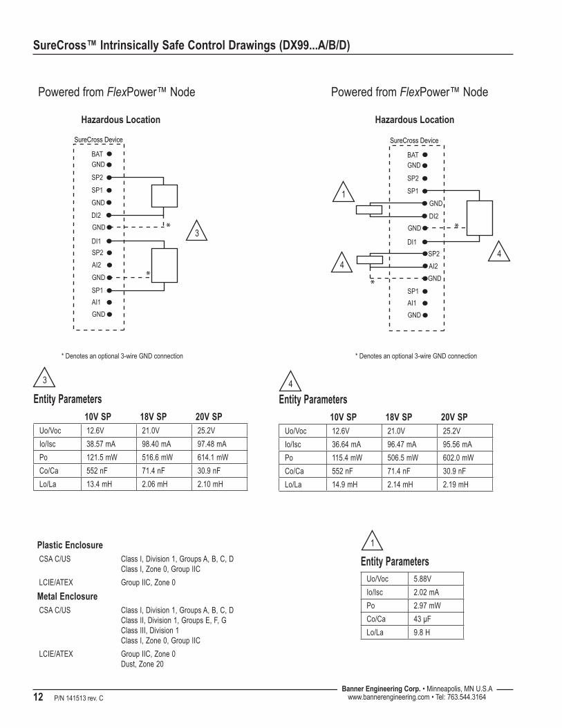
FlexPower™ Node, 2020 (DX99...A and DX99...B)
A2+
GND
DI1DI2
SP2
GND
SP1
GND
A1+
GND
SP1SP2
GNDGND
GNDGND
Hazardous Location
SureCross Device
Powered from FlexPower™ Node
Entity ParametersUo/Voc 5.88V
Io/Isc 2.02 mA
Po 2.97 mW
Co/Ca 43 μF
Lo/La 9.8 H
A2+
GND
DI1DI2
SP2
GND
SP1
GND
A1+
GND
SP1SP2
GNDGND
GNDGND
Powered from FlexPower™ Node
*
Hazardous Location
SureCross Device
* Denotes an optional 3-wire GND connection
Entity Parameters10V SP 18V SP 20V SP
Uo/Voc 12.6V 21.0V 25.2V
Io/Isc 36.55 mA 96.38 mA 95.47 mA
Po 115.1 mW 506.0 mW 601.5 mW
Co/Ca 1105 nF 142.9 nF 61.9 nF
Lo/La 29.94 mH 4.30 mH 4.38 mH
1
11 1
2
2
Plastic EnclosureCSA C/US Class I, Division 1, Groups A, B, C, D
Class I, Zone 0, Group IIC
LCIE/ATEX Group IIC, Zone 0
Metal EnclosureCSA C/US Class I, Division 1, Groups A, B, C, D
Class II, Division 1, Groups E, F, G Class III, Division 1 Class I, Zone 0, Group IIC
LCIE/ATEX Group IIC, Zone 0 Dust, Zone 20

P/N 141513 rev. C 5Banner Engineering Corp. • Minneapolis, MN U.S.A
www.bannerengineering.com • Tel: 763.544.3164
SureCross™ Intrinsically Safe Control Drawings (DX99...A/B/D)
A2+
GND
DI1DI2
SP2
GND
SP1
GND
A1+
GND
SP1SP2
GNDGND
GNDGND
**
Hazardous Location
SureCross Device
Powered from FlexPower™ Node
* Denotes an optional 3-wire GND connection
A2+
GND
DI1DI2
SP2
GND
SP1
GND
A1+
GND
SP1SP2
GNDGND
GNDGND
*
*
Hazardous Location
SureCross Device
Powered from FlexPower™ Node
* Denotes an optional 3-wire GND connection
Entity Parameters10V SP 18V SP 20V SP
Uo/Voc 12.6V 21.0V 25.2V
Io/Isc 38.57 mA 98.40 mA 97.48 mA
Po 121.5 mW 516.6 mW 614.1 mW
Co/Ca 552 nF 71.4 nF 30.9 nF
Lo/La 13.4 mH 2.06 mH 2.10 mH
3
33
Entity Parameters10V SP 18V SP 20V SP
Uo/Voc 12.6V 21.0V 25.2V
Io/Isc 36.64 mA 96.47 mA 95.56 mA
Po 115.4 mW 506.5 mW 602.0 mW
Co/Ca 552 nF 71.4 nF 30.9 nF
Lo/La 14.9 mH 2.14 mH 2.19 mH
4
4
4
1
Entity ParametersUo/Voc 5.88V
Io/Isc 2.02 mA
Po 2.97 mW
Co/Ca 43 μF
Lo/La 9.8 H
1Plastic EnclosureCSA C/US Class I, Division 1, Groups A, B, C, D
Class I, Zone 0, Group IIC
LCIE/ATEX Group IIC, Zone 0
Metal EnclosureCSA C/US Class I, Division 1, Groups A, B, C, D
Class II, Division 1, Groups E, F, G Class III, Division 1 Class I, Zone 0, Group IIC
LCIE/ATEX Group IIC, Zone 0 Dust, Zone 20

Banner Engineering Corp. • Minneapolis, MN U.S.A www.bannerengineering.com • Tel: 763.544.31646 P/N 141513 rev. C
SureCross™ Intrinsically Safe Control Drawings (DX99...A/B/D)
A2+
GND
DI1DI2
SP2
GND
SP1
GND
A1+
GND
SP1SP2
GNDGND
GNDGND
* *
Hazardous Location
SureCross Device
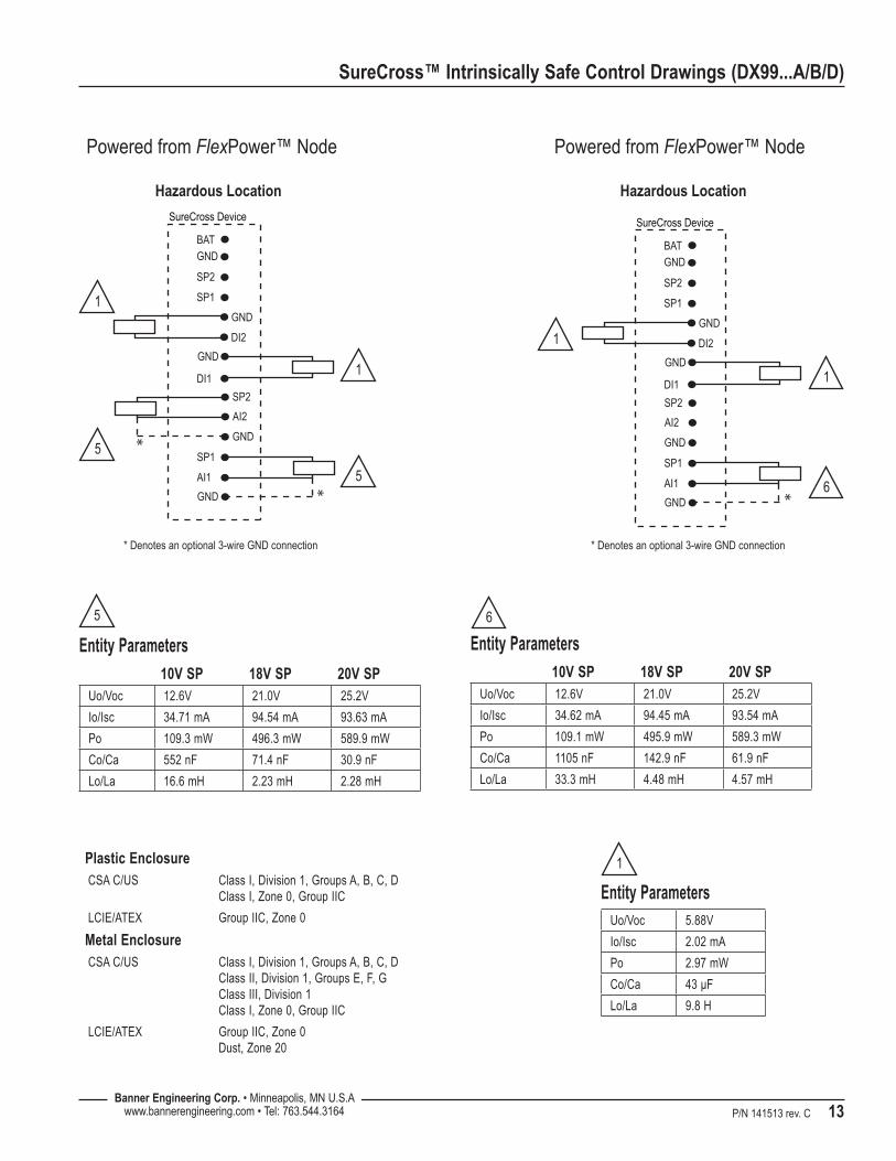
Powered from FlexPower™ Node
* Denotes an optional 3-wire GND connection
A2+
GND
DI1DI2
SP2
GND
SP1
GND
A1+
GND
SP1SP2
GNDGND
GNDGND
*
Hazardous Location
SureCross Device
Powered from FlexPower™ Node
* Denotes an optional 3-wire GND connection
Entity Parameters10V SP 18V SP 20V SP
Uo/Voc 12.6V 21.0V 25.2V
Io/Isc 34.71 mA 94.54 mA 93.63 mA
Po 109.3 mW 496.3 mW 589.9 mW
Co/Ca 552 nF 71.4 nF 30.9 nF
Lo/La 16.6 mH 2.23 mH 2.28 mH
5
55
11
Entity Parameters10V SP 18V SP 20V SP
Uo/Voc 12.6V 21.0V 25.2V
Io/Isc 34.62 mA 94.45 mA 93.54 mA
Po 109.1 mW 495.9 mW 589.3 mW
Co/Ca 1105 nF 142.9 nF 61.9 nF
Lo/La 33.3 mH 4.48 mH 4.57 mH
6
11
6
Entity ParametersUo/Voc 5.88V
Io/Isc 2.02 mA
Po 2.97 mW
Co/Ca 43 μF
Lo/La 9.8 H
1Plastic EnclosureCSA C/US Class I, Division 1, Groups A, B, C, D
Class I, Zone 0, Group IIC
LCIE/ATEX Group IIC, Zone 0
Metal EnclosureCSA C/US Class I, Division 1, Groups A, B, C, D
Class II, Division 1, Groups E, F, G Class III, Division 1 Class I, Zone 0, Group IIC
LCIE/ATEX Group IIC, Zone 0 Dust, Zone 20

P/N 141513 rev. C 7Banner Engineering Corp. • Minneapolis, MN U.S.A
www.bannerengineering.com • Tel: 763.544.3164
SureCross™ Intrinsically Safe Control Drawings (DX99...A/B/D)
A2+
GND
DI1DI2
SP2
GND
SP1
GND
A1+
GND
SP1SP2
GNDGND
GNDGND
*
**
*
Hazardous Location
SureCross Device
Powered from FlexPower™ Node
* Denotes an optional 3-wire GND connection
Entity Parameters10V SP 18V SP 20V SP
Uo/Voc 12.6V 21.0V 25.2V
Io/Isc 38.75 mA 98.58 mA 97.66 mA
Po 122.1 mW 517.5 mW 615.3 mW
Co/Ca 276 nF 35.7 nF 15.4 nF
Lo/La 6.65 mH 1.02 mH 1.04 mH
7
7
7
7
7
Plastic EnclosureCSA C/US Class I, Division 1, Groups A, B, C, D
Class I, Zone 0, Group IIC
LCIE/ATEX Group IIC, Zone 0
Metal EnclosureCSA C/US Class I, Division 1, Groups A, B, C, D
Class II, Division 1, Groups E, F, G Class III, Division 1 Class I, Zone 0, Group IIC
LCIE/ATEX Group IIC, Zone 0 Dust, Zone 20

Banner Engineering Corp. • Minneapolis, MN U.S.A www.bannerengineering.com • Tel: 763.544.31648 P/N 141513 rev. C
SureCross™ Intrinsically Safe Control Drawings (DX99...A/B/D)
A2+
GND
DI1DI2
SP2
GND
SP1
GND
A1+
GND
SP1SP2
GNDGND
GNDGND
*
Hazardous Location
SureCross Device
Powered Externally from FlexPower™ Node
Non-Classified Location
Associated Apparatus Control Equipment
* Denotes an optional 3-wire GND connection
8
2
Entity Parameters10V SP 18V SP 20V SP
Uo/Voc 12.6V 21.0V 25.2V
Io/Isc 36.55 mA 96.38 mA 95.47 mA
Po 115.1 mW 506.0 mW 601.5 mW
Co/Ca 1105 nF 142.9 nF 61.9 nF
Lo/La 29.94 mH 4.30 mH 4.38 mH
2
Entity Parameters10V SP 18V SP 20V SP
Ui/Vmax 30V 30V 30V
Ii/Imax 100 mA 100 mA 100 mA
Pi 3 W 3 W 3W
Ci 0 0 0
Li 0 0 0
8
Plastic EnclosureCSA C/US Class I, Division 1, Groups A, B, C, D
Class I, Zone 0, Group IIC
LCIE/ATEX Group IIC, Zone 0
Metal EnclosureCSA C/US Class I, Division 1, Groups A, B, C, D
Class II, Division 1, Groups E, F, G Class III, Division 1 Class I, Zone 0, Group IIC
LCIE/ATEX Group IIC, Zone 0 Dust, Zone 20

P/N 141513 rev. C 9Banner Engineering Corp. • Minneapolis, MN U.S.A
www.bannerengineering.com • Tel: 763.544.3164
SureCross™ Intrinsically Safe Control Drawings (DX99...A/B/D)
A2+
GND
DI1DI2
SP2
GND
SP1
GND
A1+
GND
SP1SP2
GNDGND
GNDGND
*
*
Hazardous Location
SureCross Device
Powered Externally from FlexPower™ Node
Non-Classified Location
Associated Apparatus Control Equipment
Associated Apparatus Control Equipment
* Denotes an optional 3-wire GND connection
Entity Parameters10V SP 18V SP 20V SP
Ui/Vmax 30V 30V 30V
Ii/Imax 100 mA 100 mA 100 mA
Pi 3 W 3 W 3 W
Ci 0 0 0
Li 0 0 0
8
8
8
4
4
Entity Parameters10V SP 18V SP 20V SP
Uo/Voc 12.6V 21.0V 25.2V
Io/Isc 36.64 mA 96.47 mA 95.56 mA
Po 115.4 mW 506.5 mW 602.0 mW
Co/Ca 552 nF 71.4 nF 30.9 nF
Lo/La 14.9 mH 2.14 mH 2.19 mH
4
Class I, Division 1, Groups A - D Class II, Division 1, Groups E - G Class III, Division 1 ATEX Class I, Zone 0
Plastic EnclosureCSA C/US Class I, Division 1, Groups A, B, C, D
Class I, Zone 0, Group IIC
LCIE/ATEX Group IIC, Zone 0
Metal EnclosureCSA C/US Class I, Division 1, Groups A, B, C, D
Class II, Division 1, Groups E, F, G Class III, Division 1 Class I, Zone 0, Group IIC
LCIE/ATEX Group IIC, Zone 0 Dust, Zone 20

Banner Engineering Corp. • Minneapolis, MN U.S.A www.bannerengineering.com • Tel: 763.544.316410 P/N 141513 rev. C
SureCross™ Intrinsically Safe Control Drawings (DX99...A/B/D)
A2+
GND
DI1DI2
SP2
GND
SP1
GND
A1+
GND
SP1SP2
GNDGND
GNDGND
Hazardous Location
SureCross Device
Powered Externally from FlexPower™ Node
Non-Classified Location
Associated Apparatus
Non-Classified Location
Control Equipment
Associated Apparatus Control Equipment
Associated Apparatus
Associated Apparatus
Control Equipment
Control Equipment
8
88
8
Plastic EnclosureCSA C/US Class I, Division 1, Groups A, B, C, D
Class I, Zone 0, Group IIC
LCIE/ATEX Group IIC, Zone 0
Metal EnclosureCSA C/US Class I, Division 1, Groups A, B, C, D
Class II, Division 1, Groups E, F, G Class III, Division 1 Class I, Zone 0, Group IIC
LCIE/ATEX Group IIC, Zone 0 Dust, Zone 20
Entity Parameters10V SP 18V SP 20V SP
Ui/Vmax 30V 30V 30V
Ii/Imax 100 mA 100 mA 100 mW
Pi 3 W 3 W 3 W
Ci 0 0 0
Li 0 0 0
8

P/N 141513 rev. C 11Banner Engineering Corp. • Minneapolis, MN U.S.A
www.bannerengineering.com • Tel: 763.544.3164
SureCross™ Intrinsically Safe Control Drawings (DX99...A/B/D)
FlexPower™ Node, 2020 (DX99...D Housing)
DI1
GND
SP2
GND
GND
BAT
SP1
DI2
SP2
AI2
GND
SP1
AI1
GND
Hazardous Location
SureCross Device
Powered from FlexPower™ Node
Entity ParametersUo/Voc 5.88V
Io/Isc 2.02 mA
Po 2.97 mW
Co/Ca 43 μF
Lo/La 9.8 H
Powered from FlexPower™ Node
*
Hazardous Location
* Denotes an optional 3-wire GND connection
DI1
GND
SP2
GND
GND
BAT
SP1
DI2
SP2
AI2
GND
SP1
AI1
GND
SureCross Device
Entity Parameters10V SP 18V SP 20V SP
Uo/Voc 12.6V 21.0V 25.2V
Io/Isc 36.55 mA 96.38 mA 95.47 mA
Po 115.1 mW 506.0 mW 601.5 mW
Co/Ca 1105 nF 142.9 nF 61.9 nF
Lo/La 29.94 mH 4.30 mH 4.38 mH
1
1
1
2
2
Plastic EnclosureCSA C/US Class I, Division 1, Groups A, B, C, D
Class I, Zone 0, Group IIC
LCIE/ATEX Group IIC, Zone 0
Metal EnclosureCSA C/US Class I, Division 1, Groups A, B, C, D
Class II, Division 1, Groups E, F, G Class III, Division 1 Class I, Zone 0, Group IIC
LCIE/ATEX Group IIC, Zone 0 Dust, Zone 20
Banner Engineering Corp. • Minneapolis, MN U.S.A www.bannerengineering.com • Tel: 763.544.316412 P/N 141513 rev. C
SureCross™ Intrinsically Safe Control Drawings (DX99...A/B/D)
*
Hazardous Location
Powered from FlexPower™ Node
* Denotes an optional 3-wire GND connection
DI1
GND
SP2
GND
GND
BAT
SP1
DI2
SP2
AI2
GND
SP1
AI1
GND
SureCross Device
*
*
*
Hazardous Location
Powered from FlexPower™ Node
* Denotes an optional 3-wire GND connection
DI1
GND
SP2
GND
BAT
SP1
DI2
SP2
AI2
GND
SP1
AI1
GND
SureCross Device
GND
Entity Parameters10V SP 18V SP 20V SP
Uo/Voc 12.6V 21.0V 25.2V
Io/Isc 38.57 mA 98.40 mA 97.48 mA
Po 121.5 mW 516.6 mW 614.1 mW
Co/Ca 552 nF 71.4 nF 30.9 nF
Lo/La 13.4 mH 2.06 mH 2.10 mH
3
3
Entity Parameters10V SP 18V SP 20V SP
Uo/Voc 12.6V 21.0V 25.2V
Io/Isc 36.64 mA 96.47 mA 95.56 mA
Po 115.4 mW 506.5 mW 602.0 mW
Co/Ca 552 nF 71.4 nF 30.9 nF
Lo/La 14.9 mH 2.14 mH 2.19 mH
4
44
1
Entity ParametersUo/Voc 5.88V
Io/Isc 2.02 mA
Po 2.97 mW
Co/Ca 43 μF
Lo/La 9.8 H
1Plastic EnclosureCSA C/US Class I, Division 1, Groups A, B, C, D
Class I, Zone 0, Group IIC
LCIE/ATEX Group IIC, Zone 0
Metal EnclosureCSA C/US Class I, Division 1, Groups A, B, C, D
Class II, Division 1, Groups E, F, G Class III, Division 1 Class I, Zone 0, Group IIC
LCIE/ATEX Group IIC, Zone 0 Dust, Zone 20
P/N 141513 rev. C 13Banner Engineering Corp. • Minneapolis, MN U.S.A
www.bannerengineering.com • Tel: 763.544.3164
SureCross™ Intrinsically Safe Control Drawings (DX99...A/B/D)
*
*
Hazardous Location
Powered from FlexPower™ Node
* Denotes an optional 3-wire GND connection
DI1
GND
SP2
GND
GND
BAT
SP1
DI2
SP2
AI2
GND
SP1
AI1
GND
SureCross Device
*
Hazardous Location
Powered from FlexPower™ Node
* Denotes an optional 3-wire GND connection
DI1
GND
SP2
GND
GND
BAT
SP1
DI2
SP2
AI2
GND
SP1
AI1
GND
SureCross Device
Entity Parameters10V SP 18V SP 20V SP
Uo/Voc 12.6V 21.0V 25.2V
Io/Isc 34.71 mA 94.54 mA 93.63 mA
Po 109.3 mW 496.3 mW 589.9 mW
Co/Ca 552 nF 71.4 nF 30.9 nF
Lo/La 16.6 mH 2.23 mH 2.28 mH
5
5
5
1
1
Entity Parameters10V SP 18V SP 20V SP
Uo/Voc 12.6V 21.0V 25.2V
Io/Isc 34.62 mA 94.45 mA 93.54 mA
Po 109.1 mW 495.9 mW 589.3 mW
Co/Ca 1105 nF 142.9 nF 61.9 nF
Lo/La 33.3 mH 4.48 mH 4.57 mH
6
1
1
6
Entity ParametersUo/Voc 5.88V
Io/Isc 2.02 mA
Po 2.97 mW
Co/Ca 43 μF
Lo/La 9.8 H
1Plastic EnclosureCSA C/US Class I, Division 1, Groups A, B, C, D
Class I, Zone 0, Group IIC
LCIE/ATEX Group IIC, Zone 0
Metal EnclosureCSA C/US Class I, Division 1, Groups A, B, C, D
Class II, Division 1, Groups E, F, G Class III, Division 1 Class I, Zone 0, Group IIC
LCIE/ATEX Group IIC, Zone 0 Dust, Zone 20

Banner Engineering Corp. • Minneapolis, MN U.S.A www.bannerengineering.com • Tel: 763.544.316414 P/N 141513 rev. C
SureCross™ Intrinsically Safe Control Drawings (DX99...A/B/D)
*
Hazardous Location
Powered from FlexPower™ Node
* Denotes an optional 3-wire GND connection
*
*
DI1
GND
SP2
GND
BAT
SP1
DI2
SP2
AI2
GND
SP1
AI1
GND
SureCross Device
GND
*
Entity Parameters10V SP 18V SP 20V SP
Uo/Voc 12.6V 21.0V 25.2V
Io/Isc 38.75 mA 98.58 mA 97.66 mA
Po 122.1 mW 517.5 mW 615.3 mW
Co/Ca 276 nF 35.7 nF 15.4 nF
Lo/La 6.65 mH 1.02 mH 1.04 mH
7
7
7
7
7
Plastic EnclosureCSA C/US Class I, Division 1, Groups A, B, C, D
Class I, Zone 0, Group IIC
LCIE/ATEX Group IIC, Zone 0
Metal EnclosureCSA C/US Class I, Division 1, Groups A, B, C, D
Class II, Division 1, Groups E, F, G Class III, Division 1 Class I, Zone 0, Group IIC
LCIE/ATEX Group IIC, Zone 0 Dust, Zone 20
P/N 141513 rev. C 15Banner Engineering Corp. • Minneapolis, MN U.S.A
www.bannerengineering.com • Tel: 763.544.3164
SureCross™ Intrinsically Safe Control Drawings (DX99...A/B/D)
Hazardous Location
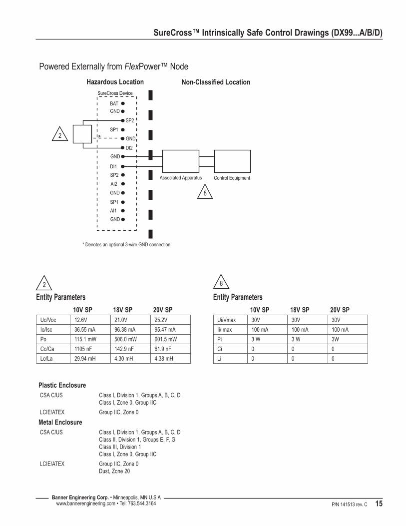
Powered Externally from FlexPower™ Node
Non-Classified Location
Associated Apparatus Control Equipment
* Denotes an optional 3-wire GND connection
*
DI1
GND
SP2
GND
BAT
SP1
DI2
SP2
AI2
GND
SP1
AI1
GND
SureCross Device
GND
8
2
Entity Parameters10V SP 18V SP 20V SP
Uo/Voc 12.6V 21.0V 25.2V
Io/Isc 36.55 mA 96.38 mA 95.47 mA
Po 115.1 mW 506.0 mW 601.5 mW
Co/Ca 1105 nF 142.9 nF 61.9 nF
Lo/La 29.94 mH 4.30 mH 4.38 mH
2
Entity Parameters10V SP 18V SP 20V SP
Ui/Vmax 30V 30V 30V
Ii/Imax 100 mA 100 mA 100 mA
Pi 3 W 3 W 3W
Ci 0 0 0
Li 0 0 0
8
Plastic EnclosureCSA C/US Class I, Division 1, Groups A, B, C, D
Class I, Zone 0, Group IIC
LCIE/ATEX Group IIC, Zone 0
Metal EnclosureCSA C/US Class I, Division 1, Groups A, B, C, D
Class II, Division 1, Groups E, F, G Class III, Division 1 Class I, Zone 0, Group IIC
LCIE/ATEX Group IIC, Zone 0 Dust, Zone 20

Banner Engineering Corp. • Minneapolis, MN U.S.A www.bannerengineering.com • Tel: 763.544.316416 P/N 141513 rev. C
SureCross™ Intrinsically Safe Control Drawings (DX99...A/B/D)
*
Hazardous Location
Powered Externally from FlexPower™ Node
Non-Classified Location
Associated Apparatus Control Equipment
Associated Apparatus Control Equipment
* Denotes an optional 3-wire GND connection
*
DI1
GND
SP2
GND
BAT
SP1
DI2
SP2
AI2
GND
SP1
AI1
GND
SureCross Device
GND
Entity Parameters10V SP 18V SP 20V SP
Ui/Vmax 30V 30V 30V
Ii/Imax 100 mA 100 mA 100 mA
Pi 3 W 3 W 3 W
Ci 0 0 0
Li 0 0 0
8
8
8
4
4
Entity Parameters10V SP 18V SP 20V SP
Uo/Voc 12.6V 21.0V 25.2V
Io/Isc 36.64 mA 96.47 mA 95.56 mA
Po 115.4 mW 506.5 mW 602.0 mW
Co/Ca 552 nF 71.4 nF 30.9 nF
Lo/La 14.9 mH 2.14 mH 2.19 mH
4
Class I, Division 1, Groups A - D Class II, Division 1, Groups E - G Class III, Division 1 ATEX Class I, Zone 0
Plastic EnclosureCSA C/US Class I, Division 1, Groups A, B, C, D
Class I, Zone 0, Group IIC
LCIE/ATEX Group IIC, Zone 0
Metal EnclosureCSA C/US Class I, Division 1, Groups A, B, C, D
Class II, Division 1, Groups E, F, G Class III, Division 1 Class I, Zone 0, Group IIC
LCIE/ATEX Group IIC, Zone 0 Dust, Zone 20

P/N 141513 rev. C 17Banner Engineering Corp. • Minneapolis, MN U.S.A
www.bannerengineering.com • Tel: 763.544.3164
SureCross™ Intrinsically Safe Control Drawings (DX99...A/B/D)
Hazardous Location
Powered Externally from FlexPower™ Node
Non-Classified LocationNon-Classified Location
Associated Apparatus
Associated Apparatus
Control Equipment
Associated Apparatus Control Equipment
Control Equipment
DI1
GND
SP2
GND
GND
BAT
SP1
DI2
SP2
AI2
GND
SP1
AI1
GND
SureCross Device
Associated Apparatus Control Equipment
8
8
8
8
Plastic EnclosureCSA C/US Class I, Division 1, Groups A, B, C, D
Class I, Zone 0, Group IIC
LCIE/ATEX Group IIC, Zone 0
Metal EnclosureCSA C/US Class I, Division 1, Groups A, B, C, D
Class II, Division 1, Groups E, F, G Class III, Division 1 Class I, Zone 0, Group IIC
LCIE/ATEX Group IIC, Zone 0 Dust, Zone 20
Entity Parameters10V SP 18V SP 20V SP
Ui/Vmax 30V 30V 30V
Ii/Imax 100 mA 100 mA 100 mW
Pi 3 W 3 W 3 W
Ci 0 0 0
Li 0 0 0
8

Banner Engineering Corp. • Minneapolis, MN U.S.A www.bannerengineering.com • Tel: 763.544.316418 P/N 141513 rev. C
SureCross™ Intrinsically Safe Control Drawings (DX99...A/B/D)
Thermocouple Nodes
Hazardous Location
A2+
A2−
DI1DI2
A4+
A4−
A3+
A3−
A1+
A1−
A5−A6−
GNDGND
GNDGND
ThermistorInput Wiring
SureCross Device
Thermocouple 2 Thermocouple 1
Thermocouple 3
Sinking Input 1
output
sensor
Sinking Input 2
output
sensor
Entity ParametersUo/Voc 3.9V
Io/Isc 1.20 mA
Po 1.17 mW
Co/Ca 670 μF
Lo/La 27.7 H
9
99
10
1010
11
Entity ParametersUo/Voc 3.9V
Io/Isc 7.88 mA
Po 7.69 mW
Co/Ca 670 μF
Lo/La 644 mH
10
Entity ParametersUo/Voc 3.9V
Io/Isc 68.59 mA
Po 66.88 mW
Co/Ca 670 μF
Lo/La 8.5 mH
11
Plastic EnclosureCSA C/US Class I, Division 1, Groups A, B, C, D
Class I, Zone 0, Group IIC
LCIE/ATEX Group IIC, Zone 0
Metal EnclosureCSA C/US Class I, Division 1, Groups A, B, C, D
Class II, Division 1, Groups E, F, G Class III, Division 1 Class I, Zone 0, Group IIC
LCIE/ATEX Group IIC, Zone 0 Dust, Zone 20

P/N 141513 rev. C 19Banner Engineering Corp. • Minneapolis, MN U.S.A
www.bannerengineering.com • Tel: 763.544.3164
SureCross™ Intrinsically Safe Control Drawings (DX99...A/B/D)
Hazardous Location
A4−
DI2
GND
A4+
GND
DI1
A5
A3+
A3−
A2+
A2−
A1+
A1−
SureCross Device
A6
Sinking Input 2
Sinking Input 1
ThermistorInput Wiring
Thermocouple 2
Thermocouple 3
Thermocouple 1
Entity ParametersUo/Voc 3.9V
Io/Isc 1.20 mA
Po 1.17 mW
Co/Ca 670 μF
Lo/La 27.7 H
9
9
9
10
10
10
11
Entity ParametersUo/Voc 3.9V
Io/Isc 7.88 mA
Po 7.69 mW
Co/Ca 670 μF
Lo/La 644 mH
10
Entity ParametersUo/Voc 3.9V
Io/Isc 68.59 mA
Po 66.88 mW
Co/Ca 670 μF
Lo/La 8.5 mH
11
Plastic EnclosureCSA C/US Class I, Division 1, Groups A, B, C, D
Class I, Zone 0, Group IIC
LCIE/ATEX Group IIC, Zone 0
Metal EnclosureCSA C/US Class I, Division 1, Groups A, B, C, D
Class II, Division 1, Groups E, F, G Class III, Division 1 Class I, Zone 0, Group IIC
LCIE/ATEX Group IIC, Zone 0 Dust, Zone 20
Thermocouple Nodes (DX99...D Housing)

Banner Engineering Corp. • Minneapolis, MN U.S.A www.bannerengineering.com • Tel: 763.544.316420 P/N 141513 rev. C
SureCross™ Intrinsically Safe Control Drawings (DX99...A/B/D)
RTD Nodes
A2+
A2−
DI1
RTD2
RTD4 RTD3
RTD1
DI2
A4+
A4−
A3+
A3−
A1+
A1−
Hazardous Location
A5−A6−
GNDGND
GNDGND
SureCross Device
Entity ParametersUo/Voc 3.9V
Io/Isc 70.1 mA
Po 68.35 mW
Co/Ca 670 μF
Lo/La 8.13 mH
12
12
12
12
12
Plastic EnclosureCSA C/US Class I, Division 1, Groups A, B, C, D
Class I, Zone 0, Group IIC
LCIE/ATEX Group IIC, Zone 0
Metal EnclosureCSA C/US Class I, Division 1, Groups A, B, C, D
Class II, Division 1, Groups E, F, G Class III, Division 1 Class I, Zone 0, Group IIC
LCIE/ATEX Group IIC, Zone 0 Dust, Zone 20

P/N 141513 rev. C 21Banner Engineering Corp. • Minneapolis, MN U.S.A
www.bannerengineering.com • Tel: 763.544.3164
SureCross™ Intrinsically Safe Control Drawings (DX99...A/B/D)
RTD Nodes (DX99...D Housing)
Hazardous Location
RTD4
RTD2
RTD3
RTD1
A4−
DI2
GND
A4+
GND
DI1
A5
A3+
A3−
A2+
A2−
A1+
A1−
SureCross Device
A6
Entity ParametersUo/Voc 3.9V
Io/Isc 70.1 mA
Po 68.35 mW
Co/Ca 670 μF
Lo/La 8.13 mH
12
12
12
12
12
Plastic EnclosureCSA C/US Class I, Division 1, Groups A, B, C, D
Class I, Zone 0, Group IIC
LCIE/ATEX Group IIC, Zone 0
Metal EnclosureCSA C/US Class I, Division 1, Groups A, B, C, D
Class II, Division 1, Groups E, F, G Class III, Division 1 Class I, Zone 0, Group IIC
LCIE/ATEX Group IIC, Zone 0 Dust, Zone 20

Banner Engineering Corp. • Minneapolis, MN U.S.A www.bannerengineering.com • Tel: 763.544.316422 P/N 141513 rev. C
SureCross™ Intrinsically Safe Control Drawings (DX99...A/B/D)
Bridge
A2+
A2−
DI1DI2
A4+
A4−
A3+
A3−
A1+
A1−
A5−A6−
V
GNDGND
GNDGND
V
SureCross Device
Hazardous Location
Bridge supply −
Bridge supply +
Bridgesense −
Bridgesense +
Bridge 1
Bridge supply −
Bridge supply +
Bridgesense −
Bridgesense +
Bridge 2
Sinking Input 1
output
sensor
Sinking Input 2
output
sensor
Entity ParametersUo/Voc 3.9V
Io/Isc 1.20 mA
Po 1.17 mW
Co/Ca 670 μF
Lo/La 27.7 H
9
99
Entity ParametersUo/Voc 3.9V
Io/Isc 98.94 mA
Po 96.47 mW
Co/Ca 670 μF
Lo/La 4.08 mH
13
1313
Plastic EnclosureCSA C/US Class I, Division 1, Groups A, B, C, D
Class I, Zone 0, Group IIC
LCIE/ATEX Group IIC, Zone 0
Metal EnclosureCSA C/US Class I, Division 1, Groups A, B, C, D
Class II, Division 1, Groups E, F, G Class III, Division 1 Class I, Zone 0, Group IIC
LCIE/ATEX Group IIC, Zone 0 Dust, Zone 20

P/N 141513 rev. C 23Banner Engineering Corp. • Minneapolis, MN U.S.A
www.bannerengineering.com • Tel: 763.544.3164
SureCross™ Intrinsically Safe Control Drawings (DX99...A/B/D)
Bridge (DX99...D Housing)
Hazardous Location
Sinking Input 1
Sinking Input 2
A4−
DI2
GND
A4+
GND
DI1
A5
A3+
A3−
A2+
A2−
A1+
A1−
SureCross Device
A6
V
Bridge supply −
Bridge supply +
Bridgesense −
Bridgesense +
Bridge 2
V
Bridge supply −
Bridge supply +
Bridgesense −
Bridgesense +
Bridge 1
Entity ParametersUo/Voc 3.9V
Io/Isc 1.20 mA
Po 1.17 mW
Co/Ca 670 μF
Lo/La 27.7 H
9
9
9
Entity ParametersUo/Voc 3.9V
Io/Isc 98.94 mA
Po 96.47 mW
Co/Ca 670 μF
Lo/La 4.08 mH
13
1313
Plastic EnclosureCSA C/US Class I, Division 1, Groups A, B, C, D
Class I, Zone 0, Group IIC
LCIE/ATEX Group IIC, Zone 0
Metal EnclosureCSA C/US Class I, Division 1, Groups A, B, C, D
Class II, Division 1, Groups E, F, G Class III, Division 1 Class I, Zone 0, Group IIC
LCIE/ATEX Group IIC, Zone 0 Dust, Zone 20

Banner Engineering Corp. • Minneapolis, MN U.S.A www.bannerengineering.com • Tel: 763.544.316424 P/N 141513 rev. C
SureCross™ Intrinsically Safe Control Drawings (DX99...A/B/D)
Bridge and Thermistor
A2+
A2−
DI1DI2
A4+
A4−
A3+
A3−
A1+
A1−
A5−A6−
V
GNDGND
GNDGND
SureCross Device
Hazardous Location
Bridge supply −
Bridge supply +
Bridgesense −
Bridgesense +
Bridge 1
Sinking Input 1
output
sensor
Sinking Input 2
output
sensor
ThermistorInput Wiring
Entity ParametersUo/Voc 3.9V
Io/Isc 1.20 mA
Po 1.17 mW
Co/Ca 670 μF
Lo/La 27.7 H
9
99
Entity ParametersUo/Voc 3.9V
Io/Isc 68.59 mA
Po 66.88 mW
Co/Ca 670 μF
Lo/La 8.5 mH
14
14
Entity ParametersUo/Voc 3.9V
Io/Isc 98.94 mA
Po 96.47 mW
Co/Ca 670 μF
Lo/La 4.08 mH
15
15
Plastic EnclosureCSA C/US Class I, Division 1, Groups A, B, C, D
Class I, Zone 0, Group IIC
LCIE/ATEX Group IIC, Zone 0
Metal EnclosureCSA C/US Class I, Division 1, Groups A, B, C, D
Class II, Division 1, Groups E, F, G Class III, Division 1 Class I, Zone 0, Group IIC
LCIE/ATEX Group IIC, Zone 0 Dust, Zone 20

P/N 141513 rev. C 25Banner Engineering Corp. • Minneapolis, MN U.S.A
www.bannerengineering.com • Tel: 763.544.3164
SureCross™ Intrinsically Safe Control Drawings (DX99...A/B/D)
Bridge and Thermistor (DX99...D Housing)
Hazardous Location
ThermistorInput Wiring
Sinking Input 1
Sinking Input 2
A4−
DI2
GND
A4+
GND
DI1
A5
A3+
A3−
A2+
A2−
A1+
A1−
SureCross Device
A6
V
Bridge supply −
Bridge supply +
Bridgesense −
Bridgesense +
Bridge 1
Entity ParametersUo/Voc 3.9V
Io/Isc 1.20 mA
Po 1.17 mW
Co/Ca 670 μF
Lo/La 27.7 H
9
99
Entity ParametersUo/Voc 3.9V
Io/Isc 68.59 mA
Po 66.88 mW
Co/Ca 670 μF
Lo/La 8.5 mH
14
14
Entity ParametersUo/Voc 3.9V
Io/Isc 98.94 mA
Po 96.47 mW
Co/Ca 670 μF
Lo/La 4.08 mH
15
15
Plastic EnclosureCSA C/US Class I, Division 1, Groups A, B, C, D
Class I, Zone 0, Group IIC
LCIE/ATEX Group IIC, Zone 0
Metal EnclosureCSA C/US Class I, Division 1, Groups A, B, C, D
Class II, Division 1, Groups E, F, G Class III, Division 1 Class I, Zone 0, Group IIC
LCIE/ATEX Group IIC, Zone 0 Dust, Zone 20

Banner Engineering Corp. • Minneapolis, MN U.S.A www.bannerengineering.com • Tel: 763.544.316426 P/N 141513 rev. C
SureCross™ Intrinsically Safe Control Drawings (DX99...A/B/D)
SP2
V-
V-V+
DI2
V-
V-
DI1
SP1
SP1
V-AI2
AI1V-
V+V+
SureCross Device
IS Power Converter Node
AssociatedApparatus
FieldDevice #1
FieldDevice #2
FieldDevice #3
FieldDevice #4
Control Drawings - IS Power Converter Nodes
Entity Parameters
Ui/Vmax 30V
Ii/Imax 100 mA
Pi 750 mW
Ci 48 nF
Li 2.18 mH
Entity Parameters
Uo/Voc 30V
Io/Isc 100 mA
Po 750 mW
Co/Ca 12 nF
Lo/La 0.50 mH
17
Plastic EnclosureCSA C/US Class I, Division 1, Groups A, B, C, D
Class I, Zone 0, Group IIC
LCIE/ATEX Group IIC, Zone 0
Metal EnclosureCSA C/US Class I, Division 1, Groups A, B, C, D
Class II, Division 1, Groups E, F, G Class III, Division 1 Class I, Zone 0, Group IIC
LCIE/ATEX Group IIC, Zone 0 Dust, Zone 20
16
16
17
17
17
17
Line Power Configuration A - 4 V+

P/N 141513 rev. C 27Banner Engineering Corp. • Minneapolis, MN U.S.A
www.bannerengineering.com • Tel: 763.544.3164
SureCross™ Intrinsically Safe Control Drawings (DX99...A/B/D)
SP2
V-
V-V+
DI2
V-
V-
DI1
SP1
SP1
V-AI2
AI1V-
V+V+
SureCross Device
IS Power Converter Node
AssociatedApparatus
FieldDevice #1
FieldDevice #2
FieldDevice #3
FieldDevice #4
Entity Parameters
Ui/Vmax 30V
Ii/Imax 100 mA
Pi 750 mW
Ci 0 nF
Li 0.18 mH
Plastic EnclosureCSA C/US Class I, Division 1, Groups A, B, C, D
Class I, Zone 0, Group IIC
LCIE/ATEX Group IIC, Zone 0
Metal EnclosureCSA C/US Class I, Division 1, Groups A, B, C, D
Class II, Division 1, Groups E, F, G Class III, Division 1 Class I, Zone 0, Group IIC
LCIE/ATEX Group IIC, Zone 0 Dust, Zone 20
18
18
7
7
7
7
Line Power Configuration B - 4 SP

Banner Engineering Corp. • Minneapolis, MN U.S.A www.bannerengineering.com • Tel: 763.544.316428 P/N 141513 rev. C
SureCross™ Intrinsically Safe Control Drawings (DX99...A/B/D)
SP2
V-
V-V+
DI2
V-
V-
DI1
SP1
SP1
V-AI2
AI1V-
V+V+
SureCross Device
IS Power Converter Node
FieldDevice #3
FieldDevice #4
AssociatedApparatus
FieldDevice #1
FieldDevice #2
19
20
20
4
4
Entity Parameters
Ui/Vmax 30V
Ii/Imax 100 mA
Pi 750 mW
Ci 48 nF
Li 2.18 mH
Entity Parameters
Uo/Voc 30V
Io/Isc 100 mA
Po 750 mW
Co/Ca 24 nF
Lo/La 1 mH
2019
Line Power Configuration C - 2 V+, 2SP

P/N 141513 rev. C 29Banner Engineering Corp. • Minneapolis, MN U.S.A
www.bannerengineering.com • Tel: 763.544.3164
SureCross™ Intrinsically Safe Control Drawings (DX99...A/B/D)
Watertight Glands and Plugs
If the Gateway or Node is mounted outdoors or will be exposed to moisture, dirt, or dust, follow these steps to weatherproof the units.
Watertight GlandsTo make the glands watertight:
Wrap four to eight passes of polytetrafluoroethylene (PTFE) tape 1. around the threads as close as possible to the hexagonal body of the gland.
Manually thread the gland into the housing hole. Never apply 2. more than 5 in-lbf of torque to the gland or its cable clamp nut.*
Note, these instructions apply both to the PG-7 glands and the 1/2” NPT gland.
Watertight PG-7 PlugSeal any unused PG-7 access holes with one of the supplied black plastic plugs. To install a watertight PG-7 plug:
Wrap four to eight passes of PTFE tape around the plug’s 1. threads, as close as possible to the flanged surface.
Carefully thread the plastic plug into the vacant hole in the DX80 2. housing and tighten using a slotting screwdriver. Never apply more than 10 in-lbf torque to the plastic plug.
Weather-Proofing Glands and Plugs
Rotary Switch Access CoverCheck the rotary switch access cover o-ring every time the access cover is removed. Replace the o-ring when it is damaged, discolored, or showing signs of wear. The o-ring should be:
Seated firmly against the threads without stretching to fit or • without bulging loosely, and
Pushed against the flanged cover.•
When removing or closing the rotary switch access cover, manually twist the cover into position. Do not allow cross-threading between the cover and the DX80 face.
Once the cover is in place and manually tightened, use a small screwdriver (no longer than five inches total length) as a lever to apply enough torque to bring the rotary switch access cover even with the DX80 cover surface.
Watertight 1/2” NPT PlugSeal the 1/2” NPT port if it is not used. To install a watertight NPT plug:
Wrap 12 to 16 passes of PTFE tape evenly across the length of 1. the threads.
Manually thread the plug into the housing port until reaching 2. some resistance.
Using a 9/16” crescent wrench, turn the plug until all the plug’s 3. threads are engaged by the housing port or until the resistance doubles. Do not overtighten as this will damage the SureCross unit. These threads are tapered and will create a waterproof seal without overtightening.
* This is not a lot of torque and is equivalent to the torque generated without using tools. If a wrench is used, apply only very light pressure. Torquing these fittings excessively damages the device.

Banner Engineering Corp. • Minneapolis, MN U.S.A www.bannerengineering.com • Tel: 763.544.316430 P/N 141513 rev. C
SureCross™ Intrinsically Safe Control Drawings (DX99...A/B/D)
To replace the lithium “D” cell battery in the DX81H FlexPower™ battery kit,
Unplug the battery device from the SureCross device it powers.1.
Remove the four screws mounting the battery pack face plate to the 2. body and remove the face plate.
Remove the discharged battery and replace with a new battery. 3. Only use a 3.6V lithium battery from Xeno, model number XL-205F.
Verify the battery’s positive and negative terminals align to the 4. positive and negative terminals of the battery holder mounted within the case. The negative end is toward the spring. Caution: There is a risk of explosion if the replacement battery is incorrect.
After replacing the battery, allow up to 60 seconds for the device to 5. power up.
When removing the battery, press the battery towards the negative terminal to compress the spring. Pry up on the battery’s positive end to remove from the battery holder. Properly dispose of your used battery according to local regulations by taking it to a hazardous waste collection site, an e-waste disposal center, or other facility qualified to accept lithium batteries.
As with all batteries, these are a fire, explosion, and severe burn hazard. Do not burn or expose them to high temperatures. Do not recharge, crush, disassemble, or expose the contents to water.
DX81H Battery Replacement
Warning: Explosions may result in death or serious injury. Do not remove the instrument cover or open the wiring housing in explosive atmospheres when power and communications are on. Remove the battery-powered device from the hazardous location before opening the cover and replacing the battery.
Warning: The replacement battery MUST be a Banner approved battery, model number BWA-BATT-001. Use of a different battery will VOID the intrinsic safety rating of this device and may result in an explosion!
Warning: When replacing the battery, the negative end of the battery holder is the side with the spring terminal. This side is marked with a minus (−) sign.
Warning: Do not attempt to recharge the battery. These batteries are not rechargeable. Recharging may cause serious injury to personnel or damage the equipment. Replace only with factory recommended batteries.
P/N 141513 rev. C 31Banner Engineering Corp. • Minneapolis, MN U.S.A
www.bannerengineering.com • Tel: 763.544.3164
SureCross™ Intrinsically Safe Control Drawings (DX99...A/B/D)
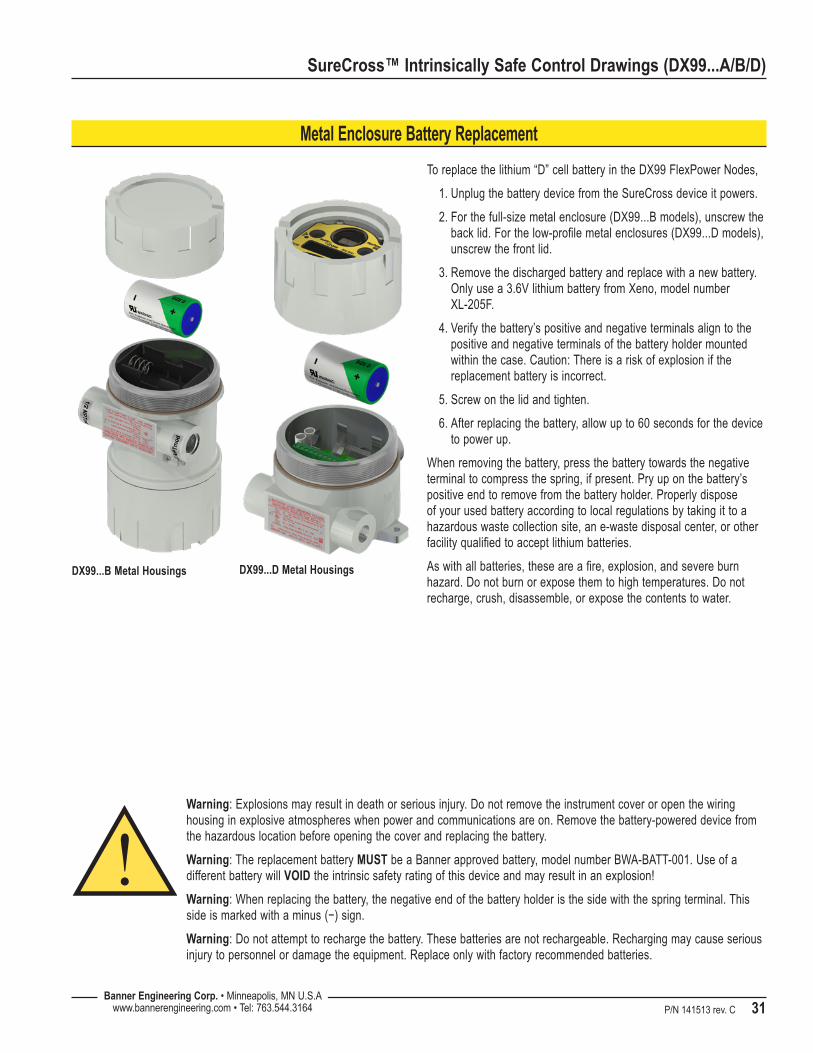
Metal Enclosure Battery Replacement
To replace the lithium “D” cell battery in the DX99 FlexPower Nodes,
Unplug the battery device from the SureCross device it powers.1.
For the full-size metal enclosure (DX99...B models), unscrew the 2. back lid. For the low-profile metal enclosures (DX99...D models), unscrew the front lid.
Remove the discharged battery and replace with a new battery. 3. Only use a 3.6V lithium battery from Xeno, model number XL-205F.
Verify the battery’s positive and negative terminals align to the 4. positive and negative terminals of the battery holder mounted within the case. Caution: There is a risk of explosion if the replacement battery is incorrect.
Screw on the lid and tighten.5.
After replacing the battery, allow up to 60 seconds for the device 6. to power up.
When removing the battery, press the battery towards the negative terminal to compress the spring, if present. Pry up on the battery’s positive end to remove from the battery holder. Properly dispose of your used battery according to local regulations by taking it to a hazardous waste collection site, an e-waste disposal center, or other facility qualified to accept lithium batteries.
As with all batteries, these are a fire, explosion, and severe burn hazard. Do not burn or expose them to high temperatures. Do not recharge, crush, disassemble, or expose the contents to water.
Warning: Explosions may result in death or serious injury. Do not remove the instrument cover or open the wiring housing in explosive atmospheres when power and communications are on. Remove the battery-powered device from the hazardous location before opening the cover and replacing the battery.
Warning: The replacement battery MUST be a Banner approved battery, model number BWA-BATT-001. Use of a different battery will VOID the intrinsic safety rating of this device and may result in an explosion!
Warning: When replacing the battery, the negative end of the battery holder is the side with the spring terminal. This side is marked with a minus (−) sign.
Warning: Do not attempt to recharge the battery. These batteries are not rechargeable. Recharging may cause serious injury to personnel or damage the equipment. Replace only with factory recommended batteries.
DX99...B Metal Housings DX99...D Metal Housings

Banner Engineering Corp., 9714 Tenth Ave. No., Minneapolis, MN USA 55441 • Phone: 763.544.3164 • www.bannerengineering.com • Email: [email protected]
SureCross™ Intrinsically Safe Control Drawings (DX99...A/B/D)
P/N 141513 rev. C
The manufacturer does not take responsibility for the violation of any warning listed in this document.
CAUTION. Make no modifications to this product. Any modifications to this product not expressly approved by Banner Engineering could void the user’s authority to operate the product. Contact the Factory for more information.
Lightning Arrestors/Surge Protection. Always use lightning arrestors/surge protection with all remote antenna systems to avoid invalidating the Banner Engineering Corp. warranty. No surge protector can absorb all lightning strikes. Do not touch the SureCross device or any equipment connected to the SureCross device during a thunderstorm.
WARRANTY. Banner Engineering Corp. warrants its products to be free from defects for one year. Banner Engineering Corp. will repair or replace, free of charge, any product of its manufacture found to be defective at the time it is returned to the factory during the warranty period. This warranty does not cover damage or liability for the improper application of Banner products. This warranty is in lieu of any other warranty either expressed or implied.
All specifications published in this document are subject to change. Banner reserves the right to modify the specifications of products, prior to their order, without notice. Banner Engineering reserves the right to update or change documentation at any time. For the most recent version of any documentation, please refer to our website: www.bannerengineering.com. © 2009-2010 Banner Engineering Corp. All rights reserved.