surface matrix based machining planes determination for
TRANSCRIPT

Surface matrix based Machining Planes Determination for Milling Process (Roughing Stage)
Dr. Laith A. Mohammed*
Published in J. of Engineering and Technology, University of Technology, Baghdad, Iraq, Vol.25, No.2, 2007, pp.153-167
Abstract This paper deals with machining planes determination process for CNC milling machining. Three methods, Matrix, 3D contour matrix and flow line are presented. All methods depend on the data set point of the surface matrix of the workpiece to be machined. All methods can be used to automate the CAD/CAM operation for roughing process in milling machining. Two surface examples are included to illustrate all methods. By a comparison among the three presented methods, a conclusion has been reached that the presented 3D contour matrix method requires maximum number of blocks to build G-codes program for CNC tool path programming. It means that, this method requires longer time to accomplish tool paths. While the other two methods require minimum number of blocks of G-codes and shorter time for roughing. Keywords: CAD/CAM, CNC Milling, Sculptured surfaces Introduction: In the manufacturing industry, the production cost of a part depends largely on the part's machining time. Machining parameters, such as cutters and machining planes, are typically selected to reduce the machining time and to prolong tool life. Due to the combinational nature, it has been proven to be very difficult for manufacturing engineers to select cutters and determine machining planes (1-4). Because any reduction in the machining time can be directly translated into savings in production cost, it is of interest to manufacturing engineers to study such a problem (5). Most commercial CAD/CAM systems today are feature-based, and their use involves considerable operator effort and experience (6). In this paper, it has been shown useful approaches to prepare tool path machining planes for roughing milling machining process. Instead of decomposing the shape into
manufacturing features (7), it is possible to generate tool paths directly from the shape of workpiece using surface matrix definition of workpiece. The machining of sculptured surface consists of the roughing and finishing processes. Roughing is to remove excess material from a raw stock, while finishing is to remove residual material along the surface after roughing is applied. In general, the removal volume in roughing is more than the removal volume in finishing. Thus, the reduction in roughing time can considerably increase productivity, which, in turn, leads to a lower manufacturing cost (8). Therefore, this paper concentrates on the roughing stage of machining. To increase the efficiency of the roughing process, one could select the largest cutter to work on a machining plane with the cutter's maximal depth, however, due to the nature of sculptured surfaces, different machining planes have different
* Dept. of Production & Metallurgy Eng., University of Technology, Baghdad-IRAQ. - 1 -

Eng. & Technology, Vol., No., Surface matrix based Machining Planes Determination for Milling Process (Roughing Stage)
boundary contours that limit the choice of cutters. This paper utilizes the surface's matrix to generate machining planes with different resolutions that, in turn, helps for applying different cutter size and shapes. Assuming that the part is already oriented in a given setup direction, all methods to global roughing are based on slicing the component into a number of layers directly from the boundary representation, slices are generated as sequences of closed contours. Then generate 2-axis tool paths using the coordinates of points, which construct each layer. The tool paths go along the intersection curves between the surfaces and a series of parallel planes. Fig.(1) shows the main algorithm of applied methods. In this paper, there are three methods prepared to accomplish the roughing milling process. These are, matrix, 3D contour matrix and flow line oriented roughing methods. Matrix Oriented Roughing:
Tool path generation for roughing could be established using either lines of rows or columns of the matrices XYZ for the workpiece surface, through the representation of heights of Z matrix as X, and rows of Z matrix as Y. Rouging is mostly done on parallel layers until a certain depth and uses high metal removal rates, therefore this approach helps to rough the workpiece surface and facilitate using flat end mill cutter and shorting the G-codes program.
The math form, equation (1), of this method, (9), is based on construction of bilinear curves using interpolation of line segment:
)()()()(
21
1
21
1
tptptptp
tttt
−−
=−−
Q
))(())()()(())((
212
1111
tttptptptttttp
−=−−−−
))(()()()()( 212112 tttptptttptt −=−+−
)1.()....()()( 212
11
12
2 eqtptttttp
tttttp
−−
+−−
=∴
where: p(t1), p(t2): end points for line segment. p(t): interpolated point. t: parametric variable.
3D Contour Matrix Oriented Roughing:
The creation of 3D contour matrix and column vector of surface could be defined on a rectangular grid, and produce contour map with nth contour levels, which also can be used as tool path lines for finishing process. Finishing process is made by tracing curves or contours on the surface as accurately and precisely as possible with limitation set by the cutter size tolerance and machine capability. The number of contour levels can be changed with the demand for accuracy of the surface. The contouring function treats the input matrix as a regularly spaced grid, with each element connected to its nearest neighbors. To calculate the contour matrix, the algorithm scans input matrix comparing the values of each block of four neighboring elements (i.e. cell) in the matrix with the contour level values. If contour level falls within the cell, the algorithm performs a linear interpolation to locate the point at which the contour crosses the edge of the cell. The algorithm connects these points to produce a segment of contour line. To determine the heights of the contour lines with respect to a plane, the algorithm produces two-row matrix specifying all the contour lines. Each contour line defined in this matrix begins with a column that contains the value of the contour, and the number of (x,y) vertices in the contour line. Fig.(2) shows the basic contouring algorithm.
- 2 -
Eng. & Technology, Vol., No., Surface matrix based Machining Planes Determination for Milling Process (Roughing Stage)
The math form of this method, (10), is based on considering the surface plotted on rectangular grid in u-w plane, taking values in three space, eq.(2):
)2.(.................)1(
)1(33
),(
,3
33
0,
eqPw
wuuji
wuS
jii
iii
ji
−
−
=
−
−⎟⎟⎠
⎞⎜⎜⎝
⎛⎟⎟⎠
⎞⎜⎜⎝
⎛= ∑
where: )3,0( ≤≤ ji
]1,0[, ∈wu Pi,j : control points of the surface S(u,w). Flow Line Oriented Roughing:
This method is useful to generate tool path for 3D roughing process. In three axes sculptured surface machining the usual procedure is to determine cutter paths by indexing along the u-w parameters of parametrically defined surface, see fig.(3). The tool follows the natural parametric flow lines of the surface.
The math form of this method, (9), is based on cubic Bezier curve for each flow line, equation (3):
)3.(...........)()(0
, equBpupn
inii∑
=
=
where: ini
ni uuini
nuB −−−
= )1()!(!
!)(,
]1,0[∈u n = number of control points. p0, pn : end points for curve segment.
This method would be simple to
use if the entire surface consist of a single patch, see fig.(4). If the part consists of many patches this creates the possibility of accidentally gouging adjacent patches. Results and Discussion:
To review the methods followed in the previous sections, two models drawn in a CAD system, fig.(5), fig.(6), have been taken. The data set for both models have been shown in table (1), (2)
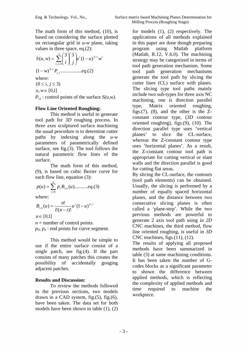
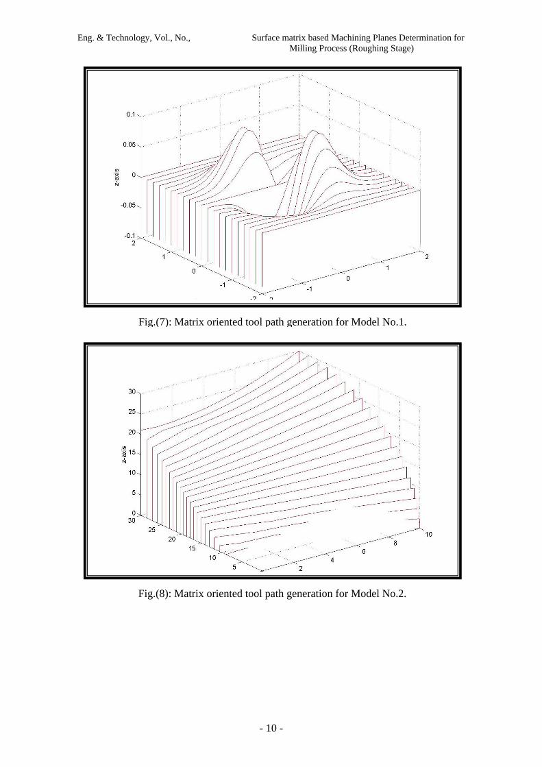
for models (1), (2) respectively. The applications of all methods explained in this paper are done though preparing program using Matlab platform (Matlab, R.12, V.6.0). The machining strategy may be categorized in terms of tool path generation mechanism. Some tool path generation mechanisms generate the tool path by slicing the cutter lines (CL) surface with planes. The slicing type tool paths mainly include two sub-types for three axis NC machining, one is direction parallel type, Matrix oriented roughing, figs.(7), (8), and the other is the Z-constant contour type, (3D contour oriented roughing), figs.(9), (10). The direction parallel type uses ‘vertical planes’ to slice the CL-surface, whereas the Z-constant contour type uses ‘horizontal planes’. As a result, the Z-constant contour tool path is appropriate for cutting vertical or slant walls and the direction parallel is good for cutting flat areas. By slicing the CL-surface, the contours (tool path elements) can be obtained. Usually, the slicing is performed by a number of equally spaced horizontal planes, and the distance between two consecutive slicing planes is often called a ‘plane-step’. While the two previous methods are powerful to generate 2 axis tool path using in 2D CNC machines, the third method, flow line oriented roughing, is useful in 3D CNC machines, figs.(11), (12). The results of applying all proposed methods have been summarized in table (3) at same machining conditions. It has been taken the number of G-codes blocks as a significant parameter to shown the difference between applied methods, which is reflecting the complexity of applied methods and time required to machine the workpiece.
- 3 -

Eng. & Technology, Vol., No., Surface matrix based Machining Planes Determination for Milling Process (Roughing Stage)
Conclusion: In this paper, three methods have
been presented to solve the machining plane determination problem. Each method has its significant impact to reduce the total machining time for roughing process in milling machining.
From table (3), 3D contour matrix oriented roughing method requires the biggest number of blocks to accomplish the required shape. This means the smoothest roughing resultant surface can be obtained from the 3D contour method than the others. While Flow Line Oriented Roughing method represents the easiest (less number of G-codes blocks) and fastest (less required time for roughing) way to accomplish the roughing process. So that, it could be concluded that, in spite of considering roughing process as pre machining step before finishing step, applying the presented methods makes a significant change in both criterions of machining, i.e. quality of machined surface and time required to machining. 3D contour matrix oriented roughing method could satisfy an acceptable demand of quality for the machined surface and preparing the surface to fast post finishing process. While the other two presented methods, matrix and flow line oriented roughing; reflect the major role of roughing which is fast machining and preparing the workpiece to finishing process. So that all presented methods could enhance the manufacturing process though minimizing the overall time required for machining.
This paper shows the importance of using matrix map description of the surface for representing both workpiece profile and tool paths. This kind of representation can be used later to simulate the process of machining, and to enhance verification process through graphical simulation, which depends mainly on matrix representation of workpiece surface. Another benefit of
implementing these methods is easily providing all tool path points which in turn control cutting tool movements. The applied three methods can be used to approximate any class of tool paths, i.e. linear or nonlinear, because their dependency is on point data set of the surface to be machined.
References: 1. T.C.Change, "Computer-Aided Manufacturing", Prentice-Hall, 1991 2. L.Ahing and et.al., "Computer-Aided Process Planning: The state-of-the-art survey", Int.J.of Production Research, Vol.27, No.4, pp.553-585, 1989 3. N.F.Choong, "The implementation of an automatic tool selection system for CNC Nibbling", Computers in Industry, Vol.23, pp. 205-222, 1993 4. Y.S.Lee, "CASCAM- An automated system for sculptured surface cavity machining", Computers in Industry, Vol.16, No.4, pp. 321-342, 1991 5. T.A.Feo, "The cutting path and tool selection problem in computer aided process planning", J. of Mfg. Systems, Vol.8, No.1, pp. 17-26, 1989 6. J.Y.Jung and et.al., "Feature-based non cutting tool path selection", J. of Mfg. Systems, Vol.13, No.3, pp. 165-176, 1994 7. G.Sun and et.al., "Operation decomposition for freeform surface features in process planning", Proceedings of the 1999 ASME Design Eng. Technical Conferences, 1999. 8. Y.H.Chen and et.al., "Optimal cutter selection and machining plane determination for process planning and NC machining of complex surfaces", J. of Mfg. Systems, Vol.17, No.5, pp. 371-388, 1998 9. Foley, J. D., van Dam, A., Feiner, S.
K ., Hughes, J. F., and Philips, R. L., "Introduction to Computer Graphics", Addison-Wesley Publishing Company, Ontario, 1994.
- 4 -

Eng. & Technology, Vol., No., Surface matrix based Machining Planes Determination for Milling Process (Roughing Stage)
10. Colm Mulcahy, "The Basic Curves and Surfaces of Computer Aided Geometric Design", Department of
Mathematics, Spelman College, Atlanta,USA, pp.4, http://www.auc.edu/~colm.
- 5 -

Eng. & Technology, Vol., No., Surface matrix based Machining Planes Determination for Milling Process (Roughing Stage)
Workpiece surface as X,Y,Z matrices
Matrix Oriented Roughing
A list of sliced 2D contours which define machining planes
3D Contour Matrix Oriented Roughing
Flow Line Oriented Roughing
Linear Interpolation
Rearrange 3D data set on rows to construct mesh
Divide the height of workpiece (Z) into number of stages
according to contour values extracting from
3D contour matrix, each stage represent part of
total depth of cut
Drawing reference plane around the
mesh
3D interpolated curves
Fig.(1): Block diagram for the applied methods for the machining planes determination process for CNC milling machining (Roughing stage).
- 6 -

Eng. & Technology, Vol., No., Surface matrix based Machining Planes Determination for Milling Process (Roughing Stage)
Fig.(2): Basic contouring algorithm
- 7 -

Eng. & Technology, Vol., No., Surface matrix based Machining Planes Determination for Milling Process (Roughing Stage)
w
u
w
u
Fig.(3): u-w parameters of parametrically defined surface patch.
Fig.(4): Representation of surface patch.
- 8 -

Eng. & Technology, Vol., No., Surface matrix based Machining Planes Determination for Milling Process (Roughing Stage)
Fig.(5): Surface Representation of Model No.1.
Fig.(6): Surface Representation of Model No.2.
- 9 -
Eng. & Technology, Vol., No., Surface matrix based Machining Planes Determination for Milling Process (Roughing Stage)
Fig.(7): Matrix oriented tool path generation for Model No.1.
Fig.(8): Matrix oriented tool path generation for Model No.2.
- 10 -

Eng. & Technology, Vol., No., Surface matrix based Machining Planes Determination for Milling Process (Roughing Stage)
Fig.(9): 3D contour plot for Model No.1. [Number of contours = 30]
Fig.(10): 3D contour plot for Model No.2. [Number of contours = 40]
- 11 -

Eng. & Technology, Vol., No., Surface matrix based Machining Planes Determination for Milling Process (Roughing Stage)
Fig.(11): Flow line machining paths for Model No.1.
Fig.(12): Flow line machining paths for Model No.2.
- 12 -

Eng. & Technology, Vol., No., Surface matrix based Machining Planes Determination for Milling Process (Roughing Stage)
Table (1): Sample of Data set for Model No.1 Array X {size 21x41}
Array Y {size 21x41}
Array Z {21x41}
- 13 -

Eng. & Technology, Vol., No., Surface matrix based Machining Planes Determination for Milling Process (Roughing Stage)
Table (2): Sample of Data set for Model No.2 Array X {size 21x11}
Array Y {size 21x11}
Array Z {size 21x11}
- 14 -

Eng. & Technology, Vol., No., Surface matrix based Machining Planes Determination for Milling Process (Roughing Stage)
Table (3): Comparison between the applied methods with respect to number of G-codes
blocks and time required for roughing, at same machining conditions.
Number of G-codes blocks
(time required for roughing in minutes)
Surface matrix based machining Method
Model No.1 Model No.2
Matrix Oriented Roughing 904
(52)
388
(47)
3D Contour Matrix Oriented Roughing 17826
(70)
20588
(84)
Flow Line Oriented Roughing 802
(30)
269
(22)
[Machining Conditions: Spindle speed = 9549 rpm, Feed rate= 1146 mm/min, Ball nose
mill cutter, Tool diameter = 1 mm, Tip radius= 0.5 mm, Tool material= High Speed
Steel, Workpiece material= Steel St33]
- 15 -