surface mine electrician - utah labor commission
TRANSCRIPT

Test Preparation Study Guide for
Coal Mine Certification
SURFACE MINE ELECTRICIAN

1
Test Preparation Study Guide For
Coal Mine Electrical Certification
SURFACE ELECTRICIAN
This guide was developed for the Utah Labor Commission by Bruno Engineering, Price, Utah.

2
TABLE OF CONTENTS SURFACE ELECTRICIAN
Section Page Preface 3 Test #1 - DC Theory and Application 6 Test #1 - DC Theory and Application Sample Questions 24 Test #1 - DC Theory and Application Answer Sheet 32 Test #2 - AC Theory and Application 33 Test #2 - AC Theory and Application Sample Questions 55 Test #2 - AC Theory and Application Answer Sheet 63 Test #3 - Electric Circuits and Equipment 64 Test #3 - Electric Circuits and Equipment Sample Questions 82 Test #3 - Electric Circuits and Equipment Answer Sheet 94 Test #4 - Permissibility of Electrical Equipment 97 Test #4 - Permissibility of Electrical Equipment Sample Questions 103 Test #4 - Permissibility of Electrical Equipment Answer Sheet 111 Test #5 - Mine Law - 30 CFR, Part 77 (Surface) 112 Test #5 - Mine Law - 30 CFR, Part 77 (Surface) Sample Questions 116 Test #5 - Mine Law - 30 CFR, Part 77 (Surface) Answer Sheet 125 Test #6 - National Electrical Code 126 Test #6 - National Electrical Code Sample Questions 150 Test #6 - National Electrical Code Answer Sheet 156 Test #7 - Practical 157 Test #7 - Practical Examination Sample Test 159

3
Preface
The Code of Federal Regulations, under authority of the Federal Coal Mine Health and Safety Act of 1969 (Public Law 91-173) states that “all electrical equipment shall be frequently examined, tested, and properly maintained by a qualified person to insure safe operating conditions.” An individual may become qualified as a surface coal mine electrician as indicated below:
77.103 Electrical work; qualified person.
(a) Except as provided in paragraph (f) of this section, an individual is a qualified person within the meaning of Subparts F, G, H, I, and J of this Part 77 to perform electrical work (other than work on energized surface high-voltage lines) if:
(1) He has been qualified as a coal mine electrician by a State that has a coal mine electrical qualification program approved by the Secretary; or,
(2) He has at least 1 year experience in performing electrical work underground in a coal mine, in the surface work areas of an underground coal mine, in a surface coal mine, in a non-coal mine, in the mine manufacturing industry, or in any other industry using or manufacturing similar equipment, and has satisfactorily completed a coal mine electrical training program approved by the Secretary; or,
(3) He as at least 1 year of experience, prior to the date of application required by paragraph (c) of this section, in performing electrical work underground in a coal mine, in the surface work areas of an underground coal mine, in a surface coal mine, in a non-coal mine, in the mine equipment manufacturing industry, or in any other industry using or manufacturing similar equipment, and he attains a satisfactory grade on each of the series of five written tests approved by the Secretary as prescribed in paragraph (b) of this section.
(b) The series of five written tests approved by the Secretary shall include the following categories:
(1) Direct current theory and application; (2) Alternating current theory and application; (3) Electric equipment and circuits; (4) Permissibility of electric equipment; and, (5) Requirements of Subparts F through J and S of this Part 77.
(c) In order to take the series of five written tests approved by the Secretary, an individual shall apply to the District Manager and shall certify the he meets the requirements of paragraph (a)(3) of this section. The tests will be administered in the Coal Mine Safety and Health Districts at regular intervals or as demand requires.
(d) A score of at least 80 percent on each of the five written tests will be deemed a satisfactory grade. Recognition shall be given to practical experience in that 1 percentage point shall be added to an individual’s score in each test for each addition year of experience beyond the 1 year requirement specified in paragraph (a)(3) of this section; however, in no case shall an individual be given more than 5 percentage points for such practical experience.
(e) An individual may, within 30 days from the date on which he received notification from the Administration of his test scores, repeat those on which he received an unsatisfactory score. If further retesting is necessary after this initial repetition, a minimum of 30 days from the date of receipt of notification of the initial retest scores shall elapse prior to such further retesting.
(f) An individual who has, prior to November 1, 1972, been qualified to perform electrical work specified in Subparts F, G, H, I, and J of this Part 77 (other than work on energized

4
surface high-voltage lines) shall continue to be qualified until June 30, 1973. To remain qualified after June 30, 1973, such individual shall meet the requirements of either subparagraph (1), (2), or (3) of paragraph (a) of this section.
(g) An individual qualified in accordance with this section shall, in order to retain qualification, certify annually to the District Manager wherein he is employed, that he has satisfactorily completed a coal mine electrical retraining program approved by the Secretary.
77.104 Repair of energized surface high voltage lines; qualified person.
An individual is a qualified person within the meaning of § 75.704 for the purpose of repairing energized surface high voltage lines only if he has had at least 2 years experience in electrical maintenance, and at least 2 years experience in the repair of energized high voltage surface lines located on poles or structures.
This study guide has been prepared for the Utah Labor Commission specifically to provide guidance for those individuals who desire to prepare themselves for Federal qualifications as mine electricians by taking the Utah State Coal Mine Electrician Examination by Bruno Engineering, Price Utah. The Utah State Coal Mine Electrician qualification program has been approved by MSHA. This study guide is not intended to serve as the sole source of preparation, but rather as a tool toward that end.

5
The study guide is divided into sections for each testing category for surface coal mine electrician qualification. The specific sections are listed below and a set of typical examination questions are provided for each section. Also, in each test category an outline is provided which gives topics that are to be tested on in the category. Test #1 - DC Theory and Application Test #2 - AC Theory and Application Test #3 - Electric Circuits and Equipment Test #4 - Permissibility if Electric Equipment Test #5 - Mine Law 30 CFR Part 75 (Surface) Test #6 - National Electric Code Practical - Prints and Meters

6
TEST #1
DC THEORY AND APPLICATION

7
UTAH MINE ELECTRICIAN CERTIFICATION EXAMINATION STUDY GUIDE
I. Test #1 – DC Theory and Application Outline
A. Definitions 1. Semiconductors 2. Electric Current 3. Direct Current 4. Conventional Current Flow 5. Electronic Current Flow 6. Voltage 7. Electromagnetism 8. Rectifier 9. Diode
B. Ohm’s Laws 1. Applied to Series DC Circuits
a. Total circuit current b. Total circuit resistance c. Voltage drop across each series resistor
2. Applied to Parallel DC Circuits a. Total circuit current b. Equivalent or total circuit resistance c. Voltage drop across each parallel resistor
C. Power Formula 1. Total power consumed by the circuit
a. Series circuits b. Parallel circuits
2. Power dissipated by individual resistors a. Series circuits b. Parallel circuits
D. Battery Connections and Resulting Voltage 1. Series 2. Parallel 3. Series-Parallel
E. DC Motors 1. Operating characteristics of various types of DC motors
a. Series b. Shunt c. Compound
2. Connections of various types of DC motors a. Series b. Shunt c. Compound

8
3. Typical symptoms of low voltage applied to DC motors 4. Methods of changing the rotation of DC motors
F. DC Equipment Grounding Methods (Shuttle Cars) 1. Diode 2. Third wire (separate frame ground conductor)
G. DC Motor HP to KW Conversion 1. 0.746 KW = 1 HP 2. 746 W = 1 HP

9
THE ELECTRON THEORY Atomic Structure The modern explanation of electricity is by means of the electron theory, which is based upon the atomic structure if matter. Practically everything around us occupies space and has weight. We call these things matter. All matter is composed of tiny particles called molecules. Matter can be further broken down into fundamental constituents called elements, the tiniest particles of which are called atoms. An atom is the smallest particle of an element that shows its chemical and physical properties. A molecule is the smallest combination of atoms that form a compound of various elements. For a better understanding of the relationship between atoms, molecules, and elements, I will use the example of the water molecule shown in Figure 1.1.
Figure 1.1 – Illustration of a water (H2O) Molecule. Note that the water molecule is composed of two hydrogen atoms and one oxygen atom. Hence the chemical formula for water is H2O. Hydrogen and oxygen are also elements. There are 98 known elements, of which 92 occur in nature and six are artificially produced in atom smashers and nuclear reactors. Since there are 98 elements, there must be 98 different types of atoms. The most widely accepted theory on atomic structure is Bohr’s theory. According to Bohr’s theory, atoms actually have a complex structure, resembling somewhat a miniature solar system. An atom consists of a central nucleus of positive charge around which tiny, negatively charged particles, called electrons, revolve in fixed orbits, just as the planets revolve around the sun. In each type of atom, the negative charge of all the orbital electrons just balances the positive charge of the nucleus, thus making the combination electrically neutral. The positively charged nucleus is made up of two fundamental particles known as the proton and neutron. The proton is a relatively heavy particle (1840 times heavier than the electron) with a positive (+) charge, while the neutron has about the same mass as the proton, but has no charge at all. The positive charge on each proton is equal to the negative charge residing on each electron. Since atoms are electrically neutral, the number of protons in the nucleus is equal to the number of electrons revolving around the nucleus. A diagram of the Bohr model of the hydrogen atom is shown in Figure 1.2.

10
Figure 1.2 – Bohr model of a hydrogen atom.
TABLE 1
Particle Charge Weight Electron -1 1/1840 Proton +1 1 Neutron 0 1 All atoms are made up of protons, neutrons, and electrons. The difference between various elements results from the number and arrangement of the protons, neutrons, and electrons within their atoms. The elements are arranged according to their atomic number, which is equal to the number of electrons revolving around the nucleus. Thus an atom of hydrogen has a single electron spinning around its nucleus, while an atom of uranium has 92 electrons spinning about the nucleus. The orbits of these electrons are arranged in “shells” about the nucleus, each shell having a definite maximum capacity of electrons. The capacity of successive shells from the nucleus out is 2,8,18, and 32 electrons; however, the outermost shell contains never more then eight electrons. It is this outermost shell which determines the chemical valence of an atom and its principle physical characteristics. The outermost shell is also the most important for electricity, since it is the only one from which electrons are relatively easily dislodged to become “free” electrons capable of carrying a current in a conductor. The electrons in the inner shells cannot be forced out easily from their orbits and, hence, are said to be “bound” to the atom. Free Electrons Electrons that have become dislodged from the outer shell of an atom are known as free electrons. These electrons can exist by themselves outside the atom, and it is these free electrons which are responsible for most electrical and electronic phenomena. Free electrons carry the current in ordinary conductors, as well as in all types of electron tubes and semiconductors. Insulators and Conductors “Conductors” are materials that have free electrons; those having tightly bound electrons are classed as “insulators”. It seems that the atoms of most metals are loosely hung together, or they have many free electrons. That is, the attraction between the electrons and the nucleus is weak, and it is easy to push out electrons. In other words, most metals have low resistances and are called good

11
conductors. Most non-metals are just the opposite of this; they have tight atoms which have few free electrons, they are extremely poor conductors and are called insulators. We cannot classify all substances as either conductors or insulators. There is no sharp dividing line. Electricians simply use the best conductors for wires or cables to carry current, and the poorest conductors for insulators to prevent the passage of current. Below is a table listing some of the better conductors and insulators (poorest conductors).
Conductors Insulators Gold Dry air Silver Glass Copper Mica Mercury Plastic Iron Rubber Aluminum Asbestos Brass Paraffin Zinc Dry wood Carbon Oil (only certain types) Electric Current The free electrons in a conductor are ordinarily in a state of chaotic motion in all possible directions. But when an electromotive force (emf) or voltage, such as that provided by a battery is connected across a conductor, the free electrons are guided in an orderly fashion, atom to atom from the negative terminal of the battery, through the wire, to the positive terminal of the battery. This orderly drifting motion of free electrons under the application of an electromotive force constitutes an electric current. Although the electrons drift through the wire at a relatively low speed, the impulse is transmitted almost at the speed of light. Note that the electron current continues to flow only as long as the wire remains connected the battery. The wire itself remains electrically neutral, since electrons are neither gained nor lost by the atoms within the wire. Thus, the free electrons present within the wire act simply as current carriers, which are continually being replaced, but none are lost. Refer to Figure 1.3 for an illustration of current flow through a conductor. Figure 1.3 - Conduction of electricity through a conductor. Until recently it was believed that current flows from positive to negative, which is conventional current flow as it is shown is Figure 1.3. It has since been proven that current flows from negative to positive, which is also shown in Figure 1.3. Although conventional current has been widely used in the markings of meters, formulation of electrical rules, and in many textbooks, we shall not use it as our standard. From now on the term “current” designates electron flow from negative (-) to positive (+).
12
ELECTRICAL SOURCES The chief sources of electricity are mechanical, chemical, photoelectric, thermoelectric, and piezoelectric in nature. Electricity may be produced mechanically in two ways. When certain materials are rubbed together, electrons are transferred by friction from one to the other, and both materials become electrically charged. These charges are not in motion, but reside statically on each substance and hence this type of electricity is known as static electricity or electrostatics. Electricity may also be generated mechanically by the relative motion of a conductor with respect to a magnetic field, a process known as induction. The interaction of electric and magnetic fields is studied in a branch of electricity called electromagnetism. Practically all commercial electricity is produced by electromagnetic generators.
Electricity can be generated chemically by inserting two dissimilar metals, such as zinc and copper, into a conducting solution called electrolyte. An electromotive force (emf), or voltage is produced, which can cause current to flow through an externally connected conducting circuit. Electricity produced by chemical action is called electrochemistry. Sunlight or artificial illumination falling upon certain photosensitive materials produces electricity by knocking out free electrons from the surface of the material. This process is known as photoelectric emission, or simply photo-electricity. When the junction of two dissimilar metals, such as iron wire welded to copper wire, is heated, an electromotive force (emf) appears between the free ends of the metals. Such a junction is called a thermocouple and the process is termed thermoelectricity. Electricity, finally, may be generated by the mechanical compression, stretching and twisting of certain crystals, such as quartz. Materials that permit generating an emf by mechanical pressure are called piezoelectric and the process is known as piezoelectricity.

13
MAGNETISM
Theory of Magnetism
Modern theory attributes magnetism to the motion of electrons within the atom, for it is known that moving electron constitutes an electric current and that an electric current produces a magnetic effect. One may think of a magnetic material as being made up of many very small magnets. When an un-magnetized magnetic material is place in a magnetic field, these small magnets aligned themselves in a definite direction as the intensity of the field is increased, and magnetic poles of increasing strength are produced in the substance. The multitude of tiny magnets is lined up so that all the north poles face one direction and all of the south poles in the opposite direction. Thus the billions of millions of individual molecular magnets, because they all face the same direction, aid one another in creating a strong magnetic field. Iron and steel can be made to attract other pieces of iron and steel. This attraction is known as magnetism. The bar magnet shown below has a north and a south end just as the earth has a North and a South pole, in fact the earth can be considered as just a big magnet.
If two bar magnets are placed with a North end and a South end as shown below, they will attract each other.
If they are placed with either the North ends or South ends together they will repel each other.

14
These are permanent magnets and are made out of hard steel. Iron and steel can be magnetized. Other metals that can be magnetized slightly are nickel and cobalt. Temporary magnets are made of soft iron. Most other materials are non-magnetic and cannot be magnetized. Copper cannot be magnetized. Electromagnets are made by winding coils of wire around soft iron. When an electric current flows through the wire the soft iron will become strongly magnetized. When the current stops flowing, the iron will lose its magnetism. Magnetic Fields Magnets exert a pull on each other even though they are not touching. The space around the magnets in which this magnetic push or pull exists is known as a magnetic field. Lines of Force This magnetic field may be represented by lines of force. We assume that these lines of force flow from the North end of magnet to the South end of a magnet. These lines of force are just an easy way to show on paper how a magnetic field is formed and where the magnetic field is weaker and where it is stronger. These lines of force are usually called flux of magnetic flux. Field Strength The number of flux lines and how close together they are shows the field strength or flux density of a magnetic field. Notice that the flux density is much higher in the iron than in the air around the magnet. This shows though the flux density can be increased if an iron path is used instead of air. Although the lines of force will go through air, cardboard or any other material, the magnetic field will be much weaker than when it is in iron. Magnetic Fields Around Electrical Conductors Every conductor that has as electrical current flowing through it will produce a circular magnetic field around the conductor. How far out the field will extend and how great the flux densities will depend on how much current or how many amps are flowing in the wire. The greater the amps the greater or more intense the magnetic field will be. A straight current carrying conductor has no poles. If the wire is formed in a coil it produces a magnetic field that looks similar to a magnet. If a piece of soft iron is put in the center of the coil, or solenoid as it is usually called, the magnetic lines of force can travel through the iron much easier and a more intense magnetic field is formed. This is an electromagnet. The strength of the electromagnet is determined by its ampere-turns, that is the number of turns of wire times the amount if current going through the wire. The most important application of magnetic fields is in the operation of motors and generators. If we move a conductor across a magnetic field rapidly and at right angles to the lines of flux, we will generate a voltage in the conductor. The more lines of flux that are cut per second by the conductor the greater will be the “induced voltage” in the conductor. This is the basic principle in the generation of electricity.

15
DIRECT-CURRENT CIRCUIT THEORY
A direct-current (d-c) circuit is the starting place for the analysis of electrical circuits since it is the most basic and most simple circuit encountered. Let us begin this discussion by considering the simple d-c circuit shown in Figure 4.1.
Figure 4.1. – A simple d-c circuit The circuit consists of a source of electromotive force (voltage) –a battery in this case- that is designated by E, and a resistance (R) or load connected to the thermals of the voltage source. The resistance (R) may represent an actual resistor or some electrical device (called a load), such as a lamp, a toaster, or an electric iron, from which useful work is obtained. We also have connected a switch (S) into the circuit, to permit opening or closing the circuit. As long as the switch is in the up or open position (shown dotted), there is no complete path for current to flow and we have what is known as an open circuit. As soon as the switch is placed in the down or closed position (shown solid), a complete, unbroken pathway (closed circuit) is formed through which an electric current (I) may flow. Electron current then flows from the negative (-) terminal of the battery, through the resistor and switch, and back to the positive (+) terminal of the battery. The switch, resistor, and connecting wires are known as the external circuit. Current also flows in an internal circuit, from the positive to the negative terminal inside the battery, thus completing the electrical path. The current flow will continue as long as the switch remains closed and as long as the voltage always flows in the same direction. The circuit is known as a direct-current (d-c) circuit. Direct current flows in only one direction and has constant magnitude. George Simon Ohm discovered in 1827 that current (I) flowing in such a d-c circuit is directly proportional to the applied voltage (E) and inversely proportional to the resistance of the circuit. Putting this statement, known as Ohm’s Law, into mathematical form, we obtain:
Current = EMF (voltage)
Resistance Or using symbols:
I (amperes) = E (volts) R (ohms)
E = IR ; R= E I

16
Whenever an electric current flows through a resistance, electric power is expended in the form of heat. Electric current in the d-c circuit case is numerically equal to the voltage (volts) times the current (amperes). This relationship is expressed below using symbols. The symbol for power is P and the unit of measurement is the watt (w).
Power = Current X Voltage
P (watts) = I (amps) X E (volts)
This equation can also be expressed in the following forms:
P = I2R
P = E2 R
Factors Affecting Resistance The amount of current an electrical conductor can carry is dependent on its resistance. The resistance of a wire depends upon the following:
1. Length; as the length increases, the resistance will increase proportionally. 2. Cross section; as the diameter increases, this means an increase in the area of cross
section, the resistance will decrease. 3. Temperature; as the temperature increases, the resistance also increases. 4. The type of material also affects resistance.

17
DEFINITIONS
CURRENT The movement of electrons through a conductor is called current. The number of electrons which passes a given point in one second determines the magnitude of the current. The unit of measurement of the current is the ampere and it is measured with an ammeter. The symbol for current is I. RESISTANCE Opposition to the flow of current through a conductor is called resistance. The unit of measurement of resistance is the ohm and it is measured with an ohmmeter. The symbol for resistance is the Greek letter, Omega ( Ω ). ELECTROMOTIVE FORCE (POTENTIAL DIFFERENCE) The external force which causes (or tends to cause) the current to flow through a conductor is called electromotive force (emf). The unit of measurement of electromotive force is the volt and it is measured with a voltmeter. The symbol for electromotive force is E. OHM’S LAW The rate of current flow (in amperes) is equal to the electromotive force (in volts) divided by the resistance in ohms.
I = E R = E E = I x R
R I FORCE Force is that which tends to produce motion, a change in motion, or a change in the shape of matter. WORK When a force overcomes a resistance and causes motion, work is done. Regardless of the force exerted, if no motion results there is no work done. POWER Power is the rate at which work is done. Electric power is numerically equal to the voltage in volts times the current in amperes. P = E x I E = P I = P I E The unit of measurement of power is the watt. The symbol for power is P and the symbol for watt is W. One mechanical horse power is equal to 746 watts.

18
SERIES CIRCUIT A series circuit is one in which the resistances or other electrical devices are connected end to end so the same current flows in each part of the circuit. SERIES CIRCUIT LAWS
1. In a series circuit, the total resistance is the sum of the individual resistances. 2. In a series circuit, the same current flows in each part of the circuit. 3. In a series circuit, the sum of the voltage drops across each individual circuit element is equal
to the applied voltage. PARALLEL CIRCUIT A parallel circuit is one in which the current may flow in more than one path. PARALLEL CIRCUIT LAWS
1. In a parallel circuit the total or equivalent resistance is equal to the applied voltage divided by the total current.
2. In a parallel circuit, the voltage is the same across each branch of the circuit. 3. In a parallel circuit, the sum of the currents flowing up to a point equals the sum of the
currents flowing away.
SHORT CIRCUIT A short circuit occurs when two conductors of different potential contact each other. SERIES - PARALLEL CIRCUIT Consist of groups of parallel circuit elements in series with other circuit elements. GROUND The term ground, which actually means the earth, is used to describe a reference for voltage measurements and a point of common return from one side of circuit components to that same side of the power source.

19
OHM’S LAW
1. Definition: Ohm’s law states the current in a circuit is equal to the electromotive force in that circuit divided by the resistance of the circuit when the temperature is kept constant.
2. Formula:
I = E or E = I x R or R = E R I
I = Current in amps E = Voltage drop in volts R = Resistance in ohms
3. Basic Relationships
The current increases as the voltage drop increases, the resistance being held constant. The current decreases as the resistance increases, the voltage drop being held constant.
SERIES CIRCUITS In series circuits the current (I) has the same value anywhere in the circuit. I = I1 = I2 = I3
In series circuits the equivalent resistance of a group of resistors is equal to the sum of their individual resistances. RT = R1 + R2 + R3 + … PARALLEL CIRCUITS In parallel circuits the potential drop is the same across all the resistors. V = V1 = V2 = V3 = … In parallel circuits the reciprocal of the equivalent circuit resistance is equal the sum of the reciprocals of the individual resistances; therefore the group resistance of the parallel circuit is less than the smallest individual resistance in the circuit. 1 = 1 + 1 + 1 + … REQ R1 R2 R3

20
BATTERY CONNECTIONS
SERIES CONNECTION
PARALLEL CONNECTION

21
SERIES - PARALLEL CONNECTION

22
DC MOTORS

23
OFF-TRACK DC EQUIPMENT GROUNDING
Off-track DC equipment may be grounded by either of the following methods:
1. Use of a 3-conductor cable which includes a separate grounding conductor. The grounding conductor shall originate from the grounded side of the rectifier (grounded feeder) for grounded DC systems.
2. Use of a 3-conductor cable which includes a separate grounding conductor. The grounding conductor shall originate from the grounded frame of the rectifier for ungrounded DC systems.
3. Use of a 2-conductor cable in association with diode grounding of the
equipment frame. Diode grounding is only allowed when one conductor of the DC system is grounded.

24
SAMPLE QUESTIONS FOR DIRECT THEORY AND APPLICATION
Test #1 - Direct Current Theory and Application
1. Which of the following is an incorrect form of Ohm’s Law? a. E = IR b. R = I/E c. I = E/R d. R =E/I
2. The outer shell of electrons in an atom is called the:
a. Covalent shell b. Valence shell c. Negative shell d. Molecular orbit
3. Which of the following is a means of producing electricity?
a. Friction b. Heat c. Magnetism d. All of the above
4. Two 45 Ω resistors are connected in parallel. What is there total equivalent resistance?
a. 27 Ω b. 32 Ω c. 22.5 Ω d. 14.5 Ω
5. To increase the length of a conductor would:
a. Increase resistance b. Decrease resistance c. Resistance remains the same d. None of the above
6. In a parallel circuit the current is:
a. The same in all branches b. Equal to the applied voltage c. Smaller than any branch current d. Divided among the parallel branches
7. In a series circuit the applied voltage is:
a. Equal to the sum of voltage drops b. Different across each resistor c. Dropped across the series resistors d. All of the above

25
8. How much power is dissipated in a circuit containing 45 ohms resistance and drawing 3 amps?
a. 1,200 W b. 405 W c. 450 W d. 1,020 W
9. In a parallel circuit the total resistance is:
a. Equal to the largest resistor b. Equal to the smallest resistor c. Smaller than the smallest resistor d. Larger than the largest resistor
FIGURE 1
10. Total resistance in Figure 1 is: a. 20.32 Ω b. 14.11 Ω c. 37 Ω d. 3.93 Ω
11. Current flow through the 15 resistor in Figure 1 is:
a. 1.03 A b. 21.3 A c. 2.46 A d. 11.02 A
12. Total power dissipated in Figure 1 is:
a. 123 W b. 460 W c. 500 W d. 98 W

26
FIGURE 2
13. How many Amps flow through R1 in Figure 2? a. 16.91 A b. 1.03 A c. 12 A d. 5.67 A
14. What is the Ohm value of R1 in Figure 2?
a. 17 Ω b. 2.12 Ω c. 400 Ω d. 102 Ω
15. What is the total power used by Figure 2?
a. 420 W b. 16.8 W c. 168 W d. 4.2 kW
16. A 45 Ω, a 72 Ω, and a 123 Ω, resistor are connected in series across 120V battery. How
much current will flow? a. 2 A b. ½ A c. 3.17 A d. None of the above
17. Fifteen 100 Ω resistors are connected in a parallel. What is their total resistance?
a. 3 Ω b. 1,500 Ω c. 15 Ω d. 6.67 Ω
18. The name of the most common meter movement for DC measuring instruments is?
a. Ohmic b. Moving vane c. D’Arsonval d. Samson

27
19. A series DC motor should not be operated: a. In low coal. b. In high humidity c. Without a load d. In underground coal mines
20. Which of the following is not a characteristic of a DC shunt motor?
a. High starting torque b. Constant speed c. Parallel field and armature windings d. High starting amperages
21. A megger is used to measure:
a. High voltage b. High currents c. Cable insulation resistance d. Power dissipation
22. DC voltage:
a. Changes direction and magnitude at regular intervals b. May change in magnitude but never direction c. Cannot ever change in magnitude or direction d. Has the characteristics of sine wave
FIGURE 3
23. Figure 3 is a diagram depicting a: a. Compound DC motor b. Series DC motor c. Shunt DC motor d. Three-phase DC motor

28
FIGURE 4
24. Total resistance for the circuit in Figure 4 is?
a. 24 Ω b. 31.25 Ω c. 114.7 Ω d. 39.5 Ω
25. If 3 Amps current flow through R1 in Figure 4 what is the source voltage?
a. 118.59V b. 96.3V c. 12V d. 144V
26. An electron has:
a. A positive charge b. A neutral charge c. A negative charge d. No charge
27. Copper is a good electrical conductor because
a. It is difficult to remove electrons for copper atoms b. The outer electrons are exited to zero energy very easily c. The inner electrons are at a very high energy level d. The free electrons are highly attracted
28. The direction of the flux lines around a current carrying conductor depends upon the:
a. Reluctance of the surrounding medium b. Permeability of the surrounding medium c. Direction of the flow of electrons in the conductor d. Orientation of the conductor in the earth’s magnetic field
29. The amount of force associated with electrical charges depends upon:
a. The number of electrons present b. The number of protons present c. The magnitude of the difference between the electrical charges d. The type of conductor used

29
30. The device used to produce EMF by the heating of a junction of two dissimilar metals is called a:
a. Heat-generator b. Thermo-generator c. Thermo-couple d. Heat-processor
31. During the charging of a lead-acid cell, a dangerously high explosive gas is emitted from the
cell. It is: a. Methane b. Oxygen c. Hydrogen d. Nitrogen
32. The three necessary ingredients for electromagnetic induction are:
a. Conductor, magnetic field, and motion b. Generator, battery, and voltage regulator c. Current, flux, and motion d. Conductor, magnetic fields, and relative motion
33. The coulomb is an electrical term, which represents:
a. Resistance b. Current c. A quantity of electrons d. Electrons in motion
34. The direction of movement of electrons in an electrical circuit is:
a. From a more negative to a less negative b. From a more positive to a less positive c. From more positive to more negative d. From a less negative to more negative
35. Resistors are usually rated in:
a. Ohms and current b. Watts and voltage c. Ohms and watts d. Current and voltage
36. Ohm’s Law may be stated in various forms; which of the following is INCORRECT:
a. E = I/R b. R = E/I c. I = E/R d. E = IR

30
37. With a 10 ohm resistance in series with a 2 ohm resistance, the total series resistance equals: a. 2 ohms b. 8 ohms c. 10 ohms d. 12 ohms
38. A 36 ohm resistor and an 18 ohm resistor are in parallel with each other; their effective
resistance is: a. 12 ohms b. 18 ohms c. 36 ohms d. 54 ohms
39. The equivalent resistance of a parallel circuit is always:
a. Greater than the resistance of the largest parallel branch b. Less than the resistance of the smallest parallel branch c. Equal to the resistance of the largest parallel branch d. Equal to the resistance of the smallest parallel branch
40. If the current through a resistor is doubled, the power dissipation of the resistor becomes:
a. One-fourth of the original consumption b. One-half of the original consumption c. Two times original consumption d. Four times original consumption
41. The difference between power and energy is that:
a. Power is the time rate of doing work, while energy does not involve time b. Energy is the time rate of doing work, while power does not involve time c. Energy is voltage times current without regard to time d. Power can be measured in watt-hours but energy cannot
42. The resistance of a conductor will vary:
a. Directly with length b. Inversely with length c. Directly with diameter d. Inversely with temperature
43. A distinctive feature of shunt motor is that the:
a. Field current flows through the armature b. Field is connected across the armature c. Field is constructed of relatively large wire d. Field voltage plus armature voltage equals line voltage

31
44. The basic meter movement of most measuring instruments works on the principle of: a. Motor action b. Generator action c. The Thermocouple d. The Wheatstone bridge
45. In using a voltmeter for trouble-shooting, how may the meter be connected in respect to the
source? a. In series b. In parallel c. In shunt d. In series, parallel, or shunt

32
ANSWER SHEET FOR DIRECT THEORY AND APPLICATION
SAMPLE QUESTIONS
1. b 23. a 2. b 24. d 3. d 25. a 4. c 26. c 5. a 27. b 6. d 28. c 7. a 29. c 8. b 30. c 9. c 31. c
10. a 32. d 11. c 33. c 12. a 34. a 13. d 35. c 14. b 36. a 15. c 37. d 16. b 38. a 17. d 39. b 18. c 40. d 19. c 41. a 20. a 42. a 21. c 43. b 22. b 44. a 45. b

33
TEST #2
AC THEORY AND APPLICATION

34
UTAH MINE ELECTRICIAN CERTIFICATION EXAMINATION STUDY GUIDE
TEST #2 - AC Theory and Application Outline
A. Definitions 1. Alternating Current 2. Frequency 3. Alternating magnetic field around conductor 4. Transformer 5. AC Voltage 6. Electromagnetism 7. Rectifier 8. Diode 9. Inductors 10. Capacitors and Capacitance 11. Resistance 12. Reactance
a. Inductive b. Capacitive
13. Impedance 14. Apparent Power 15. True Power
B. Single-Phase Transformers 1. Theory of operation 2. Turns ratio 3. Voltage 4. Current Ratio 5. Calculation of voltages and currents using ratios and transformer formulas 6. Application of taps and calculation of voltage between taps 7. Calculation of short-circuit current
C. Three-Phase Transformers 1. Theory of operation 2. Turns ratio 3. Voltage ratio 4. Current ratio 5. Calculation of voltages and currents using ratios and transformer formulas 6. Connections 7. Line current vs. phase current 8. Line-to-line voltage vs. line-to-neutral (phase) voltage 9. Calculation of short-circuit current
D. Zigzag grounding transformer theory of operation, application and connection E. Grounding resistor requirements, rating criteria, and application F. Diode symbol, theory of operation, and knowledge of anode and cathode

35
G. Ohmmeter response when measuring the following: 1. Resistor 2. Inductor 3. Capacitor 4. Transformer windings
H. Ohm’s Law for AC Circuit 1. Total circuit impedance 2. Total current
I. AC Power and Energy Formula 1. Total power and energy consumed by the circuit
a. KVA, KW, KVAR b. Watt-hours, KW-hours
J. AC Equipment Groundings Methods 1. Resistance grounding 2. Equipment grounding conductor size criteria
K. Method of changing direction of rotation of AC motors 1. Single-phase 2. Three-phase

36
ALTERNATING – CURRENT CIRCUIT THEORY
Alternating - current electricity is the most widely used type of electricity in the world today. It is the type of electricity that most people are familiar with because of its use in the home. A-C is used so widely because of the ease with which it can be transformed into other voltages. Power utility companies distribute electricity by means of a-c power lines. The entire field of a-c circuitry owes its existence to the discovery of the principle of induction. The two laws of induction can be summarized as follows:
1. An electromotive force is induced in a coil of wire whenever the number of lines of force (magnetic flux) linking the coil is changing; the magnitude of the induce emf is proportional to the rate at which the number of lines of force through the coil are changing.
2. An electromotive force is induced in any conductor that is moving across
(cutting) lines of force; the magnitude of emf is proportional to the rate at which the lines of force are being cut.
We can also extend the second law of induction to describe the direction of the induced emf by means of Len’s Law: A current set up by an emf induced due to the motion of a (closed-circuit) conductor will be in such a direction that its magnetic field will oppose the motion causing the emf. The continuous rotation of the armature coil in the magnetic field of the generator naturally generates an alternating voltage or current (in closed-circuit) that rises and falls in magnitude as a sine wave. An explanation of this is given below. It was discovered thru experimentation that when a wire is passed through a magnetic field, a current is induced in the wire. This is the principle of an alternator (AC Generator). During the time the armature coil rotates through 360 degrees or one revolution, the output current goes through a complete cycle, consisting of a positive alternation (first 180 degrees) and a negative alternation (last 180 degrees). During each alternation the current attains a maximum value, also called the amplitude or the peak current, which is positive (Im) during the positive alternation and negative (-Im) during the negative alternation of each cycle. The time required to complete one full cycle is called the period, and the number of cycles completed per second is called the frequency of the sine wave. Period (T) and frequency (F) are inversely related to each other; that is, frequency is the reciprocal of the period (F = 1) and vice versa (T = 1). T F

37
The biggest advantage of a-c over d-c is the fact that a-c can be easily transformed into other voltages by means of an electrical device called a transformer. A transformer consists essentially of two coils coupled by mutual inductance. See the Figure below.
Figure 2.1 – Simple Single-Phase Transformer. The coils are electrically insulated from each other, but are linked by common magnetic flux. One coil, the primary winding, is connected to the a-c voltage supply, while the other coil, called the secondary winding, is connected to the load, which may be an electrical device. The transformer thus transfers electrical energy from the primary circuit to the secondary circuit without a direct connection and permits at the same time a step-up or step-down of the primary voltage or current. In our work we will assume all transformers to be ideal transformers; that is, there are no losses due to leakage flux. For an ideal transformer, the ratio of the primary to the secondary voltage equals the ratio of the number of turns in the two windings. Stated in Mathematical form:
Where: Ep - voltage applied to the primary Np – number of turns in the primary Es – voltage induce in the secondary Ns – number of turns in the secondary

38
The primary-to-secondary current ratio is equal to the reciprocal of the primary-to-secondary turns ratio. Stated in mathematical form:
Where: Ip – current flowing in the primary Is – current flowing in the secondary The power absorbed by the primary winding of a transformer is equal to the power delivered by the secondary winding. In addition to the many applications of transformers in power distribution, radio, and electronics, one unconventional type of transformer combines the primary and secondary into a single tapped winding. The arrangement is called an autotransformer. A schematic diagram is shown below in figure 2.2. Either step-up or step-down may be obtained.
Figure 2.2 – A Schematic Diagram Of A Step-Down Autotransformer. Effective (Root Mean – Square) Value of A-C. The effective value of an alternating current is that a-c value which produces heat at exactly the same rate as an equal amount of direct current flowing through the same resistance. In other words, an effective value of 1 ampere a-c will produce the same heat in a given resistor and given time as 1 ampere of d-c. It turns out than the effective or rms value of voltage (Erms) can be expressed as shown below where Im and Em are the peak current and voltage; respectively, of the a-c sine waves.

39
It should be noted that the rated voltages and currents listed for A-C electrical equipment are given in terms of rms values. The voltage indicated by an A-C voltmeter and the current indicated by an A-C ammeter are rms values. The common A-C voltages that we talk of such as 120, 480, and 2300 volts are rms values. Capacitors and Inductors When talking about A-C circuits, the concepts of capacitance and inductance become quite important. An inductor (L) is a device such as a coil of wire that will store electrical energy in the form of a magnetic field. An inductance opposes any change in magnitude of a current flowing through it. A capacitor (C) is a device such as two plates separated by a dielectric (insulation) that stores electrical energy in the form of an electric field. The symbols for inductors and capacitors are shown below in Figure 5.5. Inductance is measured in henries and capacitance is measured in farads.
Figure 5.5 – Electrical Symbols For Inductors and Capacitors. Inductors in Series – The total inductance of a number of inductors connected in series is simply the sum of the individual inductance.

40
Inductors in Parallel – The total inductance of a number of coils in parallel is equal to the reciprocal of the sum of the reciprocals of the individual inductances.
For two inductors in parallel: LT = L1 x L2 L1 + L2
Capacitors in Series - The total capacitance of a number of capacitors connected in a series equals the reciprocal of the sum of the reciprocals of the individual capacitances.
For two capacitors in series: CT = C1 x C2
C1 + C2 Capacitors in Parallel – The total capacitance of a number of capacitors in parallel is the sum of the individual capacitance.

41
Inductive and Capacitive Reactance - Since an alternating current is changing continuously, an inductance has a constant opposition to it termed inductive reactance (XL) which is measured in ohms (Ω). The magnitude of inductive reactance is given By the formula below:
XL = 2πfL = 6.283fL ohms (Ω) Where: XL - inductive reactance (Ω) f – frequency in Hz. (cycles per second) L - inductance (henries) A capacitor offers a certain opposition to the flow of alternating current termed capacitive reactance (Xc) which is measured in ohms (Ω). Xc = 1 = 1____ 2πfC 6.283fC Where: Xc – capacitive reactance (Ω) f – frequency in Hz (cycles per second) C - capacitance (farads)

42
OHM’S LAW FOR AC
A modified form of Ohm’s Law applies to A-C circuits, with the resistance being replaced by the impedance. Impedance (Z) is the total opposition to current flow in an A-C circuit, including the effects of resistance, inductive reactance, and capacitive reactance. Impedance is expressed mathematically below:
Where: R – resistance (Ω) XL – inductive reactance (Ω) XC – capacitive reactance (Ω) Ohm’s Law for an A-C circuit is given below:
As an example of Ohm’s Law for an A-C circuit, I will calculate the current in the series of R-L-C- circuit below.

43
Single – Phase A-C Circuits The product of voltage and current (volt-amperes) designated VA in a single-phase A-C circuit is called the apparent power (EI). To obtain the real or true power consumed by the circuit, the apparent power must be multiplied by the power factor, which equals the cosine of the phase angle between voltage and current. The true power is the power that would be read on a wattmeter and is measured in watts. These relationships are listed in mathematical form below. Apparent Power = W = EI True Power = P= EI cos.o Cos.o = power factor The power factor may be determined by dividing the wattmeter reading by the product of the voltmeter and ammeter readings. Power factor = cos.o = P__
EI Reactive power in a single-phase a-c circuit is the product of apparent power and the sine of the phase angle. It is measured in vars. Reactive Power = Q =EI sin.o Grounding: Single-Phase In instances where single-phase 110-220 volt circuits are used to feed electrical equipment underground, the only method of grounding that will be approved is the connection of all metallic frames, castings, and other enclosures of such equipment to a separate grounding conductor which establishes a continuous connection to a grounded center tap of the transformer.
Figure 5.5 Properly Grounded Single-Phase Transformer With A Center Tap.
44
THREE – PHASE A-C CIRCUITS
Generation, transmission, and heavy-power utilization of A-C electric energy almost invariably involves a type of system or circuit called a 3-phase system. A 3-phase system will employ voltage sources which, conventionally, consist of 3 voltages substantially equal in magnitude and displaced by phase angles of 120o. A 3-phase system possesses definite economic and operating advantages. The entire discussion here will deal with only balanced three-phase systems. Three-Phase Transformers Three-phase transformers are of two basic designs. The first design is that of 3 single-phase transformers connected properly to form a three-phase transformer. The second design is to wind a complete three-phase transformer on one core. The analysis of both are the same, the only difference is that the 3 single-phase transformers must first be connected properly. There are two basic connections that are encountered when working with three-phase transformers. These connections are called the delta connection and the wye or star connection. The primary and secondary of a three-phase transformer may be connected either way and may or may not have the same kind of connection. There are a total of 4 ways in which 3 single-phase transformers can be connected to form a three-phase transformer. Both the connection diagrams and schematic symbols are shown on the following pages. In a three-phase transformer, these connections are made internally and the schematic symbols are exactly the same.

45
WYE – WYE TRANSFORMER CONNECTION

46
DELTA – DELTA TRANSFORMER CONNECTION

47
DELTA – WYE TRANSFORMER CONNECTION

48
WYE – DELTA TRANSFORMER CONNECTION

49
Direct and Derived Neutral (a) Direct Neutral – The direct neutral results when the source transformer secondary is wye
connected. (b) Derived Neutral – The methods used to derive a neutral for systems using delta- connected
transformers: 1. Zigzag Transformers: The type of grounding transformer most commonly used is a three-phase zigzag transformer with no secondary winding. The internal connection of this transformer is illustrated in Figure 2. The impedance of the transformer to three-phase current is high, so that when there is no fault on the system, only a small magnetizing current flows in the transformer windings. The transformer impedance to ground current, however, is low, so That it allows high ground currents to flow. The transformer divides the ground current into three equal components; these currents are in phase with each other and flow in the three windings of the grounding transformer. The method of winding is seen from Figure 2, to be such, that when these three equal currents flow, the current in one section of the winding of each leg of the core is in a direction opposite to that in the other section of the winding on that leg. The only magnetic flux, which results from zero-sequence ground current is the leakage field about each winding section. This accounts for the low impedance of the transformer to ground current.
Figure 2.3

50
The short-time KVA rating of a grounding transformer is equal to rated line-to-neutral voltage times rated neutral current. A grounding transformer is designed to carry its rated current for limited time only, such as 10 seconds or 1 minute. Hence, it is normally about one-tenth as large physically as an ordinary three-phase transformer for the same rated KVA. 2. Three power transformers connected wye-delta to derive a neutral: The KVA ratings of these transformers is determined by the line to neutral voltage and expected fault current and would be of sufficient size to carry the fault current continuously. The secondary winding must be closed and may or may not be used to serve other loads. If other loads are connected, the size of transformers must have adequate rating to independently carry the load. A typical circuit is shown in Figure 2.4.
Figure 2.4

51
In instances where utility companies will not permit mine electrical systems used underground to ground to the utility neutral, a bank of isolation transformers could be used to separate the mine system and utility system. In this case the secondary of the isolation transformers would now be the source transformers for the underground system. The secondary of the isolation transformers are connected wye and a grounding resistor and adequate circuit breaker protection must be provided. See Figure 2.5 for a typical circuit.
Figure 2.5

52
75.801 – 75.802 Grounding Resistors: Theory and Practice Section 75.802 of the Act requires that either a direct or derived neutral shall be grounded through a grounding resistor to a low resistance ground field, or the grounding resistor should be connected at the source transformers. The purpose of the grounding resistor is to limit the phase-to-ground fault current. By inserting a calculated resistor, the phase-to-ground fault current can be limited to a predetermined value. This fact makes it desirable for a grounding resistor to have a current rating, as well as a voltage and resistance rating. A grounding resistor usually has a current rating of 25-amperes or 50-amperes, depending on the particular system for which the resistor is designed. On high-voltage systems, if a 25-ampere resistor is in use, the impedance of the ground wire cannot exceed 4 ohms. This value was chosen because the voltage drop external to the grounding resistor must not exceed 100 volts. The is proved by Ohm’s Law: E = I x R
E = 25 x 4 E = 100 volts (the maximum voltage drop)
If a 50-ampere resistor is used, the impedance of the ground wire must not exceed 2 ohms. This also can be proved by Ohm’s Law. As an example, suppose a mine had a delta-wye transformation. On the secondary side, 4,160 volts is the phase-to-phase voltage. Therefore, 2,400 volts would be the phase-to-neutral voltage. Again, suppose the ground-fault current is to be limited to 25 amps. To determine the value of the grounding resistor, use Ohm’s Law, and assume E = 2,400 volts and I = 25 amps. Therefore: R = E/I R = 2,400/25 R = 96 ohms A resistor of 96 ohms would limit the current to 25 amps. If the resistance of the ground wire was determined to be 4 ohms the total resistance in the circuit would be 100 ohms. The actual current would be 24-amperes; therefore, the voltage drop across the ground wire would be 96 volts, which is less than the maximum of 100 volts. A man’s body is essentially in parallel with the ground wire; therefore, approximately the same voltage will appear across the ground wire. The ground-fault current rating of a grounding resistor shall meet the extended time rating set forth in the American Institute of Electrical Engineers Standard No. 32.

53
Three-Phase Transformer Rules Delta Connection
Wye or Star Connection

54
Recall that each transformer has a turn ratio with it. When working with three-phase transformers, it is necessary to first use the turn ratio to calculate corresponding phase voltages and currents between the primary and secondary just as it is done with single-phase transformers. Once the phase current and phase voltage is found, the proper three-phase transformer rules are applied to find the line-to-line voltage and line current. Three-Phase Power
Because of high powers involved in three-phase circuits, the terms kilowatt (KW), kilo-volt-ampere (KVA) and kilovar (KVAR) are used commonly. 1000 watts = 1 kilowatt (KW) 1000 volts-amperes = 1 kilo-volt-ampere (KVA) 1000 vars = 1 kilovar (KVAR)

55
SAMPLE QUESTIONS FOR ALTERNATING CURRENT THEORY AND APPLICATIONS
Test #2 - Alternating Current Theory and Applications
1. What is the maximum value of a voltage whose effective value is 220 volts? a. 198 volts b. 244 volts c. 311 volts d. 345 volts
2. At what speed must a 12 pole, 60-cycle generator be driven in order to produce its rated
frequency? a. 6 rpm b. 60 rpm c. 600 rpm d. 6000 rpm
3. When current in a conductor increases, Lenz’s Law says that the self-induced voltage
will: a. Tend to increase the amount of voltage b. Aid the applied voltage c. Produce current opposite to the increasing current d. Aid in the increasing current
4. Current changing from 4 to 6 amperes in 1 second induces 40 volts in a coil. Its
inductance equals: a. 40 milli-Henries b. 4 Henries c. 6 Henries d. 20 Henries
5. With 10 volts applied across an inductive reactance of 100 ohm’s, the current equals:
a. 10 ua b. 10 ma c. 100 ma d. 10 amp
6. Capacitance is that property of a circuit which opposes any change in:
a. Resistance b. Current c. Voltage d. Reactance

56
7. When dealing with the properties of a capacitor, capacitance increases with: a. Larger plate area and greater distance between plates. b. Smaller plate area and less distance between plates c. Larger plate area and less distance between plates d. Higher values of applied voltage
8. The capacitive reactance of a 100-uf capacitor at 60 cps equals:
a. 26.50 ohms b. 37.58 k ohms c. 265.0 k ohms d. 3768 ohms
9. Impedance is defined as being the total opposition to current in an AC circuit.
Its symbol is: a. E b. I c. R d. Z
10. The unit of measurement for impedance is:
a. Ohms b. Volts c. Amps d. Watts
11. The power used in AC circuit to do work is called:
a. True power b. Apparent power c. VARS d. Volt-amps
12. Power caused by reactive components in a circuit is called:
a. True power b. Apparent power c. VARS d. Power factor
13. An AC circuit has 40-ohm R, 90-ohm XL, and 60-ohm XC, all in series. The impedance
equals: a. 50 ohms b. 70.7 ohms c. 110 ohms d. 190 ohms
14. In a series LC circuit, at the resonant frequency, the:
a. Current is minimum b. Voltage across C is minimum c. Impedance is maximum d. Current is maximum

57
15. An AC circuit has 100-ohm R, 100-ohm XL and 100-ohm XC, all in parallel. The impedance of the parallel combination equals:
a. 33 1/3 ohms b. 70.7 ohms c. 100 ohms d. 300 ohms
16. In a parallel LC circuit, at the resonant frequency, the:
a. Line current is maximum b. Inductive branch current is minimum c. Total impedance is minimum d. Total impedance is maximum
17. In a power transformer, the primary has its greatest inductive reactance when the secondary has:
a. No current b. Rated current c. Short circuit d. Small current
18. A step down transformer with a ratio of 4 to 1 has 220 volts on its primary. Its secondary
voltage is: a. 55 volts b. 110 volts c. 220 volts d. 880 volts
19. Which of the following is required by all AC motors in order to operate properly?
a. A split phase b. Two or more phases c. A phase shift capacitor d. A rotating magnetic field
20. The moving-vane meter operates on the principle of:
a. Rectification b. Motor action c. Magnetic attraction d. Magnetic repulsion
21. Repulsion occurs when:
a. The N-pole of one magnet is brought near the S-pole of a second magnet b. The S-pole of one magnet is brought near the N-pole of a second magnet c. The N-pole of one magnet is brought near an un-magnetized piece of iron d. The S-pole of one magnet is brought near the S-pole of a second magnet

58
22. What is the XL of a 50 mh coil at 60 H.z.? a. 188 Ohms b. 18.8 Ohms c. 1.88 Ohms d. 37 Ohms
23. The XC of a 150 microfarad capacitor at 60 H.z. is:
a. 17.7 Ohms b. 177 Ohms c. 1.77 Ohms d. 90 Ohms
24. The strength of an electromagnet is determined by:
a. Voltage drop b. Ampere turns c. Resistance d. Coil conductor
25. What is the frequency of a 6 pole alternator driven at 1,200 RPM?
a. 75 b. 60 c. 80 d. 55
26. If the peak current is 150 amps, what is the effective current?
a. 180 b. 98 c. 106 d. 212
27. 10,000 watts equals how many kilowatts?
a. 1 b. 10 c. 100 d. 1,000
28. When current in a conductor changes, Lenz’s Law says that the self-induced voltage will:
a. Aid the increasing current b. Produce an Emf whose direction is such that it opposes the change in the current c. Aid the applied voltage d. Tend to increase the amount of current

59
29. Capacitance is the property of a circuit which opposes any change in: a. Resistance b. Current c. Reactance d. Voltage
30. When dealing with the properties of a capacitor, capacitance increases with:
a. Larger plate area and greater distance between plates b. Smaller plate area and less distance between plates c. Larger plate area and less distance between plates d. High values of applied voltage
31. Impedance is defined as being the total opposition to current in an AC circuit. It’s symbol is:
a. E b. I c. R d. Z
32. An AC circuit has 40 ohm’s R and 60 ohm’s XL connected in series. What is the total
impedance? a. 80 Ohms b. 72 Ohms c. 100 Ohms d. 20 Ohms
33. A step-down single-phase transformer has a ratio of 6:1.
If the primary I is 3 amps, what is the secondary I? a. 6 b. 9 c. .5 d. 18
34. The three necessary requirements for electromagnetic induction are:
a. Conductor, magnetic field, and relative motion b. Generator, battery, and voltage regulator c. Magnetic field, conductor, and motion d. Current, flux, and motion
35. Frequency is defined as the number of: a. Cycles per second b. Cycles per minute c. Alternations per second d. Alternations per minute

60
36. The total power present in an AC circuit is referred to as: a. Power factor b. VARS c. Apparent power d. True power
37. The value normally measured by AC measuring instruments is:
a. Peak-to-peak b. Peak value c. Effective value d. Average value
38. How do you reverse a split motor winding?
a. Change start and run windings b. Change start windings c. Change line leads d. It can’t be reversed
39. If voltmeter indicates 100 volts, what is the peak voltage?
a. 282 b. 141 c. 71 d. 64
40. A certain transformer (assume 100% efficiency) steps up the voltage from 120
i. primary volts to 120,000 secondary volts. The turns ratio of this transformer, ii. primary to secondary, must be:
a. 1:1,000 b. 1:10,000 c. 1,000:1 d. 10,000:1
41. If there are more turns in the primary than in the secondary, the transformer is a:
a. Step-down b. Step-up c. One-to-one d. Bad transformer

61
FIGURE 1
42. How much voltage can be measured between point B and output 3 (Fig. 1)? a. 6.3V b. 300V c. 12.6V d. 25.2V
FIGURE 2
43. The transformer shown (Fig. 2) takes the place of how many transformers? a. One b. Two c. Three d. Four

62
FIGURE 3
44. In this circuit (Fig. 3), what is the secondary voltage? a. 100V b. 10V c. 2.5V d. 25V
45. What is the power factor of a 10 HP, single-phase motor, 220 volts, 48.44 FLA?
a. 95 b. 80 c. 70 d. 78

63
ANSWER SHEET FOR ALTERNATING CURRENT THEORY
AND APPLICATIONS 1. c 23. a 2. c 24. b 3. c 25. b 4. d 26. c 5. c 27. b 6. c 28. b 7. c 29. d 8. a 30. c 9. d 31. d 10. a 32. b 11. a 33. d 12. c 34. a 13. a 35. a 14. d 36. c 15. c 37. c 16. d 38. b 17. a 39. b 18. a 40. a 19. d 41. a 20. d 42. a 21. d 43. c 22. b 44. a 45. c

64
TEST #3
ELECTRIC CIRCUITS AND EQUIPMENT

65
UTAH MINE ELECTRICIAN CERTIFICATION EXAMINATION STUDY GUIDE
TEST #3 - Electric Circuits and Equipment Outline
A. Recognition of schematic diagrams for 1. Compound, series and shunt DC motors 2. Transformer connections
B. Shorted diode determination using an Ohmmeter C. Basic control circuit operation, recognition, and troubleshooting
1. Push buttons – Start and stop 2. Motor starter – Contacts, coil, overload 3. Fuses 4. Manual-OFF-Automatic selector switches 5. Wire connections
D. 3-Phase Transformer Calculations 1. Turns Ratios 2. Voltage Ratios 3. Winding connections and applicable voltage and current relationships
E. Grounding resistor ohmic calculations, connections, and legal criteria F. Phase-to-ground fault protection and indications G. Electrical troubleshooting methods and legal requirements H. Phase-to-phase or line-to-line fault protection and capability I. Capacitor troubleshooting safety procedures J. Ground monitoring requirements and function K. Limitations of ohmmeters for testing insulation L. Application of starting resistors to large DC motors M. Dual-element fuse description and application N. Three-phase, dual-voltage motor description and connections

66
ELECTRICAL EQUIPMENT
Direct-Current Motors A motor that runs from a direct current power supply is called a d-c motor. A d-c motor consists of a rotating armature and one or more stationary field windings. A commutator and brushes are required to supply voltage to the armature. There are three basic types of d-c motors. The connections for each type are shown below.
Figure 6.1 - All connections for counter-clockwise rotation facing commutator end. For clockwise rotation interchange A1 and A2. To reverse the rotation of any d-c motor interchange the armature leads, A1 and A2. On the shunt and compound motors the shunt field leads F1 and F2 can be interchanged to reverse the rotation. Interchanging the series field leads S1 and S2 on a series motor will also reverse the direction of that motor. The horsepower of a d-c motor can be calculated by use of the formula below:
HP = EI (eff.) 746

67
Where: E - voltage I - current eff - efficiency = .88 HP - horsepower 1 Horsepower = 746 watts The current of a d-c motor can be calculated from the following formula:
I = 746 HP E (eff.)
The efficiency of a d-c motor is around .88. The approximation of 4 amps per horsepower is often used to calculate the current drawn by 250 volt d-c motors. I = 4 x HP Amperes

68
Three-Phase A-C Motors Three-phase induction motors are the most commonly used motors for high-power applications. These are the most economical motors to buy initially and also to operate. A three-phase induction motor consists of a stationary, three-phase winding called a stator and a rotating member called a rotor. A three-phase motor is typically a dual-voltage motor. This means that it can be operated from two different voltages, depending on the way the motor is connected. These motors can either be connected wye or delta. The terminal markings of these motors have been standardized and are shown below along with the voltage connections. Wye or Star Connected
Delta Connected
Figure 6.2 – Terminal markings and connections for nine lead, three-phase motors. The rotation of a three-phase motor is reversed by interchanging any two line leads.

69
The horsepower of a three-phase motor can be calculated as shown below
There are 746 watts in one horsepower: 1 HP = 746 watts The line current, IL, can be calculated from the following formula: IL = 746 HP__________ 1.732 EL coso (eff) Three-phase induction motors typically have a power factor of around .85 lagging an efficiency of near .88. Single-Phase A-C Motors Single-phase a-c motors are used in great multitudes for low-power applications. These motors consist of a rotating part called a rotor and a stationary part called a stator. The stator has two windings – a running winding and a starting winding. Once the motor reaches approximately 75% of full running speed, the start switch disconnects the starting winding from the circuit and the motor continues to run only on the running winding. A schematic diagram of this type of motor is shown below.
Figure 6.3 – Schematic diagram of a single-phase induction motor. To reverse the rotation of a single-phase induction motor, interchange the starting winding leads S1 and S2, or the running winding leads R1 and R2.

70
Diodes A diode is an electronic device that conducts current in only one direction. The schematic symbol for a diode is shown below.
Figure 6.4 - Schematic symbol for a diode A diode will conduct when it is forward biased and will not conduct when it is reverse biased. Figure 6.5 shows the forward and reverse-biased connections.
a) Forward Bias – Current is conducted. Note that conventional current is assumed when working with diodes.
b) Reverse Bias - Current is not conducted.
In power circuit application such as mine equipment, diodes are used for grounding and rectification. By the use of diodes to ground d-c equipment, a separate ground wire is not required. However, to use this method of grounding one conductor of the d-c system must be grounded. Rectification is the conversion of alternating current to direct current. A rectifier changes a-c to d-c. Diodes are rated for a maximum current and maximum forward and reverse peak voltages.

71
If the current rating is exceeded the diode will over-heat and be destroyed. If the voltage ratings are exceeded, the semiconductor material that the diode is composed of will be broken down and the diode will be destroyed. The most common ways diodes are destroyed are heat and over voltage. In addition to grounding off-track d-c equipment, diodes are used to prevent the machine from operating when the polarity of the trailing cable is reversed. They are called polarizing diodes when used for this purpose. Rectification is defined as the conversion of electrical energy from alternating current to direct current. This is shown in Figure 6.5 for simplification.
Figure 6.5 - Rectification To describe, the power source supplies alternating current to the conversion equipment, which in turn eliminates or removes the negative or reverse cycle of the alternating current force. When this is done, although the output is pulsating (as shown), it is not alternating direction. In other words, it is not allowed to flow in the reverse direction; therefore, it becomes a direct-current output. Rectification can be accomplished in several different ways. Among these methods are: motor generator sets; dry-type rectifiers (silicon diode); rotary converters; and ignition rectifiers (mercury tube). There are various methods by which rectifiers can be connected into a circuit. The simplest type of rectifier consists of an a-c power supply with a rectifier connected in series with the load as shown in the following diagram:
This type of configuration is called a single-phase half-wave rectifier and gives an intermittent pulsating output to the load equal to one-half of the cycle. It is only used for control circuitry application in the mining industry.
72
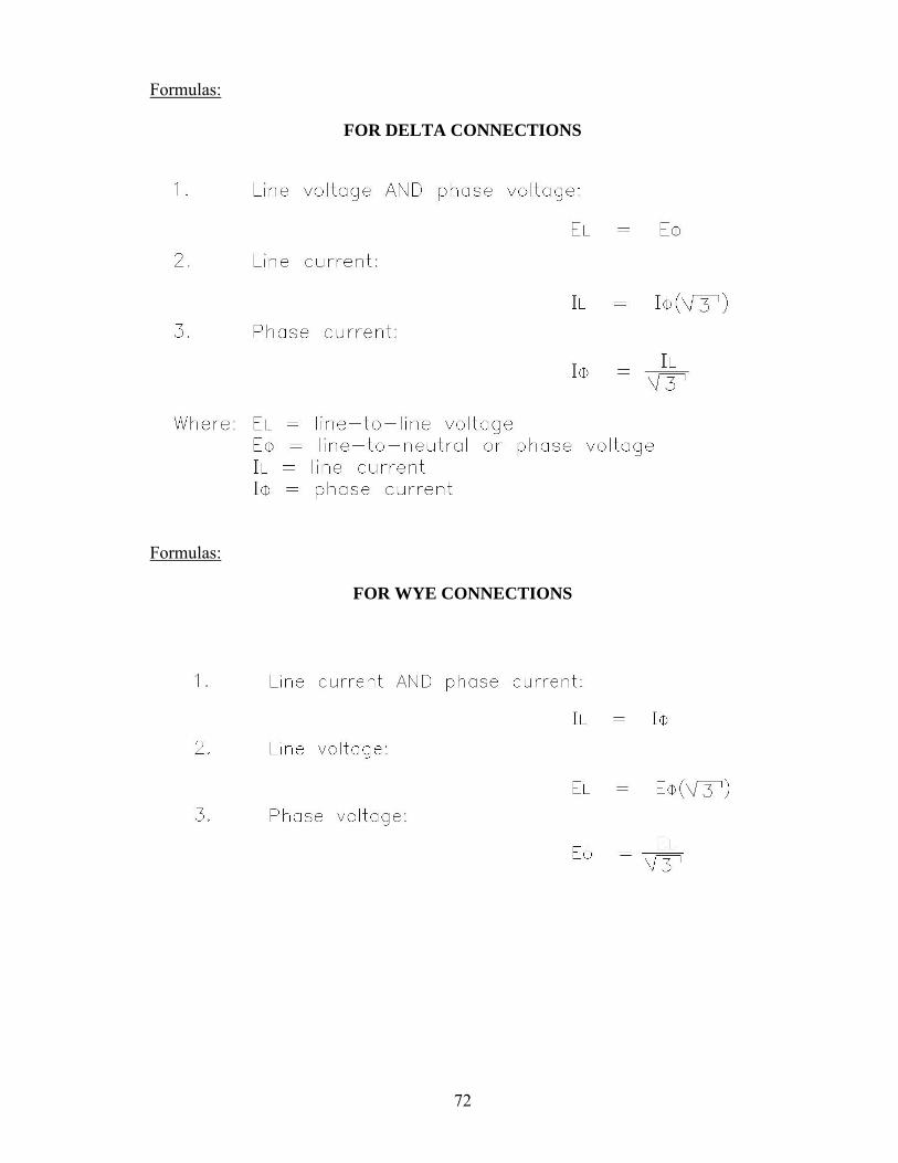
Formulas:
FOR DELTA CONNECTIONS
Formulas:
FOR WYE CONNECTIONS

73
Formulas:
FOR DELTA OR WYE CONNECTIONS
Formula: ALTERNATING MACHINE SPEED
Switches: Any switch or contacts designed to start or maintain the circuit must be wired in parallel with the original start switch. Any switch or contacts designed to stop the circuit must be wired in series with the part of the circuit they will de-energize.

74
ELECTRICAL CIRCUIT AND EQUIPMENT CONCISE DATA AND INFORMATION OUTLINE
I. Three-Phase AC
A. Essentially all large scale AC generators and distribution systems are three-phase circuits.
B. In the work place the majority of electric motors are three-phase. C. Nearly all underground and surface mining installations and machines use three-
phase AC. D. All previously mentioned AC laws and rules apply to three-phase circuits. E. The combination of three separate sine waves gives rise to three-phase circuits. F. Why use three-phase AC?
1. Three-phase is more efficient in the use of conductors. 2. More economical to transmit power. 3. More powerful and reliable motors. 4. Produces a smoother DC when rectified.
G. How is three-phase produced? 1. Three sets of poles at 120 deg. spacing. 2. Generator output is three identical sine waves separated by 120o. 3. There is always as much current going out to the load as there is coming back. 4. Total current is shared by three conductors instead of just two for a single-phase
circuit.
II. Delta Connections
A. Windings are connected end to end, and the three line leads connect to those common points.
B. Voltage and current produced by any phase winding of an alternator or transformer are called phase voltage (EΦ) and phase current (IΦ), and would be measured across or through any single winding.
C. Line voltage (EL) and line currents (IL) would be measured across or within the output lines.
D. Formulas:

75
III. Wye Connections
A. Sometimes called a star connection, but usually wye since it resembles the letter Y when drawn.
B. A wye configuration connects one end of each winding to a common point called the neutral. The other end of each winding is connected to the external line leads.
C. Formulas:
IV. Three-Phase Power Formulas
A. Formulas for power in three-phase systems must take into account the three separate windings and the 120o phase shift.
B. Apparent Power (PA) is the power supplied by the three-phase source. C. True Power (P) is the power consumed by the load resistance. D. Phase Power (PΦ) is the apparent power in any single phase winding. E. These three formulas are the same for delta and wye connections. F. Formulas:
V. Three-Phase Transformers
A. Three-phase transformers in simplest form are nothing more than a bank of three single-phase transformers.
B. Voltage can be either stepped up or stepped down. C. The same rules discussed about transformer input voltage and current vs. output
voltage and current and still apply. D. Where three-phase transformers differ from single-phase is when line voltages and
currents are considered, since these depend on whether the windings are connected by delta or wye.

76
E. Four possible connections exist for three-phase transformers 1. Delta-delta 2. Wye-wye 3. Delta-wye 4. Wye-delta
F. Calculate only Phase Voltage and Phase Current when using the ratio! G. Use the appropriate delta or wye formulas to find three-phase values after phase
voltage and phase current are known for both primary and secondary. H. Delta Secondary characteristics
1. Winding conductor size smaller than wye secondary 2. Can operate at 58% of original capacity in open delta connection. 3. Eliminates the possibility of phase unbalance due to single phase loads. 4. Disadvantage is that there is no neutral point to ground. A zigzag
transformer is usually used to derive a neutral. I. Wye secondary characteristics
1. Direct neutral that facilitates grounding 2. Higher line voltage is available than phase voltage 3. Disadvantage is that phase windings must carry full line current. 4. No option such as “open delta” exists. An open phase results in loss of
three-phase power. J. Individual applications determine whether the transformer secondary will be wye or
delta.
VI. Three-Phase Motors
A. Wherever numerous large electrical motors are used, the three-phase motor plays a major role. These motors are work horses.
B. Where single-phase motors might be a maximum of 10 HP, three-phase motors in excess of 200 HP are common.
C. Advantages of three-phase motors are: 1. They are self starting. 2. They draw lower amperages than comparable single-phase motors. 3. They are smoother running than single-phase motors and have excellent
torque. 4. They are easily reversed. Just switch any two incoming line leads to change
motor rotation. D. The most common three-phase motor is the induction motor. E. Synchronous Speed (SS):
SS = 60 f________ Pairs of poles per phase
F. Induction motor types 1. Wound Rotor 2. Squirrel Cage
G. Synchronous motors 1. Constant load and low starting torque applications. 2. Used where constant speed is critical. 3. Can be capacitive generators. 4. Not suited to rapidly changing loads.

77
VII. Circuit Protection
A. All electrical equipment shall be protected against circuits and overloads. Protective devices must be in compliance with the National Electric Code.
B. Short Circuit 1. Direct fault between two or more line leads; bypassing the normal load. 2. The protection must act instantaneously to provide circuit protection. 3. Protective devices must be set to allow motors to start. 4. Maximum allowable instantaneous trip settings for trailing cables are
specified by CFR. C. Overload (Running Overcurrent)
1. 125% of motor full load current allowed by NEC. 2. Overload devices must be slow enough to activate to allow motors to start,
but sensitive to mild overcurrent surges of long duration. 3. The simplest form of circuit protection is the fuse.
D. A dual element fuse can be used to provide short circuit and overload protection. A dual element fuse has two elements-one to protect against short circuits, and the other is to protect against overloads.
E. A circuit breaker is a switching device which automatically opens the circuit in the event of short circuit or overload; but is not destroyed in doing so.
1. A circuit breaker can be reset after tripping, and is immediately ready to continue operation.
2. A circuit breaker can also be operated manually if desired. 3. Critical factors to be considered in the selection of a circuit breaker are:
a) Voltage b) Amperage that must be interrupted c) Type of protection being provided d) Environment
4. MSHA requirement for protection of underground three-phase AC mining circuits
a) Undervoltage b) Grounded phase c) Short circuit d) Overcurrent e) Ground monitor
5. Circuit breaker instantaneous trip units provide short-circuit protection. 6. Circuit breaker thermal trip units provide overcurrent protection. 7. Under voltage and grounded phase protections are normally provided by
means of an auxiliary device called an Under Voltage Release (UVR). a) Under voltage protection provided directly by UVR. b) Grounded Phase protection requires external circuitry, but it trips the
circuit breaker via the UVR. A current transformer (CT) and ground fault relay (GFR) are used to sense the fault and open the circuit breaker UVR circuit to cause the circuit breaker to trip.
c) Perhaps the most commonly used system for ground fault protection is the balanced flux relay system.
d) Types of ground fault protection systems. i. Balanced flux relay systems ii. Direct relay systems

78
iii. Residual trip delay iv. Potential relay
8. Ground Monitor a) Continuously monitors the grounding circuit to assure continuity. b) 40 V. max on low and medium voltage systems. c) 96 V. max on high voltage systems.
VIII. Control Devices
A. Simplest form of control device is the switch. 1. SPST 2. DPST 3. SPDT (Three-way) 4. DPDT
B. Pushbutton Switches 1. Momentary 2. Maintained
C. Rotary Switches D. Automatic Switches
1. Thermostats 2. Pressure 3. Limit
E. Electromagnetic relays F. Contactors G. Line Starters H. Solenoid I. Timing Relays J. Motor-driven timer
IX. Solid State Theory
A. Semiconductors are those elements with four valence electrons. B. Rectifier
1. A rectifier changes alternating current to direct current. 2. The heart of the rectifier is a diode. A diode allows current to flow freely in
one direction, but block flow in the other. C. Diode
1. Blocks current flow in one direction. 2. Diodes are made of either silicon (Si) or germanium (Ge), but because of its
tolerance for high temperatures, the silicon diode is much more common. 3. Pure silicon is a poor conductor. Conductive properties are improved
through doping. a. N-type material b. P-type material
4. When N-type and P-type materials are joined together, they form a diode. The point of juncture is called the PN junction.
5. Forward bias 6. Reverse bias 7. Avalanche or “Zener” effect

79
8. Zener diodes act as voltage regulators 9. Reverse breakdown voltage is usually referred to as Peak Inverse Rating
(PIV). Diodes have a PIV and forward current rating. D. Half-wave rectifier E. Full-wave rectifier
1. Ripple 2. Filter capacitor
F. Three-phase, full wave bridge rectifiers provide the smoothest DC available. G. Transistors (3 layers of semiconductors)
1. PNP 2. NPN
H. Thyristor (4 layers of semiconductors) PNPN 1. SCR
X. Electrical Diagrams
A. Two separate circuits 1. Power circuit 2. Control circuit
B. Power Circuit 1. Heavy gauge wires 2. Carries higher currents 3. Usually higher voltage in three-phase AC machines.
C. Control Circuit 1. Small gauge wires 2. Carries lower current 3. Control voltage is usually lower than the power circuit and originates from a
control transformer. D. Most common types of electrical diagrams.
1. Elementary or schematic diagrams 2. Wiring diagram
E. Elementary Diagram (schematic diagram) 1. Sometimes called a line diagram 2. Circuit is reduced to its simplest, most understandable form. 3. Designed to help the electrician see how the circuit operates. 4. Makes no attempt to show exact wiring, routing, or individual connections. 5. Devices are not shown in correct physical location; in fact, they are
“exploded”, with parts scattered throughout the diagram. 6. When reading an elementary diagram, one must locate all components
having identical names. All such components are a physical part of one device.
7. Some contactors or relays have a coil and several sets of contacts. All will be given the same identifying name, regardless of where they appear on the print.
8. Names can be a single letter or combination of letters and numbers. In many cases letters or set of initials are chosen that give a clue to the device’s purpose in the circuit.

80
F. Wiring Diagram 1. The wiring diagram shows all devices in the circuit, their approximate
physical location, and their exact wiring. 2. Every coil, contact, motor, switch, fuse, etc, is included, and the lines on the
print represent actual wires. 3. A device which has several components usually is enclosed in dashed lines
to isolate it from other similar devices. 4. The wiring diagram is valuable for locating wires and circuit components
for repair and maintenance. G. Control Schemes
1. Two-wire 2. Three-wire
H. Switch Connection 1. Any switch or contacts designed to start or maintain the circuit must be
wired in parallel with the original start switch. 2. Any switch or contacts designed to stop the circuit must be wired in series
with the part of the circuit they will de-energize. I. Motor Reversing and Electrical Interlocks
XI MSHA Voltage Classifications
A. Low voltage – 0 to 660 volts B. Medium voltage – 661 to 1,000 volts C. High voltage – 1,001 volts and up

81
SAMPLE QUESTIONS FOR ELECTRIC CIRCUITS AND EQUIPMENT
TEST #3 - ELECTRIC CIRCUITS AND EQUIPMENT
1. With two equal resistances in series across a 90 volt battery, the voltage across each resistance equals:
a. 30 Volts b. 45 Volts c. 90 Volts d. 180 Volts
2. A parallel d-c circuit consists of a 10 volt battery shunted by three resistors of 3, 5, and 7
ohms. The total current equals: a. 0.667 amps b. 1.460 amps c. 15.000 amps d. 6.76 amps
3. An unknown resistor connected across a 100-volt source dissipates 200 watts. Its
resistance is: a. 50 ohms b. 100 ohms c. 200 ohms d. 500 ohms
4. A 100-ohm R is in series with 100 ohms of XL. The total impedance equals:
a. 70.7 ohms b. 100 ohms c. 141 ohms d. 200 ohms
5. A 100-ohm R is in parallel with 100-ohm of XL. The total impedance is:
a. 70.7 ohms b. 100 ohms c. 141 ohms d. 200 ohms
6. The total power present in an a-c circuit is referred to as:
a. True Power b. Apparent Power c. VARS d. Power Factor

82
7. The relationship between produced power and used power is termed? a. True power b. Apparent power c. VARS d. Efficiency
8. The power factor of an a-c circuit is equal to the ratio of:
a. True power to VARS b. Apparent power to VARS c. True power to apparent power d. Apparent power to true power
9. In a three-phase delta to delta connected transformer with a 3 to 1 step down ratio,
primary line current is: a. Equal secondary line current b. One-third secondary line current c. Three times secondary line current d. 1.73 times secondary line current
10. Of the four possible combinations possible with three-phase transformers, which will
give the greatest current handling capacity? a. Delta to delta b. Wye to wye c. Delta to wye d. Wye to delta
11. In a three-phase delta connected secondary, if one phase should open, what type power is
available for use? a. Single-phase at 100% capacity b. Single phase at 58% capacity c. Two-phase at 100% capacity d. Three-phase at 58% capacity
12. In a three-phase wye connected secondary, if one phase should open, what type power is
available for use? a. Single-phase at 33% capacity b. Single-phase at 58% capacity c. Two-phase at 100% capacity d. Three-phase at 58% capacity
13. The type AC motor which is most commonly used is the:
a. Squirrel cage b. Wound rotor c. Shaded pole d. Synchronous

83
14. If two of the phase wires which supply a 3-phase motor are reversed, the motor will: a. Stop b. Burn up c. Run as before d. Reverse its rotation
15. In a three-phase wye connected motor, the phase voltage is equal to:
a. One-third line voltage b. One-half line voltage c. 1.73 time line voltage d. .578 times line voltage
16. In the construction of a PN junction rectifier, silicon, rather than germanium, was chosen
for use in the mines because: a. It is less affected by high temperature b. It is more affected by high temperature c. Temperature has no affect upon silicon d. Germanium isn’t used in junction rectifiers
17. In a silicon diode, when a reverse voltage is applied:
a. No current flows b. A few miliamperes flow c. A few microamperes flow d. The diode will break down
18. The diode ratings usually given by manufacturers are:
a. Forward and reverse voltage b. Forward and reverse current c. Forward current and forward voltage d. Forward current and reverse voltage
19. A calibrated conductor which is designed to burn up at a specified current is called a:
a. Fuse b. Breaker c. Switch d. Relay
20. A switch which is designed to control only one circuit would probably be designated as
which of the following: a. DPDT b. DPST c. SPST d. SPDT

84
21. Draw a properly grounded single-phase transformer with a current tap.
22. In the circuit shown below find the voltage of the secondary.
23. Three single-phase transformers with a ratio of 15:1 are connected delta-wye.
If 4160 volts is supplied to the primary side of the transformers, what is the line-to-line voltage on the secondary side?
24. Draw a three-phase delta secondary with zigzag ground transformers.

85
25. What is the source voltage below?
26. What is the current flow in the circuit below?
27. Calculate the total current flow in the circuit below.
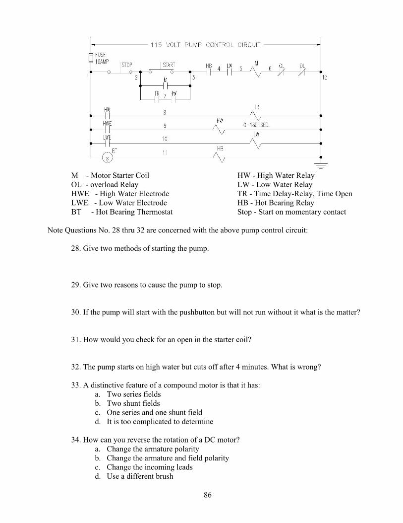
86
M - Motor Starter Coil HW - High Water Relay OL - overload Relay LW - Low Water Relay HWE - High Water Electrode TR - Time Delay-Relay, Time Open LWE - Low Water Electrode HB - Hot Bearing Relay BT - Hot Bearing Thermostat Stop - Start on momentary contact Note Questions No. 28 thru 32 are concerned with the above pump control circuit:
28. Give two methods of starting the pump.
29. Give two reasons to cause the pump to stop.
30. If the pump will start with the pushbutton but will not run without it what is the matter?
31. How would you check for an open in the starter coil?
32. The pump starts on high water but cuts off after 4 minutes. What is wrong?
33. A distinctive feature of a compound motor is that it has:
a. Two series fields b. Two shunt fields c. One series and one shunt field d. It is too complicated to determine
34. How can you reverse the rotation of a DC motor?
a. Change the armature polarity b. Change the armature and field polarity c. Change the incoming leads d. Use a different brush

87
35. During the charging of lead-acid cell, a dangerous, highly explosive gas is emitted from
the cell. It is: a. Nitrogen b. Methane c. Oxygen d. Hydrogen
36. The source V of a DC motor is 290V. When the motor is running, the voltage at the
motor is 260V and draws 170 amp’s. What is the resistance of the cable? a. 1.71 Ω b. 1.12 Ω c. 1.53 Ω d. 0.18 Ω
37. Which of the following is required by all AC motors in order to operate properly?
a. A rotating magnetic field b. A phase shift capacitor c. Two or more phases d. A split phase
38. What is the full load secondary current of a single phase .2kVA transformer at 120V?
a. 16 A b. 1.6 A c. 3 A d. 24 A
39. Which 460V, 3-Phase AC motor requires the largest leads?
a. 220V 40 HP b. 220V 80 HP c. 550V 40 HP d. 550V 80 HP
40. Inductive reactance decreases with:
a. An increase in frequency b. An increase in inductance c. Both A and B d. Neither A or B
41. Capacitive reactance decreases with:
a. An increase in frequency b. An increase in capacitance c. Both A and B d. Neither A or B

88
42. Name four (4) things that are required to be recorded on the map of a mine electrical system.
a. (1)____________________________________________________________
b. (2)____________________________________________________________
c. (3)____________________________________________________________
d. (4)____________________________________________________________
43. Capacitors are used for:
a. Arc reduction b. Correcting power factors c. Filtering electrical current d. All of the above
44. VARS is the measure of:
a. Resistive power b. Reactive power c. Apparent power d. True power
45. A transformer has a primary voltage of 100V with 500 turns and a secondary voltage of
200V with 1,000 turns. What is the turns ratio? a. 1:5 b. 5:1 c. 1:2 d. 2:1
46. In a three-phase wye-connected transformer primary, the phase voltage is equal to:
a. One-third the line voltage b. One-half the line voltage c. 1.73 times line voltage d. 0.578 line voltage

89
Figure 1
47. What is the peak-to-peak voltage when the effective voltage is 100 volts (Fig. 1)?
a. 141.4 volts b. 282.8 volts c. 110.0 volts d. 200 volts
48. What is the full load primary current of a 3 phase, 4,160 to 480 volt transformer with a
500kVA rating? a. 84 b. 169 c. 96 d. 69
49. If this transformer had a 4% impedance, what would the primary short circuit current be?
a. 690 b. 384 c. 1,932 d. 1,725
Figure 2
50. What is the secondary line voltage (Fig. 2)?
a. 480V b. 277V c. 550V d. 600V

90
51. If the secondary line current is 200 amps, what is the primary line current?
a. 7.7 b. 3,000 c. 13.3 d. 11
Figure 3
52. Give one method of starting the pump (Fig. 3). a. Push the start button b. The low water relay starts the pump automatically c. Close the ON contactor d. Open the LW coil
53. Two things that will stop the pump (Fig. 3) are:
a. ol & HW b. HB & TR c. LW & ol d. TR & HW
54. Of the four possible combinations with three-phase transformers, which will give the
greatest current handling capacity? a. Wye to delta b. Delta to wye c. Wye to wye d. Delta to delta

91
55. Draw a Delta transformer schematic supplying a 3-phase bridge rectifier. 56. Three single-phase transformers with a ratio of 15:1 are connected delta-wye. If 4,160V
is supplied to the primary side of the transformers what is the line- to-line voltage on the secondary side?
a. 160V b. 480V c. 2,405V d. 7,197V
57. A circuit breaker directly protects:
a. Wire b. Men c. Equipment d. Switches

92
ANSWER SHEET FOR ELECTRIC CIRCUITS AND EQUIPMENT
1. b 2. d 3. a 4. c 5. a 6. b 7. d 8. c 9. b 10. d 11. d 12. a 13. a 14. d 15. d 16. a 17. c 18. d 19. a 20. c
21.
22. 4600 = 230 Volts 20 E = (4160) (1.732) 15
23. E = 480 Volts
24.

93
25. E = 40 = 5 Volts 8
26. I = 90 = 3 amperes 30
27. I1 = 240 = 24 amps 10 I2 = 240 = 12 amps 20 IT = I1 + I2 = 24 + 12 = 36 amperes
28. Start Pushbutton High Water Relay
29. Stop Pushbutton Overload
Hot Bearing Relay Blown Fuse Low Water Relay
30. Faulty “M” holding contacts 31. Remove power, lock out and tag out
Check for continuity between 5 and 6 with an ohmmeter 32. Hot Bearing
Overload Blown Fuse
33. c 34. a 35. d 36. d 37. a 38. b 39. b 40. d 41. c 42. (1)Permanent Cables
(2)Switchgear (3)Transformers (4)Permanent Pumps
43. d 44. b 45. c 46. d 47. b 48. d 49. d 50. b

94
51. a 52. a 53. c 54. a
55.
56. b 57. a

95
TEST #4
PERMISSIBILITY OF ELECTRICAL EQUIPMENT

96
UTAH MINE ELECTRICIAN CERTIFICATION EXAMINATION STUDY GUIDE
IV. TEST #4 - Permissibility Of Electrical Equipment Outline
A. Most questions are related to CFR, Part 18 B. Trailing cable rating in accordance to IPCEA C. Hand tool safety device requirements D. Frame-to-ground potential limitations as per CFR, Part 18 E. Fire protection requirements for unattended, enclosed, equipment F. Criteria for plugs for spare lead entrances, including radial clearance G. Surface temperature limitations of machine components H. Fastening requirements for explosion proof enclosures such as a bolt length, bolt
size, studs, washers, packing nuts, stuffing boxes, and thread engagement
I. Electrical and mechanical protection requirements for cables entering splice boxes and between machine components
J. Slip switch requirements for conveyor belts and exemptions K. Trailing cable installation requirements L. Cable reel requirements M. Machine headlight requirements N. Allowable method of making splices in power cables between machine components O. Maximum allowable clearances
1. Step flange 2. Plane flange 3. Motor end-bells 4. Cylindrical switches and joints
P. Purpose of hose conduit Q. Permissible machine criteria and maintenance
1. Approval by MSHA 2. Maintained in permissible condition 3. Fire and explosions can result from inadequate maintenance
R. Definitions 1. Explosion-proof 2. Intrinsically-safe
S. Requirements for cable and wires that pass through metal walls of electrical compartments
T. Requirements for temporary cable splices 1. Low and medium voltage 2. High voltage

97
PERMISSIBILITY There are three main types of joints that are used most commonly on permissible enclosures. These joints are classified as plane flange joints, step flange joints, and threaded joints. Plane Flange Joints – Refer to Figure 5 A plane flange joint is one which has to adjoining surfaces in parallel planes or a smooth metal to metal joint. A good example of the plane flange joint can be observed on most shuttle car panel covers. In order for a plane flange joint to be permissible, it must not have a clearance or tolerance greater than 0.004 inches after it is securely bolted in place. An inspector will check this clearance with a 0.005 inch feeler gauge. Plane flange joints cannot be made permissible by the use of gaskets, permatex, or epoxy. The minimum distance for the flame resistant path is 1 inch. The cover must be securely fastened with bolts and lock washers. The bolts must be located at intervals not exceeding 6 inches. If bolts of ½ inch diameter are use then the threaded bolt stub must be at least ½ high in length, thus a 5/8 inch bolt would have to have a threaded stub of least 5/8 inches in length. There must be at least 1/8 inch at the bottom of the bolt hole after the bolt is securely fastened. The purpose of this is in case a lock washer was left off, the bolt would still tighten. The minimum distance between the threaded portion of the bolt holes and the inside of the box cannot be less than 7/16 inch. When the threads of bolt holes in a permissible enclosure become stripped there are 3 ways they can be repaired, which are as follows:
1. Use a heli-coil 2. Fill the whole by welding, then re-drill and tap to the original size. Drill to a larger size and re-tap for larger bolt. Caution must be taken to maintain the minimum 7/16 inch clearance from the edge of the bolt hole and the inside of the enclosure.

98
TYPICAL PLANE JOINT 1/2” – 13 Cap screw Lock washer From hole to inner edge 7/16” Cover Maximum clearance 0.004” Minimum Engagement ½” Minimum stock 1/8” Inside of enclosure 1”
Figure 5
3. Step Flange Joint – Refer To Figure 6 A step flange joint means a joint comprised of two adjoining surfaces with a change in direction between its inner and outer edges. (A step flange joint may be composed of a cylindrical portion and a plane portion or two or more plane portions). The maximum permissible clearance of the step flange joint is 0.006 inch. An inspector will check this clearance with a 0.007 inch feeler gauge. The cylindrical fit of a step flange joint must extend into its hole a minimum of 1/8 inch. The maximum allowable clearance between the step and the box is 0.003 inches when the step is greater than 1/8 inch less but than 1/4 inch. If the length of the step is greater than or equal to ¼ inches, then the maximum allowable clearance between the step and the box is 0.004 inches. If a ½ inch bolt is used the threads have to extend into the bolt hole a minimum of ½ inch. Likewise a 5/8 inch bolt has to have a minimum of 5/8 inches of threads. The flame path of the step flange joint must be at least ¾ inches. Some examples of a step flange joint are the endbells on most motors, safe-off-reset switches on shuttle cars, and inspection boxes on motors.

99
TYPICAL STEP FLANGE JOINT 1” 2 - 13 Cap screw Lock washer Cover Shall be greater than 1”/8 a + b shall not be less Maximum clearance than 3”/4 c = 0.006” 1” < b < 1”, d = 0.003” Minimum engagement, 1” 8 4 2 b < 1” d = 0.004” 4 Inside of enclosure
FIGURE 6 Threaded Joint – Refer to Figure 7 A threaded joint means a joint consisting of a male and a female-threaded member, both of which are of the same type and gauge. The flame path of a threaded joint is around the threads and must be a minimum of 1 inch. Threaded covers shall be designed with Class 1 (coarse, loose fitting) threads. The cover shall be tightened, locked, and wired. Another type joint is called a cylindrical joint, which means a joint comprised of two contiguous, concentric, cylindrical surfaces. Examples of cylindrical joints are the off-on switches and safe-off-reset switches found on the machinery. The maximum allowable clearance for this type of joint is 0.010 inches for a 1 inch flame path. An inspector will use a 0.011 inch feeler gauge for checking. If the flame path is ¾ inch then the maximum clearance is 0.008 inches. An inspector will now use a 0.009 inch feeler gauge for checking. Headlight enclosures are part of the permissible equipment on a machine, and they must be checked weekly. The headlight must burn. Proper entrance glands must be installed and locked. Fire resistant conduit must protect the headlight cables and this conduit must be clamped to the entrance gland. The headlight must be securely fastened to the machine with all bolts in place. The headlight lens must be securely locked in place and should not be cracked or broken. The headlight unit must be properly assembled. All permissible enclosures must be bolted tightly to the frame of the machine. All wires or cables must enter an enclosure through a cable entrance gland. The compressed packing in this gland must be untreated rope asbestos or an approved alternate.

100
If a standard packing gland if properly packed, there will be a minimum clearance of 1/8 inch between the shoulder of the nut and the top of the stuffing box. The compressed packing in this gland must extend along the cable for a minimum of ½ inch. If the cable entrance glands or packing glands were approved by the Bureau of Mines with lock nuts, then the nuts must be locked and securely wired. If a 1-inch diameter cable was removed from a packing gland and replaced with a ¾ inch diameter cable this would be a violation because the clearance between the outer diameter of the cable and the inner diameter of the cable and the inner diameter of the stuffing box is too large. The clearance between the stuffing box and the cable cannot exceed 75% of the diameter of the packing material. Assuming that ¼ inch packing material is used, the maximum allowable clearance would be 3/16 inches. The clearance left by replacing 1-inch cable with ¾ inch cable is ¼ inch clearance, and constitutes a permissibility violation. Hose conduit shall be provided for mechanical protection of all machine cables that are exposed to damage. Hose conduit shall be flame resistant and have a minimum wall thickness of 3/16 inch. All conduit hose must have flame resistant and the Bureau of Mines identification written on it. Any piece of underground mobile equipment that travels in excess of 2-1/2 (two and one-half) miles per hour must have a cable reel. The maximum speed of any underground equipment is 6 miles per hour. All trailing cables must be entirely insulated. All spooling devices must be oiled and kept in good condition to prevent damage to the cable. All cables must have size, type, company, and Bureau of Mines number and approval written on it. THREADED JOINT Cover Total developed length to conform to 18.31 (a)(6) - Class 1 fit
Figure 7

101
Volume of empty closure Less than
45 cu.in 45 to 124 cu. in. inclusive
more than 124 cu. in.
Minimum thickness of material for walls 1/8” 3/16” ¼” Minimum thickness of material for flanges ¼” 1 3/8” 2 ½” 2 Minimum thickness of material for cover ¼” 1 3/8” 2 ½” 2 Minimum width of joint-all in one plane ½” ¾” 1” Maximum clearance-joint all in one plane 0.002” 0.003” 0.004” Minimum width of joint, portions of which are in different planes cylinder or equivalent:
3/8” 3 5/8” 3 ¾” 3
Maximum clearances-joint in two or more planes, cylinders or equivalent:
a) portion perpendicular to plane 0.008” 4 0.008” 4 0.008” 4 b) plane portion 0.006” 0.006” 0.006” Maximum bolt (5) spacing-joints all in one plane 6” with
minimum of 4 bolts
6” with minimum of 4 bolts
6”
Maximum bolt spacing-joints, portions of which Are in different planes
(6) (6) (6)
Minimum diameter of bolt (without regard to type Of joint)
¼” ¼” 3/8”
Minimum thread engagement (7) ¼” ¼” 3/8” Maximum diametrical clearance between bolt body and unthreaded holes through which it passes (8)
1/64” 1/32” 1/16”
Minimum distance from interior of enclosure to the edge of the bolt hole: Joint-minimum width 1”
7/19” 9
Joint-less than 1” wide 1/8” 3/16”
Cylindrical Joints Shafts centered by ball or roller bearings: Minimum length of flame-arresting path
½” ¾” 1”
Maximum radial clearance 0.010” 0.0125” 0.015” Shafts through journal bearings: 10 Minimum length of flame-arresting path ½” ¾” 1” Maximum radial clearance 0.003” 0.004” 0.005” Other than shafts: Minimum length of flame-arresting path ½” ¾” 1” Maximum radial clearance 0.0015” 0.002” 0.003”

102
1 1/32-inch less is allowable for machining rolled plate. 2 1/16-inch less allowable for machining rolled plate. 3 If only two planes are involved, neither portion of a joint shall be less than 1/8-inch wide, unless the wider portion conforms to the same requirements as those for a joint that is all in one plane. If more than two planes are involved (as in labyrinths or tongue-and-groove joints) the combined lengths of those portions having prescribed clearances will be considered. 4 The allowable diametrical clearance is 0.008 inch when the portion perpendicular to the plane portion is 1/4 inch of or greater in length. If the perpendicular portion is more that 1/8 inch but less than ¼ inch wide, the diametrical clearance shall not exceed 0.006 inch. 5 Where the term ‘bolt” is used, it refers to a machine bolt or a cap screw, and for either of these studs may be substituted provided the studs bottom in blind holes, are completely welded in place, or the bottom of the hole is closed with a secure plug. Bolts shall be provided at all corners. 6 Adequacy of bolt spacing will be judged on basis of size and configuration of the enclosure, strength of materials, and explosion test results. 7 In general minimum thread engagement shall be equal to or greater than the diameter of the bolt specified. 8 Threaded holes for fastening bolts shall be machined to remove burrs or projections that affect planarity of a surface forming a flame-arresting path. 9 Less than 7/16-inch (1/4-inch minimum) will be acceptable provided the diametrical clearance for fastening bolts does not exceed 1/32 inch. 10 Shafts or operating rods through journal bearings shall be not less than ¼-inch in diameter. The length of fit shall not be reduced when a push button is depressed. Operating rods shall have a shoulder or head on the portion inside the enclosure. Essential parts riveted or bolted to the inside portion will be acceptable in lieu of a head or shoulder, but cotter pins and similar devices will not be acceptable.

103
SAMPLE QUESTIONS FOR PERMISSIBILITY OF ELECTRICAL EQUIPMENT
TEST #4 – Permissibility of Electrical Equipment
1. The flame path under control panel covers on shuttle cars is a: a. Step flange joint b. Plane flange joint c. Tongue and groove joint d. Combination step flange and plane joint
2. The maximum allowable opening in flame paths of panel covers on shuttle cars is:
a. .004 inch b. .006 inch c. .010 inch d. .005 inch
3. The minimum allowable length of flame path for such joints is:
a. 1 ¼ inch b. 2 inches c. 1 inch d. ¾ inch
4. Changes in electrical components of permissible equipment must be:
a. Recorded only in the electrical equipment inspection book at the mine b. Approved by State and Bureau of Mines and reported to the mine inspector during the
next inspection c. Made in a workman like manner and reported to the mine inspector during the next
inspection d. Made only by qualified persons
5. The maximum allowable surface temperature of all components on machines approved under
schedule 2G is: a. 150 degrees centigrade b. 300 degrees centigrade c. 100 degrees centigrade d. 250 degrees centigrade
6. The primary purpose of a breather on explosion-proof compartment is:
a. To keep the parts cool b. To allow harmful gases that cause corrosion to escape c. To provide inspection openings d. To let methane out of the compartment

104
7. Unused entrance glands must be: a. Closed with neoprene fire resistance plugs b. Left open c. Closed with secured metal plugs d. Plugged with short lengths of cable
8. What are some of the dangers created by the operation of electrical equipment in coal mines?
a. Hernia in workman from pulling cables b. Stray currents blowing fuses c. Fires from overheated equipment and explosions from arcs d. Open overload relays due to excessive current draw of electric equipment
9. How is permissibility of equipment commonly destroyed?
a. By proper maintenance b. By improper mining cycle c. By improper maintenance d. None of the above
10. What should not be permitted to accumulate in the boxes enclosing contactors and switches.
a. Extra parts b. Stray currents c. Coal dust d. Methane-air mixtures
11. Where permissible power connection units are not available, how shall all power connections
points out by the last open crosscut be made? a. In intake air b. In output air c. With rigid connectors d. Best method not to interfere with production
12. What is the maximum number of temporary splices permissible in trailing cables?
a. One b. Two c. Three d. Four
13. How long may a trailing cable be used which has been temporarily spliced?
a. 12 hours b. 24 hours c. 36 hours d. 48 hours

105
14. Cable reels must be installed on all equipment that receives electric power through cables and travel:
a. Not over two miles per hour b. More than 2 ½ miles per hour c. Distances that exceed 1,000 feet d. Grades exceeding 2 ½ percent
15. The dielectric strength of power wires and cables is required to be at least equal to the voltage
of the circuit, on and after what date? a. March 30, 1970 b. March 30, 1971 c. March 30, 1972 d. March 30, 1974
16. High voltage circuits extending to mobile or portable equipment such as shovels and portable
transformer shall be: a. Provided with a resistance grounded neutral and protected by dual element fuses b. Provided with a resistance grounded neutral and protected by a circuit breaker c. Protected by dual element fuses d. Supplied power from a solidly grounded, wye connected bank
17. The approved method of grounding for metallic sheaths, armors, and conduits in resistance
grounded systems where the enclosed conductors are a part of the system is to use: a. A solid connection to the neutral conductor b. A #8 wire firmly connected to the earth ground rod c. A #4 wire with permissible coupling to the trolley track d. Any of the above fulfill the requirements of the law
18. There are four approved methods for grounding of metallic frames, casing, and other enclosures
of electric equipment receiving power from D.C. power systems with one polarity grounded. Which of the following is NOT specified as permissible?
a. A solid connection to the mine track b. A solid connection to the grounded conductor of the system c. Silicon diode grounding d. Connection to any existing grounding system
19. Which of the following is NOT a permissible method of grounding equipment receiving power
from an ungrounded delta system? a. A solid connection to a borehold casing having low resistance to earth b. A solid connection to metal waterlines having low resistance to earth c. A solid connection to a grounding conductor extending to a low resistance ground field
located on the surface d. A solid connection to the ground rod
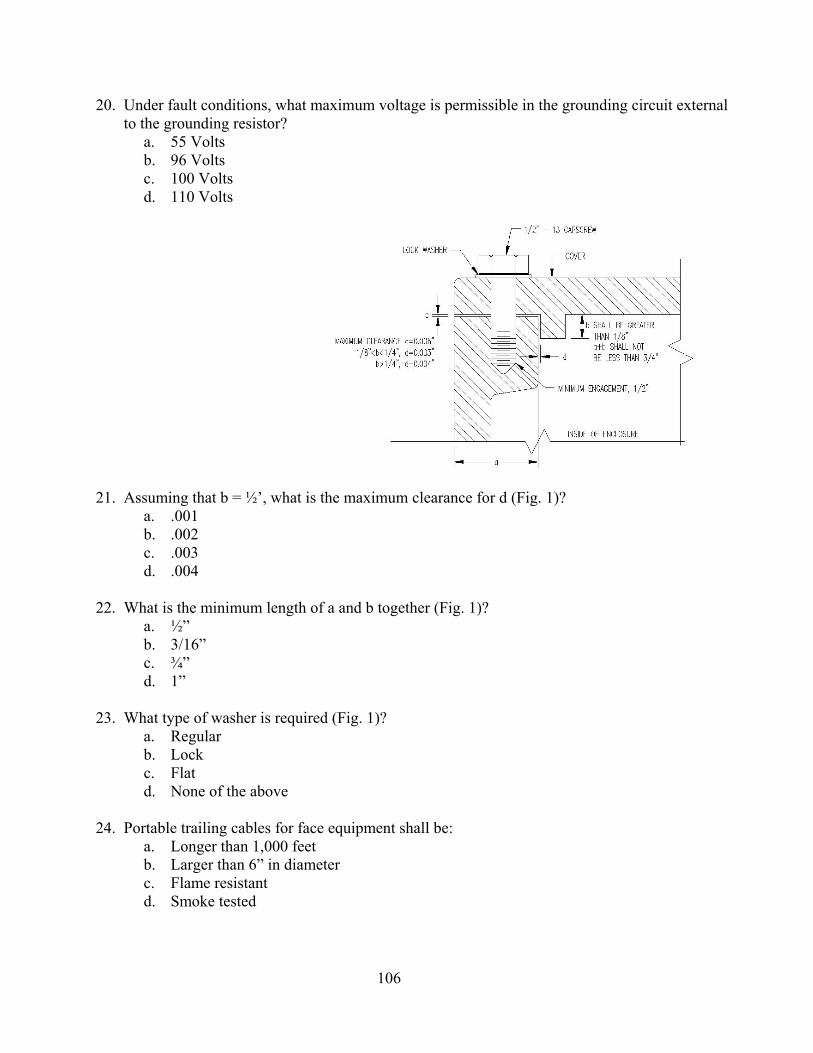
106
20. Under fault conditions, what maximum voltage is permissible in the grounding circuit external to the grounding resistor?
a. 55 Volts b. 96 Volts c. 100 Volts d. 110 Volts
21. Assuming that b = ½’, what is the maximum clearance for d (Fig. 1)? a. .001 b. .002 c. .003 d. .004
22. What is the minimum length of a and b together (Fig. 1)?
a. ½” b. 3/16” c. ¾” d. 1”
23. What type of washer is required (Fig. 1)?
a. Regular b. Lock c. Flat d. None of the above
24. Portable trailing cables for face equipment shall be:
a. Longer than 1,000 feet b. Larger than 6” in diameter c. Flame resistant d. Smoke tested

107
25. When electrical work is to be performed, the appropriate disconnecting devices shall be open, locked out and tagged by:
a. The person(s) who are to perform the electrical work b. Any miner who happens to be in the area c. The faceboss d. The Secretary or his authorized representative
26. Under most circumstances, who should remove locks or tags from the electrical circuits that
have been de-energized, locked out and tagged? a. The Mine Foreman b. The Secretary c. ONLY by the person(s) who locked out and tagged the circuit(s) d. The Maintenance Foreman
27. The maximum allowable opening in the flame paths of main panel covers on Shuttlecars is:
a. .004 inch b. .005 inch c. .006 inch d. .010 inch
28. What is the minimum length for a plane flange flame arresting path over 124 cubic inches?
a. 1 inch b. ½ inch c. ¼ inch d. Not important
29. The flame path under the main control panel covers on 10SC22 Shuttlecars is a:
a. Step flange joint b. Plane flange joint c. Tongue and groove joint d. Combination step flange and plane flange joint
30. What size gauge is used to check end bells on motors by Federal and State Inspectors?
a. .004 b. .005 c. .006 d. .007
31. What size is used by a Federal or State Inspector to check a Joy Shuttlecar Control Box?
a. .003 b. .004 c. .005 d. .006

108
32. The minimum allowable length of flame path for a step joint is: a. 1-1/4 inches b. 2 inches c. ¾ inches d. 1 inch
33. How often must fire equipment be inspected?
a. Yearly b. Every month c. Every 6 months d. Every 3 months
34. Changes in electrical components of permissible equipment must be:
a. Made only by qualified persons b. Approved by State and Bureau of Mines and reported to the Mine Inspector during the
next inspection c. Recorded only in the electrical equipment inspection book at the mine d. Made in a workman-like manner and reported to the Mine Inspector during the next
inspection
35. Unused entrance glands must be: a. Plugged with short lengths of cable b. Closed with neoprene fire resistance plugs c. Left open d. Closed with secured metal plugs
36. The maximum allowable surface temperature of all components on machines approved under
Schedule 2G is: a. 100o Centigrade b. 150o Centigrade c. 250o Centigrade d. 300o Centigrade
37. The primary purpose of a breather on explosion-proof compartments is: a. To let methane out of the compartment b. To keep the parts cool c. To allow harmful gasses that cause corrosion to escape d. To provide inspection openings
38. The minimum distance between the packing gland nut and the stuffing box of a properly
installed cable assembly is: a. 1/16 inch b. 1/8 inch c. ¼ inch d. ½ inch

109
39. In order to qualify as permissible, a step flange joint must extend into its opening at least: a. 1/16 inch b. 1/8 inch c. ¼ inch d. 1 inch
40. How long may a trailing cable be used which has been temporarily spliced?
a. 48 hours b. 36 hours c. Not over 24 hours d. 12 hours
41. Where permissible power connection units are not available, where shall all power connection
points outby the last open crosscut be made? a. Best method not to interfere with production b. In intake air c. In output air d. With rigid connectors
42. The maximum allowable voltage for hand-held electric drills is:
a. 300VAC or 300VDC b. 220VAC or 110VDC c. 480VAC or 480VDC d. 110VAC or 220VDC
43. All hand-held electrical equipment shall be provided with:
a. AC motors or DC motors b. Two Pole Switch of the Deadman-Control Type c. Three-phase power d. Ground diodes
44. The minimum allowable size of trailing cables on DC powered equipment is:
a. #8 b. #6 c. #4 d. #2
45. The minimum allowable size of trailing cables on AC powered equipment is:
a. #2 b. #4 c. #6 d. #8

110
ANSWER SHEET FOR PERMISSIBILITY OF ELECTRICAL EQUIPMENT
1. b 23. b 2. a 24. c 3. c 25. a 4. b 26. c 5. a 27. a 6. b 28. a 7. c 29. b 8. c 30. d 9. c 31. c 10. c 32. c 11. a 33. c 12. a 34. b 13. b 35. d 14. b 36. b 15. a 37. c 16. b 38. b 17. a 39. b 18. d 40. c 19. d 41. b 20. c 42. a 21. d 43. b 22. c 44. c 45. c

111
TEST #5
MINE LAW – 30 CFR, PART 77 (SURFACE)

112
UTAH MINE ELECETRICIAN CERTIFICATION EXAMINATION STUDY GUIDE
TEST #5 - Mine Law 30 CFR, Part 77 (Surface)
A. Electrical Protection Requirements
1. Trailing cables 2. Three-phase electrical motors 3. Lightning arresters 4. Underground high-voltage circuits
B. Grounding Requirements 1. High-voltage electrical equipment 2. Minimum ground conductor sizes of circuits and cables 3. Minimum size of internal and external ground check conductors
C. Trailing cable temporary splice time and distance limitations D. High-voltage circuit breaker application and testing requirements E. Lockout requirements prior to performing electrical work
1. Disconnect switches 2. Locked and tagged out
F. Ground fault current and voltage limitations 1. Low-and-medium-voltage limitations, three-phase circuits 2. High-voltage, three-phase circuits
G. Minimum distance between lightning ground (substation ground grid) and neutral ground (mine ground grid)
H. Definition of voltage classification 1. Low voltage (0-660 Volts) 2. Medium voltage (661-1000 Volts) 3. High voltage (1001Volts and Above)
I. Requirements for cables and wires entering metal frames or electrical equipment J. Ground monitor circuit criteria
1. Low-and-medium-voltage circuits 2. High-voltage circuits
K. Danger sign requirements for electrical installations on the surface (Part 77) L. Troubleshooting and testing exemptions, requirements, limitation, and comparison to performance
of electrical work M. High-voltage cable protection and guarding requirements
1. Regular work areas 2. Minimum height to prelude guarding
N. Re-qualifications requirements for qualified (certified) electricians O. Work may never be performed on energized underground high-voltage circuits L. Protective equipment requirements for:
1. Disconnecting energized surface high-voltage lines 2. Handling energized low, medium, and high-voltage trailing cables 3. Troubleshooting and testing

113
M. Grounding resistors 1. Voltage and current required ratings
2. Theory of operation and personnel safety enhancement 3. Criteria regarding current and voltage limitations
A. High-voltage circuits B. Low and Medium-voltage circuits
N. High-voltage circuits entering the underground area of any coal mine shall be protected with a circuit breaker located on the surface to provide protection against the following:
1. Undervoltage 2. Grounded phase 3. Short circuit 4. Overcurrent

114
SAMPLE QUESTIONS FOR SURFACE ELECTRICIAN
TEST #5 - Coal Mine Health and Safety Act Part 77 – (Surface)
1. High voltage power lines must be installed a minimum of: a. 30 feet above ground b. 100 feet above ground c. 15 feet above ground d. 50 feet above ground
2. Where high voltage power lines are installed over driveways, haulage ways and railroad tracks
they must be installed a minimum of: a. 30 feet above ground b. 15 feet above ground c. 50 feet above ground d. 100 feet above ground
3. When operating equipment having a boom or mast, the minimum distance allowed between the
boom or mast and a 69,000 to 114,000 volt powerline must be: a. 12 feet b. 20 feet c. 35 feet d. 6 feet
4. Ground wires used to ground metallic sheaths, armors, conduits, frames, casing and other metallic
enclosures shall be: a. Equal in cross sectional area to that of the conductor b. Equal to ½ of the cross sectional area of the power conductor if the power conductor is #6
AWG or larger c. No smaller than the #6 AWG
5. Circuit breakers for high voltage circuits of surface distribution systems for mobile equipment:
a. Must provide short circuit and overcurrent protection b. Must provide grounded phase protection c. Must provide under-voltage protection d. All of the above
6. Preparation plants, dryer plants, tipples, draw-off tunnels, shops, and other surface installations
shall be equipped with which of the following lists of fire fighting equipment: a. Two fire extinguishers and 240 lbs. Of rock dust b. Two portable fire extinguishers, and one additional fire extinguisher for each 10,000 cubic
feet volume in the structure c. One portable fire extinguisher for each room in the building d. Complete fire sprinkler system

115
7. When welding, cutting or soldering with arc or flames: a. One portable fire extinguisher must be provided at the location b. Precautions shall be taken to make sure that smoldering metal or sparks do not result in a
fire c. In areas likely to contain methane, a methane check must be made d. All of the above
8. When moving portable substations and transformers:
a. They must be de-energized before they are moved b. They may be moved while energized if special precautions are taken c. They must be completely disconnected d. They may be moved energized since the frames are grounded
9. High voltage circuit breakers and disconnect switches:
a. Must be located close to the equipment they control b. Must be labeled to show which circuits they control, unless identification can be made
readily by location c. May not be used to protect more than one circuit d. None of the above
10. Grounding resistors where required in low and medium voltage circuits shall be of an ohmic value
to limit the fault current to: a. 15 amps b. 50 amps c. 25 amps d. 100 amps
11. Power circuits and electric equipment shall be de-energized before work is done on such circuits
and equipment, except: a. When given permission by the Mine Superintendent b. When troubleshooting or testing c. When given permission by the Electrical Inspector d. There is no exception
12. Who may perform electrical work on electric distribution circuits or equipment?
a. By any Journeyman or Master Electrician b. By a Graduate of an Accredited Electrical School c. Only by a qualified person by definition of the Act or by a person trained to perform
electrical work under the direct supervision of a qualified person d. A person designated by the Mine operator

116
13. What is the proper procedure prior to performing work on electric equipment? a. The power must be removed by turning the circuit breaker off b. The Foreman must remove the power c. The power must be removed by means of an approved visible disconnect and locked or
tagged out by the person who performs such work d. The power must be removed by means of an approved visible disconnect and locked or
tagged out by any qualified electrician
14. Who may remove locks or tags from electrical equipment? a. The Mine Superintendent b. The Electrical Inspector c. Any qualified electrician d. Only by the persons who installed them, or if such persons are unavailable, by persons
authorized by the operator or his agent
15. What is the frequency of examination of surface electrical equipment? a. At least daily b. At least weekly c. At least monthly d. At least yearly
16. Which of the following is not a requirement of electric conductors on the surface?
a. Sufficient in size and have adequate current-carrying capacity for the load b. Constructed such that a rise in temperature resulting from a normal operation will not
damage the insulating materials c. Meet the minimum requirements for ampacity provided in the National Electric Code 1968 d. Possess a MSHA approval number
17. The ampacity of trailing cables for surface equipment shall meet the minimum requirements set
forth in: a. National Electric Code 1968 b. Current National Electric Code c. Schedule 2G d. Insulated Power Cable Engineers Association – National Electric Manufacturers
Association standards in effect when cables are purchased
18. Cables shall enter metal frames of surface electric equipment only through: a. Cable glands b. Proper fittings c. Junction boxes d. Pot heads

117
19. All surface electric equipment and circuits shall be provided with what type of protection: a. Short circuit and overload b. Overvoltage and overload c. Grounded phase and overload d. Undervoltage and overload
20. Electrical protective devices shall conform to what standards?
a. IPCEA – NEMA b. National Electric Code 1968 c. IEEE d. Underwriters Laboratory
21. Where shall lighting arrestors protecting exposed telephone wires entering buildings be located?
a. Within 100 feet of the point where they enter the building b. At the point where they enter the building c. At the main terminal block for the telephone system on mine property d. None of the above
22. Which of the following is not a requirement for the installation of a surface transformer?
a. Transformer shall be of the totally enclosed type, or shall be placed at least 8 feet above the ground, or installed in a transformer house, or surrounded by a substantial fence at least 6 feet high and at least 3 feet from any energized parts, casings, or wiring
b. Transformer stations shall be enclosed to prevent persons from unintentionally or inadvertently contacting energized parts
c. Transformers shall be housed in fireproof enclosures d. Transformer enclosures shall be kept locked against unauthorized entry
23. What is the maximum allowable voltage for bare signal or control wires?
a. 24 volts b. 40 volts c. 96 volts d. 100 volts
24. What requirements must be met by all electric wiring and equipment installed after June 30, 1971?
a. Comply with National Electrical Code 1968 b. Comply with National Electrical Code 1971 c. Comply with National Electrical Code in effect at the time of installation d. Comply with Schedule 2G
25. What is the proper method of grounding metallic sheaths, armors, and conduits in resistance-
grounded systems where the enclosed conductors are a part of the system? a. A solid connection to metal waterlines having low resistance to earth b. A solid to a grounding conductor, other than the neutral conductor of a resistance-grounded
system, extending to a low-resistance ground field c. A solid connection to the AC neutral ground conductor of the resistance-grounded system d. None of the above

118
26. Which of the following is not an approved method of grounding metallic sheaths, armors, and conduits in all systems other than neutral resistance-grounded systems?
a. A solid connection to metal waterlines having low resistance to earth b. A solid connection to a grounding conductor, other than the neutral conductor of a
resistance-grounded system, extending to a low-resistance ground field c. A solid connection to the AC neutral ground of a resistance-ground system d. Any other method of grounding approved by an authorized representative of the Secretary
27. Which of the following does not satisfy requirements for the minimum size and capacity of
grounding wires? a. Where the power conductor used is No. 6 AWG or larger, the cross-sectional area of the
grounding wire is at least one-half the cross-sectional area of the power conductor b. Where the power conductor used is less than 6 AWG, the cross-sectional area of the
grounding wire is equal to the cross-sectional area of the power conductor c. A No. 6 AWG ground conductor is adequate in all cases d. When more than one grounding conductor is used, the sum of the cross-sectional areas of
all wires is considered for the total grounding conductorcross-sectional area
28. Low-and-Medium voltage circuits supplying power to portable or mobile three-phase alternating current equipment shall be protected by circuit breakers equipped with devices to provide protection against:
a. Overvoltage, grounded phase, short circuit, and overcurrent b. Undervoltage, grounded phase, short circuit, and overcurrent c. Undervoltage, grounded phase, single phase, and short circuit d. Overvoltage, undervoltage, single phase and grounded phase
29. What is the frequency of examination of circuit breakers protecting low-and-medium voltage
circuits serving surface portable or mobile three-phase alternating current equipment? a. At least daily b. At least weekly c. At least monthly d. At least annually
30. Low-and-Medium voltage circuits supplying power to portable or mobile three-phase alternating
equipment shall contain: a. Either a direct or derived neutral grounded through a suitable resistor at the power source b. A grounding circuit originating at the grounded side of the grounding resistor which
extends along with the power conductor for the frames of all the electric equipment supplied power from the circuit
c. Neither A or B d. Both A and B
119
31. Low-and-Medium voltage circuits supplying power to three-phase alternating current stationary electric equipment shall comply with:
a. Schedule 2G b. IEEE Standards c. NEMA Standards d. National Electrical Code
32. Grounding resistors, where required, shall be of ohmic value which limits the ground fault current
to a maximum of: a. 5 amperes b. 15 amperes c. 20 amperes d. 25 amperes
33. Which of the following are grounding resistors not required to comply with?
a. Rated for maximum fault current continuously b. Rated for a voltage equal to the phase-to-phase voltage of the system c. Shall meet the “extended time rating” set forth in AIEE Standard No. 32 d. Shall comply with Schedule 2G
34. The maximum voltage used for ground check circuits for low-and-medium voltage alternating
current circuits shall not exceed: a. 24 volts b. 40 volts c. 96 volts d. 100 volts
35. Which of the following is not a requirement of ground check circuits used on surface low-and-
medium voltage resistance grounded systems to portable and mobile equipment. a. Shall be of fail-safe design b. Shall monitor continuously the grounding circuit to assure continuity c. Shall cause the circuit breaker to open when either the ground or pilot check wire is broken d. Shall comply with Schedule 2G
36. How must single-phase loads be connected in resistance grounded systems?
a. Phase-to-phase b. Phase-to-neutral c. Phase-to-ground d. Line-to-ground
37. You are working on a piece of surface electric equipment and you can not locate the fasteners to an
electrical panel cover plate. Which of the following procedures should be followed? a. Leave the cover off and make a note to replace it later b. Wire the cover in place c. Remove the machine from service until the cover can be properly installed d. Notify the equipment operator that the cover is off

120
38. Energized medium-and high-voltage trailing cables shall be handled: a. Only by Certified Electricians b. Only by persons wearing protective rubber gloves c. Only by the machine helper d. Only by persons wearing protective leather gloves
39. Rubber protective gloves should be inspected for defects: a. Once each month b. Daily c. Before use on each shift and at least once thereafter during the shift when used for
extended periods d. Once every three months
40. Where must danger signs be installed on the surface?
a. At all major electrical installations b. Only at substations c. Only at motor control centers d. Only at high-voltage electrical installations
41. The frequency of examination and testing of surface electrical equipment shall be:
a. Daily b. Weekly c. Monthly d. Semi-annually
42. The ampacity of trailing cables for surface equipment shall meet the minimum requirements sent
forth in: a. Insulated Power Cable Engineers Association; National Electric Manufacturers Association
in effect when cables are purchased b. National Fire Protection Agency c. Current National Electrical Code d. National Electric Code 1968
43. Surface electrical equipment and circuits require which of the following types of protection for
mobile or portable equipment? a. Short circuit and overload b. Over voltage c. Under voltage and grounded phase d. All of the above
44. Part 77 applies to:
a. Auger coal mines b. Surface areas of underground coal mines c. Surface coal mines d. All of the above

121
45. You are going to operate a disconnect switch that has a wooden platform to stand on; however it is raining, what special precautions should you take?
a. None b. Operate the switch with insulated tongs or other suitable device c. Don’t operate the switch d. Have your helper operate the switch
46. Rubber protective gloves should be inspected for defects: a. Once each month b. Daily c. Before use on each shift and at least once thereafter during the shift when used for
extended periods d. Once every three months
47. The grounding resistors shall have a _______________ rating.
a. 100 Watt b. Extended time c. 500 Watt d. 15 Minute
48. Low voltage is from 0 to ________ volts.
a. 500 b. 1,000 c. 660 d. 690
49. Circuit breakers and their auxiliary devices shall be tested and examined at least:
a. Daily b. Monthly c. Weekly d. Semi-annually
50. Bare signal or control wires on the surface shall not exceed ___________ volts.
a. 30 b. 40 c. 25 d. 50
51. Single-phase loads shall be connected:
a. Phase-to-phase b. Phase-to-ground c. Phase-to-neutral d. Any of the above

122
52. One of the protections provided by the thermal overload relays in the line starter of an AC circuit is:
a. Short circuit b. Undervoltage c. Single-phase d. Overvoltage
53. The approved method of grounding for metallic sheathes, armors and conduits in resistance
grounded systems where the enclosed conductors are a part of the system is to use: a. A solid connection to the neutral conductor b. A #8 wire firmly connected to the earth ground rod c. A #4 wire with permissible coupling to the trolley track d. Any of the above fulfill the requirements of the Law
54. The maximum elapsed time between training courses for qualified persons is:
a. Annually b. Semi-annually c. Every six months d. Every two years
55. Areas surrounding flammable liquid storage tanks and electric substations and transformers shall
be kept free from grass (dry), weeds, underbrush, and other combustible material such as trash, rubbish, leaves and paper for at least:
a. 25 feet b. 50 feet c. 100 feet d. 500 feet
56. Energized medium and high voltage trailing cables shall be handled:
a. Only by Certified Electricians b. Only by persons wearing protective rubber gloves c. Only by the machine helper d. Only by the persons wearing protective leather gloves
57. Normally, all power shall be removed when work is done on circuits or other equipment; what is
the exception to this rule? a. When the breaker is stuck in the ON position b. When the Foreman says leave it on c. When troubleshooting d. There is no exception
58. Heater strips for motor overload relays shall be:
a. 95% to 120% motor full load current b. 115% to 140% motor full load current c. 125% to 150% motor full load current d. 105% to 130%

123
59. Federal requirements for persons to become qualified to do electrical work for surface requires a minimum experience of:
a. 6 Months b. 12 Months c. 18 Months d. 24 Months
60. Which of the following would be classified as medium voltage?
a. 550V b. 660V c. 1,000V d. 1,250V
61. Who shall maintain a written record of circuit breaker tests and repairs?
a. Person making them b. Operator c. Inspector d. Safety Committee

124
ANSWER SHEET FOR MINE LAW 30 CFR, PART 77
(SURFACE) 1. c 22. c 43. d 2. b 23. b 44. d 3. a 24. c 45. b 4. b 25. c 46. c 5. d 26. c 47. b 6. b 27. c 48. c 7. d 28. b 49. b 8. a 29. c 50. b 9. b 30. d 51. a 10. c 31. d 52. c 11. b 32. d 53. a 12. c 33. d 54. a 13. c 34. b 55. a 14. d 35. d 56. b 15. c 36. a 57. c 16. d 37. c 58. b 17. d 38. b 59. b 18. b 39. c 60. c 19. a 40. a 61. b 20. b 41. c 21. a 42. a

125
TEST #6
NATIONAL ELECTRICAL CODE

126
UTAH MINE ELECTRICIAN CERTIFICATION EXAMINATION STUDY GUIDE
TEST #6 - National Electrical Code Outline
A. A copy of the 1968 NEC is provided for use while taking the test. All questions pertain to
provisions of the 1968 NEC. B. Pertinent cable ampacity charts are also provided C. The following exercises must be performed using the 1968 NEC:
1. Determined the size of motor branch circuit conductors for an individual motor 2. Determine the size of feeder conductors supplying power to multiple motors 3. Determine maximum allowable instantaneous trip setting for motor branch circuit
protection for an individual motor a. Normal (standard) Maximum setting = 7 x FLA b. Absolute Maximum setting = 13 x FLA
4. Determine maximum allowable instantaneous trip setting for a motor feeder circuit supplying multiple motors
a. Normal (standard) maximum setting b. Absolute maximum setting
5. Determine motor overload protection setting a. Normal (standard) maximum setting b. Absolute maximum setting
6. Disconnect switches a. Minimum rating allowed b. Located in sight from and within 50 feet of the motor
7. Motor controller a. Minimum rating allowed b. Capable of interrupting stalled rotor current
8. NEC requirements concerning listed or labeled equipment 9. Low-voltage circuit breakers protecting three-phase circuits supplying power to portable
or mobile equipment are required to be tested and examined by a qualified person at least once each month
10. Hazardous area classification criteria a. Class I locations b. Class II locations c. Class III locations
11. Fences enclosing transformer stations shall be isolated from transformer cases by a minimum of 3 feet
12. Definitions a. Ground fault b. Short circuit c. Overload d. AWG
13. The continuous load supplied by a branch circuit should not exceed 80% of its rated capacity
14. Clearance requirements between energized lines and booms or masts of equipment (MSHA Part 77)

127
75.513 Ampacity of conductors The allowable ampacities of copper conductors are found in Tables 310-12, and 310-13 and the cable insulations are outlined in Table 310-2(a) of the National Electric Code 1968. Example: Determine the size of copper conductors according to the National Electric Code 1968, for one 25-horsepower, squirrel-cage induction motor (full-voltage starting, service factor 1.15, code letter F) and two 30-horsepower, wound rotor induction motors (40o C. rise) on a 460-volt, 3-phase, 60 cycle per second supply. Conductor Sizes The full-load current of the 25-horsepower motor is 34 amperes (Table 430-150). A full-load current of 34 amperes x 1.25 = 42.5 amperes (Section 430-22) requires a No. 8 conductor with 75o C. insulation (Table 310-12). The full load current of the 30 –horsepower motor is 40 amperes x 1.25 = 50 amperes (Section 430-22) requires a No. 6 conductor with 75o C. insulation (Table 310-12). The feeder conductor capacity will be 125 percent of 40, plus 40, plus 34, or 124 amperes (Section 430-24). In accordance with (Table 130-12), this would require a No. 1, 75o C., feeder conductor. Note: For conductors with 75o C. insulation run open in air, or for conductors with temperature ratings other the 75oC., see Tables 310-12 through 310-15. Conductors supplying two or more motors shall have an ampacity equal to the sum of the full-load current rating of all the motors plus 25 percent of the highest-rated motor in the group. Where one or more motors of the group are used on short time intermittent, periodic or varying duty, the ampacity of the conductors shall be calculated according to (Section 430-12, a, b, and c). Insulators shall have adequate dielectric rating and mechanical rating to provide sufficient support for the power wires or cables installed on them. Manufacturers’ specifications regarding intended use shall be used as a guide in determining adequate mechanical strength of an insulator. Suspending an insulated 500MCM direct-current feeder cable with wire connected to nailer knob-type insulators, or connecting the same cable to the mine roof with pieces of insulated wire or conveyor belt, would be examples of noncompliance with this section. 75.517 Power wires and cables: Insulation and protection. Ungrounded direct-current power conductors, installed in belt conveyor entries and used to conduct current from trolley or trolley feeder wires to coal-producing sections, shall be insulated. In trackless mines and trackless entries, all ungrounded direct-current power conductors shall be insulated. Any ungrounded power conductor installed from the track entry for any purpose shall be insulated. Ungrounded, insulated feeder wire with extensively damaged insulation will be considered bare feeder wire.

128
Power wires and cables shall be installed under well-supported roof and far enough away from moving equipment to prevent damage; however, in many locations, metal or nonmetallic conduit may be necessary for additional protection against damage. Some examples of these locations are: Where cables, other than trolley feeder, cross trolley wire or are installed within 12 inches of trolley wire; where cables pass through doors or stoppings; where cables are installed on tight corners with insufficient clearance; or other areas where the wires or cables cannot be isolated sufficiently to afford protection. 75.518 Electric equipment and circuits; Overload and short circuit protection. Both short-circuit and overload protection shall be provided at the beginning of each branch line unless an interrupting device located in the same circuit outby the beginning of the branch line will open the circuit when the branch line becomes overloaded or short-circuited. Oversize fuses and adjustable circuit breakers with excessively high trip settings will not provide the intended protection for circuits or equipment. For example, a No. 14 wire will melt when 160 amperes flow through it, but can become “red hot” at lower currents. It is obvious that protecting a No. 14 wire against overloads with a 150-ampere fuse or circuit breaker presents a fire hazard. The proper values of overcurrent and short-circuit protection shall conform to the appropriate tables of the 1968 National Electric Code. The protective devices can be either automatic circuit-breaking devices or fuses. The proper trip setting or fuse rating to protect electric circuits is based on wire size, type of conductor insulation, and the number of conductors assembled together (in a cable or in a conduit). Protection for electric equipment is based on full load current ratings, circuit voltage, and consideration of inrush or energizing currents. Three-phase alternating current circuits shall be protected as required by 75,900. In direct-current systems that are either ungrounded or in which a resistance neutral grounding point is provided, protective elements shall be provided for both positive and negative lines. This necessitates the use of either two-pole circuit breakers or a fuse in each polarity. The instantaneous trip setting of a circuit breaker shall not be confused with the rating of a circuit breaker. A 100-ampere circuit breaker is designed to carry 100 amperes continuously, but the instantaneous trip setting of the common type Westinghouse KA 100-ampere circuit breaker ranges between 500 and 1,000 amperes. The 225-ampere KA circuit breaker is adjustable between 350 and 2,250 amperes and such adjustments are usually made by changing the magnetic trip settings on the front of the circuit breaker. Three-phase motors require protection against the harmful effects of excessive heating caused by overloading and single-phase operation. Usually this is obtained by thermal overload devices in circuit breakers and line starters (three-pole contactors) controlling such motors. Thermal devices in line starters and circuit breakers protecting three-phase motors, contain heater strips that are activated by heat generated by the flow of current and shall be rated at values not in excess of those specified in the 1968 National Electric Code and designed to cause all three phases to open when any phase is overloaded. Tables listing full-load current ratings for common-size or thermal trip setting for motor-running protection is determined by the 1968 national Electric Code and varies from 115 percent to 140 percent of the full-load current. Fuses of the correct type and capacity are acceptable as overload protection only for D.C. or single-phase A.C. circuits and motors. The proper selection is based on wire size, motor design, horsepower, and the method of

129
starting. If the computed value is other than a common size, the next higher common fuse size or thermal element is acceptable. The following shall constitute noncompliance with this section and requires corrective action: (1) Failure to provide either a fuse or automatic circuit breaking device to protect wiring and equipment against overloads and short circuits; (2) The use of rated fuses or circuit breaker settings that are greater than those specified in the 1968 National Electric Code; and (3) Defective circuit breakers or line starters, improperly adjusted circuit breakers, fuse rating too high for a particular application, and improper heater strips in line starters or circuit breakers protecting three-phase motors. The installation of overload devices on locomotives operating on grades exceeding five percent can create an equally hazardous condition due to decreased breaking power if the overcurrent protective devices open; therefore, noncompliance with this section shall not be cited for any mine until suitable automatic brakes have been designed and installed on locomotive and haulage cars. No more than 15 feet of cable that is smaller in size than the power feeder shall be permitted to connect between distribution, circuit breaker, junction or switchboxes and the power feeder circuits unless additional short-circuit protection is installed at the outby end of the connecting cable. Since Sections 75.513 and 75.518 require compliance with the National Electric Code, each electrical engineer and electrical inspector is expected to be thoroughly familiar with the requirements for the ampacity of conductors, short circuit and overload protection for conductors, and the overload protection of motors and other electric equipment. The following charts show the minimum wire size, overload (running) protection for motors, etc., for the more common motor sizes encountered in coal mining installations. It should be remembered that the wire size is based on 75-degree Centigrade insulation and if higher temperature insulation is used, higher ampacity must be allowed as shown in the accompanying ampacity chart, Table 310-12. Installations where the thermal relays in line starters are accepted as providing overload protection for the motor branch circuit power conductors, an adjustable instantaneous trip circuit breaker may be installed at the beginning of such branch circuit to provide short circuit and ground fault protection. Such circuit breakers should be set just above the starting current of the motor and never more than 1300 percent of the motor running current. Circuit breakers with time delay may also be used to provide short circuit and ground fault protection for motor branch circuit protection, provided the circuit breaker is rated or adjusted at not more than 400 percent of the full load current of the motor. All electrical inspection personnel should be thoroughly familiar with Section 430-51 of the National Electric Code 1968 which specifies the required protection for motor branch circuits. The following charts should be useful as guidelines for inspection work; however, it should be remembered that wires having different types of insulation may have different ampacities.

130
MAJOR AREAS OF CONCERN REGARDING COMPLIANCE TO THE 1968 NATIONAL ELECTRICAL CODE AS APPLICABLE TO
UNDERGROUND COAL MINES
I. Electric Conductor Size and Protection for Power Cables
A. When the load served by circuit conductors contains no electric motors the ampacity shall not be less than the rating of the branch circuit and not less than the maximum load to be served.
1. These conductors shall be provided with overcurrent protection in accordance with their ampacities as given in Tables 310-12 through 310-15 of the National Electrical Code.
2. The ampacities of all types of copper power conductors, except mining-type cables, should be determined from Table 310-12 of the 1968 National Electrical Code, which has been reprinted as Table 2 in the attached sheets.
3. The ampacities of mining-type cables should be determined from the appropriate ICEA ampacity table. The attached Table 3 lists ampacities in accordance with ICEA standards for copper mining cables with a 90o C insulation rating.
B. When the load served by the circuit conductors contains only electric motors, the conductor ampacity is determined as indicated below in accordance with the 1968 National Electrical Code.
1. Branch circuit conductors supplying a single motor shall have an ampacity not less than 125 percent of the motor full-load current rating as listed in Table 430-150 of the 1968 National Electrical Code, which has been reprinted as Table 5 in the attached sheets.
2. Conductors supplying two or more motors shall have an ampacity equal to the sum of the full-load current rating of all the motors plus 25 percent of the highest rated motor in the group. The motor full-load current ratings shall be determined from Table 430-150 of the 1968 National Electrical Code, which has been reprinted as Table 5 in the attached sheets.
3. The ampacities of all types of copper power conductors, except mining-type cables, should be determined from Table 310-12 of the 1968 National Electrical Code, which has been reprinted as Table 2 in the attached sheets.
4. The ampacities of mining-type cables should be determined from the appropriate ICEA ampacity table. The attached Table 3 lists ampacities in accordance with ICEA standards for copper mining cables with a 90o C. insulation rating.
C. Conductors supplying a motor load and in addition non-motor loads, shall have an ampacity sufficient for the non-motor load plus the required ampacity for the motor load as determined by the above instructions.
1. The ampacities of all types of copper power conductors, except mining-type cables, should be determined from Table 310-12 of the 1968 National Electrical Code, which has been reprinted as Table 2 in the attached sheets.
2. The ampacities of mining-type cables should be determined from the appropriate ICEA ampacity table. The attached Table 3 lists ampacities in accordance with ICEA standards for copper mining cables with a 90o C. insulation rating.
D. The attached Table 4 lists the proper sizes of cables for our common motor ratings. This same chart also lists the maximum allowable lengths of pump power cables.
131
II. Electric Conductor Sizes and Protection for Trailing Cables
A. The trailing cable size is specified by the manufacturer and approved in conjunction with the machine on permissible mobile equipment. This cable size must be adhered to. A change of cable size requires a field change approval. The overcurrent protection (instantaneous trip circuit breaker) for trailing cables is specified by the Code of Federal Regulations. The attached Table 3 specifies the maximum allowable instantaneous trip setting for various trailing cable sizes in accordance with CFR.
B. Portable electrical equipment that is moved with production sections is also interpreted by MSHA to be supplied by trailing cables. In this case, the cable size should be in accordance with the manufacturer’s specifications if available. If not available the cable should be sized in accordance with the instructions given previously to comply with the ampacity requirements of the National Electrical Code. Again, the maximum allowable instantaneous trip settings for trailing cables in this category are specified for various sizes of trailing cables in the attached Table 3 in accordance with CFR.
III. Maximum Allowable Cable Length
A. Trailing Cables
1. The maximum allowable length for trailing cables is specified by CFR. The attached Table 3 specifies the maximum allowable length of trailing cables of various sizes in accordance with CFR. These lengths cannot be exceeded in any case.
2. An acceptable method of effectively increasing the length of cable providing a mobile or portable piece of electrical equipment that ultimately is supplied power through a trailing cable is the use of junction box. A larger cable is provided from the power center to the junction box and the proper length and size of trailing cable is provided from the junction box to the machine. In this case the circuit breaker at the junction box must be set to protect the trailing cable (smaller cable) and the circuit breaker at the power must be set to protect the feeder cable (larger power cable) in accordance with the applicable requirements of CFR and the 1968 National Electrical Code. In addition, calculations must be performed to verify adequate available fault current to cause the protective devices to trip in the event of a fault.
B. Power Cables 1. The maximum allowable length of power cables is limited by the available fault current.
The attached Table 4 specifies the maximum allowable cable lengths for various cable sizes for our standard pump ratings. Note that these cable lengths are based upon the cable supplying a single pump.
2. For special cases such as multiple pumps supplied by a single cable and the use of pump distribution boxes, the cable lengths listed in Table 4 don’t apply. For these cases calculations must be performed to verify adequate available fault current to result in a circuit breaker trip.
IV. Motor Circuit Overcurrent Protection Requirements
A. Motor and Branch-Circuit Running Overcurrent (Overload) Protection 1. Each continuous duty motor rated more than one horsepower shall be protected against
running overcurrent by a separate overcurrent device which is responsive to motor current. This device shall be rated or selected to trip at no more than the following percent of the motor full-load current rating as determined from the motor nameplate.

132
a. Motors with a marked service factor 125% not less than 1.15 b. Motors with a marked service factor 125% rise not over 40o C. c. Sealed (hermetic-type) motor compressors overload relays 140% other devices 125% d. All other motors 115%
B. Motor Branch Circuit Short-Circuit Protection 1. The motor branch circuit overcurrent device shall be capable of carrying the starting current
of the motor. Short circuit overcurrent protection shall be provided in accordance with Tables 430-152 of the 1968 National Electrical Code. In our case, adjustable instantaneous trip (magnetic trip) circuit breakers are used to provide the required short-circuit protection, and should be set as indicated below.
a. The motor branch circuit, short-circuit overcurrent device (instantaneous trip circuit breaker) for all ac motors shall be set to trip at no more than 700% of the motor full-load current rating as determined from the full- load current rating listed in Table 430-150 of the 1968 National Electrical Code, which has been reprinted as Table 5 in the attached sheets. The attached Table 4 lists the maximum short-circuit trip settings for our standard motor ratings.
b. Where the overcurrent protection specified above is not sufficient for the starting current of the motor, the setting of an instantaneous trip circuit breaker may be increased over 700 percent but shall in no case exceed 1300 percent of the motor full-load current rating listed in Table 430-150 of the 1968 National Electrical Code, which has been reprinted as Table 5 in the attached sheets, Table 4 lists the maximum short-circuit trip settings for our standard motor ratings.
c. A feeder which supplies a specific fixed motor load and consists of conductor sized in accordance with the previous instructions regarding motor circuit ampacities shall be provided with overcurrent protection which shall not be greater than the largest rating or setting for any motor of the group (based on Table 430-152 and 430-153 of the 1968 National Electrical Code), plus the sum the full-load currents of the other motors of the group.
i. The standard maximum instantaneous circuit breaker trip setting for a feeder supplying more than one motor is calculated by adding 700 percent of the full-load current rating of the largest motor of the group to the sum of the full-load current ratings of the additional motors supplied. The motor full-load current ratings are determined from Table 430-150 of the 1968 National Electrical Code, reprinted as Table 5 in the attached sheets. ii. If the overcurrent protection specified in (i) is not sufficient for starting the motors in the group, the setting of the instantaneous trip circuit breaker may be increased but shall in no case exceed the sum of 1300 percent of the full-load current of the largest motor of the group plus the full-load current ratings of the additional motors supplied. The motor full-load current ratings are determined from Table 430-150 of the 1968 National Electrical Code, which has been reprinted in the attached Table 5.

133
V. Transformer Overcurrent Protection A. Primary Overcurrent Protection Only 1. Each transformer shall be protected by an individual overcurrent device in the primary connection, rated or set at not more than 250 percent of the rated primary current of the transformer. This protection may be provided by either fuses or circuit breakers. The attached Table 6 lists proper fuse sizes to com- ply with requirements of the 1968 National Electrical Code. B. Primary and Secondary Overcurrent Protection 1. A transformer having an overcurrent device in the secondary connection, rated or set at not more that 250 percent of the rated secondary current of the trans- former must also have primary protection, but the primary protective device rating or setting may be increased to the values listed below. a. For transformers having not more than six percent impedance, the primary protective device may be rated or set at not more than six (6) times the rated current of the transformer primary. b. For transformers having more than six percent but not more than ten percent impedance, the primary protective device may be rated or set at not more than four (4) times the rated current of the transformer primary. c. The attached Table 6 lists proper fuse sizes to comply with the requirements of the 1968 National Electrical Code.

134
Table 1: SUMMARY OF CABLE CLASSIFICATION AS PER REVISED MSHA CRITERIA
CABLE CLASSIFICATI
ON
TYPE OF
EQUIPMENT ON WHICH CABLE IS
USED
LOCATION OF
EQUIPMENT ON WHICH CABLE
IS USED
CABLE
INSTALLATION AND
MAINTENANCE REQUIREMENT
METHOD OF
DETERMINING AMPACITY
REQUIREMENT OF CABLE
PROTECTIVE DEVICE
CRITERIA
Trailing Cable
All mobile electrical equipment on the surface and underground. Any piece of portable electrical equipment underground that moves with mining sections.
All areas of underground mines for mobile electrical equipment. Only those areas associated with the moving mining sections for underground portable electrical equipment. On surface mobile electrical equipment.
No specific installation except for entrance glands and equipment permissibility. All splices must be of an approved permanent type, except one temporary splice is allowed for 24 hours.
For mobile electrical equipment the cable shall be sized in accordance with the machine approval or manufacturer’s specifications. For portable electrical equipment the cable shall be sized in accordance with the machine approval or manufacturer’s specifications. If these criteria don’t apply, the cable shall be sized in accordance with the ampacity requirements as specified by the 1968 National Electrical Code as specified by CFR.
All electrical protective device requirements are specified, rated, and set in accordance with the Code of Federal Regulations.
Power Cable
All underground portable and stationary equipment except for portable electrical equipment that moves with the mining sections.
All areas of underground mines except on mobile equipment and portable equipment that moves with the production sections.
All power cables must be insulated adequately and fully protected. This is interpreted to mean that power cables must be hung on insulators.
Cable size is based upon ampacity requirements as specified by the 1968 National Electrical Code as specified by CFR.
All electrical protective device requirements are specified, rated, and set in accordance with the 1968 National Electrical Code as specified by CFR.

135
Table 2: Copper Power Conductor Ampacities
Ampacities of insulated copper conductors, not more Than three conductors in raceway or cable or direct burial (based on
ambient temperature of 30o C.) Size Temperature Rating of Conductor
AWG 60o C 75o C 85o C 90o C 110o C 125o C 200o C MCM (140o F) (167o F) (185o F) (194o F) (230o F) (257o F) (392o F)
TYPES TYPES TYPES TYPES TYPES TYPES TYPES RUW RH V TA AVA AI A (14 – 2), RHW MI TBS, SA AVL (14 – 8) (14 – 8), T RUH AVB, ALA AA TW (14 – 2), SIS FEP THW FEP FEPB THWN FEPB, XHHW RHH THW-MTW THHN XHHW
14 15 15 25 25 30 30 30 12 20 20 30 30 35 40 40 10 30 30 40 40 45 50 55 8 40 45 50 50 60 65 70
6 55 65 70 70 80 85 95 4 70 85 90 90 105 115 120 3 80 100 105 105 120 130 145 2 95 115 120 120 135 145 165 1 110 130 140 140 160 170 190
0 125 150 155 155 190 200 225 00 145 175 185 185 215 230 250 000 165 200 210 210 245 265 285 0000 195 230 235 235 275 310 340
250 215 255 270 270 315 335 *** 300 240 285 300 300 345 380 *** 350 260 310 325 325 390 420 *** 400 280 335 360 360 420 450 *** 500 320 380 405 405 470 500 ***
600 355 420 455 455 525 545 *** 700 385 460 490 490 560 600 *** 750 400 475 500 500 580 620 *** 800 410 490 515 515 600 640 *** 900 435 520 555 555 *** *** ***
1000 455 545 585 585 680 730 *** 1250 495 590 645 645 *** *** 1500 520 625 700 700 785 *** *** 1750 545 650 735 735 *** *** *** 2000 560 665 775 775 840 *** *** SOURCE: NATIONAL ELECTRICAL CODE, 1968 EDITION, (NFPPA NO. 70-1968; USAS C – 1 1968), NATIONAL FIRE PROTECTION ASSOCIATION

136
TABLE 3: COPPER MINING CABLE AMPACITY CABLE DATA FOR 0-2000 VOLT, 3 CONDUCTOR CABLES AMPACITY TRAILING CABLES
SIZE 90O C. UNSHIELDED MAX. MAX. AWG/MCM 20O C. AMB. INSTANTANEOUS LENGTH 14 17 50 500 12 22 75 500 10 28 150 500 8 70 200 500 6 93 300 550 4 123 500 600 3 142 600 650 2 163 800 700 1 190 1000 750 1/0 219 1250 800 2/0 254 1500 850 3/0 294 2000 900 4/0 329 2500 1000 250 378 2500 1000 300 421 2500 1000 350 465 2500 1000 400 507 2500 1000 500 575 2500 1000

137
TABLE 4: MOTOR OVERCURRENT SETTING AND CABLE SIZES
WESTINGHOUSE CIRCUIT BREAKERS MAGNETIC TRIP SETTINGS Bkr
Size Low 1 2 3 4 5 6 7 8 9 10 11 12 High 30 50 56 65 72 80 90 96 105 110 120 125 135 140 150 50 66 75 80 85 90 100 110 120 130 140 150 165 175 190 100 150 170 190 205 225 250 285 320 350 380 405 430 455 480 225 300 350 400 450 500 550 600 650 ---- ---- ----- ----- ----- 700 225 500 565 625 690 750 815 875 940 ---- ---- ----- ----- ----- 1000 400 800 900 1000 1100 1200 1300 1400 1500 ---- ---- ----- ----- ----- 1600 600 1500 1685 1875 2060 2250 2435 2625 2810 ---- ---- ----- ----- ----- 3000 800 2000 2250 2500 2750 3000 3250 3500 3750 ---- ---- ----- ----- ----- 4000 1200 2500 2815 3125 3440 3750 4065 4375 4690 ---- ---- ----- ----- ----- 5000 Type of Cable Max. Cable Instantaneous Equipment Size Length Std. Max. EQUIPMENT STANDARD O.L. HEATERS 5 HP PUMP 10/5 2000 50 100 TYPE G.E. WEST SYLV. 5 HP PUMP 6/5 4400 50 100 5 HP PUMP 2/3 10000 50 100 5HP PUMP C8.67A FH37 2439 13 HP PUMP 10/5 900 110 210 13HP PUMP C18.0B FH45 2447 13 HP PUMP 6/5 2000 110 210 18HP PUMP C21.0B FH48 2451 13 HP PUMP 2/3 4500 110 210 100HP (400/5 CT) C1.96A FH20 2422 18 HP PUMP 6/5 1500 155 285 100HP (300/5 CT) C2.68A FH23 2425 18 HP PUMP 4/3 2100 155 285 150HP (400/5 CT) C3.01A FH24 2426 18 HP PUMP 2/3 3400 155 285 150HP (300/5 CT) C3.56A FH27 2430 100 HP BELT 2/0 -- 870 1610 200HP (400/5 CT) C3.56A FH27 2429 150 HP BELT 2/0 -- 1260 2340 200HP (300/5 CT) C4.19A FH30 2432 200 HP BELT 4/0 -- 1680 3120 2-150 HP BELT 350 -- 1440 2520 2-200 HP BELT 500 -- 1920 3360
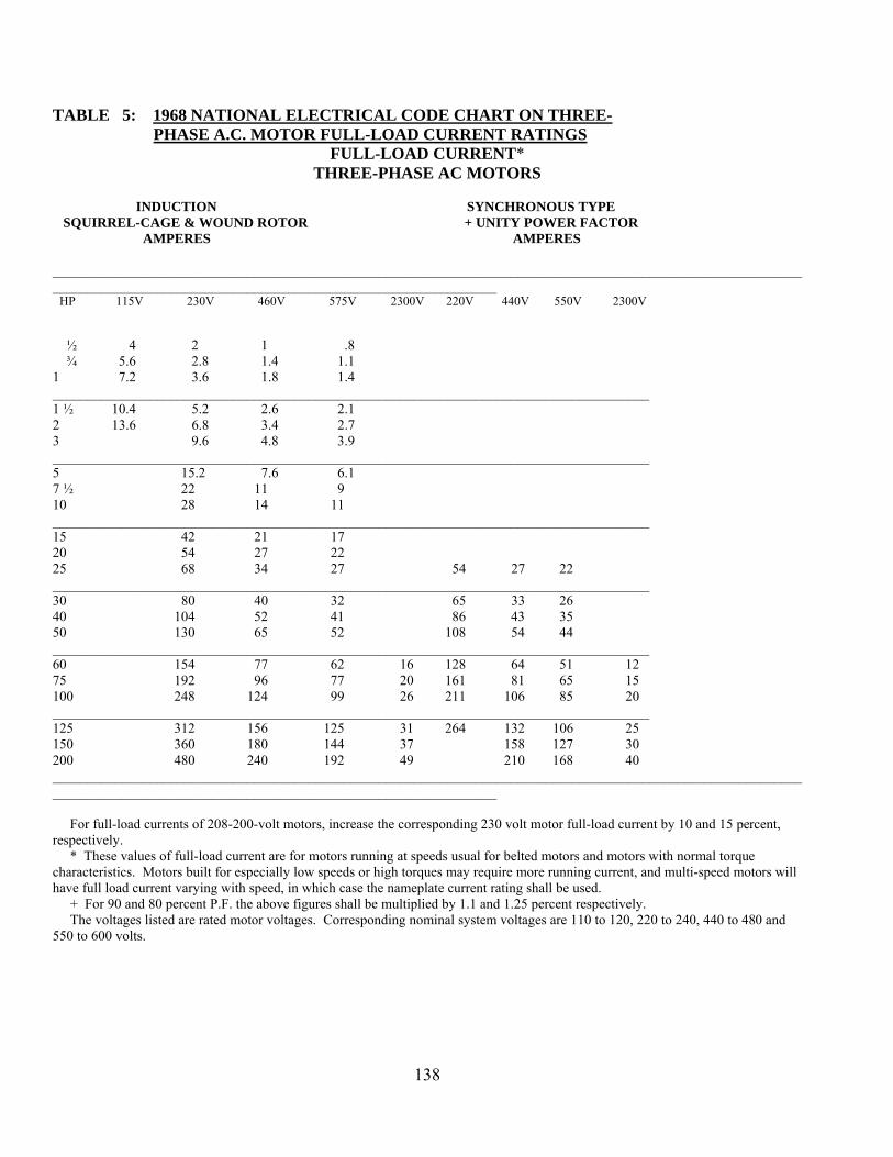
138
TABLE 5: 1968 NATIONAL ELECTRICAL CODE CHART ON THREE- PHASE A.C. MOTOR FULL-LOAD CURRENT RATINGS
FULL-LOAD CURRENT* THREE-PHASE AC MOTORS
INDUCTION SYNCHRONOUS TYPE SQUIRREL-CAGE & WOUND ROTOR + UNITY POWER FACTOR AMPERES AMPERES ____________________________________________________________________________________________________________________________________________________________________________ HP 115V 230V 460V 575V 2300V 220V 440V 550V 2300V ½ 4 2 1 .8 ¾ 5.6 2.8 1.4 1.1 1 7.2 3.6 1.8 1.4 ______________________________________________________________________________________ 1 ½ 10.4 5.2 2.6 2.1 2 13.6 6.8 3.4 2.7 3 9.6 4.8 3.9 ______________________________________________________________________________________ 5 15.2 7.6 6.1 7 ½ 22 11 9 10 28 14 11 ______________________________________________________________________________________ 15 42 21 17 20 54 27 22 25 68 34 27 54 27 22 ______________________________________________________________________________________ 30 80 40 32 65 33 26 40 104 52 41 86 43 35 50 130 65 52 108 54 44 ______________________________________________________________________________________ 60 154 77 62 16 128 64 51 12 75 192 96 77 20 161 81 65 15 100 248 124 99 26 211 106 85 20 ______________________________________________________________________________________ 125 312 156 125 31 264 132 106 25 150 360 180 144 37 158 127 30 200 480 240 192 49 210 168 40 ____________________________________________________________________________________________________________________________________________________________________________ For full-load currents of 208-200-volt motors, increase the corresponding 230 volt motor full-load current by 10 and 15 percent, respectively. * These values of full-load current are for motors running at speeds usual for belted motors and motors with normal torque characteristics. Motors built for especially low speeds or high torques may require more running current, and multi-speed motors will have full load current varying with speed, in which case the nameplate current rating shall be used. + For 90 and 80 percent P.F. the above figures shall be multiplied by 1.1 and 1.25 percent respectively. The voltages listed are rated motor voltages. Corresponding nominal system voltages are 110 to 120, 220 to 240, 440 to 480 and 550 to 600 volts.

139
TABLE 6: TRANSFORMER OVERCURRENT PROTECTION CHART
RECOMMENDED TRANSFORMER MAXIMUM FUSE SIZES
TRANSFORMER PRIMARY AND SECONDARY PRIMARY ONLY SIZE 480V PRI 120V SEC 480V 120V 55 VA ½ A ½ A ½ A 1 A 75 VA ½ A ½ A ½ A 1 A 150 VA 1 A 1 A ½ A 3 A 200 VA 2 A 2 A 1 A 3 A 250 VA 3 A 2 A 1 A 5 A 300 VA 3 A 3 A 1 A 6 A 500 VA 6 A 5 A 2 A 10 A 1.0 KVA 10 A 10 A 5 A 20 A 1.5 KVA 15 A 15 A 6 A 30 A 2.0 KVA 25 A 20 A 10 A 40 A 3.0 KVA 35 A 30 A 15 A 60 A 5.0 KVA 60 A 50 A 25 A 100 A 4160 V 7200 V 12470 V 150 KVA 60 A 30 A 20 A 300 KVA 110 A 60 A 35 A 500 KVA 175 A 100 A 60 A 600 KVA 225 A 125 A 70 A 750 KVA 300 A 150 A 90 A 1000 KVA 350 A 200 A 125 A 2000 KVA 700 A 400 A 250 A

140
NATIONAL ELECTRICAL CODE COMPLIANCE EXAMPLE NO. 1
POWER CABLE AMPACITY, SIZE, AND PROTECTION WHEN NO ELECTRIC MOTORS ARE SERVED.
Circuit Breaker Setting = 1.25 x 24 = 30 amps Cable Ampacity = 30 amps Cable Size 1) Mining Cable = #10 AWG 2) Non-mining Cable = #10 AWG, Type THW 20 KW, 480 Volt, 3-Phase 60 Hz Heater IF.L. = 24 amps

141
NATIONAL ELECTRICAL CODE COMPLIANCE EXAMPLE NO. 2
POWER CABLE AMPACITY, SIZE, AND PROTECTION WHEN ONLY ELECTRIC MOTOR LOADS ARE SERVED
Circuit Breaker Setting 1) Instantaneous Trip-Type a) Std = 7 x 240 + 124 = 1804 amps b) Max = 13 x 240 + 124= 3244 amps 2) Time Inverse or Thermal Trip-Type a) Std = 2.5 x 240 + 124 = 724 amps b) Max = 4 x 240 + 124 = 1084 amps Cable Ampacity = 1.25 x 240 + 124 = 424 amps Cable Size 1) Mining Cable = 350 MCM 2) Non-Mining Cable = 2 paralleled 4/0 Type THW Circuit Breaker Setting Circuit Breaker Setting 1) Instantaneous – Type 1) Instantaneous a) Std = 124 x 7 = 868 amps a) Std = 7 x 240 = 1680 amps b) Max = 124 x 13 = 1,612 amps b) Max = 13 x 240 = 3120 amps 2) Time Inverse or Thermal – Type 2) Thermal a) Std = 124 x 2.5 = 310 amps a) Std = 240 x 2.5 = 600 amps b) Max = 124 x 4 = 496 amps b) Max = 240 x 4 = 960 amps Cable Ampacity = 124 x 1.25 = 155 amps min. Cable Ampacity = 1.25 x 240 = 300 amps Cable Size Cable Size 1) Mining Cable = #2 (163 amps) 1) Mining Cable = 4/0 2) Non-Mining Cable = 2/0 Type THW 2) Non-Mining Cable = 350 MCM Type THW

142
NATIONAL ELECTRICAL CODE COMPLIANCE EXAMPLE NO. 3
POWER CABLE AMPACITY, SIZE AND PROTECTION WHEN A COMBINATION OF ELECTRIC MOTOR LOADS AND NON-ELECTRIC MOTOR LOADS ARE
BEING SERVED
Circuit Breaker Setting
1) Instantaneous a) Std = 7 x 240 + 124 + 24 = 1828 amps b) Max = 13 x 240 + 124 + 24 = 3268 amps
2) Inverse Time or Thermal a) Std = 2.5 x 240 + 124 + 24 = 748 amps b) Maximum = 4 x 240 + 124 + 24 = 1108 amps Cable Ampacity = 1.25 x 240 + 124 + 24 = 448 amps Cable Size 1) Mining Cable = 350 MCM 2) Non-Mining Cable = 2 Paralleled 4/0, Type THW Circuit Breaker Setting Circuit Breaker Setting Circuit Breaker Setting = 30 amps 1) Instantaneous 1) Instantaneous a) Std = 124 x 7 = 868 amps a) Std = 240 x 7 = 1680 amps b) Max = 124 x 13 = 1612 amps b) Max = 240 x 13 = 3120 amps 2) Inverse Time or Thermal 2) Inverse Time or Thermal a) Std = 2.5 x 124 = 310 amps a) Std = 240 x 2.5 = 600 amps b) Max = 4 x 124 = 496 amps b) Max = 240 x 4 = 960 amps Cable Ampacity Cable Ampacity Cable Ampacity = 30 amps = 1.25 x 124 = 155 amps = 1.25 x 240 = 300 amps Cable Size Cable Size Cable Size 1) Mining Cable = #10 1) Mining Cable = #2 1) Mining Cable = # 4/0 2) Non-Mining Cable = #10 2) Non-Mining Cable = 2/0, THW 2)Non-Mining Cable = 350 MCM Type THW
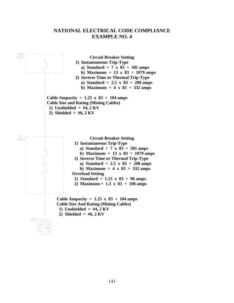
143
NATIONAL ELECTRICAL CODE COMPLIANCE EXAMPLE NO. 4
Circuit Breaker Setting 1) Instantaneous Trip-Type a) Standard = 7 x 83 = 581 amps b) Maximum = 13 x 83 = 1079 amps 2) Inverse Time or Thermal Trip-Type a) Standard = 2.5 x 83 = 208 amps b) Maximum = 4 x 83 = 332 amps Cable Ampacity = 1.25 x 83 = 104 amps Cable Size and Rating (Mining Cables) 1) Unshielded = #4, 2 KV 2) Shielded = #6, 2 KV
Circuit Breaker Setting 1) Instantaneous Trip-Type a) Standard = 7 x 83 = 581 amps b) Maximum = 13 x 83 = 1079 amps 2) Inverse Time or Thermal Trip-Type a) Standard = 2.5 x 83 = 208 amps b) Maximum = 4 x 83 = 332 amps Overload Setting 1) Standard = 1.15 x 83 = 96 amps 2) Maximum = 1.3 x 83 = 108 amps Cable Ampacity = 1.25 x 83 = 104 amps Cable Size And Rating (Mining Cables) 1) Unshielded = #4, 2 KV 2) Shielded = #6, 2 KV

144
NATIONAL ELECTRICAL CODE COMPLIANCE EXAMPLE NO. 5
Circuit Breaker Setting 1) Instantaneous a) Standard = 7 x 83 = 581 amps b) Maximum = 13 x 83 = 1079 amps 2) Inverse Time or Thermal a) Standard = 2.5 x 83 = 208 amps b) Maximum = 4 x 83 = 332 amps Cable Ampacity = 1.25 x 83 + 83 = 187 amps Cable Size and Rating (Mining Cables) 1) Unshielded = #1, 2 KV 2) Shielded = #2, 2 KV Circuit Breaker Setting 1) Instantaneous a) Standard = 7 x 83 = 581 amps b) Maximum = 13 x 83 = 1079 amps 2) Thermal or Inverse time a) Standard = 2.5 x 83 = 208 amps b) Maximum = 4 x 83 = 332 amps O.L. Setting O.L. Setting 1) Standard = 1.15 x 83 = 96 amps 1) Standard = 1.25 x 83 = 104 amps 2) Maximum = 1.3 x 83 = 108 amps 2) Maximum = 1.4 x 83 = 116 amps Cable Ampacity = 1.25 x 83 = 104 amps Cable Ampacity = 1.25 x 83 = 104 amps Cable Size and Rating (Mining Cables) Cable Size and Rating (Mining Cables) 1) Unshielded = #4, 2 KV 1) Unshielded = #4, 2 KV 2) Shielded = #6, 2 KV 2) Shielded = #6, 2 KV

145
NATIONAL ELECTRICAL CODE COMPLIANCE EXAMPLE NO. 6
Circuit Breaker Setting 1) Instantaneous a) Std = 7 x 83 = 581 amps b) Max = 13 x 83 = 1079 amps 2) Time Inverse or Thermal a) Std = 2.5 x 83 = 208 amps b) Max = 4 x 83 =332 amps Cable Ampacity = 1.25 x 83 + 83 + 83 = 270 amps Cable Size & Rating (Mining Cables) 1) Unshielded = 3/0, 2 KV 2) Shielded = 2/0, 2 KV Circuit Breaker Setting 1) Instantaneous a) Std. = 7 x 83 = 581 amps b) Max = 13 x 83 = 1079 amps 2) Thermal a) Std = 2.5 x 83 = 268 amps b) Max = 4 x 83 = 332 amps O.L. 1 O.L. 2 O.L. 3 1) Std = 1.15 x 83 = 96 A 1) Std = 1.25 x 83 = 104 A 1) Std = 1.25 x 83 = 104 A 2) Max = 1.3 x 83 = 108 A 2) Max = 1.4 x 83 = 116 A 2) Max = 1.4 x 83 = 116 A Cable Ampacity = 1.25 x 83 Cable Ampacity = 1.25 x 83 Cable Ampacity = 1.25 x 83 = 104 A = 104 A = 104 A Cable Size & Rating (Mining Cables) Cable Size & Rating (Mining Cables) Cable Size & Rating (Mining Cables) 1) Unshd = #4, 2 KV 1) Unshd = #4, 2 KV 1) Unshd = #4, 2 KV 2) Shd = #6, 2 KV 2) Shd = #6, 2 KV 2) Shd = #6, 2 KV

146
NATIONAL ELECTRIC CODE COMPLIANCE EXAMPLE NO. 7
Circuit Breaker Setting 1) Instantaneous a) Std = 7 x 83 + 83 + 83 = 747 amps b) Max = 13 x 83 + 83 + 83 = 1245 amps 2) Thermal a) Std = 2.5 x 83 + 83 + 83 = 347 amps b) Max = 4 x 83 + 83 + 83 = 498 amps Cable Ampacity = 1.25 x 83 + 83 + 83 = 270 amps Cable Size & Rating (Mining Cables) 1) Unshielded = 3/0, 2 KV 2) Shielded = 2/0, 2 KV Circuit Breaker Setting Circuit Breaker Setting Circuit Breaker Setting 1) Instantaneous 1) Instantaneous 1) Instantaneous a) Std = 7 x 83 = 581 amps a) Std = 7 x 83 = 581 amps a) Std = 7 x 83 = 581 amps b) Max = 13 x83 = 1079 amps b) Max = 13 x 83 = 1079 amps b) Max = 13 x 83 = 1079 amps 2) Thermal 2) Thermal 2) Thermal a) Std = 2.5 x 83 = 208 amps a) Std = 2.5 x 83 = 208 amps a) Std = 208 amps b) Max = 4 x 83 = 322 amps b) Max = 4 x 83 = 322 amps b) Max = 322 amps O.L. 1 O.L. 2 O.L. 3 1) Std = 1.15 x 83 = 96 amps 1) Std = 1.25 x 83 = 104 amps 1) Std = 1.25 x 83 = 104 amps 2) Max = 1.3 x 83 = 108 amps 2) Max = 1.4 x 83 = 116 amps 2) Max = 1.4 x 83 = 116 A Cable Ampacity = 1.25 x 83 Cable Ampacity = 1.25 x 83 Cable Ampacity = 1.25 x 83 = 104 amps = 104 amps = 104 amps Cable Size & Rating (Mining Cables) Cable Size & Rating (Mining Cables) Cable Size & Rating (Mining Cables) 1) Unshd = #4, 2 KV 1) Unshd = #4, 2 KV 1) Unshd = #4, 2 KV 2) Shd = #6, 2 KV 2) Shd = #6, 2 KV 2) Shd = #6. 2 KV

147
NATIONAL ELECTRICAL CODE
1. A location in which hazardous concentrations of flammable gases or vapors exist continuously, intermittently, or periodically under normal operating conditions is classified as:
a. Class I, Division 1 b. Class I, Division 2 c. Class II, Division 1 d. Class II, Division 2
2. A location in which combustible dust is or may be in suspension in the air continuously, intermittently,
or periodically under normal operating conditions in quantities sufficient to produce explosive or ignitable mixtures is classified as:
a. Class I, Division 1 b. Class I, Division 2 c. Class II, Division 1 d. Class II, Division 2
3. A location in which volatile liquids or flammable gases are handled in which hazardous concentrations
of gases or vapors are normally prevented by positive mechanical ventilation, but which might become hazardous through failure or abnormal operation of the ventilation equipment is classified as:
a. Class I, Division 1 b. Class I, Division 2 c. Class II, Division 1 d. Class II, Division 2
4. A location in which combustible dust will not normally be in suspension in air or will not be likely to
be thrown into suspension by the normal operation of equipment or apparatus in quantities sufficient to produce explosive or ignitable mixtures, but where deposits or accumulations of such combustible dust may be sufficient to interfere with the safe dissipation of heat from electric equipment or apparatus; or where such deposits or accumulations of electric equipment or apparatus; or where such deposits or accumulations of combustible dust on, in, or in the vicinity of electric equipment might be ignited by arcs, sparks, or burning material from such equipment is classified as:
a. Class I, Division 1 b. Class I, Division 2 c. Class II, Division 1 d. Class II, Division 2
5. Which of the following wiring methods is not approved for use in Class I, Division 1 locations?
a. Threaded rigid conduit b. Threaded steel intermediate metal conduit c. Electrical metallic tubing d. Type MI cable with proper termination fittings
6. Which of the following wiring methods is not approved for use in Class I, Division 2 locations?
a. Enclosed gasketed busways b. Type PLTC cable c. Rigid metal conduit d. Electrical metallic tubing

148
7. All boxes, fittings, and joints used in Class I, Division 1 locations shall be: a. Threaded and explosion proof b. Approved under Schedule 2 G c. In compliance with AIEE standards d. Waterproof
8. The term that best describes the type of wiring method and equipment used in Class I locations is:
a. Explosion proof b. Dust-ignition-proof c. Watertight d. Oiltight
9. The term that best describes the type of wiring methods and equipment used in Class II locations is: a. Explosion proof b. Dust-ignition-proof c. Watertight d. Oiltight
10. The scope of the National Electrical Code does not include coverage for:
a. Electric conductors and equipment installed within or on public buildings b. Conductors that connect the installation to a supply of electricity c. Installations underground in mines d. Outside conductors on mine property
11. What is the minimum size of power conductor comprising each phase or neutral that shall be permitted
to be connected in parallel? a. 2 AWG b. 1/0 AWG c. 2/0 AWG d. 4/0 AWG
12. Which of the following is the approved equipment grounding conductor color code?
a. White b. Natural Gray c. Black d. Green or green with one or more yellow stripes
13. Ungrounded conductors shall be distinguished by colors other than: a. White, natural gray, or green b. White only c. Green only d. Any color is acceptable
14. What is the ampacity of a #6 AWG, Type XHHW, copper conductor at an ambient temperature of 30o
and with three conductors in a rigid conduit? a. 55 amperes b. 65 amperes c. 70 amperes d. 75 amperes

149
15. What is the ampacity of a #6 AWG, Type THW, copper conductor at an ambient temperature of 40 C and with six conductors in a rigid conduit?
a. 42 amperes b. 52 amperes c. 53 amperes d. 45 amperes
16. What is the minimum acceptable size of rigid conduit to enclose three #2 AWG, Type THWN, copper
conductors? a. ¾ inch b. 1 inch c. 1 ¼ inch d. 1 ½ inch
17. What is the maximum number of 4/0 AWG, Type TW, copper conductors that may be enclosed by a 2
½ inch EMT? a. 3 b. 4 c. 5 d. 6
Questions 18 – 23 are regarding the electric motor specified below (motor nameplate data): 150 HP, Three Phase, 60 Hertz 444 T Frame, 1750 RPM, Code F 460 Volts, 180 Amperes F.L. Continuous Duty, 40o C ambient
18. What is the required ampacity of the branch circuit conductors for this motor? a. 144 amperes b. 180 amperes c. 207 amperes d. 225 amperes
19. What is the minimum size of branch circuit conductors and rigid conduit acceptable for this
application? Assume three copper conductors with an insulation rating of 75o C enclosed in the rigid conduit.
a. 3/0 AWG, 1 ½ inch b. 4/0 AWG, 2 inch c. 4/0 AWG, 2 1/2 inch d. 250 MCM, 2 inch
20. What is the maximum allowable instantaneous-type circuit breaker trip setting to provide branch circuit
overcurrent protection without using exceptions? a. 900 amperes b. 1,260 amperes c. 1,800 amperes d. 2,340 amperes

150
21. What is the maximum allowable inverse-type circuit breaker trip setting to provide branch circuit overcurrent protection without using exceptions?
a. 270 amperes b. 360 ampers c. 450 amperes d. 540 amperes
22. What is the maximum allowable motor running overcurrent protection trip setting without using
exceptions? a. 207 amperes b. 189 amperes c. 198 amperes d. 225 amperes
23. Where the specified instantaneous-type circuit breaker trip setting for motor branch-circuit protection
is not sufficient for the starting of the motor, the setting shall be permitted to be increased to maximum of:
a. 900 amperes b. 1,260 amperes c. 1,800 amperes d. 2,340 amperes
Questions 24 – 30 are regarding the multiple motor feeder circuit shown in Figure 1. The nameplate data of each electric motor is given below. Main Circuit Breaker
Motor Feeder Circuit
Branch Branch Branch Circuit #1 Circuit #2 Circuit #3
M1 M2 M3
O.L. 1 O.L. 2 O.L. 3
Motor 1 Motor 2 Motor 3 Motor 1: 150 HP, Three Phase, 60 Hertz 444 T Frame, 1,750 RPM, Code F 460 Volts, 180 Amperes F.L. Continuous Duty, 40o C Ambient

151
Motor 2: 100 HP, Three Phase, 60 Hertz 405 TS Frame, 1,740 RPM, Code G 460 Volts, 124 Amperes F.L. Continuous Duty, 40o C Ambient Motor 3: 75 HP, Three Phase, 60 Hertz 365 TS Frame, 1,740 RPM 460 Volts, 96 Amperes F.L. Continuous Duty, 1.0 Service Factor
24. What is the minimum size of conductors and rigid conduit for motor branch circuit 2? Assume three copper conductors with an insulation rating of 75o C enclosed in the rigid conduit?
a. 2/0 AWG, 1 ½ inch b. 2/0 AWG, 2 inch c. 1/0 AWG, 1 ¼ inch d. 3/0 AWG, 1 ½ inch
25. What is the maximum allowable instantaneous trip setting for branch circuit 2 overcurrent protection
without exceptions? a. 310 amperes b. 620 amperes c. 868 amperes d. 1,612 amperes
26. What is the maximum allowable trip setting for motor 2 running overcurrent overload protection
without using exceptions? a. 124 amperes b. 136 amperes c. 143 amperes d. 155 amperes
27. What is the minimum conductor size and rigid conduit size and maximum allowable instantaneous trip
setting for branch circuit 3 overcurrent protection? Assume three copper conductors with an insulation rating of 90o C enclosed in the rigid conduit, and take no exception on overcurrent protection settings.
a. #2 AWG, 1-inch, 240 amperes b. #2 AWG, 1 1/4-inch, 672 amperes c. 1/0 AWG, 1-inch, 672 amperes d. #2 AWG, 1-inch, 1,248 amperes
28. What is the maximum allowable motor running overcurrent (overload) protection trip setting for motor
3? a. 96 amperes b. 106 amperes c. 110 amperes d. 120 amperes

152
29. What is the required ampacity of the motor feeder conductors, and what is the minimum conductor size that will satisfy this requirement? Assume three copper conductors with an insulation rating of 90o C in a rigid conduit.
a. 400 amperes, 500 MCM b. 445 amperes, 600 MCM c. 445 amperes, 700 MCM d. 500 amperes, 700 MCM
30. What is the maximum allowable instantaneous trip setting for the motor feeder conductors without
considering exceptions? a. 1,260 amperes b. 1,480 amperes c. 2,560 amperes d. 2,800 amperes

153
ANSWER SHEET FOR TEST #6
NATIONAL ELECTRICAL CODE 1. a 16. c 2. c 17. a 3. b 18. d 4. d 19. c 5. c 20. b 6. d 21. c 7. a 22. a 8. a 23. d 9. b 24. b 10. c 25. c 11. b 26. c 12. d 27. b 13. a 28. c 14. b 29. b 15. d 30. b

154
TEST #7
PRACTICAL EXAMINATION
WIRING DIAGRAMS AND METERS

155
UTAH MINE ELECETRICIAN CERTIFICATION EXAMINATION STUDY GUIDE
VII. TEST #7 - Wiring Diagrams and Electrical Meters Outline
A. Demonstrate the ability to wire electric circuits and systems from a schematic diagram 1. Dual motor belt starter 2. Typical substation high-voltage electrical distribution system 3. Typical high-voltage electrical distribution system electrical protective device
interconnections B. Demonstrate the ability to determine mine power feeder cable ampacity from a chart and
properly set overload protection 1. Current transformer ratio and connection 2. Phase time overcurrent relay tap setting
C. Particular attention must be paid to keeping substation ground field and mine ground field isolated by a minimum of 25 feet. No surface lightning arresters shall be connected to the mine ground grid
D. Demonstrate the ability to properly use digital multimeters and clamp-on ammeters to measure circuit resistance, voltage, and current.
1. All legally required and prudent safety precautions must be taken anddemonstrated. 2. Proper safeguards must be utilized while testing and troubleshooting energized circuits.
Test circuit voltages will not exceed 120 volts. 3. Properly select digital multimeter mode and range to 120 VAC nominal circuit voltage. 4. Properly select digital multimeter mode and range to measure circuit load resistance. 5. Properly select digital clamp-on ammeter mode and range to measure circuit current
draw.

156
SAMPLE TEST CIRCUIT AND REQUIRED
ELECTRICAL CIRCUIT MEASUREMENTS Load Resistance Measurement 120 VAC, 1, 60 Hz Hot Neutral Ground Circuit Disconnected Black White Green Test Terminal Block Set on Ω Terminal Load R = ? Enclosure Load

157
Voltage and Current Measurements 120 VAC, 1, 60 Hz Hot Neutral Ground Circuit Connected and Energized I? Test Terminal Block Set on volts Test Load Enclosure