surface morphology and beta-phase formation of single ... · beta-phase content based on response...
TRANSCRIPT

ORIGINAL RESEARCH
Surface morphology and beta-phase formation of single polyvinylidenefluoride (PVDF) composite nanofibers
Ehsan Ghafari1 & Xiaodong Jiang1& Na Lu1,2,3
Received: 2 June 2017 /Revised: 26 June 2017 /Accepted: 6 July 2017# Springer International Publishing AG, part of Springer Nature 2017
AbstractThis study has developed a reliable model to design and engineer PVDF nanofiber in terms of both morphological and fraction ofbeta-phase content based on response surface methodology (RSM). The model was further used to assess the effect of eachindividual electrospinning processing parameter as well as their interdependences on the properties of electrospun PVDFnanofibers. Our experimental results highly agreed with the modeling. The results indicated that both morphological andcrystalline properties of PVDF are highly affected by electrospinning process parameters, particularly the fraction of beta-phase content. A beadless PVDF nanofiber with the maximum fraction of the beta phase was achieved through a numericaloptimization process.
Keywords PVDF . Nanofiber . Bead-free . Electrospinning . Response surface method . Optimization
1 Introduction
Nowadays, energy harvesting is one of the most promisingtechnologies due to concerns about the availability of non-renewable energy sources in the future [1–5]. Piezoelectricmaterials have been widely used as the primary element ofmany energy harvesters, to capture the energy from the vibra-tion movements [6–9]. Poly (vinylidene fluoride) (PVDF)nanofibers have shown good ability to harvest the mechanicalforce under high strain conditions, due to their excellent flex-ibility and process simplicity [10]. PVDF has been widelyinvestigated due to its piezoelectric and ferroelectric proper-ties as well as its high flexibility, high durability, and good
mechanical properties. The molecular structure of PVDF in-volves the repeated monomer unit (−CH2CF2−)n. PVDF is asemi crystalline polymer with the four distinctive crystal struc-tures which can be divided into the polar and non-polarphases. Among them, three polar crystal forms exist (β, γ,and δ phases), where β-phase (TTTT) is highly polar com-pared to the other two phases. The non-polar α-phase (TGTG′), however, is the most common and thermodynamically sta-ble phase at ambient temperature and pressure [11, 12]. Theβ-phase of PVDF is responsible for its electroactive propertiessuch as ferroelectric, piezoelectric, and pyroelectric properties.The PVDF polymer chains in the unit cell of β-phase arearranged in a way that all the dipoles are aligned in a parallelmanner leading to a net dipole moment, which is the strongestamong all the phases [13–16]. Hence, the enhancement of betaphase of PVDF is essential for many applications.
Electrospinning is a widely used processing method to fab-ricate flexible PVDF nanofibers since it is simple, efficient,and cost effective. It has been reported that electrospun PVDFnanofiber results in the formation of the piezoelectric β-phase[17–20]. The electrospinning process involves applying a highelectrical field and elongation force on nanofiber jet; it elimi-nates the need for post-treatment processes including electricpoling and mechanical stretching. Despite electrospinning
* Na [email protected]
1 Lyles School of Civil Engineering, Sustainable Materials andRenewable Technology (SMART) Laboratory, Purdue University,West Lafayette, IN, USA
2 School of Materials Engineering, Purdue University, WestLafayette, IN, USA
3 Birck Nanotechnology Center, Purdue University, WestLafayette, IN, USA
Advanced Composites and Hybrid Materialshttps://doi.org/10.1007/s42114-017-0016-z
method appears to be technically straightforward, processingvariables are not well understood and optimized in order tofabricate PVDF nanofibers with the desired properties [21].For instance, the effects of each individual electrospinningprocess parameter on the properties of PVDF nanofiber havealready been reported [18, 22–25]. The interdependences ofeach processing parameter on nanofiber characteristics havenot been studied, since the conventional model only involveschanging one of the electrospinning process parameters whilekeeping the others fixed at certain values. As results, the con-ventional methods do not provide a reliable model to predictand optimize the properties of PVDF nanofiber, and they aretime-consuming and costly. Therefore, it is important to de-velop a comprehensive and reliable model to elucidate theeffect of the electrospinning processing parameters on themorphology and the beta-phase formation of electrospunPVDF nanofiber. On the modeling part, the response surfacemethodology (RSM) has been approved as a powerful exper-imental design technique for the modeling and analysis ofproblems in which a response of interest is influenced byseveral variables [26–30]; however, the validity of using thismethod on PVDF nanofiber process has never been examined.To fill this knowledge gap, this paper aims to investigate theeffect of electrospinning process parameters on the morphol-ogy and crystallinity of PVDF nanofiber. A RSM model isproposed to predict the size, the probability of the bead for-mation, and the fraction of beta-phase content of electrospunPVDF nanofiber. In addition, the proposed model was used toassess the effect of each electrospinning process parameter aswell as the interdependences among all parameters. Finally, amulti-objective numerical optimization technique was used toachieve a bead-free PVDF nanofiber, simultaneous with themaximum of beta-phase content.
2 Experimental program
2.1 Materials and sample preparation
PVDF pellet (Mw = 275,000), N,N-dimethylformamide(DMF, Sigma 99.5%), and acetone (Sigma, 99.7%) werepurchased from Sigma-Aldrich. In this study, PVDF solu-tion was prepared by dissolving PVDF pellets in solventmixtures of DMF/acetone. The solution was heated at70 °C for 1 h followed by 5 h stirring at room temperature.The homogenous PVDF solution was then added to the 10-ml plastic syringe which was placed in a syringe pump.The positive voltage in range of 7.5 to 13.6 kV was appliedto the needle to form Taylor cone (Table 1). The variousfeeding rate of the solution was adjusted to obtain a stableliquid jet. The nanofibers were spawned on a groundedrotating drum collector, which was placed at a distance of10 cm from the tip of the needle.
2.2 Development of RSM model
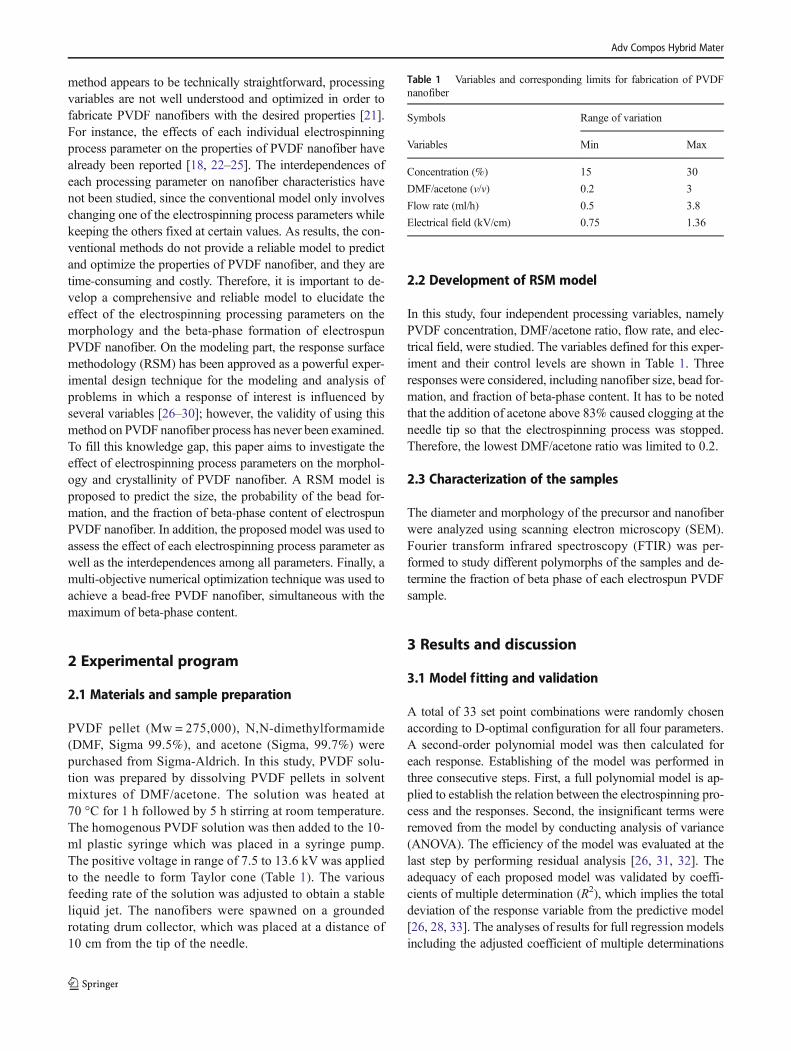
In this study, four independent processing variables, namelyPVDF concentration, DMF/acetone ratio, flow rate, and elec-trical field, were studied. The variables defined for this exper-iment and their control levels are shown in Table 1. Threeresponses were considered, including nanofiber size, bead for-mation, and fraction of beta-phase content. It has to be notedthat the addition of acetone above 83% caused clogging at theneedle tip so that the electrospinning process was stopped.Therefore, the lowest DMF/acetone ratio was limited to 0.2.
2.3 Characterization of the samples
The diameter and morphology of the precursor and nanofiberwere analyzed using scanning electron microscopy (SEM).Fourier transform infrared spectroscopy (FTIR) was per-formed to study different polymorphs of the samples and de-termine the fraction of beta phase of each electrospun PVDFsample.
3 Results and discussion
3.1 Model fitting and validation
A total of 33 set point combinations were randomly chosenaccording to D-optimal configuration for all four parameters.A second-order polynomial model was then calculated foreach response. Establishing of the model was performed inthree consecutive steps. First, a full polynomial model is ap-plied to establish the relation between the electrospinning pro-cess and the responses. Second, the insignificant terms wereremoved from the model by conducting analysis of variance(ANOVA). The efficiency of the model was evaluated at thelast step by performing residual analysis [26, 31, 32]. Theadequacy of each proposed model was validated by coeffi-cients of multiple determination (R2), which implies the totaldeviation of the response variable from the predictive model[26, 28, 33]. The analyses of results for full regression modelsincluding the adjusted coefficient of multiple determinations
Table 1 Variables and corresponding limits for fabrication of PVDFnanofiber
Symbols Range of variation
Variables Min Max
Concentration (%) 15 30
DMF/acetone (v/v) 0.2 3
Flow rate (ml/h) 0.5 3.8
Electrical field (kV/cm) 0.75 1.36
Adv Compos Hybrid Mater

(Adj-R2), the predicted coefficient of multiple determinations(Pre-R2), the lack of fit, and the model P value are given inTable 2. The obtained correlation coefficients for fiber size,bead formation, and fraction of beta phase were R2 = 0.95,R2 = 0.92, and R2 = 0.94, respectively. These high values ofcorrelation coefficient validate the adequacy of the modelused to navigate the design space. ANOVA analysis was alsoperformed to further evaluate the significance of the model.The F values 21.1, 16.8, and 88.7 were obtained for fiber size,bead formation, and fraction of beta phase, respectively, indi-cating that the models are significant. There is only a 0.01%chance that such a large F value could occur due to noise.
The adequacy of the model was verified by performing alack-of-fit test (Table 2). The desired result is an insignificantlack of fit, presented by a value greater than 0.05 [34]. All theP values obtained by ANOVA implied that the lack of fit is notsignificant compared to the reference.
3.2 Morphology of PVDF nanofiber
Parameters affecting on the morphology and crystallinityof PVDF nanofiber can be classified into two groups in-cluding solution properties and electrospinning processparameters. The PVDF nanofiber size and formation ofthe beads are the two main characteristics that need tobe controlled during the electrospinning process. SEM
was used for visual analysis of the PVDF nanofiber mor-phology. The diameter and size distribution of the fiberswere analyzed using ImageJ software. Figures 1 and 2shows the morphology of two electrospun PVDF nanofi-ber mesh with the same concentration (25%) and differentDMF/acetone ratios. The average diameter of nanofiber insample 1 and sample 2 was around 87 and 438 nm, re-spectively. The SEM images of other two samples withthe same PVDF concentration (27.5%) are presented inFig. 3. Figure 3a shows a beadless PVDF nanofiber whileFig. 3b exhibits a high number of beads at the same con-centration. The concentration of PVDF was reportedwidely as the most significant factor to minimize thebeads in PVDF nanofiber [18, 25]; however, the substan-tial difference in nanofiber size (Figs. 1 and 2) and beadformation (Fig. 3) for the samples with the same concen-tration of PVDF pellets implies other electrospinning pro-cesses have more effects on morphology of electrospunnanofiber. In order to better present the complex relationsbetween the parameters and responses, several 3D inter-action surface graphs along with the trace plots obtainedfrom RSM model were used as presented in Figs. 4 and 8.
Once the model was validated, the effect of each parameteron the response was systematically investigated. The ANOVAanalysis was used to assess the effect of individual parametersas well as the interaction of variables on responses. The effectof variation of concentration and DMF/acetone ratio on nano-fiber size is shown in Fig. 4. The higher concentration resultedin higher solution viscosity and stronger intermolecular inter-actions which led to larger nanofiber size. However, theamount of acetone plays a critical role in controlling the fibersize. For a constant electrical field and flow rate, the higherDMF/acetone ratio led to a finer fiber size; as shown in Fig. 2,higher acetone content increases the evaporation rate. In orderto have a better understanding of each individual constituent
Fig. 1 PVDF nanofibers at concentration of 25%, DMF/acetone—3; a SEM image. b Fiber size distribution
Table 2 Results for full regression models
Responses Adj-R2 Pre-R2 F value Lack of fit ModelP value
Fiber size 0.95 0.89 21.1 0.32 < 0.0001
Bead formation 0.92 0.85 16.8 0.46 < 0.0001
Beta-phase content 0.94 0.90 88.7 0.23 < 0.0001
Adv Compos Hybrid Mater

effect on the response, a trace plot was used. A constituenteffect curve displays how a model predicts that the responsewill change as the constituent is decreased or increased fromits level in the reference mixture [28]. Figure 5 shows theeffect of variation of all constituents on PVDF nanofiber size.The slope of the plot indicates the sensitivity of the response interms of each constituent. The results indicated that higherelectrical field leads to the formation of the fine fibers. In fact,applying the higher voltage might impose a higher chargedensity on the surface of nanofiber jet. This induces a largerelongation force to the fiber jet which results in a finer nano-fiber size. As it can be seen, flow rate curve showed almost ahorizontal trend, which implies that the nanofiber size is notvery sensitive to this parameter.
The formation of beads has been widely reported in theelectrospinning process [35–37], and it has been considered
as the main drawback of the electrospun fibers [35]. The for-mation of bead-free nanofibers is favorable in almost all ap-plications of electrospun nanofibers. The formation of beadsin electrospun nanofibers is mostly related to the instability ofthe jet of polymer solution [38, 39]. In this study, the amountsof beads in microstructure of the nanofiber were measuredquantitatively using ImageJ software. Figure 6 shows the var-iation of the bead formation in PVDF nanofiber as functionsof concentration and DMF/acetone ratio. The results indicatedthat the amounts of beads increase with the decrease of con-centration. In general, the lower concentration increased therisk of bead formation in PVDF nanofiber. The low viscoussolution favors the formation of beads in PVDF nanofiber dueto lack of sufficient polymer entanglement [40]. The resultsindicated the number of beads was reduced drastically for thesolution with the concentration above 25%. However, several
Fig. 3 Scanning electron microscopy image of nanofibers with concentration of 27.5%. a A beadless nanofiber. b PVDF nanofiber with a high numberof beads
Fig. 2 PVDF nanofibers at concentration of 25%, DMF/acetone—1; a SEM image. b Fiber size distribution
Adv Compos Hybrid Mater

electrospun nanofiber samples with high concentration ofPVDF pellets (more than 25%) exhibited considerable amountof beads, implying that the solution concentration itself doesnot necessarily result in a bead-free nanofiber. The DMF/acetone was to be found very effective in decreasing theamount of beads in PVDF nanofiber. However, the increasein DMF/acetone ratio results in nanofiber with increasedbeads may be attributed to the incomplete solvent evaporation.Indeed, the high volatility of acetone increased the evapora-tion rate of the solution which causes the jet to dry faster andthus impeding the electrospun jet breaking up into droplets
[25]. Also, the addition of acetone reduces the surface tensionof the solution so that beaded fibers can be converted intosmooth fibers [41]. Hence, when the acetone concentrationin the solution increased up to 60%, the number of beadsreduced drastically, allowing to achieve a bead-free nanofiberat concentration even lower than 25%.
3.3 Beta-phase formation
The ferroelectric and piezoelectric properties of PVDF nano-fiber are attributed to the fraction of β-phase. FTIR analysis is
Fig. 7 3D fraction of beta phase plot as function of concentration andDMF/acetone
Fig. 6 3D bead formation plot as function of concentration and DMF/acetone
Fig. 5 Trace plot of PVDF nanofiber size
Fig. 4 3D fiber size plot as function of concentration and DMF/acetone
Adv Compos Hybrid Mater

mostly used to quantify the electroactive phase content ofPVDF. Assuming that FTIR absorption follows the Lambert-Beer law, the relative fraction of the β-phase in a samplecontaining just α and β PVDF is (Eq. 1) [42]:
Fβ ¼ Aβ
Kβ=Kα
� �Aα þ Aβ
ð1Þ
where F(β) represents the phase content; Aα and Aβ are theabsorbance at 766 and 840 cm−1; and Kα and Kβ are the ab-sorption coefficients at the respective wavenumber, whichvalues are 6.1 × 10⁴ and 7.7 × 104 cm2 mol−1, respectively.
The fraction of β-phase as function of concentration andDMF/acetone ratio is presented in Fig. 7. The results indicatedthat the fraction of β-phase is considerably decreased by re-ducing the DMF/acetone ratio. This might be due to the
solvent evaporation rate which can be divided into three levelsincluding low, intermediate, and high evaporation rates. It hasbeen reported that low evaporation rates result mainly in theα-phase which are thermodynamically more favorable, whileintermediate rates in a mixture of α and β and high evapora-tion rates in theα-phase are kinetically more favorable [43]. Infact, adding more acetone increases the evaporation rate of thesolution, since it has a lower evaporation temperature, and thisleads to the formation of more α-phase in PVDF nanofibersamples. The trace plot (Fig. 8) clearly confirms the signifi-cant effect of the acetone content on fraction of beta-phasecontent. As can be seen, the fraction of beta phase increasedby increasing the concentration of PVDF pellets. High con-centration of PVDF decreases the evaporation rate of the so-lution resulting in a formation of a high fraction beta-phasecontent. The simultaneous interaction effects of low concen-tration (15%) and high volume of acetone content (83%)
Fig. 9 Response surface plots of the Derringer’s desirability function incorrelation with a variation of concentration and DMF/acetone ratio
Table 4 Optimum parameters for the proposed criteria
Constituents and responses
M1 M2
Concentration (%) 27.5 26
DMF/acetone (v/v) 1.49 1.25
Flow rate (ml/h) 2 1.5
Electrical field (kV/cm) 1.36 1.36
Fiber size (nm) 265 295
Beads (%) 0.09 0.09
Beta phase (%) 75 71
Desirability 0.98 0.96
Table 3 Optimization of individual responses for a bead-free PVDFnanofiber with the highest fraction of beta phase
Responses and variables Lower Upper Criteria
Goal Importance
Concentration (%) 15 30 In range 5
DMF/acetone (v/v) 0.2 3 In range 5
Flow rate (ml/h) 0.5 3.8 In range 5
Electrical field (kV/cm) 0.75 1.36 In range 5
Fiber size (nm) 58 300 In range 5
Beads (%) 0.1 2 Minimize 5
Beta phase (%) 0.48 0.76 Maximize 5
Fig. 8 Trace plot for fraction of beta phase in PVDF nanofiber
Adv Compos Hybrid Mater

reduce the beta-phase content below 50%. Figure 8 shows thatthe fraction of beta phase can be enhanced by applying higherelectrical field. The fraction ofβ-phase increases with increas-ing electrical field for all PVDF nanofiber samples. It has to benoted that this effect was more pronounced for the samplessubjected at higher voltage. At high voltage, the electrospunjet is subjected to the elongation force because of an increasednumber of charges. In addition, a high electric field is inducedbetween the needle and conductive drum collector at highvoltage. This electrical field acts as the polling process whichcan further enhance the fraction of beta phase in PVDF nano-fiber samples [44]. As presented in trace plot, flow rate doesnot show any significant effect on the beta-phase fraction.
3.4 Numerical optimization
A numerical optimization was conducted to develop a bead-free PVDF nanofiber with the maximum fraction of the betaphase. The global desirability function [45] was used to opti-mize any combination of one or more goals (Eq. 2):
D ¼ dr11 � dr22 � dr33 �…� drnn� �1=∑ri ¼ ∏
n
i¼1diri
� �1=∑rið2Þ
where n is the number of responses included in the optimiza-tion and ri is the relative importance of each individual func-tion di. Importance (ri) varies from 1 to 5, respectively from
Fig. 11 The FTIR curve of PVDFnanofiber samples optimized bymulti-objective optimizationprocess
Fig. 10 The SEM images of PVDF nanofiber samples optimized by multi-objective optimization process
Adv Compos Hybrid Mater

least to most important. Individual desirability functions (di)range between 0, for a completely undesired response, and 1,for a fully desired response. For a value of D close to 1, thecombination of different criteria is globally optimal so theresponse values are near to the target values [28, 29].
In this study, two criteria have been defined to achieve abead-free PVDF nanofiber with the highest fraction of betaphase. Table 3 shows all parameters and responses with theirlimits range, required for conducting numerical optimization.Figure 9 presents a two-response optimization zone, in whichthe highest beta-phase fraction and lowest number of beadswere found to reach the highest desirability function. Twodifferent optimal solutions, with the desirability of the func-tions ranging from 0.94 to 0.96, were obtained from the multi-objective optimization process. The predicted optimal solu-tion and electrospinning parameters (M1,M2) and correspond-ing response values are shown in Table 4. The morphology ofboth optimal solution is presented in Fig. 10. The SEM pictureshows the formation of beadless electrospun PVDF nanofiberfor both optimal samples. The fraction of beta phase was de-termined by FTIR technique as shown in Fig. 11. The nano-fiber sizes of M1 and M2 are 265 and 295 nm, respectively,which are aligned with the defined range for the optimizationprocess. The samples exhibited 75 and 71% of fraction ofbeta-phase content, respectively, which satisfy the minimumcriteria in the optimization process. Results confirmed that theexperimental values are in good agreement with the valuespredicted by the proposed model.
4 Conclusions
This study proposed a robust model based on RSM method topredict the characteristics of PVDF nanofiber in terms of bothmorphological and fraction of beta-phase content. The modelwas further used to assess the effect of each individualelectrospinning process parameter as well as the combined ef-fect on the electrospun PVDF properties. A numerical optimi-zation was conducted to achieve a beadless PVDF nanofiberwith the maximum fraction of the beta phase. The RSM modelwas established which provides a thorough examination ofPVDF nanofiber over the selected range of the electrospinningprocess parameters. The high values of coefficients of multipledeterminations (R2) showed the accuracy of the model to pre-dict the characteristics of PVDF nanofiber in terms of bothmorphological and fraction of beta-phase content. TheANOVA results also confirmed that the inclusions of all modelparameters are statistically significant based on very low Pvalue. The higher concentration led to larger nanofiber sizedue to the higher solution viscosity and stronger intermolecularinteractions. Also, for a constant electrical field and flow rate,the higher DMF/acetone ratio led to a finer fiber size, as higheracetone content increases the evaporation rate. The results
indicated the number of beads was reduced drastically for thesolution with the concentration above 25%. However, the re-sults revealed that the high concentration solution itself doesnot necessarily result in a bead-free nanofiber. The increase inDMF/acetone ratio results in nanofiber characterized by morebeads which might be due to the incomplete solvent evapora-tion. The fraction of β-phase is considerably affected by evap-oration rate so that the high concentration of PVDF and DMF/acetone decreases the evaporation rate of the solution resultingin a formation of a high fraction beta-phase content. A numer-ical optimization was also conducted to achieve a beadlessPVDF nanofiber with the maximum fraction of the beta phase.The accuracy of the obtained results was confirmed by execut-ing a new series of experimental tests.
Funding information The authors at Purdue University are grateful to thefunding supports from National Science Foundation (NSF CMMI–1560834) and Purdue Research Foundation.
References
1. Ghafari E, Witkoske E, Liu Y, Zhang C, Jiang X, Bukowski A,Kucukgok B, Lundstrom M, Ferguson IT, Lu N (2017) Waste en-ergy harvesting using III-nitrides materials. III-Nitride materials,devices and nano-structures p 37
2. Lu N, Ferguson I (2013) III-nitrides for energy production: photo-voltaic and thermoelectric applications. Semicond Sci Technol28(7):074023
3. Feng Y, Jiang X, Ghafari E, Kucukgok B, Zhang C, Ferguson I, LuN (2017) Metal oxides for thermoelectric power generation andbeyond. Adv Composites Sci
4. Hussain B, Raja M, Lu N, Ferguson I (2013) Applications andsynthesis of zinc oxide: an emerging wide bandgap material. inHigh Capacity Optical Networks and Enabling Technologies(HONET-CNS), 2013 10th International Conference on. IEEE
5. Tong T, Fu D, Levander AX, Schaff WJ, Pantha BN, Lu N, Liu B,Ferguson I, Zhang R, Lin JY (2013) Suppression of thermal con-ductivity in InxGa1− xN alloys by nanometer-scale disorder. ApplPhys Lett 102(12):121906
6. Wang Z, Song J (2006) Piezoelectric nanogenerators based on zincoxide nanowire arrays. Science 312(5771):242–246
7. Gu L, Cui N, Cheng L, XuQ, Bai S, YuanM,WuW, Liu J, Zhao Y,Ma F (2012) Flexible fiber nanogenerator with 209Voutput voltagedirectly powers a light-emitting diode. Nano Lett 13(1):91–94
8. Zhang G, Xu S, Shi Y (2011) Electromechanical coupling of leadzirconate titanate nanofibres. IETMicro&Nano Letters 6(1):59–61
9. Sun Z, Zhang L, Dang F, Liu Y, Fei Z, Shao Q, Lin H, Guo J, XiangL, Yerra N (2017) Experimental and simulation understanding ofmorphology controlled barium titanate nanoparticles under co-adsorption of surfactants. Cryst Eng Comm
10. Chang C, Tran VH, Wang J, Fuh Y-K, Lin L (2010) Direct-writepiezoelectric polymeric nanogenerator with high energy conversionefficiency. Nano Lett 10(2):726–731
11. Li M, Wondergem H, Spijkman M, Asadi K, Katsouras I, Blom P,De LeeuwD (2013) Revisiting the [delta]-phase of poly (vinylidenefluoride) for solution-processed ferroelectric thin films. Nat Mater12(5):433
12. Aqeel SM, Huanga Z,Walton J, Baker C, Falkner D, Liu Z,Wang Z(2017) Advanced functional polyvinylidene fluoride (PVDF)/polyacrilonitrile (PAN) organic semiconductor assisted by aligned
Adv Compos Hybrid Mater

nanocarbon toward energy storage and conversion. AdvComposites Sci
13. Bodkhe S, Rajesh P, Kamle S, Verma V (2014) Beta-phase en-hancement in polyvinylidene fluoride through filler addition: com-paring cellulose with carbon nanotubes and clay. J Polym Res21(5):434
14. Bassiri-Gharb N, Fujii I, Hong E, Trolier-McKinstry S, Taylor DV,Damjanovic D (2007) Domain wall contributions to the propertiesof piezoelectric thin films. J Electroceram 19(1):49–67
15. Liu Z, Pan CT, Lin LW, Li HW, KeCA, Huang JC,Wang PS (2013)Mechanical properties of piezoelectric PVDF/MWCNT fibers pre-pared by flat/hollow cylindrical near-field electrospinning process.in Nano/Micro Engineered and Molecular Systems (NEMS), 20138th IEEE International Conference on. IEEE
16. Pu J, Yan X, Jiang Y, Chang C, Lin L (2010) Piezoelectric actuationof direct-write electrospun fibers. Sensors Actuators A Phys 164(1):131–136
17. Guo H-F, Li Z-S, Dong S-W, Chen W-J, Deng L, Wang Y-F, YingD-J (2012) Piezoelectric PU/PVDF electrospun scaffolds forwound healing applications. Colloids Surf B: Biointerfaces 96:29–36
18. Cozza E, Monticelli O, Marsano E, Cebe P (2013) On theelectrospinning of PVDF: influence of the experimental conditionson the nanofiber properties. Polym Int 62(1):41–48
19. Sencadas V, Ribeiro C, Bdikin I, Kholkin A, Lanceros-Mendez S(2012) Local piezoelectric response of single poly (vinylidene fluo-ride) electrospun fibers. Phys Status Solidi A 209(12):2605–2609
20. Damaraju S, Wu S, JaffeM, Arinzeh T (2013) Structural changes inPVDF fibers due to electrospinning and its effect on biologicalfunction. Biomed Mater 8(4):045007
21. Ghafari E, Feng Y, Liu Y, Ferguson I, Lu N (2017) Investigatingprocess-structure relations of ZnO nanofiber via electrospinningmethod. Compos Part B 116:40–21
22. Lei T, Yu L, Zheng G, Wang L, Wu D, Sun D (2015)Electrospinning-induced preferred dipole orientation in PVDF fi-bers. J Mater Sci 50(12):4342–4347
23. Baqeri M, Abolhasani M, Mozdianfard M, Guo Q, Oroumei A,Naebe M (2015) Influence of processing conditions on polymor-phic behavior, crystallinity, and morphology of electrospun poly(VInylidene fluoride) nanofibers. J Appl Polym Sci 132(30)
24. Nascimento A (2014) Electrospinning of nanofiber composite fromsolution of poly (vinylidene fluoride)/carbon nanotube. RevistaPolitécnica 33(1)
25. Costa L, Bretas R, Gregorio R (2010) Effect of solution concentra-tion on the electrospray/electrospinning transition and on the crys-talline phase of PVDF. Mater Sci Appl 1(04):247
26. Montgomery DC (2005) Design and analysis of experiments: re-sponse surface method and designs. New Jersey
27. Ghafari E, Costa H, Júlio E (2013) Development of ultra highperformance self compacting concrete. in Proceedings of the fifthNorth American conference on the SCC design and use of self-consolidating concrete. Chicago, USA
28. Ghafari E, Hugo C, Júlio E (2014) RSM-based model to predict theperformance of self-compacting UHPC reinforced with hybrid steelmicro-fibers. Constr Build Mater 66(0):375–383
29. Ghafari E, Costa H, Júlio E (2015) Statistical mixture design ap-proach for eco-efficient UHPC. Cem Concr Compos 55(0):17–25
30. Alyamac K, Ghafari E, Ince R (2017) Development of eco-efficientself-compacting concrete with waste marble powder using the re-sponse surface method. J Clean Prod 144:192–202
31. Ghafari E, Bandarabadi M, Costa H, Júlio E (2012) Design ofUHPC using artificial neural networks in 10th international sympo-sium on brittle matrix composites. Warsaw, Poland
32. Ghafari E, Bandarabadi M, Costa H, Júlio E (2015) Prediction offresh and hardened state properties of UHPC: comparative study ofstatistical mixture design and an artificial neural network model. JMater Civ Eng
33. Ghafari E, Costa H, Júlio E (2014) New robust design approach foroptmized sustainable UHPC. in The Fourth International fibCongress. Mumbai
34. Simon MJ, Lagergren ES, Wathne LG (1999) Optimizing high-performance concrete mixtures using statistical response surfacemethods. in International Symposium on Utilization of High-Strength/High-Performance Concrete. Oslo, Norway
35. Liu Y, He J-H, Yu J, Zeng H (2008) Controlling numbers and sizesof beads in electrospun nanofibers. Polym Int 57(4):632–636
36. Miyoshi T, Toyohara K, Minematsu H (2005) Preparation of ultra-fine fibrous zein membranes via electrospinning. Polym Int 54(8):1187–1190
37. Yuan X, Zhang Y, Dong C, Sheng J (2004)Morphology of ultrafinepolysulfone fibers prepared by electrospinning. Polym Int 53(11):1704–1710
38. Yarin A (1993) Free liquid jets and films: hydrodynamics and rhe-ology. Longman Publishing Group
39. Entov V, Shmaryan LE (1997) Numerical modeling of the capillarybreakup of jets of polymeric liquids. Fluid dynamics 32(5):696–703
40. Correia D, Gonçalves R, Ribeiro C, Sencadas V, Botelho G,Ribelles J, Lanceros-Méndez S (2014) Electrosprayed poly (vinyl-idene fluoride) microparticles for tissue engineering applications.RSC Adv 4(62):33013–33021
41. Li Z, Wang C (2013) Effects of working parameters onelectrospinning, in one-dimensional nanostructures. Springer p15–28
42. Martins P, Lopes AC, Lanceros-Mendez S (2014) Electroactivephases of poly (vinylidene fluoride): determination, processingand applications. Prog Polym Sci 39(4):683–706
43. Chinaglia D, Gregorio R, Stefanello J, Pisani Altafim R, Wirges W,Wang F, Gerhard R (2010) Influence of the solvent evaporation rateon the crystalline phases of solution-cast poly (vinylidene fluoride)films. J Appl Polym Sci 116(2):785–791
44. Andrew J, Clarke DR (2008) Effect of electrospinning on the fer-roelectric phase content of polyvinylidene difluoride fibers.Langmuir 24(3):670–672
45. Derringer GC, Suich R (1980) Simultaneous optimization of sever-al response variables. J Qual Technol 12(4):214–219
Adv Compos Hybrid Mater