surface morphology and electron transport properties of
TRANSCRIPT

Surface Morphology and Electron Transport Properties Bull. Korean Chem. Soc. 2010, Vol. 31, No. 10 2967DOI 10.5012/bkcs.2010.31.10.2967
Surface Morphology and Electron Transport Properties of Composite Films by Poly-N-vinylcarbazole/Polyaniline
C. Basavaraja, Eun Ae Jo, Bong Sung Kim, H. Mallikarjuna,† and Do Sung Huh*
Department of Chemistry and Institute of Basic Science, Inje University, Gimhae, Kyungnam 621-749, Korea*E-mail: [email protected]
†Department of Chemistry, A.G.M. Rural Engineering College, Hubli-281107, Karnataka, IndiaReceived July 31, 2010, Accepted September 2, 2010
Poly-N-vinylcarbazole/polyaniline (PVK-PANI) composites are synthesized by varying target loading concentrations of aniline (0.025 - 0.1 M). The surface morphology of the composites is studied by scanning electron microscopy (SEM) and atomic force microscopy (AFM). The temperature-dependent DC conductivity of PVK-PANI composite films was studied at the temperature range of 300 - 500 K. The data suggest that the conductivity increase with an increase in aniline concentration in the composite with an increase in temperature. Further based on the conductivity behavior we can suggest that the PVK-PANI composites show a semiconducting behavior with a positive temperature coefficient of resistivity (TCR). The enhanced conductivity and the positive TCR of the PVK-PANI composite films may be due to the strong interaction between PANI and PVK in the composite films.
Key Words: DC conductivity, Morphology, Polyaniline, Poly(N-vinylcarbazole)
Introduction
Conducting polymer nanocomposites (CPC) have been ob-tained by the dispersion of electrically conducting fillers, such as carbon nanoparticles,1-6 metal particles,7,8 or carbon nano-tubes,9-12 into a large variety of insulating polymer matrices. Dis-persion is a critical step because the resultant CPC can have very different electrical properties, depending on processing tem-perature,5 blending time,1 and particle/matrix interactions.13,14 Controlling the effect of these parameters enables determining the appropriate balance between dispersion and aggregation phenomena to prevent the formation of micro-agglomerates or conductive pathway breakage. The wide choice of polymer/ filler combinations and the adjustment of conducting filler con-tent (relative to percolation threshold) make numerous appli-cations possible.
Among different polymeric materials, poly-N-vinyl carbazole (PVK) has been widely used in light-emitting diodes and xero-graphy, and generally as an electro-optically active polymer because of its specific photo-physical properties.15-19 An im-portant advancement in this direction is the preparation of the hybrid nanocomposite materials of these polymers using selec-tive inorganic components.20-24 The polymerization reactions of N-vinylcarbazole (VC) can be performed in bulk, in solution, in suspension, or in precipitation.25-28 PVK is a lightweight material with chemical and thermal stabilities. It has excellent electrical properties that make it highly useful in electronic devices.
Polyaniline (PANI) is one of the most potentially useful conducting polymers, possessing unique electrical properties that can be reversibly controlled by charge-transfer doping and protonation. The chemical method is one of the most common synthesizing processes for PANI production.29 PANI is a parti-cularly promising material for commercial applications because of its good environmental stability, facile synthesis, and higher
conductivity compared with other conducting polymers.30,31 Re-cently, a number of studies on the chemical synthesis of PANI have been conducted; the synthesis was realized in the presence of polymer and oligomer acids with various structures.32-37 In addition, PANI has received considerable attention because of its unique reversible proton doping, high electrical conductivity, ease of preparation, and low cost. The demand for high-quality materials for electromagnetic compatibility has alarmingly in-creased. The production of radar-absorbing material is directly related to the development of new materials for applications involving stringent requirements in microwave reflection su-ppression.38, 39
In this report, a template synthesis is performed with the aim of imparting new properties from PVK to PANI to im-prove the existing properties of the latter, such as its ability to form films and remove defects in the molecular structure of PVK. PVK-PANI polymer films were prepared using different target loading concentrations of aniline in the range of 0.025 - 0.1 M. The enhancement of electrical conductivity in the 300 - 500 K temperature range reveals semiconducting behavior with positive temperature coefficient of resistivity (TCR). Further-more, the apparent activation energy was determined. The Arr-henius equation shows the dependence of the thermal rate pro-cess of electron transport within these temperature ranges.
Experimental Section
Materials. AR grade N-vinylcarbazole (VC), aniline, ammo-nium per sulfate (APS), ferric chloride (FeCl3), chloroform (CHCl3), and absolute ethanol (C2H5OH) were purchased from Sigma-Aldrich. All solutions were prepared in aqueous media using deionized water.
Synthesis of PANI. PANI was synthesized by in situ poly-merization in the presence of APS as initiator oxidant. The ty-pical preparation process is as follows:40-42 The aniline monomer

2968 Bull. Korean Chem. Soc. 2010, Vol. 31, No. 10 C. Basavaraja et al.
0 - 5 oCAPS
(b)
PVK -Aniline
Mixing
(a)
+
Aniline PVK
CH3ONa
NMP
PVK -PANIThin films
(c)
Aniline PVK
Mixing
(a)
PVK-Aniline
PVK-PANIThin films
APS0 - 5 oC
CH3ONa
NMP
(c)
(b)
Figure 1. The overall experimental scheme for the preparation of the PVK-PANI composite film.
was first dissolved in water, and the solution was sonicated for 30 min to obtain a uniform suspension. The APS solution was then slowly added, followed by cooling of the complete solu-tion to ‒10 oC. The resultant mixture was allowed to react in an ice bath for 20 h. The precipitated powder was filtered and washed with distilled water and methanol until the filtrate be-came colorless, and then dried in a vacuum at room temperature for 24 h.
Synthesis of PVK. VC was used as monomer and FeCl3 as oxidizing agent to synthesize PVK.43-45 For the synthesis of PVK, the monomer (1 g of VC) was dissolved in 5 mL chloro-form. The oxidizing agent (1.0 g of FeCl3) was dissolved in 25 mL chloroform, and the resultant solution was filtered using filter paper. The VC solution in chloroform was then slowly added into the FeCl3 solution, maintaining temperature at 0 - 4 oC using an ice chamber for about 12 h. Ethanol was added into the mixture at room temperature, and a white precipitate was obtained. This precipitate was recovered from the reaction vessel, filtered, and washed using ethanol and diethylether at least three times to eliminate the oxidizing agent. The powder obtained was washed in distilled water and acetone several times and then dried for a few days.
Synthesis of PVK-PANI composites. For the synthesis of the composite, 1 g of VC monomer was dissolved in 5 mL chloro-form. One gram of FeCl3 oxidizing agent was dissolved in 25 mL chloroform, and the resultant solution was filtered using filter paper. The VC solution in chloroform was slowly added into the FeCl3 solution, maintaining temperature at 0 - 4 oC using an ice chamber for about 20 h. This solution was later transferred to a 500 mL beaker, to which aniline was also added. The resul-tant mixture was sonicated for about 1 h. About 25 mL of ethanol was then added into the mixture at room temperature, and the obtained precipitate was sonicated for approximately 30 min. Subsequently, the 0.1 M APS solution prepared in water was slowly added. The mixture was then cooled to 0 - 4 oC in an ice chamber and allowed to react for 20 h.46,47 The precipi-tated powder was filtered and washed with distilled water and methanol until the filtrate became colorless. It was then dried in a vacuum at room temperature for 24 h. The target mass load-ing of the aniline monomer in the composites was varied from 0.025 - 0.1 M. The composites are abbreviated as PVK-y, where y refers to the molar concentration of aniline in the poly-merization reaction. Aniline concentrations of 0.025, 0.05, 0.075, and 0.10 M were included in each composite of PVK- 025, PVK-05, PVK-075, and PVK-10, respectively.
Preparation of the PVK-PANI composite films. For the pre-paration of the composite films, 41,42,48 the powder was treated with a solution of sodium ethoxide (C2H5ONa) and ethanol, and magnetically stirred at room temperature for 12 h. Finally, the precipitate was filtered and repeatedly washed with ethanol and stored in a desiccator for 4 h at room temperature. Then, 1 - 2 g of finely ground powder was taken and added to 30 mL of NMP solution magnetically stirred for 24 h at room temperature. The concentrated solution was placed into a Petri dish, and the NMP solvent was allowed to evaporate at 45 oC for 48 h. The films were placed in distilled water, rinsed with ethanol, and dried at room temperature for another 24 h. To obtain solvent- free films, the residual NMP was removed by three cycles of
doping using 1 M HCl solution for 18 h and de-doped by 0.1 M NH4OH solution for another 18 h at room temperature. The re-sultant NMP-free composite films were cleaned in deionized water and dried at room temperature for 24 h. A digital micro-meter was used to measure the thickness of the polymer films, which was about 30 µm a value of approximately 5% accuracy. The overall experimental scheme for the preparation of the PVK-PANI composite film is introduced in Figure 1.
Surface morphology of the PVK-PANI composites. The mor-phology of the composite films was investigated by SEM (Philips XL-30 ESEM). AFM image analysis was carried out using a Digital Instruments D3100 AFM with a Nanoscope IIIa con-troller operating in air at a constant relative humidity of about 60%.
DC conductivity measurements. DC electric measurements for the obtained composite films were performed within the 300 - 500 K temperature range using the four-probe technique, with a Keithly 224 constant current source and a Keithly 617 digital electrometer.
Results and Discussion
Surface morphology of the PVK-PANI composite films. Figures 2(a)-2(d) show the SEM images of PVK-025, PVK-05, PVK-075, and PVK-10 composite films, respectively. The fi-gures show that the surface morphologies of the PVK-PANI composites introduced in this research do not differ to a great extent from PANI or its composites, as reported elsewhere.49-51 However, PVK-025 film shown in Figure 2(a) reveals a rela-tively non-uniform hard surface with large clusters. In PVK-05 and -075 shown in Figures 2(b) and (c), the clusters disappear to form an aggregated surface that appears nearly uniform with small particles. The surface of PVK-10 composite film appears more or less similar to those of PVK-05 and -075. The clusters/ particles disappear to form more aggregated structures. Thus, the surface of PVK-PANI films exhibits a change from cluster to aggregated structure during composite formation by increasing aniline concentration in the composite as shown in Figure 2(d).

Surface Morphology and Electron Transport Properties Bull. Korean Chem. Soc. 2010, Vol. 31, No. 10 2969
(a)(a) (b)(b)
(c)(c) (d)(d)
Figure 2. SEM image of PVK-PANI composite films. (a) SEM imageof PVK-025, (b) SEM image of PVK-05, (c) SEM image of PVK-075, and (d) SEM image of PVK-10 composite films.
0 1.00 2.00 3.00 µm
3.00
2.00
1.00
0
0 1.00 2.00 3.00 µm
3.00
2.00
1.00
0
(a) (b)
0 1.00 2.00 3.00 µm
3.00
2.00
1.00
0
0 0.25 0.50 0.75 1.00 µm
1.00
0.75
0.50
0.25
0
(c) (d)
0.0 0.5 1.0 1.5 2.0 2.5 3.0
X (µm)
PVK-10225
150
75
0225
150
75
0225
150
75
0
Z (n
m) PVK-05
PVK-025
(e)
Figure 3. Topographic images obtained by AFM for composite films PVK-025 (a), PVK-05 (b), and PVK-10 (c). An extended image for PVK-05 is given in (d). (e) shows section plots for PVK-025, PVK-05, and PVK-10 composite films.
Table 1. Temperature coefficient of resistivity (TCR) for PVK-PANI composite films
Temperature (K)
Temperature coefficient of resistivity (TCR)
PVK-025 PVK-05 PVK-10
308 - 403403 - 503
0.010030.0095
0.00930.00873
0.009040.0086
The surface morphology was also studied by AFM image analysis. Figure 3 shows a two-dimensional (2D; 3 × 3 µm) topo-graphy of the films PVK-025 (a), PVK-05 (b), and PVK-10 (c). Figure 3(d) shows a two-dimensional (2D; 2 × 1 µm) topo-graphy, which is an extended portion of PVK-05 composite film. Their section plots are shown in Figure 3(e). The surface mor-phology of PVK-075 is not introduced in this study because it is similar to that of PVK-05. Comparing these figures, PVK-025 shows irregular structures in the form of fibers, whereas PVK-05 shows structures in the form of clusters. The cluster-like struc-tures on the surface of PVK-025 and -05 may be due to PVK in the presence of PANI. The surface of PVK-10 is more or less uniform, which may be attributed to the high concentration of PANI in the composite films. The section plots for PVK-PANI are shown in Figure 3(e). The typical structures present in PVK- 025 and -05 composite shows more surface roughness, which appear to have decreased in PVK-05. The surface of PVK-10 is almost uniform. The increase in surface uniformity can be attributed to the presence of PANI in the PVK-PANI composite films. The amorphousness of PANI makes for nearly uniform composite films.
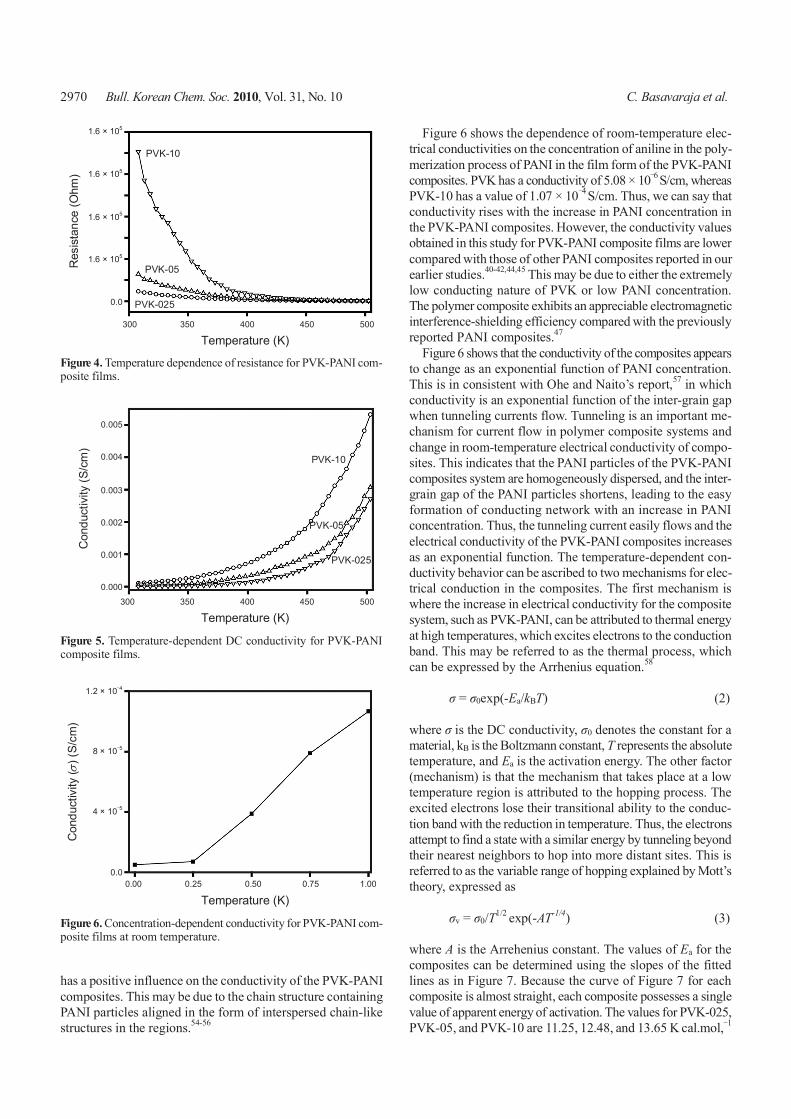
DC electrical conductivity in the PVK-PANI composite films. To understand charge transport mechanism in the PVK-PANI composite films, the temperature-dependent electrical conduc-tivity was studied for all compositions. Figure 4 shows the va-riation in electrical resistance with temperature for PVK-025, PVK-05, and PVK-10. The electrical resistance exponentially decreases with temperature, similar to semiconducting behavior. Electrical resistance rises with the increase in PANI concent-ration. TCR was determined from the variation in electrical re-sistivity with temperature using the following relationship: 52,53
TCR = (1/ρT1)(∆ρ/∆T) (1)
where ∆ρ = ρ(T1)- ρ(T2) and ∆T = T2 - T1. Table 1 shows the calculated values of TCR in two different temperature ranges, one at 308 - 403 K and the other at 403 - 503 K for PVK-025,
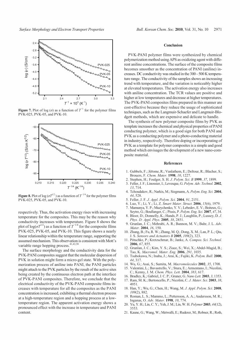
PVK-05, and PVK-10 composite films. The values of TCR in either range exhibit positive values, which are higher at low tem-perature ranges and lower at high temperature ranges. Figure 5 shows the electrical conductivity with temperature for the PVK- PANI composite films. The conductivity data suggest that PANI
2970 Bull. Korean Chem. Soc. 2010, Vol. 31, No. 10 C. Basavaraja et al.
300 350 400 450 500
Temperature (K)
PVK-10
1.6 × 10⁵
1.6 × 10⁵
1.6 × 10⁵
1.6 × 10⁵
0.0
Res
ista
nce
(Ohm
)
PVK-05
PVK-025
Figure 4. Temperature dependence of resistance for PVK-PANI com-posite films.
300 350 400 450 500
Temperature (K)
PVK-10
0.005
0.004
0.003
0.002
0.001
0.000
Con
duct
ivity
(S/c
m)
PVK-05
PVK-025
Figure 5. Temperature-dependent DC conductivity for PVK-PANI composite films.
0.00 0.25 0.50 0.75 1.00
Temperature (K)
Con
duct
ivity
( )
(S/c
m)
σ
1.2 × 10‒4
8 × 10‒5
4 × 10‒5
0.0
Figure 6. Concentration-dependent conductivity for PVK-PANI com-posite films at room temperature.
has a positive influence on the conductivity of the PVK-PANI composites. This may be due to the chain structure containing PANI particles aligned in the form of interspersed chain-like structures in the regions.54-56
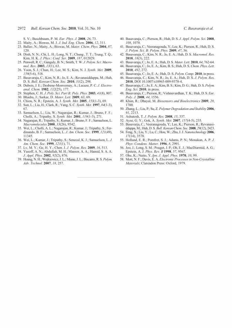
Figure 6 shows the dependence of room-temperature elec-trical conductivities on the concentration of aniline in the poly-merization process of PANI in the film form of the PVK-PANI composites. PVK has a conductivity of 5.08 × 10‒6 S/cm, whereas PVK-10 has a value of 1.07 × 10‒4 S/cm. Thus, we can say that conductivity rises with the increase in PANI concentration in the PVK-PANI composites. However, the conductivity values obtained in this study for PVK-PANI composite films are lower compared with those of other PANI composites reported in our earlier studies.40-42,44,45 This may be due to either the extremely low conducting nature of PVK or low PANI concentration. The polymer composite exhibits an appreciable electromagnetic interference-shielding efficiency compared with the previously reported PANI composites.47
Figure 6 shows that the conductivity of the composites appears to change as an exponential function of PANI concentration. This is in consistent with Ohe and Naito’s report,57 in which conductivity is an exponential function of the inter-grain gap when tunneling currents flow. Tunneling is an important me-chanism for current flow in polymer composite systems and change in room-temperature electrical conductivity of compo-sites. This indicates that the PANI particles of the PVK-PANI composites system are homogeneously dispersed, and the inter- grain gap of the PANI particles shortens, leading to the easy formation of conducting network with an increase in PANI concentration. Thus, the tunneling current easily flows and the electrical conductivity of the PVK-PANI composites increases as an exponential function. The temperature-dependent con-ductivity behavior can be ascribed to two mechanisms for elec-trical conduction in the composites. The first mechanism is where the increase in electrical conductivity for the composite system, such as PVK-PANI, can be attributed to thermal energy at high temperatures, which excites electrons to the conduction band. This may be referred to as the thermal process, which can be expressed by the Arrhenius equation.58
σ = σ0exp(-Ea/kBT) (2)
where σ is the DC conductivity, σ0 denotes the constant for a material, kB is the Boltzmann constant, T represents the absolute temperature, and Ea is the activation energy. The other factor (mechanism) is that the mechanism that takes place at a low temperature region is attributed to the hopping process. The excited electrons lose their transitional ability to the conduc-tion band with the reduction in temperature. Thus, the electrons attempt to find a state with a similar energy by tunneling beyond their nearest neighbors to hop into more distant sites. This is referred to as the variable range of hopping explained by Mott’s theory, expressed as
σv = σ0/T1/2 exp(-AT-1/4) (3)
where A is the Arrehenius constant. The values of Ea for the composites can be determined using the slopes of the fitted lines as in Figure 7. Because the curve of Figure 7 for each composite is almost straight, each composite possesses a single value of apparent energy of activation. The values for PVK-025, PVK-05, and PVK-10 are 11.25, 12.48, and 13.65 K cal.mol,‒1
Surface Morphology and Electron Transport Properties Bull. Korean Chem. Soc. 2010, Vol. 31, No. 10 2971
2.1 2.4 2.7 3.0 3.3
T ‒1 × 10³ (K‒1)
‒2.4
‒2.8
‒3.2
‒3.6
‒4.0
‒4.4
‒4.8
‒5.2
log
( ) (
S/cm
)σ
PVK-10
PVK-025
PVK-05
Figure 7. Plot of log (σ) as a function of T ‒1 for the polymer films PVK-025, PVK-05, and PVK-10.
0.210 0.215 0.220 0.225 0.230 0.235 0.240
T ‒1/4 (K‒1/4)
‒50
‒60
‒70
‒80
‒90
log
( T1
/2) (
S/cm
K1/
2 )σ
PVK-10
PVK-025
PVK-05
Figure 8. Plot of log (σT1/2 ) as a function of T ‒1/4 for the polymer filmsPVK-025, PVK-05, and PVK-10.
respectively. Thus, the activation energy rises with increasing temperature for the composites. This may be the reason why conductivity increases with temperature. Figure 8 shows the plot of log(σT1/2) as a function of T ‒1/4 for the composite films PVK-025, PVK-05, and PVK-10. This figure shows a nearly linear relationship within the temperature range, supporting the assumed mechanism. This observation is consistent with Mott’s variable range hopping process.41,42,58
The surface morphology and the conductivity data for the PVK-PANI composites suggest that the molecular dispersion of PVK in solution might form a micro-gel state. With the poly-merization process of aniline into PANI, the PANI particles might attach to the PVK particles by the result of the active sites being created by the continuous electron path at the interface of PVK-PANI composites. Therefore, we conclude that the electrical conductivity of the PVK-PANI composite films in-creases with temperature for all the composites as the PANI concentration is increased, exhibiting a thermal electron process at a high-temperature region and a hopping process at a low- temperature region. The apparent activation energy shows a pronounced effect with the increase in temperature and PANI content.
Conclusion
PVK-PANI polymer films were synthesized by chemical polymerization method using APS as oxidizing agent with diffe-rent aniline concentrations. The surface of the composite films becomes smoother as the concentration of PANI (aniline) in-creases. DC conductivity was studied in the 300 - 500 K tempera-ture range. The conductivity of the samples shows an increasing trend with temperature, and the variation is noticeably higher at elevated temperatures. The activation energy also increases with aniline concentration. The TCR values are positive and higher at low temperatures and decrease at higher temperatures. The PVK-PANI composites films prepared in this manner are cost-effective because they reduce the usage of sophisticated techniques, such as the Langmuir-Schaefer and Langmuir-Blo-dgett methods, which are expensive and delicate to handle.
The synthesis of new polymer composite films by PVK as template increases the chemical and physical properties of PANI conducting polymer, which is a good sign for both PANI and PVK as a conducting polymer and a photo-conducting material in industry, respectively. Therefore doping or incorporating of PVK as a template for polymer composites is a simple and good method which envisages the development of a new nano-com-posite material.
References
1. Gubbels, F.; Jèřome, R.; Vanlathem, E.; Deltour, R.; Blacher, S.; Brouers, F. Chem. Mater. 1998, 10, 1227.
2. Stephen, H.; Foulger, S. H. J. Polym. Sci. B 1999, 37, 1899. 3. Feller, J. F.; Linossier, I.; Levesque, G. Polym. Adv. Technol. 2002,
13, 714. 4. Tchoudakov, R.; Narkis, M.; Siegmann, A. Polym. Eng. Sci. 2004,
44, 528. 5. Feller, J. F. J. Appl. Polym. Sci. 2004, 91, 2151. 6. Luo, Y.; Li, Y.; Li, Z. Smart Mater. Struct. 2006, 15(6), 1979. 7. Mamunya, Y. P.; Muzychenko, Y. V.; Lebedev, E. V.; Boiteux, G.;
Seytre, G.; Boullanger, C.; Pissis, P. Polym. Eng. Sci. 2007, 47, 34. 8. Bloor, D.; Donnelly, K.; Hands, P. J.; Laughlin, P.; Lussey, D. J.
Phys. D: Appl. Phys. 2005, 38, 2851. 9. Grunlan, J. C.; Mehrabi, A. R.; Bannon, M. V.; Bahr, J. L. Adv.
Mater. 2004, 16, 150.10. Zhang, B.; Fu, R. W.; Zhang, M. Q.; Dong, X. M.; Lan, P. L.; Qiu,
J. S. Sensors and Actuators B 2005, 109(2), 323.11. Pötschke, P.; Kretzschmar, B.; Janke, A. Compos. Sci. Technol.
2006, 67, 855.12. Grunlan, J. C.; Kim, Y. S.; Ziaee, S.; Wei, X.; Abdel-Magid, B.;
Tao, K. Macromol. Mater. Eng. 2006, 291, 1035.13. Tsubokawa, N.; Inaba, J.; Arai, K.; Fujiki, K. Polym. Bull. 2000,
44, 317.14. Wu, G.; Asai, S.; Sumita, M. Macromolecules 2002, 35, 1708.15. Valentini, L.; Bavastrello, V.; Stura, E.; Armentano, I.; Nicolini,
C.; Kenny, J. M. Chem. Phys. Lett. 2004, 383, 617.16. Bradley, K.; Gabriel, J. C. P.; Gruner, G. Nano Lett. 2003, 3, 1353.17. Ram, M. K.; Bertoncello, P.; Nicolini, C. J. Mater. Sci. 2003, 38,
4951.18. Han, Y.; Wu, G.; Chen, H.; Wang, M. J. Appl. Polym. Sci. 2008,
109(2), 882.19. Roman, L. S.; Mammo, L.; Pettersson, A. A.; Andersson, M. R.;
Inganas, O. Adv. Mater. 1998, 10, 774.20. Yu, Y. H.; Lin, C. Y.; Yeh, J. M.; Lin, W. H. Polymer 2003, 44(12),
3553.21. Kaune, G.; Wang, W.; Metwalli, E.; Ruderer, M.; Robner, R.; Roth,
2972 Bull. Korean Chem. Soc. 2010, Vol. 31, No. 10 C. Basavaraja et al.
S. V.; Buschbaum, P. M. Eur. Phys. J. 2008, 26, 73.22. Maity, A.; Biswas, M. J. J. Ind. Eng. Chem. 2006, 12, 311.23. Ballav, N.; Maity, A.; Biswas, M. Mater. Chem. Phys. 2004, 87,
120.24. Dinh, N. N.; Chi, L. H.; Long, N. T.; Chung , T. T.; Trung, T. Q.;
Kim, H. K. J. Phys.: Conf. Ser. 2009, 187, 012029.25. Penwell, R. C.; Ganguly, B. N.; Smith, T. W. J. Polym. Sci: Macro-
mol. Rev. 2003, 13(1), 63.26. Yoon, S. J.; Chun, H.; Lee, M. S.; Kim, N. J. Synth. Met. 2009,
159(5-6), 518.27. Basavaraja, C.; Kim, N. R.; Jo, E. A.; Revanasiddappa, M.; Huh,
D. S. Bull. Korean Chem. Soc. 2010, 31(2), 298.28. Dubois, J. E.; Desbene-Monvernay, A.; Lacaze, P. C. J. Electro-
anal. Chem. 1982, 132(25), 177.29. Stephen, C. H. J. Poly. Sci. Part B: Poly. Phys. 2003, 41(8), 807.30. Bhadra, J.; Sarkar, D. Mater. Lett. 2009, 63, 69.31. Chiou, N. R.; Epstein, A. J. Synth. Met. 2005, 153(1-3), 69.32. Sun, L.; Liu, H.; Clark, R.; Yang, S. C. Synth. Met. 1997, 84(1-3),
67.33. Samuelson, L.; Liu, W.; Nagarajan, R.; Kumar, J.; Bruno, F. F.;
Cholli, A.; Tripathy, S. Synth. Met. 2001, 119(1-3), 271.34. Nagarajan, R.; Tripathy, S.; Kumar, J.; Bruno, F. F.; Samuelson, L.
Macromolecules 2000, 33(26), 9542.35. Wei, L.; Cholli, A. L.; Nagarajan, R.; Kumar, J.; Tripathy, S.; Fer-
dinando, B. F.; Samuelson, L. J. Am. Chem. Soc. 1999, 121(49), 11345.
36. Wei, L.; Kumar, J.; Tripathy, S.; Senecal, K. J.; Samuelson, L. J. Am. Chem. Soc. 1999, 121(1), 71.
37. Lv, M. Y.; Ge, H. Y.; Chen. J. J. Polym. Res. 2009, 16, 513.38. Yusoff, A. N.; Abdullah, M. H.; Mansor, A. A.; Hamid, S. A. A.
J. Appl. Phys. 2002, 92(2), 876.39. Hoang, N. H.; Wojkiewicz, J. L.; Miane, J. L.; Biscarro, R. S. Polym.
Adv. Technol. 2007, 18, 257.
40. Basavaraja, C.; Pierson, R.; Huh, D. S. J. Appl. Polym. Sci. 2008, 108, 1070.
41. Basavaraja, C.; Veeranagouda, Y.; Lee, K.; Pierson, R.; Huh, D. S. J. Polym. Sci. B: Polym. Phys. 2009, 47, 36.
42. Basavaraja, C.; Kim, N. R.; Jo, E. A.; Huh, D. S. Macromol. Res. 2010, 18(3), 222.
43. Basavaraja, C.; Jo, E. A.; Huh, D. S. Mater. Lett. 2010, 64, 762-64.44. Basavaraja, C.; Jo, E. A.; Kim, B. S.; Huh, D. S. Chem. Phys. Lett.
2010, 492, 272.45. Basavaraja, C.; Jo, E. A.; Huh, D. S. Polym. Comp. 2010, in press.46. Basavaraja, C.; Kim, N. R.; Jo, E. A.; Huh, D. S. J. Polym. Res.
2010, DOI 10.1007/s10965-009-9378-4.47. Basavaraja, C.; Jo, E. A.; Kim, B. S.; Kim, D. G.; Huh, D. S. Polym.
Eng. Sci. 2010, in press.48. Basavaraja, C.; Pierson, R.; Vishnuvardhan, T. K.; Huh, D. S. Eur.
Poly. J. 2008, 44, 1556.49. Khan, R.; Dhayal, M. Biosensors and Bioelectronics 2009, 20,
1700.50. Zhang, L.; Liu, P.; Su, Z. Polymer Degradation and Stability 2006,
91, 2213.51. Ashutosh, T. J. Polym. Res. 2008, 15, 337. 52. Ayse, G. Y.; Gok, A. Synth. Met. 2007, 157(4-5), 235.53. Basavarja, C.; Veeranagouda, Y.; Lee, K.; Pierson, R.; Revanasi-
ddappa, M.; Huh, D. S. Bull. Korean Chem. Soc. 2008, 29(12), 2423.54. Feng, X.; Liu, Y.; Lu, C.; Hou, W.; Zhu, J. J. Nanotechnology 2006,
17(14), 3578.55. Holland, E. R.; Pomfret, S. J.; Adams, P. N.; Monakan, A. P. J.
Phys: Condens. Matter. 1996, 8, 2991.56. Joo, J.; Long, S. M.; Pouget, J. P.; Oh, E. J.; MacDiarmid, A. G.;
Epstein, A. J. Phys. Rev. B 1998, 57, 9567.57. Ohe, K.; Naito, Y. Jpn. J. Appl. Phys. 1970, 10, 99.58. Mott, N. F.; Davis, E. A. Electronic Processes in Non-Crystalline
Materials; Clarendon Press: Oxford, 1979.