surface reaf. vehicle dec2000 recommended practice
TRANSCRIPT
SAE Technical Standards Board Rules provide that: “This report is published by SAE to advance the state of technical and engineering sciences. The use of this report is entirelyvoluntary, and its applicability and suitability for any particular use, including any patent infringement arising therefrom, is the sole responsibility of the user.”
SAE reviews each technical report at least every five years at which time it may be reaffirmed, revised, or cancelled. SAE invites your written comments and suggestions.
TO PLACE A DOCUMENT ORDER: (724) 776-4970 FAX: (724) 776-0790SAE WEB ADDRESS http://www.sae.org
Copyright 2000 Society of Automotive Engineers, Inc.All rights reserved. Printed in U.S.A.
SURFACEVEHICLE
400 Commonwealth Drive, Warrendale, PA 15096-0001RECOMMENDEDPRACTICE
Submitted for recognition as an American National Standard
J901REAF.
DEC2000
Issued 1964-06Reaffirmed 2000-12
Superseding J901 MAR1995
Universal Joints and Driveshafts—Nomenclature—Terminology—Application
1. Scope—The following definitions and illustrations are intended to establish common nomenclature andterminology for universal joints and driveshafts used in various driveline applications. In addition, usefulguidelines are included for the application of universal joints and driveshafts. For more specific details, seeUniversal Joint and Driveshaft Design Manual, AE-7.
2. References
2.1 Applicable Publication—The following publication forms a part of this specification to the extent specifiedherein.
2.1.1 SAE PUBLICATION—Available from SAE, 400 Commonwealth Drive, Warrendale, PA 15096-0001.
AE-7 Universal Joint and Driveshaft Design Manual
3. Definitions—Basic Driveline Terms:
3.1 Driveline—An assembly of one or more driveshafts with provisions for axial movement, which transmitstorque and/or rotary motion at a fixed or varying angular relationship from one shaft to another.
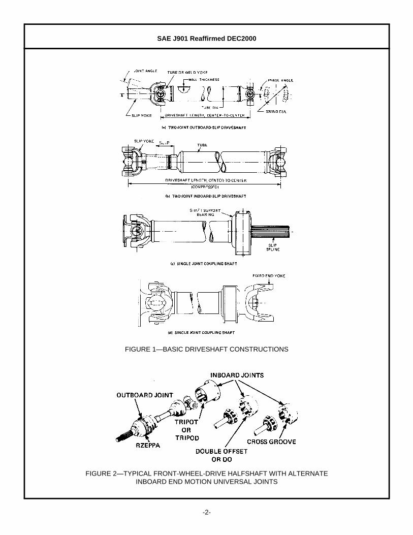
3.2 Driveshaft—An assembly of one or two universal joints connected to a solid or tubular shaft member (seeFigure 1).
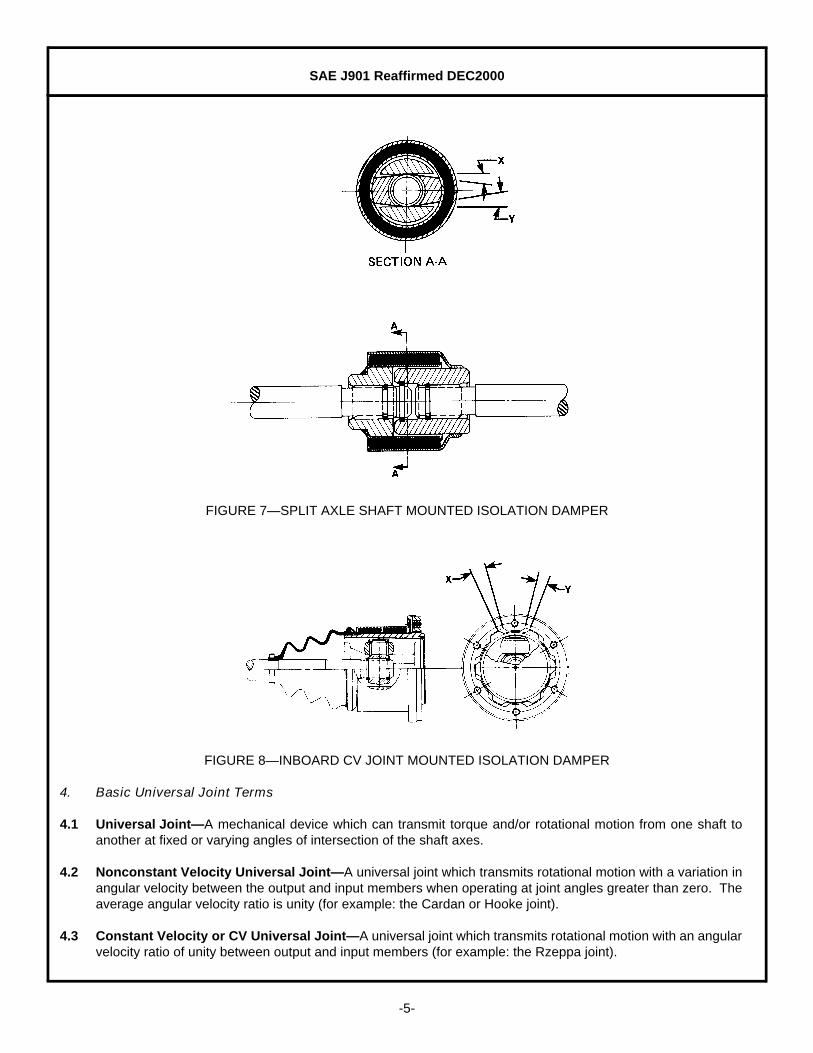
3.3 Halfshaft—A driveshaft, normally one of two, that connects the chassis mounted final drive unit to theindependently sprung driven wheel of a vehicle (see Figures 2 and 3).
3.4 Driveshaft Length, Center-to-Center—The distance between the outermost universal joint centers on adriveshaft. On driveshafts with fixed centers, it is the nominal dimension, while on driveshafts with variablelength centers, it is the compressed and extended lengths (see Figure 1).
3.5 Slip—The permissible length of axial travel.
3.6 Stroke or Plunge Distance—The relative axial displacement of an end motion or stroking universal joint'sdriving and driven members.
SAE J901 Reaffirmed DEC2000
-2-
FIGURE 1—BASIC DRIVESHAFT CONSTRUCTIONS
FIGURE 2—TYPICAL FRONT-WHEEL-DRIVE HALFSHAFT WITH ALTERNATE INBOARD END MOTION UNIVERSAL JOINTS

SAE J901 Reaffirmed DEC2000
-3-
FIGURE 3—TYPICAL REAR-WHEEL-DRIVE HALFSHAFT WITH END MOTION UNIVERSAL JOINTS (CROSS GROOVE TYPE SHOWN)
3.7 Phase Angle—The relative rotational position of the universal joint yokes on a driveshaft or driveline (seeFigure 1).
3.8 Critical Speed—The speed at which the rotational speed coincides with the transverse natural vibrationfrequency of the driveshaft.
3.9 Balancing—A procedure by which the mass distribution of a rotating body is measured and, if necessary,altered in order to ensure that it is within specified limits.
3.10 Mass Damper—A concentrated mass generally clamped on a halfshaft midway between the universal joints.It is used to reduce the natural bending frequency of the halfshaft below a disturbing frequency (see Figure 4).
FIGURE 4—AXLE SHAFT MOUNTED MASS DAMPER
3.11 Torsional Damper or Vibration Absorber—A torsionally tuned mechanical device which generally consistsof an inertia ring attached to a drivetrain component by means of an elastomeric inner ring. It is tuned to aspecific disturbing frequency (see Figures 5 and 6).
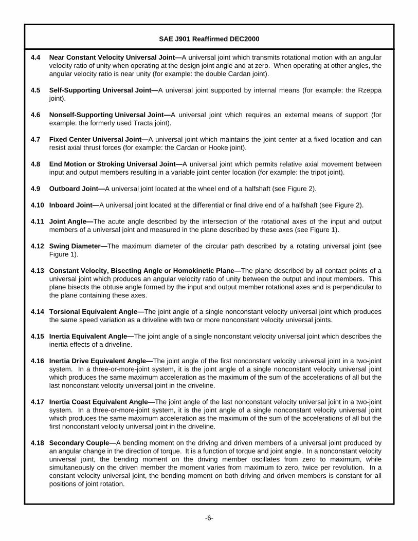
3.12 Isolation Damper—A mechanical torque transmitting device incorporated in a halfshaft which functions as adisturbance isolator. It eliminates, by means of an elastomeric inner ring or rings, undesirable throttle or shiftinduced noises or disturbances resulting from transaxle gear lash. This device is normally installed only onone halfshaft in a vehicle (see Figures 7 and 8).

SAE J901 Reaffirmed DEC2000
-4-
FIGURE 5—TYPICAL TWO-JOINT OUTBOARD SLIP DRIVESHAFT
FIGURE 6—AXLE SHAFT MOUNTED TORSIONAL DAMPER
SAE J901 Reaffirmed DEC2000
-5-
FIGURE 7—SPLIT AXLE SHAFT MOUNTED ISOLATION DAMPER
FIGURE 8—INBOARD CV JOINT MOUNTED ISOLATION DAMPER
4. Basic Universal Joint Terms
4.1 Universal Joint—A mechanical device which can transmit torque and/or rotational motion from one shaft toanother at fixed or varying angles of intersection of the shaft axes.
4.2 Nonconstant Velocity Universal Joint—A universal joint which transmits rotational motion with a variation inangular velocity between the output and input members when operating at joint angles greater than zero. Theaverage angular velocity ratio is unity (for example: the Cardan or Hooke joint).
4.3 Constant Velocity or CV Universal Joint—A universal joint which transmits rotational motion with an angularvelocity ratio of unity between output and input members (for example: the Rzeppa joint).
SAE J901 Reaffirmed DEC2000
-6-
4.4 Near Constant Velocity Universal Joint—A universal joint which transmits rotational motion with an angularvelocity ratio of unity when operating at the design joint angle and at zero. When operating at other angles, theangular velocity ratio is near unity (for example: the double Cardan joint).
4.5 Self-Supporting Universal Joint—A universal joint supported by internal means (for example: the Rzeppajoint).
4.6 Nonself-Supporting Universal Joint—A universal joint which requires an external means of support (forexample: the formerly used Tracta joint).
4.7 Fixed Center Universal Joint—A universal joint which maintains the joint center at a fixed location and canresist axial thrust forces (for example: the Cardan or Hooke joint).
4.8 End Motion or Stroking Universal Joint—A universal joint which permits relative axial movement betweeninput and output members resulting in a variable joint center location (for example: the tripot joint).
4.9 Outboard Joint—A universal joint located at the wheel end of a halfshaft (see Figure 2).
4.10 Inboard Joint—A universal joint located at the differential or final drive end of a halfshaft (see Figure 2).
4.11 Joint Angle—The acute angle described by the intersection of the rotational axes of the input and outputmembers of a universal joint and measured in the plane described by these axes (see Figure 1).
4.12 Swing Diameter—The maximum diameter of the circular path described by a rotating universal joint (seeFigure 1).
4.13 Constant Velocity, Bisecting Angle or Homokinetic Plane—The plane described by all contact points of auniversal joint which produces an angular velocity ratio of unity between the output and input members. Thisplane bisects the obtuse angle formed by the input and output member rotational axes and is perpendicular tothe plane containing these axes.
4.14 Torsional Equivalent Angle—The joint angle of a single nonconstant velocity universal joint which producesthe same speed variation as a driveline with two or more nonconstant velocity universal joints.
4.15 Inertia Equivalent Angle—The joint angle of a single nonconstant velocity universal joint which describes theinertia effects of a driveline.
4.16 Inertia Drive Equivalent Angle—The joint angle of the first nonconstant velocity universal joint in a two-jointsystem. In a three-or-more-joint system, it is the joint angle of a single nonconstant velocity universal jointwhich produces the same maximum acceleration as the maximum of the sum of the accelerations of all but thelast nonconstant velocity universal joint in the driveline.
4.17 Inertia Coast Equivalent Angle—The joint angle of the last nonconstant velocity universal joint in a two-jointsystem. In a three-or-more-joint system, it is the joint angle of a single nonconstant velocity universal jointwhich produces the same maximum acceleration as the maximum of the sum of the accelerations of all but thefirst nonconstant velocity universal joint in the driveline.
4.18 Secondary Couple—A bending moment on the driving and driven members of a universal joint produced byan angular change in the direction of torque. It is a function of torque and joint angle. In a nonconstant velocityuniversal joint, the bending moment on the driving member oscillates from zero to maximum, whilesimultaneously on the driven member the moment varies from maximum to zero, twice per revolution. In aconstant velocity universal joint, the bending moment on both driving and driven members is constant for allpositions of joint rotation.

SAE J901 Reaffirmed DEC2000
-7-
4.19 Bearing Factor—A size characteristic for comparing the various size Cardan and double Cardan typeuniversal joints relative to bearing capacity. It is the product of the projected needle roller bearing area on thecross trunnion times the torque radius (see Figure 9).
FIGURE 9—NEEDLE ROLLER BEARING AND CROSS CONFIGURATION
5. Universal Joints
5.1 Nonconstant Velocity Types
5.1.1 CARDAN OR HOOKE UNIVERSAL JOINT—A nonconstant velocity universal joint which consists of two yokesdrivably connected by a cross through four bearings (see Figure 10).
FIGURE 10—CARDAN UNIVERSAL JOINT

SAE J901 Reaffirmed DEC2000
-8-
5.1.1.1 Yoke—The basic torque and/or motion input and output member with drivable means of attachment.
5.1.1.2 Slip Yoke—A yoke which accommodates axial movement (see Figures 11 and 5).
FIGURE 11—SLIP YOKE
5.1.1.3 Tube or Weld Yoke—A yoke with a piloting hub for attachment to a tube or other shaft member (seeFigures 12 and 5).
FIGURE 12—TUBE OR WELD YOKE
SAE J901 Reaffirmed DEC2000
-9-
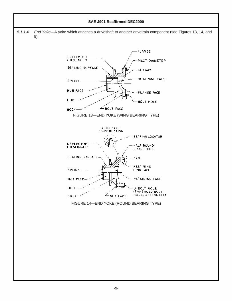
5.1.1.4 End Yoke—A yoke which attaches a driveshaft to another drivetrain component (see Figures 13, 14, and5).
FIGURE 13—END YOKE (WING BEARING TYPE)
FIGURE 14—END YOKE (ROUND BEARING TYPE)

SAE J901 Reaffirmed DEC2000
-10-
5.1.1.5 Flange Yoke—A yoke which attaches a driveshaft to a companion flange (see Figures 15 and 5).
FIGURE 15—FLANGE YOKE
5.1.1.6 Companion Flange—A flange member that fixedly attaches a driveshaft to another drivetrain component(see Figures 16 and 5).
FIGURE 16—COMPANION FLANGE
5.1.1.7 Ear—One of two projecting parts of a yoke symmetrically located with respect to the rotational axis (seeFigure 11).
5.1.1.8 Hub—The central part of a member used for attachment to another member (see Figure 11).
5.1.1.9 Bearing Cross Hole—A through hole in each ear of a yoke used to locate a round bearing (see Figure 11).
5.1.1.10 Half Round Cross Hole—A semicircular hole located on the end of each ear of some end yoke designs(see Figures 14 and 5).
5.1.1.11 Bearing Locator—A projection in a half round cross hole, of some end yoke designs, used to locate around bearing with respect to the yoke centerline (see Figure 14).

SAE J901 Reaffirmed DEC2000
-11-
5.1.1.12 Retaining Ring Groove—A groove used to locate a retaining ring (see Figure 11).
5.1.1.13 Retaining Ring—A removable member used as a shoulder to retain and position a round bearing in a hole(see Figures 10, 17, and 5).
FIGURE 17—BEARING AND RETAINER TYPES
5.1.1.14 U-Bolt—A clamping type bolt with two threaded parallel legs used to retain a round bearing in some endyoke designs (see Figures 17 and 5).
5.1.1.15 Round Bearing—Consists of a round bearing cup with needle rollers generally held in place by a needleroller retainer or a bearing seal (see Figures 17 and 5).
5.1.1.16 Round Bearing Cup—A cup-shaped member used as the bearing bore of a round bearing and forpositioning the thrust end of a cross trunnion (see Figures 10 and 18).
5.1.1.17 Needle Roller—One of the rolling elements of a bearing (see Figures 10 and 18).
5.1.1.18 Needle Roller Retainer—A member used to retain needle rollers in a bearing.
5.1.1.19 Bearing Seal—A flexible member which prevents the escape of lubricant from or entry of foreign matterinto a bearing (see Figures 10, 19, and 18).
5.1.1.20 Deflector or Slinger—A protective member whose function is to exclude foreign objects from the bearingseal (see Figures 13 and 18).
5.1.1.21 Seal Retainer—A member used to hold a bearing seal in position on the bearing (see Figure 18).
5.1.1.22 Wing Bearing—Consists of a wing bearing cup with needle rollers generally held in place by a needle rollerretainer or a bearing seal (see Figures 17 and 5).

SAE J901 Reaffirmed DEC2000
-12-
FIGURE 18—DOUBLE CARDAN UNIVERSAL JOINT

SAE J901 Reaffirmed DEC2000
-13-
FIGURE 19—BEARING SEAL TYPES
5.1.1.23 Wing Bearing Cup—A member with a key and projecting wings used as the bearing bore of a wing bearingand for positioning the thrust end of a cross trunnion. The low wing bearing type cup has thin flangedwings for attachment. The high wing or block bearing type cup has thick flanged wings for attachment.The delta wing bearing type cup has delta-shaped flanged wings for attachment (see Figure 17).
5.1.1.24 Round Bearing (Retainer Plate Type)—Consists of a round bearing with a generally integral retainer platefor retaining and positioning the bearing in a yoke (see Figure 17).
5.1.1.25 Strap—A narrow plate type member used to retain a round bearing in some end yoke designs (see Figures17 and 5).
5.1.1.26 Retaining Ring Face—A surface used for positioning a round bearing with a retaining ring (see Figure 11).
5.1.1.27 Thrust Face—The closed end of a bearing used as a thrust surface.
5.1.1.28 Cross—The intermediate drive member which has four equally spaced trunnions in the same plane (seeFigures 20 and 5).

SAE J901 Reaffirmed DEC2000
-14-
FIGURE 20—CROSS
5.1.1.29 Trunnion—Any one of the four projecting journals of a cross (see Figure 20).
5.1.1.30 Trunnion Diameter—The diameter of a projecting journal of a cross (see Figure 20).
5.1.1.31 Thrust End—The end of the cross trunnion used as a thrust surface (see Figure 20).
5.2 Constant Velocity Types
5.2.1 DOUBLE CARDAN UNIVERSAL JOINT—A near constant velocity universal joint which consists of two Cardanuniversal joints whose crosses are connected by a coupling yoke with internal supporting and centeringmeans and has intersecting shaft axes. At the design joint angle and at zero, the instantaneous angularvelocity ratio is unity, while at joint angles it is near unity (see Figure 18).
5.2.1.1 Coupling Yoke—A double yoke which connects the two halves of a double Cardan universal joint (seeFigure 18).
5.2.1.2 Socket Yoke—A yoke incorporating a socket (see Figure 18).
5.2.1.3 Socket—A separate bearing member or integral cavity in a yoke used to pivotally locate and support theball of a ball and socket type centering device (see Figure 18).
5.2.1.4 Ball and Socket Type Centering Device—A mechanism which functions as a self-aligning bearing andprovides internal supporting and centering means for a double Cardan type universal joint. The two basictypes of ball and socket designs are the centering ball and stud and the ball stud and seat constructions(see Figure 18).

SAE J901 Reaffirmed DEC2000
-15-
5.2.1.5 Centering Stud Yoke—A yoke incorporating a centering stud (see Figure 18).
5.2.1.6 Centering Stud—A part of a yoke used to support a centering ball (see Figure 18).
5.2.1.7 Centering Ball—A partly spherically shaped member which pivots and provides supporting and centeringmeans (see Figure 18).
5.2.1.8 Ball Stud Yoke—A yoke incorporating a ball stud (see Figure 18).
5.2.1.9 Ball Stud—A partly spherically shaped part of a yoke which pivots and provides supporting and centeringmeans (see Figure 18).
5.2.1.10 Ball Seat—A full or segmented ring-like angular contact bearing member located in a socket whichsupports and centers the ball stud (see Figure 18).
5.2.2 TRIPOT OR TRIPOD UNIVERSAL JOINT (END MOTION TYPE)—A constant velocity universal joint, radially self-supported and permitting axial movement, which consists of a housing drivably connected to a shaft throughthree equally spaced trunnion mounted balls (see Figure 21).
FIGURE 21—TRIPOT OR TRIPOD UNIVERSAL JOINT (END MOTION TYPE)
5.2.2.1 Housing—A member with three equally spaced, partly cylindrical axial ball bores on the cylindrical innerclearance surface and with drivable means of attachment. In the tulip type housing, these ball bores haveopen circular segments on the periphery, as well as on the inner clearance surface Figures 21, 22, and 23.
5.2.2.2 Spider—A member with three equally spaced trunnions in the same plane and with internally splineddrivable means of attachment (see Figures 21 and 22).
5.2.2.3 Ball—A partly spherically shaped member which pivots and transmits torque from the housing to the shaftthrough the spider and permits axial movement. Generally, needle rollers are used between the ball andthe spider (see Figures 21 and 22).

SAE J901 Reaffirmed DEC2000
-16-
FIGURE 22—TRIPOT OR TRIPOD UNIVERSAL JOINT (END MOTION TYPE)
FIGURE 23—TYPICAL TRIPOT OR TRIPOD JOINT HOUSING CONSTRUCTIONS
5.2.2.4 Boot Seal—A flexible member that prevents the escape of lubricant from or entry of foreign matter into theuniversal joint (see Figures 21 and 22).
5.2.2.5 Band—A ring-like member used to hold the boot seal in position on the universal joint or shaft (see Figure12).
5.2.2.6 Clamp—An adjustable band used to hold the boot seal in position on the universal joint or shaft (seeFigures 21 and 22).
5.2.2.7 Needle Roller Retainer—A member that radially positions and retains the needle rollers on the spidertrunnion (see Figures 21 and 22).
5.2.2.8 Retaining Ring—A removable member used as a shoulder for retaining and positioning universal jointcomponents in an assembly (see Figures 21 and 22).
5.2.3 TRIPOT OR TRIPOD UNIVERSAL JOINT (FIXED CENTER TYPE)—A self-supported constant velocity universal jointwhich consists of a housing drivably connected to a forked shaft through three equally spaced trunnionmounted balls and retained as an assembly by a retaining clip. The joint center is maintained in asubstantially fixed axial location by means of a spring-loaded centering device (see Figure 24).
SAE J901 Reaffirmed DEC2000
-17-
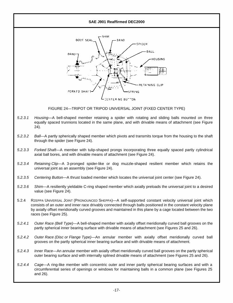
FIGURE 24—TRIPOT OR TRIPOD UNIVERSAL JOINT (FIXED CENTER TYPE)
5.2.3.1 Housing—A bell-shaped member retaining a spider with rotating and sliding balls mounted on threeequally spaced trunnions located in the same plane, and with drivable means of attachment (see Figure24).
5.2.3.2 Ball—A partly spherically shaped member which pivots and transmits torque from the housing to the shaftthrough the spider (see Figure 24).
5.2.3.3 Forked Shaft—A member with tulip-shaped prongs incorporating three equally spaced partly cylindricalaxial ball bores, and with drivable means of attachment (see Figure 24).
5.2.3.4 Retaining Clip—A 3-pronged spider-like or dog muzzle-shaped resilient member which retains theuniversal joint as an assembly (see Figure 24).
5.2.3.5 Centering Button—A thrust loaded member which locates the universal joint center (see Figure 24).
5.2.3.6 Shim—A resiliently yieldable C-ring shaped member which axially preloads the universal joint to a desiredvalue (see Figure 24).
5.2.4 RZEPPA UNIVERSAL JOINT (PRONOUNCED SHEPPA)—A self-supported constant velocity universal joint whichconsists of an outer and inner race drivably connected through balls positioned in the constant velocity planeby axially offset meridionally curved grooves and maintained in this plane by a cage located between the tworaces (see Figure 25).
5.2.4.1 Outer Race (Bell Type)—A bell-shaped member with axially offset meridionally curved ball grooves on thepartly spherical inner bearing surface with drivable means of attachment (see Figures 25 and 26).
5.2.4.2 Outer Race (Disc or Flange Type)—An annular member with axially offset meridionally curved ballgrooves on the partly spherical inner bearing surface and with drivable means of attachment.
5.2.4.3 Inner Race—An annular member with axially offset meridionally curved ball grooves on the partly sphericalouter bearing surface and with internally splined drivable means of attachment (see Figures 25 and 26).
5.2.4.4 Cage—A ring-like member with concentric outer and inner partly spherical bearing surfaces and with acircumferential series of openings or windows for maintaining balls in a common plane (see Figures 25and 26).
SAE J901 Reaffirmed DEC2000
-18-
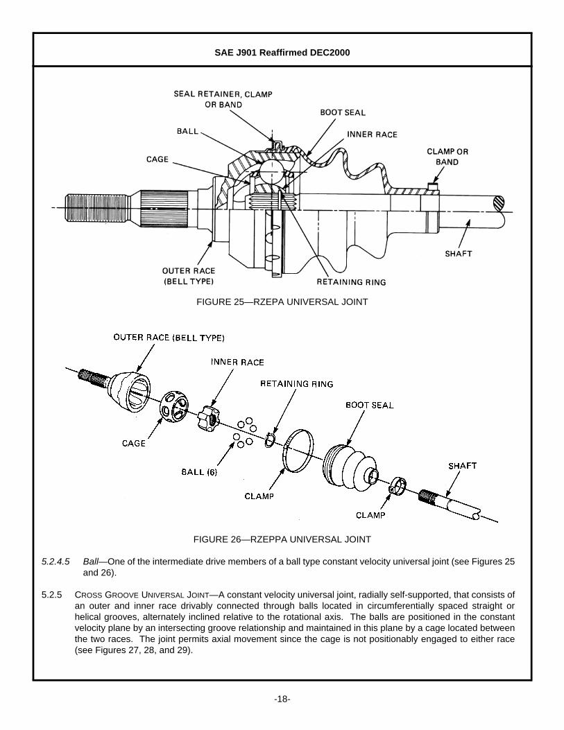
FIGURE 25—RZEPA UNIVERSAL JOINT
FIGURE 26—RZEPPA UNIVERSAL JOINT
5.2.4.5 Ball—One of the intermediate drive members of a ball type constant velocity universal joint (see Figures 25and 26).
5.2.5 CROSS GROOVE UNIVERSAL JOINT—A constant velocity universal joint, radially self-supported, that consists ofan outer and inner race drivably connected through balls located in circumferentially spaced straight orhelical grooves, alternately inclined relative to the rotational axis. The balls are positioned in the constantvelocity plane by an intersecting groove relationship and maintained in this plane by a cage located betweenthe two races. The joint permits axial movement since the cage is not positionably engaged to either race(see Figures 27, 28, and 29).

SAE J901 Reaffirmed DEC2000
-19-
FIGURE 27—CROSS GROOVE UNIVERSAL JOINT
FIGURE 28—DEVELOPMENT VIEW OF CROSS GROOVE JOINT ILLUSTRATING RELATIONSHIP OF OUTER AND INNER RACE BALL GROOVES AND POSITIONING OF BALLS
SAE J901 Reaffirmed DEC2000
-20-
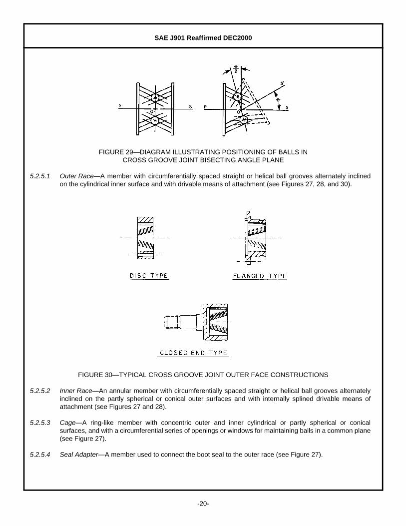
FIGURE 29—DIAGRAM ILLUSTRATING POSITIONING OF BALLS IN CROSS GROOVE JOINT BISECTING ANGLE PLANE
5.2.5.1 Outer Race—A member with circumferentially spaced straight or helical ball grooves alternately inclinedon the cylindrical inner surface and with drivable means of attachment (see Figures 27, 28, and 30).
FIGURE 30—TYPICAL CROSS GROOVE JOINT OUTER FACE CONSTRUCTIONS
5.2.5.2 Inner Race—An annular member with circumferentially spaced straight or helical ball grooves alternatelyinclined on the partly spherical or conical outer surfaces and with internally splined drivable means ofattachment (see Figures 27 and 28).
5.2.5.3 Cage—A ring-like member with concentric outer and inner cylindrical or partly spherical or conicalsurfaces, and with a circumferential series of openings or windows for maintaining balls in a common plane(see Figure 27).
5.2.5.4 Seal Adapter—A member used to connect the boot seal to the outer race (see Figure 27).

SAE J901 Reaffirmed DEC2000
-21-
5.2.6 DOUBLE OFFSET OR DO UNIVERSAL JOINT (END MOTION TYPE)—A constant velocity universal joint, radiallyself-supported that consists of an outer and inner race drivably connected through the balls located in axiallystraight grooves. The balls are positioned and maintained in the constant velocity plane by a cage withaxially offset spherical surfaces located between the two races. The joint permits axial movement since thecage is positionably engaged only by the inner race (see Figures 31 and 32).
FIGURE 31—DOUBLE OFFSET OR DO UNIVERSAL JOINT (END MOTION TYPE)
FIGURE 32—DIAGRAM ILLUSTRATING OFFSET RELATIONSHIP OF DOUBLE OFFSET CAGE SPHERICAL SURFACES
SAE J901 Reaffirmed DEC2000
-22-
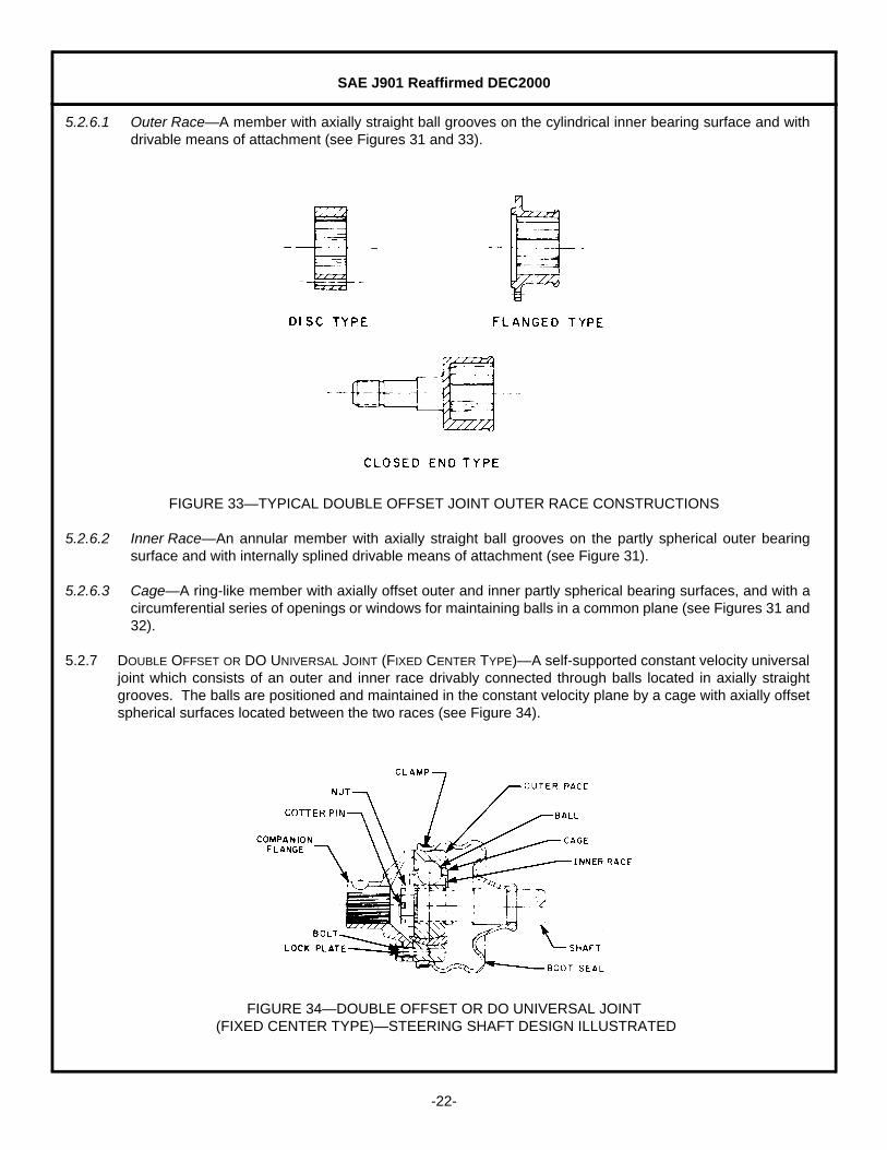
5.2.6.1 Outer Race—A member with axially straight ball grooves on the cylindrical inner bearing surface and withdrivable means of attachment (see Figures 31 and 33).
FIGURE 33—TYPICAL DOUBLE OFFSET JOINT OUTER RACE CONSTRUCTIONS
5.2.6.2 Inner Race—An annular member with axially straight ball grooves on the partly spherical outer bearingsurface and with internally splined drivable means of attachment (see Figure 31).
5.2.6.3 Cage—A ring-like member with axially offset outer and inner partly spherical bearing surfaces, and with acircumferential series of openings or windows for maintaining balls in a common plane (see Figures 31 and32).
5.2.7 DOUBLE OFFSET OR DO UNIVERSAL JOINT (FIXED CENTER TYPE)—A self-supported constant velocity universaljoint which consists of an outer and inner race drivably connected through balls located in axially straightgrooves. The balls are positioned and maintained in the constant velocity plane by a cage with axially offsetspherical surfaces located between the two races (see Figure 34).
FIGURE 34—DOUBLE OFFSET OR DO UNIVERSAL JOINT (FIXED CENTER TYPE)—STEERING SHAFT DESIGN ILLUSTRATED

SAE J901 Reaffirmed DEC2000
-23-
5.2.7.1 Outer Race—An annular member with axially straight ball grooves on the partly spherical inner bearingsurface and with drivable means of attachment (see Figure 34).
6. Driveshaft Types
6.1 Two-Joint Outboard Slip Driveshaft—A driveshaft or part of a driveline having a universal joint at each end.Axial movement is provided outboard of joint centers (see Figure 1).
6.2 Two-Joint Inboard Slip Driveshaft—A driveshaft or part of a driveline having a universal joint at each end.Axial movement is provided inboard of joint centers (see Figure 1).
6.3 Single Joint Coupling Shaft—The coupling member or members of a multiple joint driveline consisting of oneuniversal joint, tube, shaft support, and slip spline or fixed spline shaft (see Figure 1).
An exploded view of a typical two-joint outboard slip driveshaft with alternate component constructions isillustrated in Figure 5. An exploded view of a typical two-piece heavy-duty truck driveline is shown in Figure35, and Figure 36 illustrates a typical short coupled driveshaft.
FIGURE 35—TYPICAL TWO-PIECE HEAVY-DUTY TRUCK DRIVELINE
SAE J901 Reaffirmed DEC2000
-24-
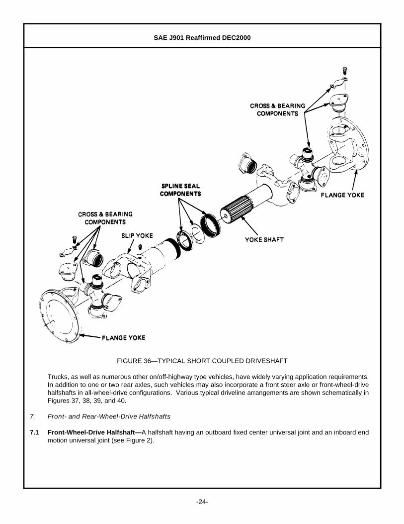
FIGURE 36—TYPICAL SHORT COUPLED DRIVESHAFT
Trucks, as well as numerous other on/off-highway type vehicles, have widely varying application requirements.In addition to one or two rear axles, such vehicles may also incorporate a front steer axle or front-wheel-drivehalfshafts in all-wheel-drive configurations. Various typical driveline arrangements are shown schematically inFigures 37, 38, 39, and 40.
7. Front- and Rear-Wheel-Drive Halfshafts
7.1 Front-Wheel-Drive Halfshaft—A halfshaft having an outboard fixed center universal joint and an inboard endmotion universal joint (see Figure 2).

SAE J901 Reaffirmed DEC2000
-25-
FIGURE 37—TYPICAL 4 X 2 AND 6 X 2 TRUCK DRIVELINE ARRANGEMENTS
FIGURE 38—TYPICAL 4 X 4 TRUCK DRIVELINE ARRANGEMENTS

SAE J901 Reaffirmed DEC2000
-26-
FIGURE 39—TYPICAL 6 X 4 TRUCK DRIVELINE ARRANGEMENTS
FIGURE 40—TYPICAL 6 X 6 TRUCK DRIVELINE ARRANGEMENTS
7.2 Rear-Wheel-Drive Halfshaft—A halfshaft having two universal joints which may be both either fixed center orend motion universal joints, or one may be a fixed center and the other may be an end motion universal joint(see Figure 3).
Figure 2 illustrates a typical front-wheel-drive halfshaft with alternate inboard end motion universal joints. Atypical rear-wheel-drive halfshaft with two end motion universal joints is shown in Figure 3.
8. Halfshaft Tuning Devices—A tuning device may have to be incorporated in a front-wheel-drive halfshaftdepending upon the requirements of the specific vehicle application. Figure 41 shows a solid and tubular axleshaft, while Figure 4 illustrates an axle shaft mounted mass damper. With these three axle shaft constructions,it is possible to achieve a desired shaft natural bending frequency by altering their transverse bendingstiffness. Figure 6 shows an axle shaft mounted torsional damper, which consists of an inertia ring attached toan axle shaft by means of an elastomeric inner ring. In this tuning device, the inertia ring can oscillatetorsionally and is tuned to a specific disturbing frequency.
FIGURE 41—SOLID AND TUBULAR AXLE SHAFTS
SAE J901 Reaffirmed DEC2000
-27-
In addition, a halfshaft tuning device can function essentially as a disturbance isolator. Figure 7 illustrates asplit axle shaft mounted isolation damper, while Figure 8 shows an inboard CV joint mounted isolation damper.Both of these devices can transmit relatively low torsional loads through an elastomeric ring or rings. Whenthe angular travel limitation stops in forward or reverse rotational directions are reached, the transmission ofhigher torque loads is by means of a solid connection. These devices eliminate disturbances during throttletip-in and tip-out as well as forward and reverse shift clunk or thud due to transaxle gear lash.
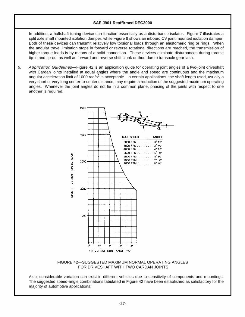
9. Application Guidelines—Figure 42 is an application guide for operating joint angles of a two-joint driveshaftwith Cardan joints installed at equal angles where the angle and speed are continuous and the maximumangular acceleration limit of 1000 rad/s2 is acceptable. In certain applications, the shaft length used, usually avery short or very long center-to-center distance, may require a reduction of the suggested maximum operatingangles. Whenever the joint angles do not lie in a common plane, phasing of the joints with respect to oneanother is required.
FIGURE 42—SUGGESTED MAXIMUM NORMAL OPERATING ANGLES FOR DRIVESHAFT WITH TWO CARDAN JOINTS
Also, considerable variation can exist in different vehicles due to sensitivity of components and mountings.The suggested speed-angle combinations tabulated in Figure 42 have been established as satisfactory for themajority of automotive applications.
SAE J901 Reaffirmed DEC2000
-28-
The Cardan joint can be rated in a manner which establishes a common size characteristic for comparison withother size Cardan joints. Figure 9 shows a cross-sectional view of the cross trunnion and bearing configurationof a joint. The bearing is acted upon by the torque couple force F which is assumed to be concentrated at thecentroid of the projected bearing area on the cross trunnion, formed by the cross trunnion diameter D and theeffective length L of the needle rollers. This couple force is at a distance R from the center of the cross and iscalled the torque radius.
The size characteristic of the joint can be expressed by a term called the “bearing factor,” BF, which isdetermined in Equation 1:
(Eq. 1)
where:
D = Trunnion diameter, inL = Effective needle roller length on cross trunnion, inR = Torque Radius, in
Therefore, the “bearing factor” is simply the product of the projected bearing area on the cross trunnion timesthe torque radius, and serves as an “index” by providing a simple means for comparing various size joints withregard to relative bearing capacity.
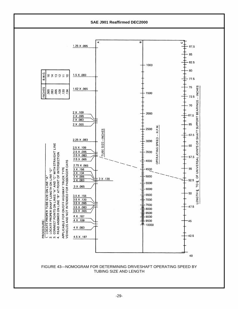
The operating speed of driveshafts can be found by means of a nomogram shown in Figure 43. In thisnomogram, the operating speed can be determined by tubing size and length for driveshaft quality weldedsteel tubing. It is applicable for on/off-highway truck type vehicles and is not intended for passenger cars.
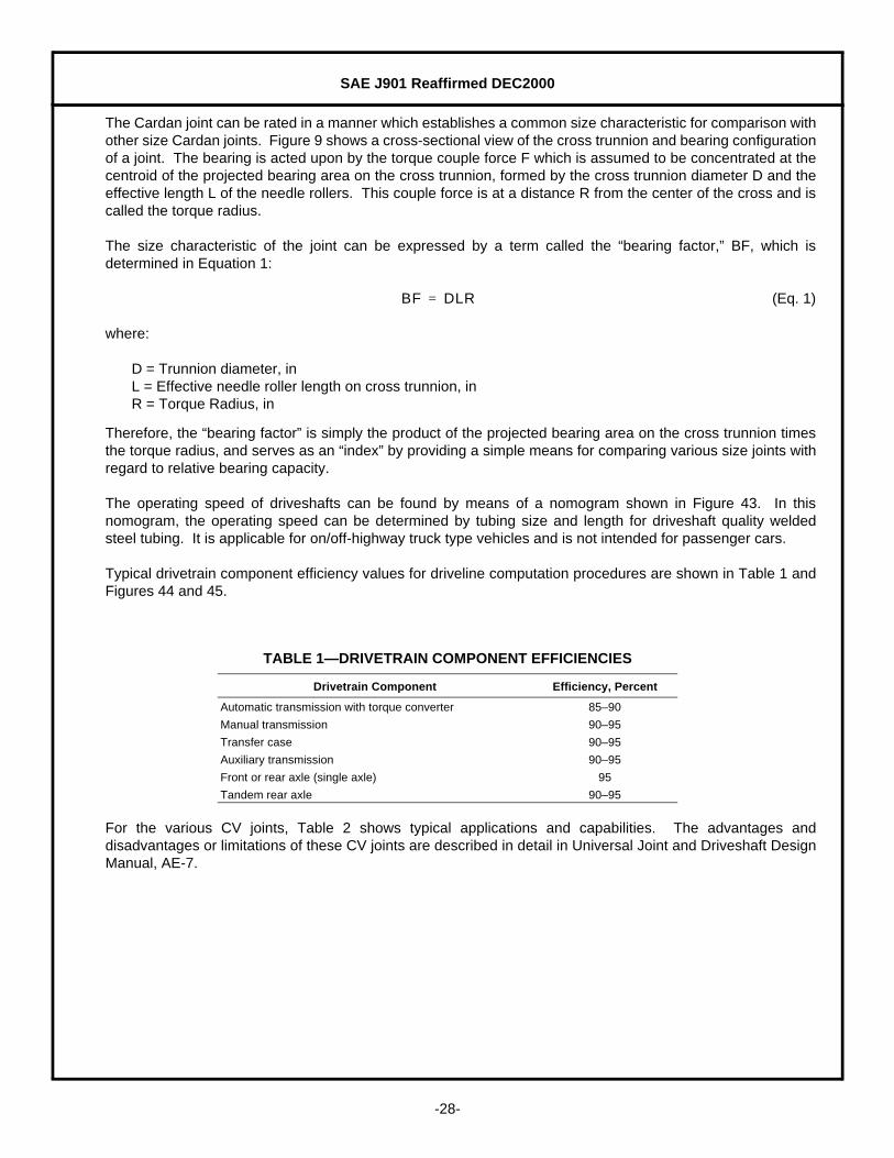
Typical drivetrain component efficiency values for driveline computation procedures are shown in Table 1 andFigures 44 and 45.
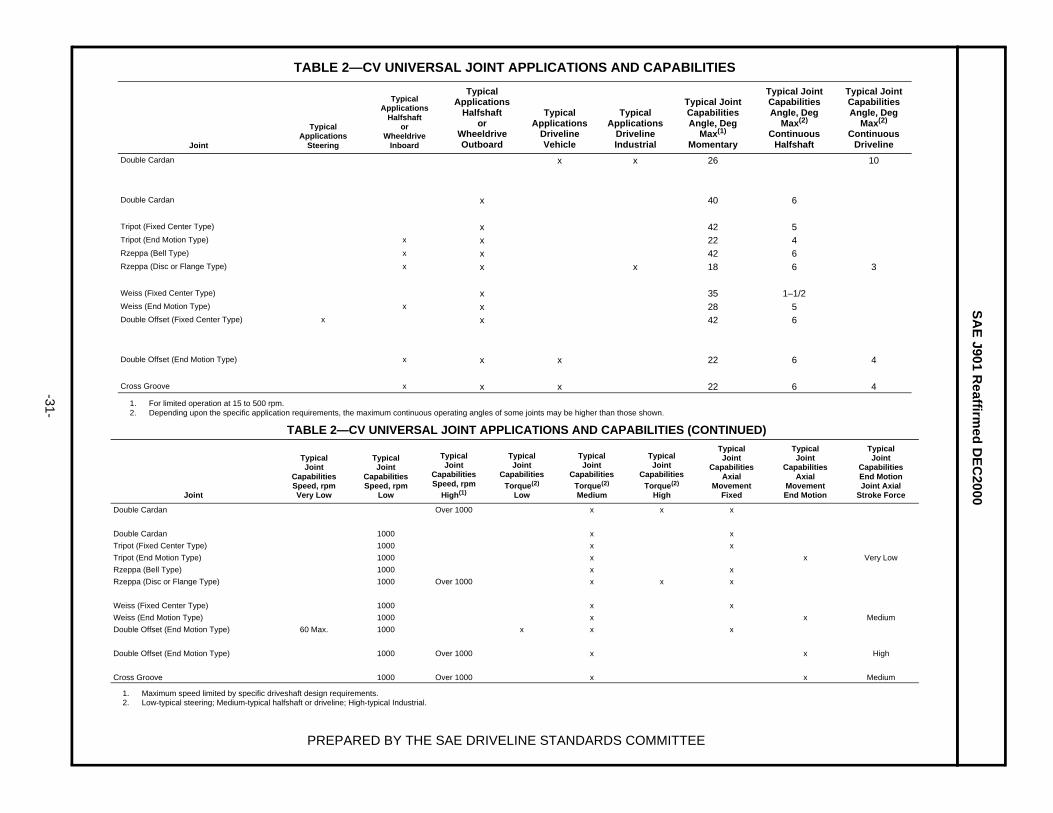
For the various CV joints, Table 2 shows typical applications and capabilities. The advantages anddisadvantages or limitations of these CV joints are described in detail in Universal Joint and Driveshaft DesignManual, AE-7.
TABLE 1—DRIVETRAIN COMPONENT EFFICIENCIES
Drivetrain Component Efficiency, Percent
Automatic transmission with torque converter 85–90
Manual transmission 90–95
Transfer case 90–95
Auxiliary transmission 90–95
Front or rear axle (single axle) 95
Tandem rear axle 90–95
BF DLR=
SAE J901 Reaffirmed DEC2000
-29-
FIGURE 43—NOMOGRAM FOR DETERMINING DRIVESHAFT OPERATING SPEED BYTUBING SIZE AND LENGTH

SAE J901 Reaffirmed DEC2000
-30-
FIGURE 44—EFFICIENCY OF DRIVESHAFT WITH TWO CARDAN JOINTS
FIGURE 45—EFFICIENCY OF BALL TYPE CV JOINTS
SA
E J901 R
eaffirmed
DE
C2000
-31-
TABLE 2—CV UNIVERSAL JOINT APPLICATIONS AND CAPABILITIES (CONTINUED)
PREPARED BY THE SAE DRIVELINE STANDARDS COMMITTEE
TABLE 2—CV UNIVERSAL JOINT APPLICATIONS AND CAPABILITIES
Joint
TypicalApplications
Steering
TypicalApplications
Halfshaftor
WheeldriveInboard
TypicalApplications
Halfshaftor
WheeldriveOutboard
TypicalApplications
DrivelineVehicle
TypicalApplications
DrivelineIndustrial
Typical JointCapabilitiesAngle, Deg
Max(1)
Momentary
1. For limited operation at 15 to 500 rpm.
Typical JointCapabilitiesAngle, Deg
Max(2)
ContinuousHalfshaft
2. Depending upon the specific application requirements, the maximum continuous operating angles of some joints may be higher than those shown.
Typical JointCapabilitiesAngle, Deg
Max(2)
ContinuousDriveline
Double Cardan x x 26 10
Double Cardan x 40 6
Tripot (Fixed Center Type) x 42 5Tripot (End Motion Type) x x 22 4Rzeppa (Bell Type) x x 42 6Rzeppa (Disc or Flange Type) x x x 18 6 3
Weiss (Fixed Center Type) x 35 1–1/2Weiss (End Motion Type) x x 28 5Double Offset (Fixed Center Type) x x 42 6
Double Offset (End Motion Type) x x x 22 6 4
Cross Groove x x x 22 6 4
Joint
TypicalJoint
CapabilitiesSpeed, rpmVery Low
TypicalJoint
CapabilitiesSpeed, rpm
Low
TypicalJoint
CapabilitiesSpeed, rpm
High(1)
1. Maximum speed limited by specific driveshaft design requirements.
TypicalJoint
CapabilitiesTorque(2)
Low
2. Low-typical steering; Medium-typical halfshaft or driveline; High-typical Industrial.
TypicalJoint
CapabilitiesTorque(2)
Medium
TypicalJoint
CapabilitiesTorque(2)
High
TypicalJoint
CapabilitiesAxial
MovementFixed
TypicalJoint
CapabilitiesAxial
MovementEnd Motion
TypicalJoint
CapabilitiesEnd MotionJoint Axial
Stroke Force
Double Cardan Over 1000 x x x
Double Cardan 1000 x x
Tripot (Fixed Center Type) 1000 x x
Tripot (End Motion Type) 1000 x x Very Low
Rzeppa (Bell Type) 1000 x x
Rzeppa (Disc or Flange Type) 1000 Over 1000 x x x
Weiss (Fixed Center Type) 1000 x x
Weiss (End Motion Type) 1000 x x Medium
Double Offset (End Motion Type) 60 Max. 1000 x x x
Double Offset (End Motion Type) 1000 Over 1000 x x High
Cross Groove 1000 Over 1000 x x Medium

SAE J901 Reaffirmed DEC2000
Rationale—Not applicable.
Relationship of SAE Standard to ISO Standard—Not applicable.
Application—The following definitions and illustrations are intended to establish common nomenclature andterminology for universal joints and driveshafts used in various driveline applications. In addition, usefulguidelines are included for the application of universal joints and driveshafts. For more specific details,see Universal Joint and Driveshaft Design Manual, AE-7.
Reference Section
AE-7 Universal Joint and Driveshaft Design Manual
Developed by the SAE Driveline Standards Committee