surgical technique - the royal children's hospital : the royal … · 2013-11-04 · small...
TRANSCRIPT

Original Instruments and Implants of the Association for the Study of Internal Fixation – AO/ASIF
Small External Fixator
Surgical Technique

Synthes 1
Table of Contents
WarningThis description is not sufficient for immediate application ofthe instrumentation. Instruction by a surgeon experienced inhandling this instrumentation is highly recommended.
Image magnification control
Small External Fixator
Description of System 2
Indications/Contraindications 3
Bridging Surgical Technique 4
Non-bridging Surgical Technique 8
Variant A: Modular Technique with Schanz Screws 9
Variant B: with Kirschner wires 17
References

2
System Description
Small External Fixator
System Description
The small external fixator is a system for simple or complexconfigurations.
It is light in weight, consists of only a few components, andoffers compatibility with mini, medium, and large externalfixators. The clamps with a clip-on, self-holding mechanismallow several types of connection and simplify handling.
A large number of construct variants allows for treatment in allindications.
The main benefits are: independent pin placement, modularprimary and secondary reduction options, good stability,and consideration of (adaptation to) the soft tissue situation.
Synthes 3
Indications/Contraindications
Small External Fixator
Indications
Unstable distal radius fractures– Intra-articular – Extra-articular– Preliminary fixation before open reduction and internal
fixation – Fracture with open and closed soft tissue injury– Multiple trauma (in terms of “damage controlled surgery” –
injury-adapted care)
Other indications
Injuries, fractures, dislocations, burns– Carpal region– Wrist– Forearm– Ankle (possibly in combination with a medium or large
fixator)
Fractures in combination with – Extensive soft tissue injuries – Bone loss– Vascular and/or neural involvement
Fracture dislocation– Carpal bones
Failed closed reduction with casting resulting insecondary dislocation – Radial shortening– Angulation
Contraindications– Patients who for social and physical reasons are not suitable
for an external fixator. – Agitation – Patients in whom screws cannot be inserted due to a bone
or soft tissue disease.

4
Bridging Surgical Technique
Small External Fixator
The assembly of the small external fixator is described hereusing the 3-rod modular technique on the distal radius as theexample.
At the start, perform an initial reduction on the hand with thefractured radius by gentle ligamentotaxis to minimize soft tissueinjuries through internal pressure.
Angle for screw insertion
Implant the Schanz screws into the second metacarpal.
Note: For a better purchase, it is recommended to insert theseat a slight angle. An angle of 40° to 60° between the proximaland distal pin has proven to be best.
Position of the screws
Pay attention to the extensor tendon and the radiodorsal neuro-vascular bundle on the extensor and radiodorsal side. If thescrews are placed too far laterally, they will impede the functionof the thumb. For this reason, an angle between 40° and60° with respect to the horizontal has proven best when viewedfrom the orthograde position.
1
2
Synthes 5
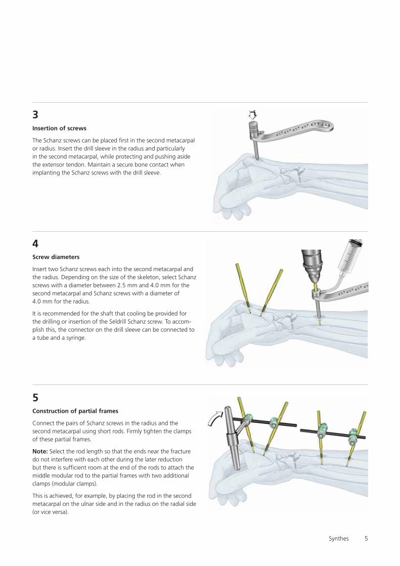
Insertion of screws
The Schanz screws can be placed first in the second metacarpalor radius. Insert the drill sleeve in the radius and particularlyin the second metacarpal, while protecting and pushing asidethe extensor tendon. Maintain a secure bone contact whenimplanting the Schanz screws with the drill sleeve.
3
Screw diameters
Insert two Schanz screws each into the second metacarpal andthe radius. Depending on the size of the skeleton, select Schanzscrews with a diameter between 2.5 mm and 4.0 mm for thesecond metacarpal and Schanz screws with a diameter of4.0 mm for the radius.
It is recommended for the shaft that cooling be provided forthe drilling or insertion of the Seldrill Schanz screw. To accom-plish this, the connector on the drill sleeve can be connected toa tube and a syringe.
4
Construction of partial frames
Connect the pairs of Schanz screws in the radius and thesecond metacarpal using short rods. Firmly tighten the clampsof these partial frames.
Note: Select the rod length so that the ends near the fracturedo not interfere with each other during the later reductionbut there is sufficient room at the end of the rods to attach themiddle modular rod to the partial frames with two additionalclamps (modular clamps).
This is achieved, for example, by placing the rod in the secondmetacarpal on the ulnar side and in the radius on the radial side(or vice versa).
5

6
Alternative with reduction rods
Partial frames as reduction handles
Use the partial frames as handles for every main bone to bereduced. The fracture can be reduced in all six degrees offreedom (longitudinal-ligamentotaxis, translation, and rotation).This technique protects soft tissues from unnecessary pressureand compression and can be easily performed.
6

Synthes 7
Insert modular rod and verify reduction
Place the third rod before the final reduction.
Note: If the rod slips out during the reduction manoeuvre,it can be reinserted later.
Loosely connect the two “modular clamps” at the end of thefracture by means of the third rod (similar to two connecteduniversal joints).
After the fracture has been reduced, verify this clinically bypalpation and radiographically with the image intensifier in twoplanes and if necessary in oblique planes.
Note: The two “modular clamps” can be tightened slightlybefore the radiographic verification to avoid unnecessaryexposure to X-rays.
After successful reduction, gradually tighten the two “modularclamps”.
7
Benefits of the 3-rod modular technique
The 3-rod modular technique allows rapid and secure reductionand retention with protection of soft tissue.
A secondary correction or adjustment can also be made easilyat any time by opening the two “modular clamps”.
8
Additional stabilisation
The construct can be stabilised as needed by using a “neutral-ization rod“. Depending on the position, it is sufficient to graspone end of the screw from the distal and proximal group.
Finally, verify again whether all clamps have been tightenedwell.
9
Small External FixatorBridging Surgical Technique

8
Non-bridging Surgical Technique
Small External Fixator
Safety zones in the wrists
Schanz screws or Kirschner wires are to be used in the forearmand wrist and finger region in the safe zones not involvingtendons, nerves, and vessels.
The following apply to the fragment near the wrist, particularlyif a non-bridging construct technique is used for distal radiusfractures:There are narrow safety zones between the extensor compart-ments dorsally and dorsoradially. Placing the fixator in thesecritical zones requires appropriate background knowledge ofanatomy. Before the Schanz screws and/or Kirschner wirecan be inserted, the tendon compartments are palpated, exceptwhen swelling makes this impossible.
Make a small longitudinal incision and palpate the channelthrough this incision with a suitable instrument (small curvedclamp, small curved, unopened scissors, or the like) until thereis secure contact with the bone surface. Cautiously advancethe multidrill sleeve with the protective trocar into this channel,so that this sleeve assembly is securely in contact with bone.
With slight spreading and pendular motions, place both theseparator and the drill sleeve assembly securely betweenthe tendon compartments. To avoid any uncertainty, the tactilecontact must provide definite feedback or the bone surfacemust be visible.
Insert the Schanz screw with the drill sleeve assembly being inconstant contact with the bone.
Note: Self-drilling Schanz screws (Seldrill) and Kirschner wirescan be inserted without conventional screws with predrilling.
Safety zoneSafety zone
Safety zone
Synthes 9
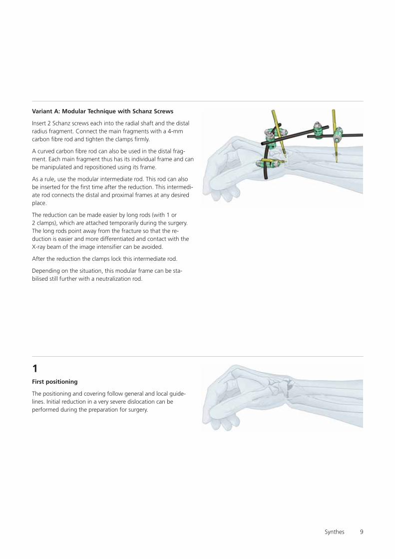
Variant A: Modular Technique with Schanz Screws
Insert 2 Schanz screws each into the radial shaft and the distalradius fragment. Connect the main fragments with a 4-mmcarbon fibre rod and tighten the clamps firmly.
A curved carbon fibre rod can also be used in the distal frag-ment. Each main fragment thus has its individual frame and canbe manipulated and repositioned using its frame.
As a rule, use the modular intermediate rod. This rod can alsobe inserted for the first time after the reduction. This intermedi-ate rod connects the distal and proximal frames at any desiredplace.
The reduction can be made easier by long rods (with 1 or2 clamps), which are attached temporarily during the surgery.The long rods point away from the fracture so that the re-duction is easier and more differentiated and contact with theX-ray beam of the image intensifier can be avoided.
After the reduction the clamps lock this intermediate rod.
Depending on the situation, this modular frame can be sta-bilised still further with a neutralization rod.
First positioning
The positioning and covering follow general and local guide-lines. Initial reduction in a very severe dislocation can beperformed during the preparation for surgery.
1

10
Inserting the screws in the radial shaft
Insert two Schanz screws in the radial shaft from the dorso-radial direction. Make sufficiently large stab incisions, spreadthe tissue to the bone, and push aside muscles, tendons,vessels, and nerves by feel and to some extent by sight.
Always insert the 3-part drill sleeve assembly until there issecure contact with the bone. Then implant the Schanz screws.
Note: When using Seldrill screws, merely drill in the screws.With conventional screws, first predrill holes and then insert thescrews. An angle of 10° to a maximum of 45° (in the radius)is recommended if the bones are thin. This is a benefit but notessential with weak bones. Select the pitch of the screws tofit the actual conditions.
It is recommended for the shaft that cooling be provided forthe drilling or insertion of the Seldrill Schanz screw. Toaccomplish this, the connector on the drill sleeve can be con-nected to a tube and a syringe.
2
Connecting the screws in the radial shaft
Connect the screws with a straight 4 mm carbon fibre rod. Theposition of the distal frame is readily evident.
The intermediate rod can also be selected “diagonally” throughthe Schanz screws, sometimes on the radial and sometimeson the ulnar side. A certain pitch results and the end collidesless with the distal frame. The projection relative to the fractureshould be 1 to 2 cm, so that there is room for a clamp.
Tighten all nuts firmly.
3

Synthes 11
Inserting screws in the distal fragment
Insert two Schanz screws in the safe zones between the tendonsand the vascular compartments of the distal fragment.Make adequate but not too large stab incisions at the correctplace.
Spread and push aside the soft tissues, tendons, nerves, andvessels until there is secure contact with the bone. Positionthe drill sleeve assembly (make sure that there is constantcontact with the bone) and insert the Schanz screws.
Note: Use self-drilling Seldrill screws without conventionalscrews with predrilling. Bear in mind the safe zones (seeanatomic diagram on page 8).
Schanz screws can be used with the modular technique in anymanner.
There are two variants of the surgical technique; these can bevaried at any time according to requirements.
Schanz screws at a 60 to 90° to each other, one from the radialand the other from the dorsal direction
4
4a
Small External FixatorNon-bridging – Variant A

12
Both Schanz screws from the radial direction
4b
Connecting screws in the distal fragment
Connect the two Schanz screws of the distal fragment. Use astraight 4-mm carbon fibre rod, a 4-mm steel rod, or a 4-mmcurved carbon fibre rod here. The last rod makes it easy toconnect the 2 Schanz screws elegantly around the soft tissue.
Note: The side on which the rod is placed is not important forthe surgical technique. Care must be taken that the frameconstruct of the distal fragment and the frame of the shaftfragment do not interfere with each other during the reductionmanoeuvre.
Tighten the nuts of the distal frame firmly. The nuts of both partial frames must be tightened well.
5
The further surgical technique is identical for a and b; this is anoutstanding feature of the modular technique.

Synthes 13
5bBoth Schanz screws radial
5a
The remaining surgical technique applies to both 5a and 5b.However, the technique is shown in the drawings only for 5a.
Small External FixatorNon-bridging – Variant A
Schanz screws at a 60 to 90° to each other, one radial and theother dorsal
Position of the Schanz screws in the distal fragment:

14
6Connecting the rods with the intermediate rod
Connect the partial frames with an intermediate rod. Differentmodular and freely selectable positions can be used.
Connections can be selected which can be assembled mosteasily due to anatomy, the pattern of injury, and construction.
The clamps of “the modular intermediate rod” must be keptopen until the reduction has been completed. But the clampsfor the individual frames must remain closed!
Synthes 15
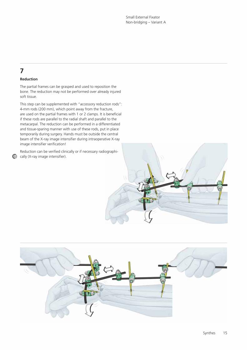
7Reduction
The partial frames can be grasped and used to reposition thebone. The reduction may not be performed over already injuredsoft tissue.
This step can be supplemented with “accessory reduction rods”:4-mm rods (200 mm), which point away from the fracture,are used on the partial frames with 1 or 2 clamps. It is beneficialif these rods are parallel to the radial shaft and parallel to themetacarpal. The reduction can be performed in a differentiatedand tissue-sparing manner with use of these rods, put in placetemporarily during surgery. Hands must be outside the centralbeam of the X-ray image intensifier during intraoperative X-rayimage intensifier verification!
Reduction can be verified clinically or if necessary radiographi-cally (X-ray image intensifier).
Small External FixatorNon-bridging – Variant A
Attaching the neutralization rod
A neutralization rod can provide the system with additionalstability.
It can be attached anywhere in the partial frame. Oneclamp per partial frame is sufficient. The use of an addi-tional clamp depends on various factors:
– the patient’s weight – fracture configuration / instability– distance to the fragment – the free lengths of the Schanz screws – the length of the modular intermediate rods
The more angled the rod and the greater the distances, theweaker and more elastic the construct. A neutralization rod canbe attached here for better stabilisation.
Finally, verify again whether all clamps have been tightened.
9
16
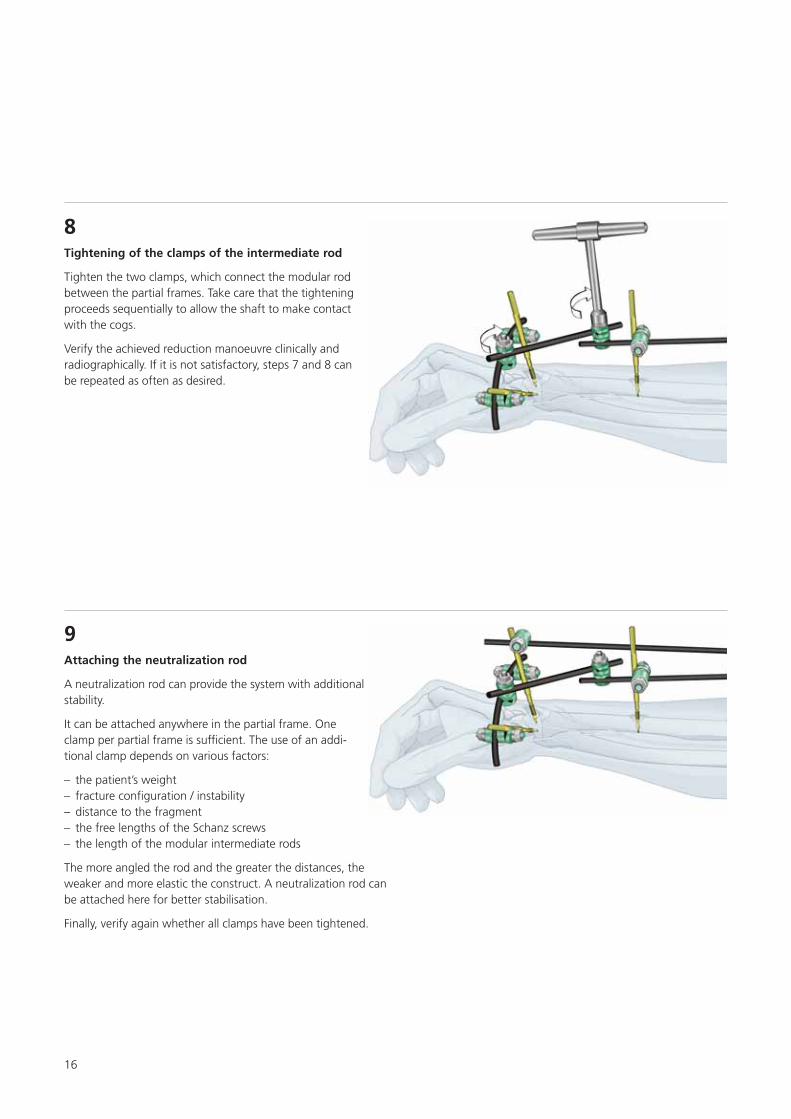
8Tightening of the clamps of the intermediate rod
Tighten the two clamps, which connect the modular rodbetween the partial frames. Take care that the tighteningproceeds sequentially to allow the shaft to make contactwith the cogs.
Verify the achieved reduction manoeuvre clinically andradiographically. If it is not satisfactory, steps 7 and 8 canbe repeated as often as desired.

Synthes 17
Variant B: with Kirschner wires
Before stabilising with Kirschner wires, reposition using thebridging technique. If a sufficient reduction can be achievedwith gentle pulling, the repositioning can be omitted.
In this variant, the frame for stabilising the fracture is config-ured according to the bridging surgical technique with thealready described modular technique.
The neutralization rod in step 9 usually does not need to beattached.
Small External FixatorNon-bridging – Variant B
2
Bridging modular technique for reduction
Perform steps 1 to 8 of the surgical technique of the bridgingvariant without prior reduction and temporary stabilisationusing the 3-rod modular technique.
1
Inserting the Kirschner wires
Insert 2, 3, or 4 Kirschner wires and stabilise the fracture.Bridge a intraarticular fracture with 1 Kirschner wire. Place theother two Kirschner wires from distal area into the shaft region.Connect all Kirschner wires with a curved carbon fibre rod.The ends of the Kirschner wires can be bent so that they pointin the same direction.

18
Removing part of the construct
Loosen the bridging and remove the front part of the construct.The construct now no longer bridges. The Kirschner wiresused in the distal fragment remain connected to the frame ofthe shaft fragment.
If the fracture is very unstable, the bridging construct can alsobe removed later.
Note: For instructional reasons, a diagram is not provided forthis procedure.
3
4Connecting the Kirschner wires
Connect all Kirschner wires using a rod.
Only minor fine reductions are possible with Kirschnerwires, which bridge the main fracture and open intothe shaft. These can be performed using the modulartechnique.
Synthes 19
Small External FixatorNon-bridging – Variant B
Connecting the partial frames
After making the connection between the Kirschner wires,tighten all clamps.
5
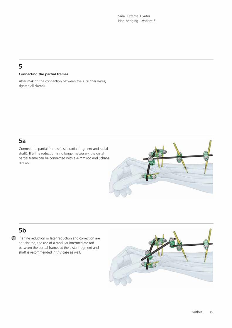
Connect the partial frames (distal radial fragment and radialshaft). If a fine reduction is no longer necessary, the distalpartial frame can be connected with a 4-mm rod and Schanzscrews.
5a
If a fine reduction or later reduction and correction areanticipated, the use of a modular intermediate rodbetween the partial frames at the distal fragment andshaft is recommended in this case as well.
5b

20
Attaching the neutralization rod
Depending on need and actual conditions, a neutral-ization rod can be attached between any places on anypartial frame.
This gives the system additional stability.
6
References
Jacob RP and Hertel R (1994) The Small AO External Fixator –A Versatile Device. Injury Vol. 25 Suppl. 4:X28–X34
Jenkins NH, Jones DG, Johnson SR, and Mintowt-Czyz WJ(1987) External Fixation of Colles’ Fractures. J Bone Joint SurgVol. 69-B no. 2 March:207–211
Jupiter JB and Diego LF (2001) Complications Following distalRadius Fractures. J Bone Joint Surg Am 83:1244–1265
McQueen MM and Mackenney PJ (1999) Bridging and Non-bridging External Fixation of Distal Radius Fractures.Orthopaedics Today, January/February:8
Weber KD, Raeder F, Brauer RB and Weiss S (2003) ExternalFxiation of Distal Radius Fractures: Four Compared with FivePins: A Randomized Prospecitive Study. J Bone Joint Surg Am85:660–666
Gradl G, Gierer P, Ewert A, Beck M and Mittlmeier T (2003)Der radio-radiale Fixateur am Handgelenk – eine Option zurfrühfunktionellen Behandlung der distalen Radiusfraktur.Zentralbl Chir 128(12):1014–9
References
Small External Fixator

0123 036.
000.
182
SM_7
0748
3 A
ASt
rate
c M
edic
al20
04Pr
inte
d in
Sw
itzer
land
LAG
Subj
ect
to m
odifi
catio
ns.
Manufacturer: Stratec MedicalEimattstrasse 3, CH-4436 Oberdorfwww.synthes.com Presented by: