suspension, arming, and releasing equipment · pdf filechapter 10 suspension, arming, and...
TRANSCRIPT
CHAPTER 10
SUSPENSION, ARMING, AND RELEASINGEQUIPMENT
The Navy uses complex suspension, arming, andreleasing devices in combat aircraft and weapons. Thehigh speed and performance of potential targets and ourown aircraft require the electronic operation ofsuspension, arming, and releasing equipment.
The equipment covered in this chapter is part of theaircraft search or kill stores systems. Generally, thesedevices operate electrically and are controlled byaircraft electrical circuits. A circuit-closing deviceactuates them manually by a hand switch orautomatically in the system.
BOMB RACKS
LEARNING OBJECTIVE: Identify thepurpose and use of bomb racks. Recognize thebomb racks used for various configurations,and identify the operation of bomb racks toinclude electrical and manual release andarming.
Aircraft bombs, torpedoes, mines, and other storesare suspended internally or externally from the aircraftby bomb racks. Bomb racks carry, arm, and releasestores.
Aero 1A Adapter Assembly
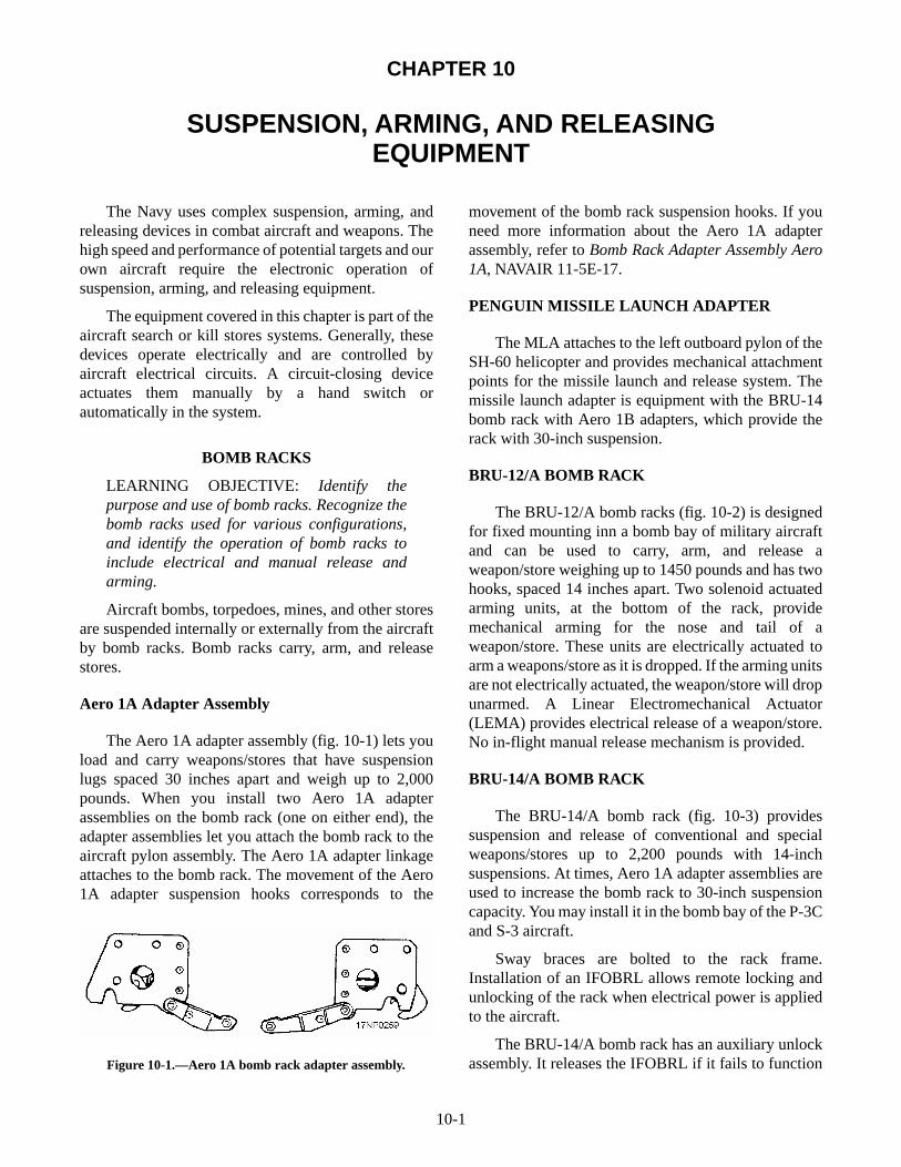
The Aero 1A adapter assembly (fig. 10-1) lets youload and carry weapons/stores that have suspensionlugs spaced 30 inches apart and weigh up to 2,000pounds. When you install two Aero 1A adapterassemblies on the bomb rack (one on either end), theadapter assemblies let you attach the bomb rack to theaircraft pylon assembly. The Aero 1A adapter linkageattaches to the bomb rack. The movement of the Aero1A adapter suspension hooks corresponds to the
movement of the bomb rack suspension hooks. If youneed more information about the Aero 1A adapterassembly, refer to Bomb Rack Adapter Assembly Aero1A, NAVAIR 11-5E-17.
PENGUIN MISSILE LAUNCH ADAPTER
The MLA attaches to the left outboard pylon of theSH-60 helicopter and provides mechanical attachmentpoints for the missile launch and release system. Themissile launch adapter is equipment with the BRU-14bomb rack with Aero 1B adapters, which provide therack with 30-inch suspension.
BRU-12/A BOMB RACK
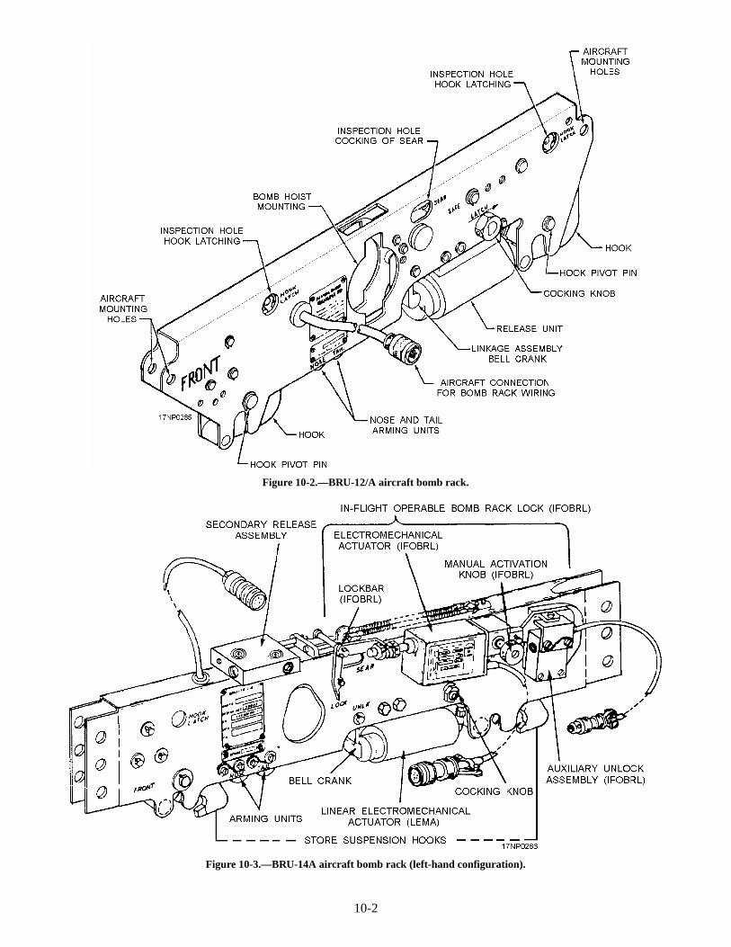
The BRU-12/A bomb racks (fig. 10-2) is designedfor fixed mounting inn a bomb bay of military aircraftand can be used to carry, arm, and release aweapon/store weighing up to 1450 pounds and has twohooks, spaced 14 inches apart. Two solenoid actuatedarming units, at the bottom of the rack, providemechanical arming for the nose and tail of aweapon/store. These units are electrically actuated toarm a weapons/store as it is dropped. If the arming unitsare not electrically actuated, the weapon/store will dropunarmed. A Linear Electromechanical Actuator(LEMA) provides electrical release of a weapon/store.No in-flight manual release mechanism is provided.
BRU-14/A BOMB RACK
The BRU-14/A bomb rack (fig. 10-3) providessuspension and release of conventional and specialweapons/stores up to 2,200 pounds with 14-inchsuspensions. At times, Aero 1A adapter assemblies areused to increase the bomb rack to 30-inch suspensioncapacity. You may install it in the bomb bay of the P-3Cand S-3 aircraft.
Sway braces are bolted to the rack frame.Installation of an IFOBRL allows remote locking andunlocking of the rack when electrical power is appliedto the aircraft.
The BRU-14/A bomb rack has an auxiliary unlockassembly. It releases the IFOBRL if it fails to function
10-1
Figure 10-1.—Aero 1A bomb rack adapter assembly.
10-2
Figure 10-2.—BRU-12/A aircraft bomb rack.
Figure 10-3.—BRU-14A aircraft bomb rack (left-hand configuration).
in the normal release mode. The auxiliary unlockassembly is a cartridge-actuated device (CAD) thatprovides a mounting point for the aft end of theIFOBRL. When actuated, the unlock assembly releasesthe IFOBRL and allows it to move forward. This freesthe sear link from restraint and lets the rack linkagefunction normally.
The BRU-14A bomb rack has a secondary releaseassembly. It initiates hook release if the LEMA fails tofunction. The secondary release assembly is a CAD thatconsists of a housing, piston, and release sliderassembly mounted on the top of the bomb rack frame.When actuated, the secondary release moves the searlink forward to release the bomb rack. The BRU-14/Adoesn't have remote manual-release capabilities.
If you want more information about the BRU-14/Abomb rack, refer to Bomb Rack BRU-14/A andBRU-15/A, NAVAIR 11-5E-18.
BRU-15/A BOMB RACK
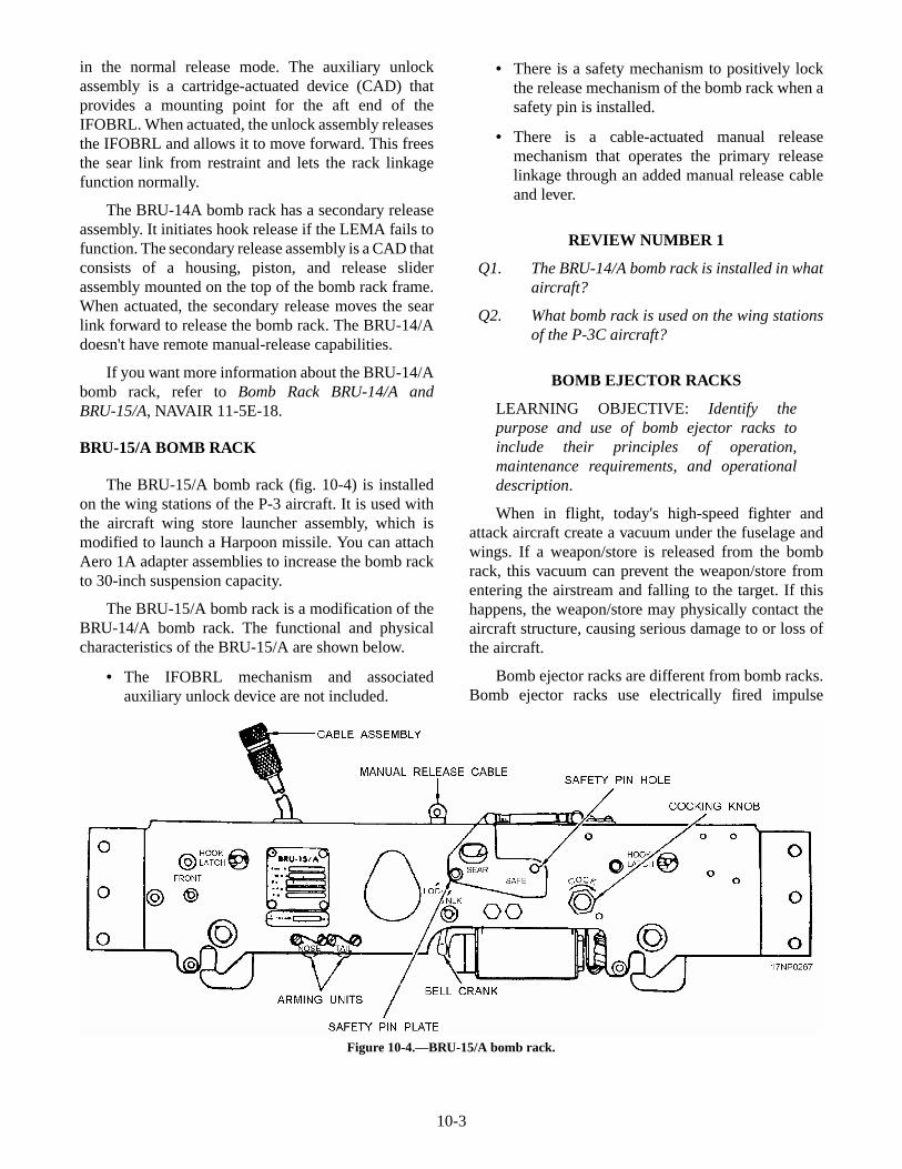
The BRU-15/A bomb rack (fig. 10-4) is installedon the wing stations of the P-3 aircraft. It is used withthe aircraft wing store launcher assembly, which ismodified to launch a Harpoon missile. You can attachAero 1A adapter assemblies to increase the bomb rackto 30-inch suspension capacity.
The BRU-15/A bomb rack is a modification of theBRU-14/A bomb rack. The functional and physicalcharacteristics of the BRU-15/A are shown below.
• The IFOBRL mechanism and associatedauxiliary unlock device are not included.
• There is a safety mechanism to positively lockthe release mechanism of the bomb rack when asafety pin is installed.
• There is a cable-actuated manual releasemechanism that operates the primary releaselinkage through an added manual release cableand lever.
REVIEW NUMBER 1
Q1. The BRU-14/A bomb rack is installed in whataircraft?
Q2. What bomb rack is used on the wing stationsof the P-3C aircraft?
BOMB EJECTOR RACKS
LEARNING OBJECTIVE: Identify thepurpose and use of bomb ejector racks toinclude their principles of operation,maintenance requirements, and operationaldescription.
When in flight, today's high-speed fighter andattack aircraft create a vacuum under the fuselage andwings. If a weapon/store is released from the bombrack, this vacuum can prevent the weapon/store fromentering the airstream and falling to the target. If thishappens, the weapon/store may physically contact theaircraft structure, causing serious damage to or loss ofthe aircraft.
Bomb ejector racks are different from bomb racks.Bomb ejector racks use electrically fired impulse
10-3
Figure 10-4.—BRU-15/A bomb rack.
cartridges to eject the weapon/store free of the bombracks. Bomb ejector racks eject the weapon/store fromthe bomb rack with sufficient force to overcomevacuum buildup and ensure a safe weapon/store-launching environment.
BRU-11A/A Bomb Ejector Rack
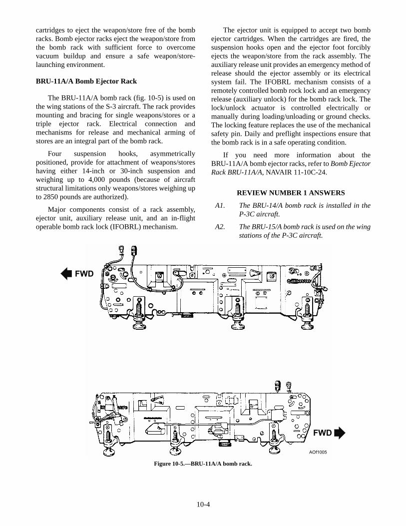
The BRU-11A/A bomb rack (fig. 10-5) is used onthe wing stations of the S-3 aircraft. The rack providesmounting and bracing for single weapons/stores or atriple ejector rack. Electrical connection andmechanisms for release and mechanical arming ofstores are an integral part of the bomb rack.
Four suspension hooks, asymmetricallypositioned, provide for attachment of weapons/storeshaving either 14-inch or 30-inch suspension andweighing up to 4,000 pounds (because of aircraftstructural limitations only weapons/stores weighing upto 2850 pounds are authorized).
Major components consist of a rack assembly,ejector unit, auxiliary release unit, and an in-flightoperable bomb rack lock (IFOBRL) mechanism.
The ejector unit is equipped to accept two bombejector cartridges. When the cartridges are fired, thesuspension hooks open and the ejector foot forciblyejects the weapon/store from the rack assembly. Theauxiliary release unit provides an emergency method ofrelease should the ejector assembly or its electricalsystem fail. The IFOBRL mechanism consists of aremotely controlled bomb rock lock and an emergencyrelease (auxiliary unlock) for the bomb rack lock. Thelock/unlock actuator is controlled electrically ormanually during loading/unloading or ground checks.The locking feature replaces the use of the mechanicalsafety pin. Daily and preflight inspections ensure thatthe bomb rack is in a safe operating condition.
If you need more information about theBRU-11A/A bomb ejector racks, refer to Bomb EjectorRack BRU-11A/A, NAVAIR 11-10C-24.
REVIEW NUMBER 1 ANSWERS
A1. The BRU-14/A bomb rack is installed in theP-3C aircraft.
A2. The BRU-15/A bomb rack is used on the wingstations of the P-3C aircraft.
10-4
FWD
FWD
AOf1005
Figure 10-5.—BRU-11A/A bomb rack.
REVIEW NUMBER 2
Q1. What is the maximum store capacity of theBRU-11A/A bomb ejector rack?
Q2. What does the auxiliary release unit provideson a BRU-11A/A?
BRU-32/A BOMB EJECTOR RACK
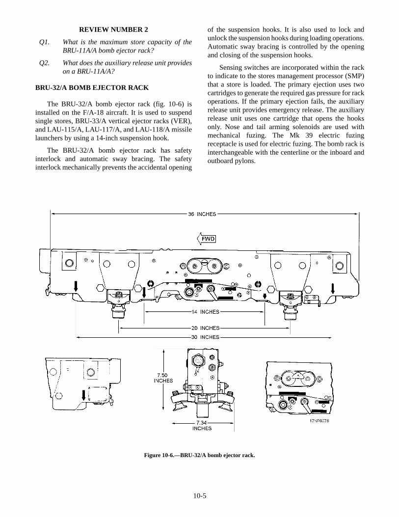
The BRU-32/A bomb ejector rack (fig. 10-6) isinstalled on the F/A-18 aircraft. It is used to suspendsingle stores, BRU-33/A vertical ejector racks (VER),and LAU-115/A, LAU-117/A, and LAU-118/A missilelaunchers by using a 14-inch suspension hook.
The BRU-32/A bomb ejector rack has safetyinterlock and automatic sway bracing. The safetyinterlock mechanically prevents the accidental opening
of the suspension hooks. It is also used to lock andunlock the suspension hooks during loading operations.Automatic sway bracing is controlled by the openingand closing of the suspension hooks.
Sensing switches are incorporated within the rackto indicate to the stores management processor (SMP)that a store is loaded. The primary ejection uses twocartridges to generate the required gas pressure for rackoperations. If the primary ejection fails, the auxiliaryrelease unit provides emergency release. The auxiliaryrelease unit uses one cartridge that opens the hooksonly. Nose and tail arming solenoids are used withmechanical fuzing. The Mk 39 electric fuzingreceptacle is used for electric fuzing. The bomb rack isinterchangeable with the centerline or the inboard andoutboard pylons.
10-5
Figure 10-6.—BRU-32/A bomb ejector rack.
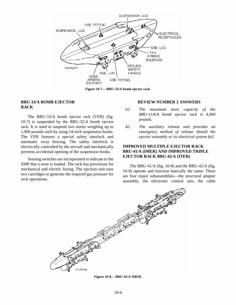
BRU-33/A BOMB EJECTORRACK
The BRU-33/A bomb ejector rack (VER) (fig.10-7) is suspended by the BRU-32/A bomb ejectorrack. It is used to suspend two stores weighing up to1,000 pounds each by using 14-inch suspension hooks.The VER features a special safety interlock andautomatic sway bracing. The safety interlock iselectrically controlled by the aircraft and mechanicallyprevents accidental opening of the suspension hooks.
Sensing switches are incorporated to indicate to theSMP that a store is loaded. The rack has provisions formechanical and electric fuzing. The ejection unit usestwo cartridges to generate the required gas pressure forrack operations.
REVIEW NUMBER 2 ANSWERS
A1. The maximum store capacity of theBRU-11A/A bomb ejector rack is 4,000pounds.
A2. The auxiliary release unit provides anemergency method of release should theejector assembly or its electrical system fail.
IMPROVED MULTIPLE EJECTOR RACKBRU-41/A (IMER) AND IMPROVED TRIPLEEJECTOR RACK BRU-42/A (ITER)
The BRU-41/A (fig. 10-8) and the BRU-42/A (fig.10-9) operate and function basically the same. Thereare four major subassemblies—the structural adapterassembly, the electronic control unit, the cable
10-6
Figure 10-7.—BRU-33/A bomb ejector rack.
Figure 10-8.—BRU-41/A IMER.
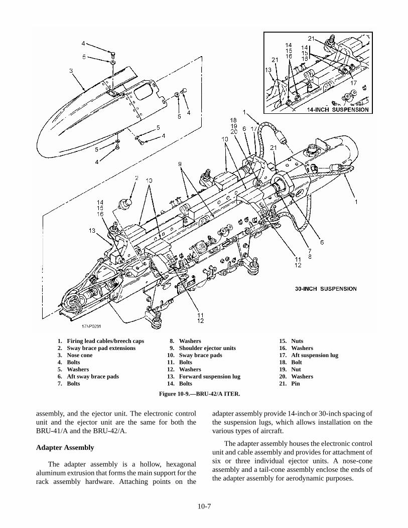
assembly, and the ejector unit. The electronic controlunit and the ejector unit are the same for both theBRU-41/A and the BRU-42/A.
Adapter Assembly
The adapter assembly is a hollow, hexagonalaluminum extrusion that forms the main support for therack assembly hardware. Attaching points on the
adapter assembly provide 14-inch or 30-inch spacing ofthe suspension lugs, which allows installation on thevarious types of aircraft.
The adapter assembly houses the electronic controlunit and cable assembly and provides for attachment ofsix or three individual ejector units. A nose-coneassembly and a tail-cone assembly enclose the ends ofthe adapter assembly for aerodynamic purposes.
10-7
1. Firing lead cables/breech caps2. Sway brace pad extensions3. Nose cone4. Bolts5. Washers6. Aft sway brace pads7. Bolts
8. Washers9. Shoulder ejector units
10. Sway brace pads11. Bolts12. Washers13. Forward suspension lug14. Bolts
15. Nuts16. Washers17. Aft suspension lug18. Bolt19. Nut20. Washers21. Pin
Figure 10-9.—BRU-42/A ITER.
Electronic Control Unit
The electronic control unit is a solid-stateelectronic control unit in a sealed container. Theelectronic control unit controls all the functions of thebomb rack and have the capability of releasing stores at35-millisecond intervals. The electronic control unit isdisposable. If it malfunctions, replace it with a new one.
Ejector Unit Assemblies
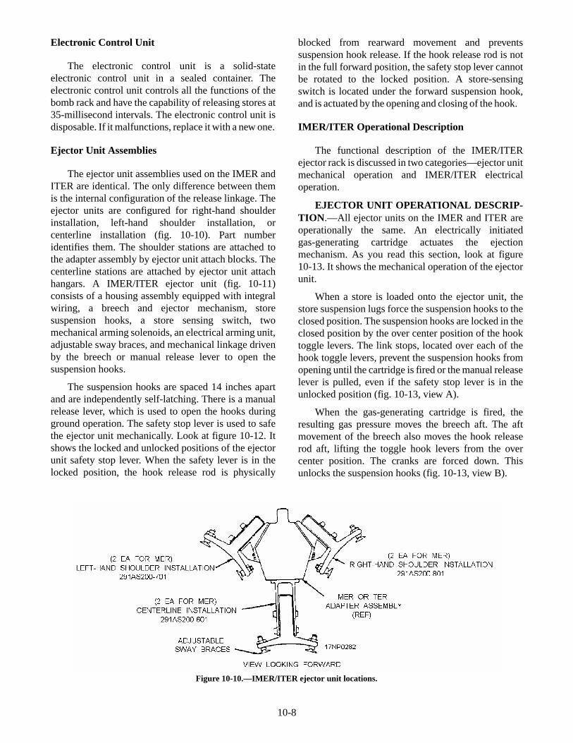
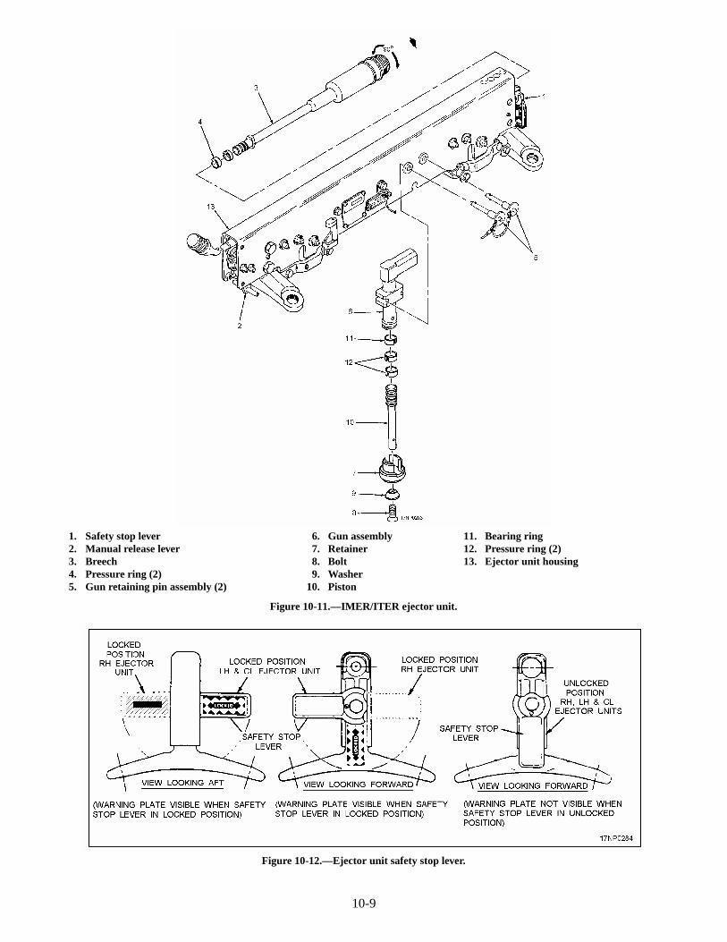
The ejector unit assemblies used on the IMER andITER are identical. The only difference between themis the internal configuration of the release linkage. Theejector units are configured for right-hand shoulderinstallation, left-hand shoulder installation, orcenterline installation (fig. 10-10). Part numberidentifies them. The shoulder stations are attached tothe adapter assembly by ejector unit attach blocks. Thecenterline stations are attached by ejector unit attachhangars. A IMER/ITER ejector unit (fig. 10-11)consists of a housing assembly equipped with integralwiring, a breech and ejector mechanism, storesuspension hooks, a store sensing switch, twomechanical arming solenoids, an electrical arming unit,adjustable sway braces, and mechanical linkage drivenby the breech or manual release lever to open thesuspension hooks.
The suspension hooks are spaced 14 inches apartand are independently self-latching. There is a manualrelease lever, which is used to open the hooks duringground operation. The safety stop lever is used to safethe ejector unit mechanically. Look at figure 10-12. Itshows the locked and unlocked positions of the ejectorunit safety stop lever. When the safety lever is in thelocked position, the hook release rod is physically
blocked from rearward movement and preventssuspension hook release. If the hook release rod is notin the full forward position, the safety stop lever cannotbe rotated to the locked position. A store-sensingswitch is located under the forward suspension hook,and is actuated by the opening and closing of the hook.
IMER/ITER Operational Description
The functional description of the IMER/ITERejector rack is discussed in two categories—ejector unitmechanical operation and IMER/ITER electricaloperation.
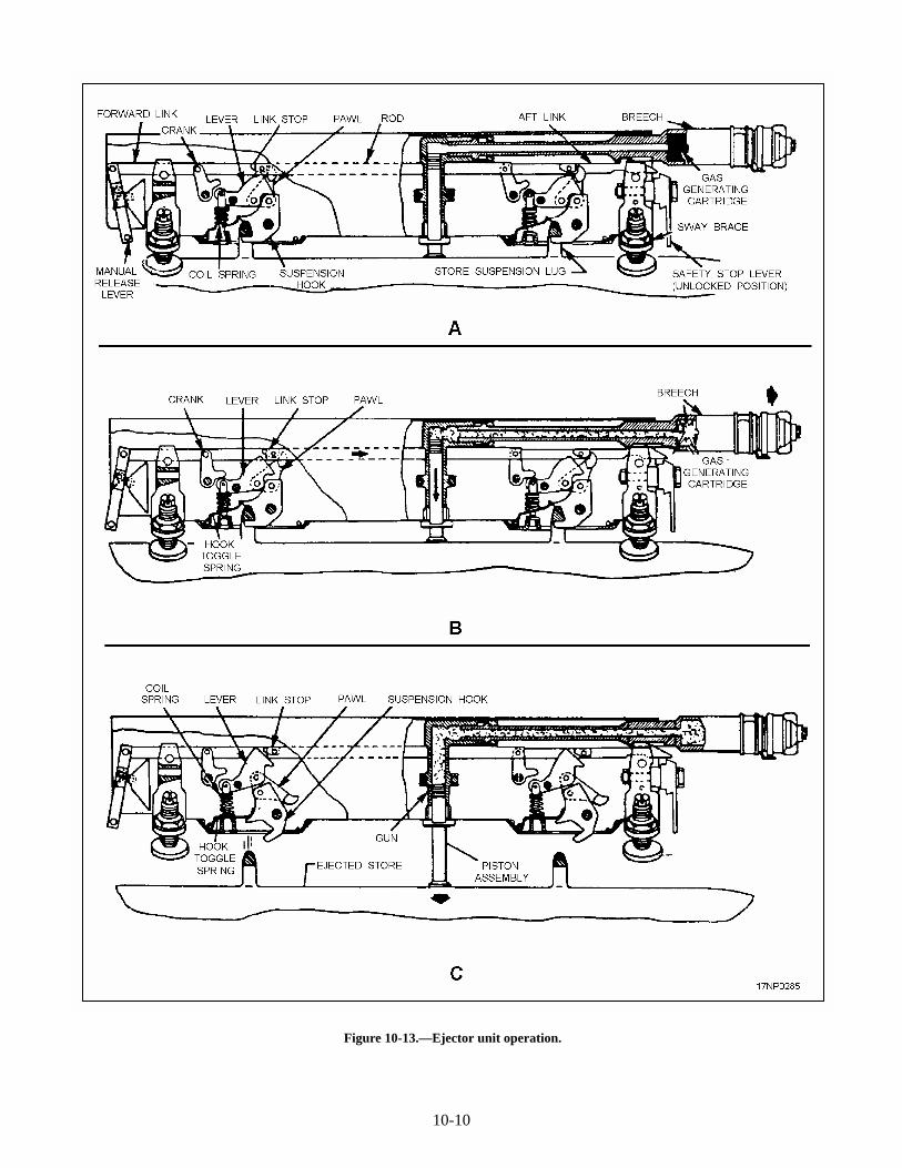
EJECTOR UNIT OPERATIONAL DESCRIP-TION.—All ejector units on the IMER and ITER areoperationally the same. An electrically initiatedgas-generating cartridge actuates the ejectionmechanism. As you read this section, look at figure10-13. It shows the mechanical operation of the ejectorunit.
When a store is loaded onto the ejector unit, thestore suspension lugs force the suspension hooks to theclosed position. The suspension hooks are locked in theclosed position by the over center position of the hooktoggle levers. The link stops, located over each of thehook toggle levers, prevent the suspension hooks fromopening until the cartridge is fired or the manual releaselever is pulled, even if the safety stop lever is in theunlocked position (fig. 10-13, view A).
When the gas-generating cartridge is fired, theresulting gas pressure moves the breech aft. The aftmovement of the breech also moves the hook releaserod aft, lifting the toggle hook levers from the overcenter position. The cranks are forced down. Thisunlocks the suspension hooks (fig. 10-13, view B).
10-8
Figure 10-10.—IMER/ITER ejector unit locations.
10-9
1. Safety stop lever2. Manual release lever3. Breech4. Pressure ring (2)5. Gun retaining pin assembly (2)
6. Gun assembly7. Retainer8. Bolt9. Washer
10. Piston
11. Bearing ring12. Pressure ring (2)13. Ejector unit housing
Figure 10-11.—IMER/ITER ejector unit.
Figure 10-12.—Ejector unit safety stop lever.
10-10
Figure 10-13.—Ejector unit operation.
Gas pressure from the cartridge acting against thegun piston, plus the weight of the store, forces theunlocked suspension hooks to open, releasing the store.The hooks are held in the open position by the hooktoggle spring and coil spring. The gun piston continuesto act against the store to provide positive separationfrom the ejector unit (fig. 10-13, view C).
IMER/ITER ELECTRICAL OPERATION.—Before discussing the electrical operation of theIMER/ITER, you must understand the function ofseveral electrical components. These components arebriefly discussed in the following paragraphs.
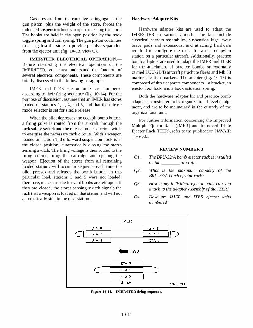
IMER and ITER ejector units are numberedaccording to their firing sequence (fig. 10-14). For thepurpose of discussion, assume that an IMER has storesloaded on stations 1, 2, 4, and 6, and that the releasemode selector is set for single release.
When the pilot depresses the cockpit bomb button,a firing pulse is routed from the aircraft through therack safety switch and the release mode selector switchto energize the necessary rack circuits. With a weaponloaded on station 1, the forward suspension hook is inthe closed position, automatically closing the storessensing switch. The firing voltage is then routed to thefiring circuit, firing the cartridge and ejecting theweapon. Ejection of the stores from all remainingloaded stations will occur in sequence each time thepilot presses and releases the bomb button. In thisparticular load, stations 3 and 5 were not loaded;therefore, make sure the forward hooks are left open. Ifthey are closed, the stores sensing switch signals therack that a weapon is loaded on that station and will notautomatically step to the next station.
Hardware Adapter Kits
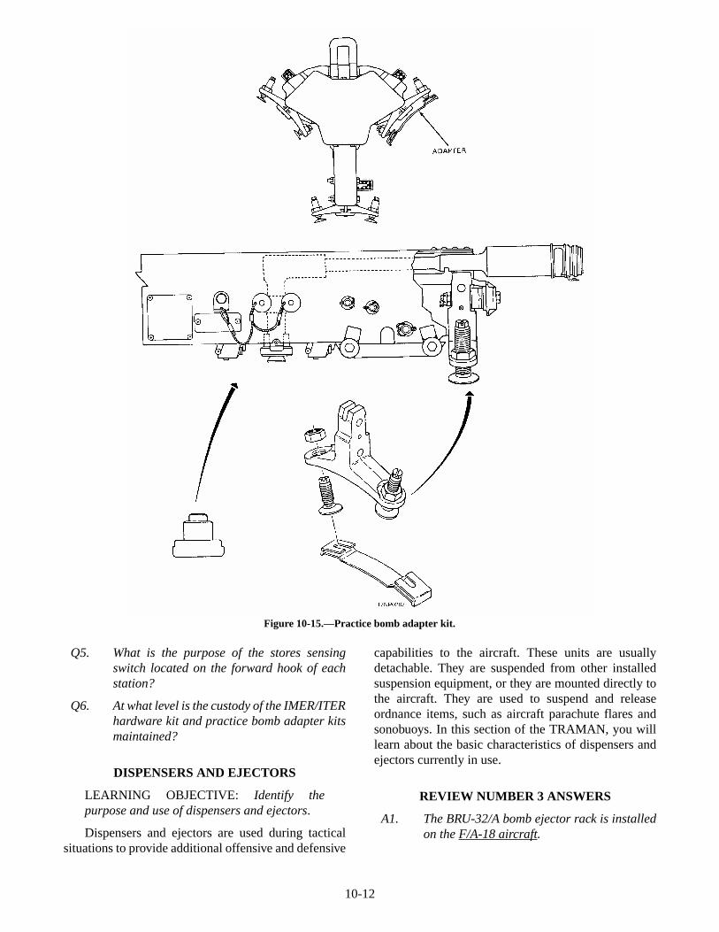
Hardware adapter kits are used to adapt theIMER/ITER to various aircraft. The kits includeelectrical harness assemblies, suspension lugs, swaybrace pads and extensions, and attaching hardwarerequired to configure the racks for a desired pylonstation on a particular aircraft. Additionally, practicebomb adapters are used to adapt the IMER and ITERfor the attachment of practice bombs or externallycarried LUU-2B/B aircraft parachute flares and Mk 58marine location markers. The adapter (fig. 10-15) iscomposed of three separate components—a bracket, anejector foot lock, and a hook actuation spring.
Both the hardware adapter kit and practice bombadapter is considered to be organizational-level equip-ment, and are to be maintained in the custody of theorganizational unit.
For further information concerning the ImprovedMultiple Ejector Rack (IMER) and Improved TripleEjector Rack (ITER), refer to the publication NAVAIR11-5-603.
REVIEW NUMBER 3
Q1. The BRU-32/A bomb ejector rack is installedon the ________ aircraft.
Q2. What is the maximum capacity of theBRU-33/A bomb ejector rack?
Q3. How many individual ejector units can youattach to the adapter assembly of the ITER?
Q4. How are IMER and ITER ejector unitsnumbered?
10-11
Figure 10-14.—IMER/ITER firing sequence.
Q5. What is the purpose of the stores sensingswitch located on the forward hook of eachstation?
Q6. At what level is the custody of the IMER/ITERhardware kit and practice bomb adapter kitsmaintained?
DISPENSERS AND EJECTORS
LEARNING OBJECTIVE: Identify thepurpose and use of dispensers and ejectors.
Dispensers and ejectors are used during tacticalsituations to provide additional offensive and defensive
capabilities to the aircraft. These units are usuallydetachable. They are suspended from other installedsuspension equipment, or they are mounted directly tothe aircraft. They are used to suspend and releaseordnance items, such as aircraft parachute flares andsonobuoys. In this section of the TRAMAN, you willlearn about the basic characteristics of dispensers andejectors currently in use.
REVIEW NUMBER 3 ANSWERS
A1. The BRU-32/A bomb ejector rack is installedon the F/A-18 aircraft.
10-12
Figure 10-15.—Practice bomb adapter kit.
A2. The maximum capacity of the BRU-33/Abomb ejector rack is 2,000 pounds.
A3. You can attach three individual ejector unitsto the adapter assembly of the ITER.
A4. The IMER and ITER ejector units arenumbered according to the firing sequence.
A5. The stores sensing switch, located on theforward hook of each station, signals the rackwhether a weapon is loaded on a particularstation or not. If the forward hook is closed,the switch signals the rack that the station isloaded, and will not automatically step to thenext station.
A6. Custody of the IMER/ITER hardware kit andpractice bomb adapter kits is maintained atthe organizational level.
SUU-25F/A DISPENSER
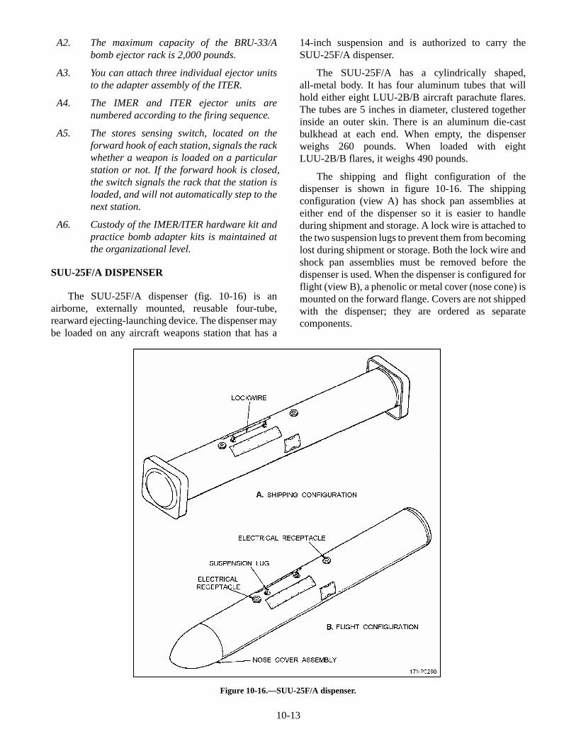
The SUU-25F/A dispenser (fig. 10-16) is anairborne, externally mounted, reusable four-tube,rearward ejecting-launching device. The dispenser maybe loaded on any aircraft weapons station that has a
14-inch suspension and is authorized to carry theSUU-25F/A dispenser.
The SUU-25F/A has a cylindrically shaped,all-metal body. It has four aluminum tubes that willhold either eight LUU-2B/B aircraft parachute flares.The tubes are 5 inches in diameter, clustered togetherinside an outer skin. There is an aluminum die-castbulkhead at each end. When empty, the dispenserweighs 260 pounds. When loaded with eightLUU-2B/B flares, it weighs 490 pounds.
The shipping and flight configuration of thedispenser is shown in figure 10-16. The shippingconfiguration (view A) has shock pan assemblies ateither end of the dispenser so it is easier to handleduring shipment and storage. A lock wire is attached tothe two suspension lugs to prevent them from becominglost during shipment or storage. Both the lock wire andshock pan assemblies must be removed before thedispenser is used. When the dispenser is configured forflight (view B), a phenolic or metal cover (nose cone) ismounted on the forward flange. Covers are not shippedwith the dispenser; they are ordered as separatecomponents.
10-13
Figure 10-16.—SUU-25F/A dispenser.
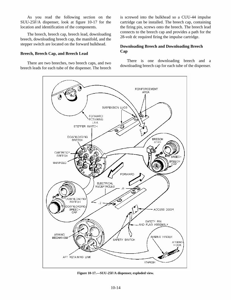
As you read the following section on theSUU-25F/A dispenser, look at figure 10-17 for thelocation and identification of the components.
The breech, breech cap, breech lead, downloadingbreech, downloading breech cap, the manifold, and thestepper switch are located on the forward bulkhead.
Breech, Breech Cap, and Breech Lead
There are two breeches, two breech caps, and twobreech leads for each tube of the dispenser. The breech
is screwed into the bulkhead so a CUU-44 impulsecartridge can be installed. The breech cap, containingthe firing pin, screws onto the breech. The breech leadconnects to the breech cap and provides a path for the28-volt dc required firing the impulse cartridge.
Downloading Breech and Downloading BreechCap
There is one downloading breech and adownloading breech cap for each tube of the dispenser.
10-14
Figure 10-17.—SUU-25F/A dispenser, exploded view.

The downloading breech mounts to the bulkhead. Thedownloading breech cap screws onto the downloadingbreech. With the downloading breech cap removed, thedownloading breech lets you insert the loading,unloading, cleaning, push rod tool so the stores can beeasily removed during downloading procedures. It alsoprevents air pressure buildup in the tubes whenuploading stores. Reinstall the downloading breechcaps after the loading or unloading procedures havebeen completed.
Manifold
The manifold has eight manifold breech leadreceptacles for connection of the breech leads. It alsohas two test socket assemblies you can use duringdispenser electrical test procedures.
Stepper Switch
The stepper switch provides sequential firing of theimpulse cartridges. The switch has 10 functionalsettings—one safe setting, one arm setting, and eightfiring steps. Always place the stepper switch in the safeposition during dispenser loading and unloading. Movethe switch to the arm position during aircraft armingprocedures just before flight.
Forward and Aft Retaining Lock
Each of the four dispenser tubes contains a forwardretaining lock, an aft retaining lock, and an armingmechanism.
The forward and aft retaining locks, when in thelocked position, protrude into the dispenser tube. Thisprevents loaded stores from being inadvertently ejectedby the forces during aircraft catapult launches.
The forward retaining lock is located between thedispenser outer skin and the tube near the midpoint ofthe dispenser. You can move the retainer lock from theeither the locked or unlocked position through anaccess door located on either side of the dispenser.Before loading a store, rotate the retaining lock to theunlocked position. This pivots the retainer lock out ofthe tube. After the store has been loaded, rotate theretaining lock to the locked position, and secure it byinstalling a shear pin. The forward retaining lockretains the forward-loaded store only.
The aft retaining lock is attached to the aft bulkheadand retains the aft loaded store. It is also secured in thelocked position by installing a shear pin.
Arming Mechanism
The arming mechanism is located in the aft end ofthe dispenser tube. The arming mechanism initiates thearming sequence of a store as it is ejected from the tube.
The dispenser is suspended by two screw-type lugsspaced 14 inches apart. The area around the suspensionlugs has a hardback reinforcement to permit swaybracing and forced ejection of the dispenser.
Two electrical receptacles, V1 and V2, are locatedforward and aft of the suspension lugs, respectively.Both receptacles give you a way to electrically connectthe dispenser to the aircraft weapons control system.Only one receptacle is used at a time. The electricalconfiguration of the rack determines the receptacle youwill use.
An electrical wiring harness is routed internallyfrom electrical connectors V1 and V2 to the stepperswitch. A safety switch that is normally in the closedposition interrupts the wiring harness. When the safetypin and flag assembly is inserted, the safety switch isheld in the open position and the electrical circuits aregrounded, making the dispenser electrically safe.
Functional Description
When you load a dispenser tube with munitions,each pair of flares are configured with an ADU-381/Aflare adapter kit.
A yellow-colored sealing ring is pressed on eachend of the munition as a seal between the munition andthe tube body. This prevents gas pressure from escapingduring ejection. A green-colored arming cap is installedon the timer end of a flare or on the rotochute end of asonobuoy. The green arming cap lanyard is connectedto the timer knob of the flare, and then pressed on overthe flange of the sealing ring. Mount a whitecross-shaped plastic spacer on the aft sealing ring of theforward munition. This provides enough space betweenthe forward and aft munition to provide an expansionchamber for ejecting the aft munition.
After you have installed the adapter, install themunitions in the dispenser tube.
When an SUU-25F/A dispenser is fully loaded anduploaded on the aircraft, the pilot may eject flares. Thepilot must first select the weapons control system, andthen trigger the dispensing switch. A 28-volt dcelectrical signal passes through an electrical cable fromthe aircraft to either receptacle J1 or J2 of the dispenser.The signal is routed from the dispenser receptacle to the
10-15
stepper switch, causing the stepper switch to step fromthe preset ARM position to the No. 1 position. Thisfires the No. 1 impulse cartridge. The gas pressure,generated by the fired cartridge, is ported through a gastube, internally along the side of the dispenser, into theaft expansion chamber ahead of the aft flare.
As the gas pressure increases, the aft retaining lockshear pin is cut, allowing the aft flare to eject. As thetimer end of the flare approaches the rear of the tube,the arming finger of the arming mechanism engages theyellow sealing ring. The sealing ring cams the armingfinger down, which, in turn, cams the arming hook up toengage the green arming cap. This action allows theflare to extend the lanyard. The lanyard extracts thetimer knob and arms or starts the flare functioningsequence.
When the pilot triggers the system again, thestepper switch steps to the No. 2 position and fires thecartridge. This meters the gas pressure directly into theforward expansion chamber. As the gas pressureincreases, the forward retaining lock shear pin is cut.This allows the forward flare to be dispensed in thesame manner as the aft flare. If the aft flare failed toeject, the gas pressure generated for ejecting theforward flare produces sufficient gas pressure to purgeboth flares out of the tube.
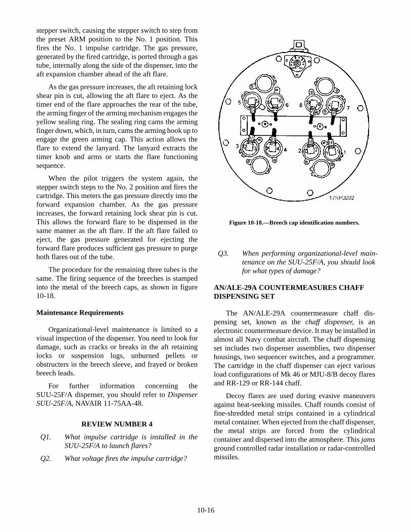
The procedure for the remaining three tubes is thesame. The firing sequence of the breeches is stampedinto the metal of the breech caps, as shown in figure10-18.
Maintenance Requirements
Organizational-level maintenance is limited to avisual inspection of the dispenser. You need to look fordamage, such as cracks or breaks in the aft retaininglocks or suspension lugs, unburned pellets orobstructers in the breech sleeve, and frayed or brokenbreech leads.
For further information concerning theSUU-25F/A dispenser, you should refer to DispenserSUU-25F/A, NAVAIR 11-75AA-48.
REVIEW NUMBER 4
Q1. What impulse cartridge is installed in theSUU-25F/A to launch flares?
Q2. What voltage fires the impulse cartridge?
Q3. When performing organizational-level main-tenance on the SUU-25F/A, you should lookfor what types of damage?
AN/ALE-29A COUNTERMEASURES CHAFFDISPENSING SET
The AN/ALE-29A countermeasure chaff dis-pensing set, known as the chaff dispenser, is anelectronic countermeasure device. It may be installed inalmost all Navy combat aircraft. The chaff dispensingset includes two dispenser assemblies, two dispenserhousings, two sequencer switches, and a programmer.The cartridge in the chaff dispenser can eject variousload configurations of Mk 46 or MJU-8/B decoy flaresand RR-129 or RR-144 chaff.
Decoy flares are used during evasive maneuversagainst heat-seeking missiles. Chaff rounds consist offine-shredded metal strips contained in a cylindricalmetal container. When ejected from the chaff dispenser,the metal strips are forced from the cylindricalcontainer and dispersed into the atmosphere. This jamsground controlled radar installation or radar-controlledmissiles.
10-16
Figure 10-18.—Breech cap identification numbers.
Dispenser Assemblies
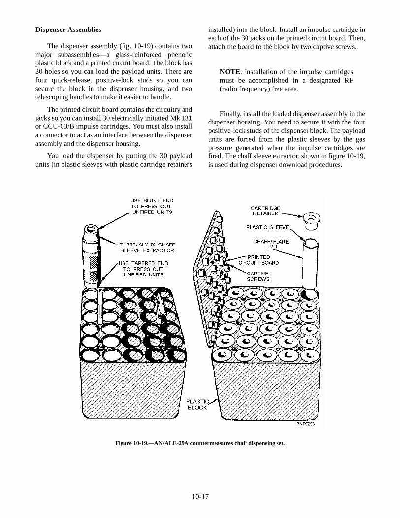
The dispenser assembly (fig. 10-19) contains twomajor subassemblies—a glass-reinforced phenolicplastic block and a printed circuit board. The block has30 holes so you can load the payload units. There arefour quick-release, positive-lock studs so you cansecure the block in the dispenser housing, and twotelescoping handles to make it easier to handle.
The printed circuit board contains the circuitry andjacks so you can install 30 electrically initiated Mk 131or CCU-63/B impulse cartridges. You must also installa connector to act as an interface between the dispenserassembly and the dispenser housing.
You load the dispenser by putting the 30 payloadunits (in plastic sleeves with plastic cartridge retainers
installed) into the block. Install an impulse cartridge ineach of the 30 jacks on the printed circuit board. Then,attach the board to the block by two captive screws.
NOTE: Installation of the impulse cartridgesmust be accomplished in a designated RF(radio frequency) free area.
Finally, install the loaded dispenser assembly in thedispenser housing. You need to secure it with the fourpositive-lock studs of the dispenser block. The payloadunits are forced from the plastic sleeves by the gaspressure generated when the impulse cartridges arefired. The chaff sleeve extractor, shown in figure 10-19,is used during dispenser download procedures.
10-17
Figure 10-19.—AN/ALE-29A countermeasures chaff dispensing set.
Dispenser Housings
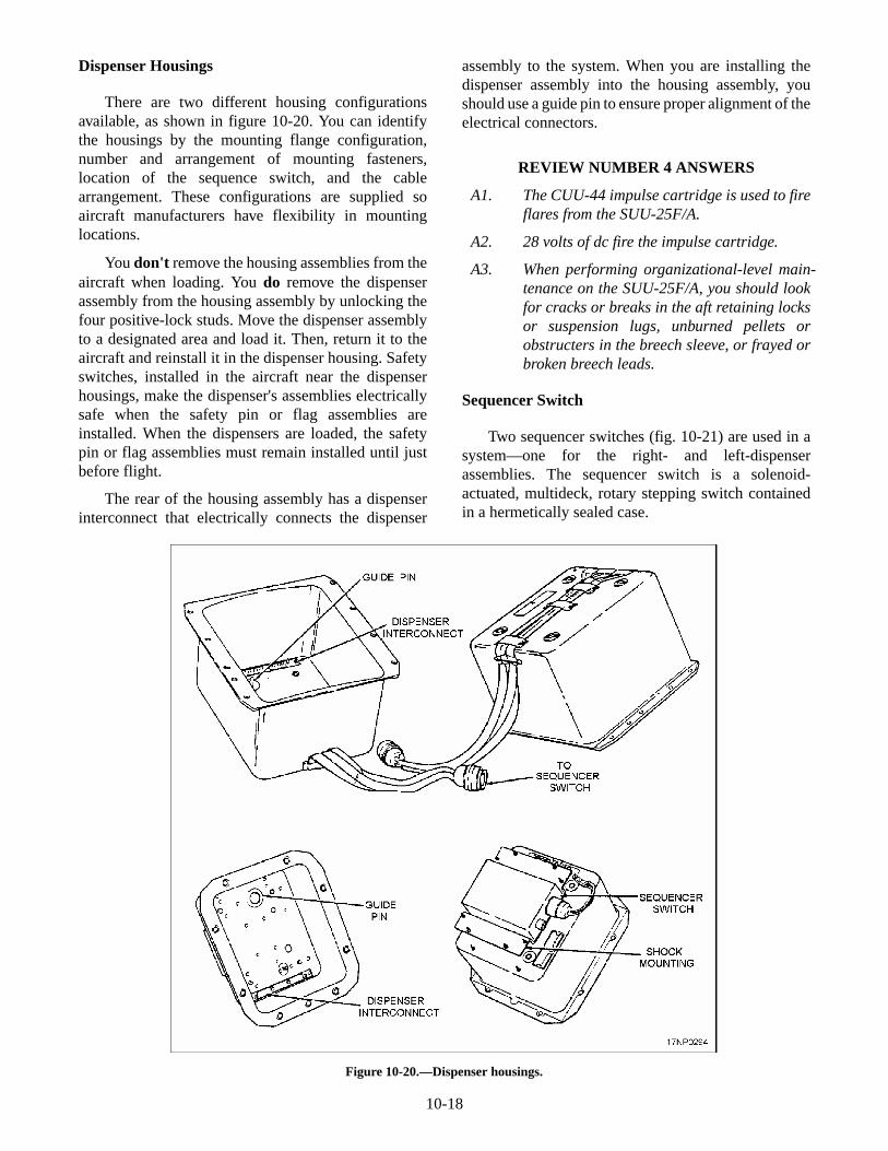
There are two different housing configurationsavailable, as shown in figure 10-20. You can identifythe housings by the mounting flange configuration,number and arrangement of mounting fasteners,location of the sequence switch, and the cablearrangement. These configurations are supplied soaircraft manufacturers have flexibility in mountinglocations.
You don't remove the housing assemblies from theaircraft when loading. You do remove the dispenserassembly from the housing assembly by unlocking thefour positive-lock studs. Move the dispenser assemblyto a designated area and load it. Then, return it to theaircraft and reinstall it in the dispenser housing. Safetyswitches, installed in the aircraft near the dispenserhousings, make the dispenser's assemblies electricallysafe when the safety pin or flag assemblies areinstalled. When the dispensers are loaded, the safetypin or flag assemblies must remain installed until justbefore flight.
The rear of the housing assembly has a dispenserinterconnect that electrically connects the dispenser
assembly to the system. When you are installing thedispenser assembly into the housing assembly, youshould use a guide pin to ensure proper alignment of theelectrical connectors.
REVIEW NUMBER 4 ANSWERS
A1. The CUU-44 impulse cartridge is used to fireflares from the SUU-25F/A.
A2. 28 volts of dc fire the impulse cartridge.
A3. When performing organizational-level main-tenance on the SUU-25F/A, you should lookfor cracks or breaks in the aft retaining locksor suspension lugs, unburned pellets orobstructers in the breech sleeve, or frayed orbroken breech leads.
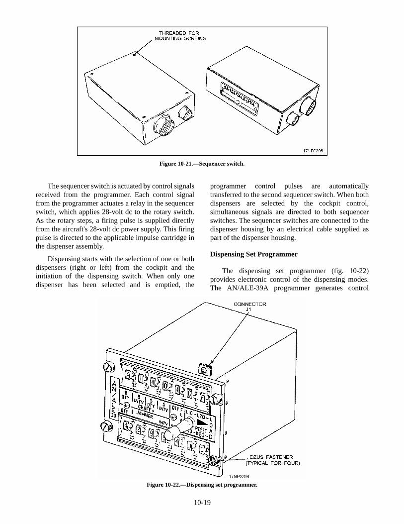
Sequencer Switch
Two sequencer switches (fig. 10-21) are used in asystem—one for the right- and left-dispenserassemblies. The sequencer switch is a solenoid-actuated, multideck, rotary stepping switch containedin a hermetically sealed case.
10-18
Figure 10-20.—Dispenser housings.
The sequencer switch is actuated by control signalsreceived from the programmer. Each control signalfrom the programmer actuates a relay in the sequencerswitch, which applies 28-volt dc to the rotary switch.As the rotary steps, a firing pulse is supplied directlyfrom the aircraft's 28-volt dc power supply. This firingpulse is directed to the applicable impulse cartridge inthe dispenser assembly.
Dispensing starts with the selection of one or bothdispensers (right or left) from the cockpit and theinitiation of the dispensing switch. When only onedispenser has been selected and is emptied, the
programmer control pulses are automaticallytransferred to the second sequencer switch. When bothdispensers are selected by the cockpit control,simultaneous signals are directed to both sequencerswitches. The sequencer switches are connected to thedispenser housing by an electrical cable supplied aspart of the dispenser housing.
Dispensing Set Programmer
The dispensing set programmer (fig. 10-22)provides electronic control of the dispensing modes.The AN/ALE-39A programmer generates control
10-19
Figure 10-21.—Sequencer switch.
Figure 10-22.—Dispensing set programmer.
signals for the programmed payload ejectionsequences. It also generates control signals for singleejection of payloads initiated manually. Manual(single) dispensing is performed during a programmeddispensing sequence without disrupting the program.
AN/ALE-37A COUNTERMEASURES CHAFFDISPENSING SET
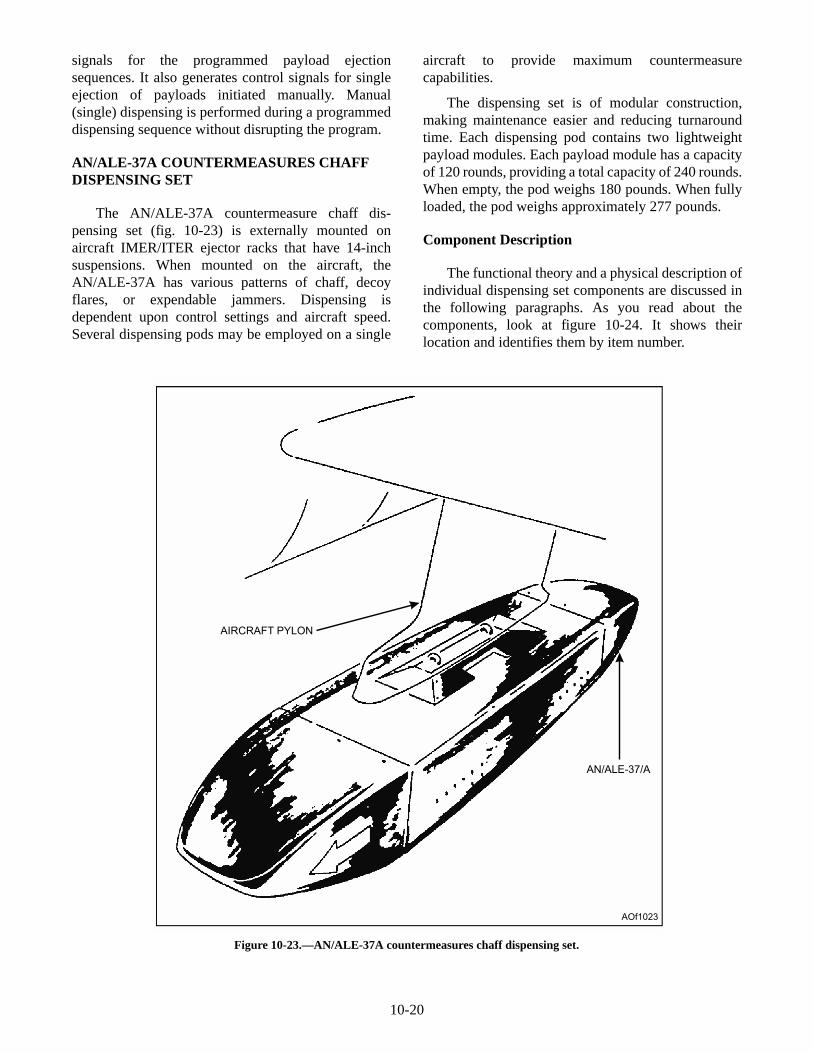
The AN/ALE-37A countermeasure chaff dis-pensing set (fig. 10-23) is externally mounted onaircraft IMER/ITER ejector racks that have 14-inchsuspensions. When mounted on the aircraft, theAN/ALE-37A has various patterns of chaff, decoyflares, or expendable jammers. Dispensing isdependent upon control settings and aircraft speed.Several dispensing pods may be employed on a single
aircraft to provide maximum countermeasurecapabilities.
The dispensing set is of modular construction,making maintenance easier and reducing turnaroundtime. Each dispensing pod contains two lightweightpayload modules. Each payload module has a capacityof 120 rounds, providing a total capacity of 240 rounds.When empty, the pod weighs 180 pounds. When fullyloaded, the pod weighs approximately 277 pounds.
Component Description
The functional theory and a physical description ofindividual dispensing set components are discussed inthe following paragraphs. As you read about thecomponents, look at figure 10-24. It shows theirlocation and identifies them by item number.
10-20
AIRCRAFT PYLON
AN/ALE-37/A
AOf1023
Figure 10-23.—AN/ALE-37A countermeasures chaff dispensing set.
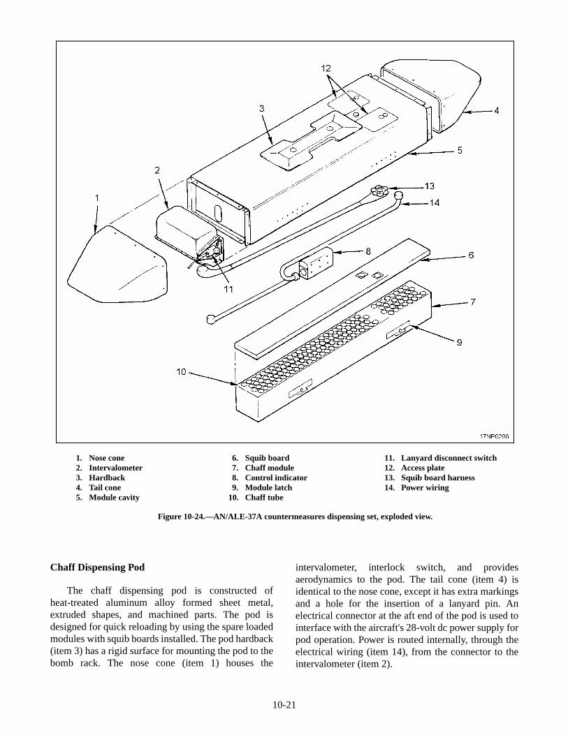
Chaff Dispensing Pod
The chaff dispensing pod is constructed ofheat-treated aluminum alloy formed sheet metal,extruded shapes, and machined parts. The pod isdesigned for quick reloading by using the spare loadedmodules with squib boards installed. The pod hardback(item 3) has a rigid surface for mounting the pod to thebomb rack. The nose cone (item 1) houses the
intervalometer, interlock switch, and providesaerodynamics to the pod. The tail cone (item 4) isidentical to the nose cone, except it has extra markingsand a hole for the insertion of a lanyard pin. Anelectrical connector at the aft end of the pod is used tointerface with the aircraft's 28-volt dc power supply forpod operation. Power is routed internally, through theelectrical wiring (item 14), from the connector to theintervalometer (item 2).
10-21
1. Nose cone2. Intervalometer3. Hardback4. Tail cone5. Module cavity
6. Squib board7. Chaff module8. Control indicator9. Module latch
10. Chaff tube
11. Lanyard disconnect switch12. Access plate13. Squib board harness14. Power wiring
Figure 10-24.—AN/ALE-37A countermeasures dispensing set, exploded view.
Chaff Module
You load the chaff module (item 7) with chaff,decoy flares, jammers, or a mixture of these payloadsand a squib board (item 6). Then, insert it into themodule cavity (item 5). Secure the chaff module in thecavity by locking the four positive locking latches (item9). The 120 chaff tubes (item 10) contain the payloads.Each pod houses two separate modules.
Squib Board
The squib board (item 6) has four layers fastenedand bonded together. The top layer is a thin sheet metalcover. The second layer is composed of edge spacers toprovide a wire cavity for squib circuits. The remaininglayers are composed of electrical insulating andfire-retardant materials. Two 61-pin electricalconnectors connect the squib board harness (item 13) tothe intervalometer circuitry. Place the squib board, with120 Mk 131 or CCU-63/B impulse cartridges inserted,on top of the chaff module and secure it with eightcaptive attachment screws.
Intervalometer
The intervalometer (item 2) is used to control theburst rate. The intervalometer circuitry responds to thesettings on the pod control indicator or the cockpit
control indicator. The intervalometer contains asolid-state component electronic timing pulsar toswitch the two automatic stepping switches. Thestepping switches will operate individually for singlesfiring or in parallel for doubles firing.
Lanyard Disconnect Switch
The lanyard disconnect switch (item 11) is the mainsafety feature preventing cartridge detonation duringchaff loading and ground maintenance. The switch isnormally in the closed position. It is deactivated(opened) by inserting the lanyard pin in the switchsocket. With the pin inserted, the lanyard disconnectswitch opens the intervalometer circuitry and removesthe electrical path to the squib board circuits.
Access Plates
The two access plates (item 12) provide access tothe pod electrical connectors.
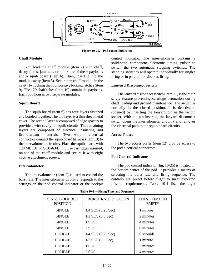
Pod Control Indicator
The pod control indicator (fig. 10-25) is located onthe bottom center of the pod. It provides a means ofselecting the burst rate and firing sequence. Thecontrols are preset before flight to meet expectedmission requirements. Table 10-1 lists the eight
10-22
Figure 10-25.—Pod control indicator.
SINGLE-DOUBLEPOSITION
BURST RATE POSITION TOTAL TIME TOEMPTY
SINGLE
SINGLE
SINGLE
SINGLE
DOUBLE
DOUBLE
DOUBLE
DOUBLE
1/4 SEC (0.25 Sec)
1/2 SEC (0.5 Sec)
1 SEC
2 SEC
1/4 SEC (0.25 Sec)
1/2 SEC (0.5 Sec)
1 SEC
2 SEC
1 minute
2 minutes
4 minutes
8 minutes
30 seconds
1 minute
2 minutes
4 minutes
Table 10-1.—Firing Time and Sequence
combinations of firing that can be obtained bypositioning of the two rotary selector switches (BURSTRATE and SINGLE/DOUBLE) on the pod controlindicator. There is also a reset switch and reset lightindicator on the pod control indicator so theintervalometer can be recycled to the startingposition.
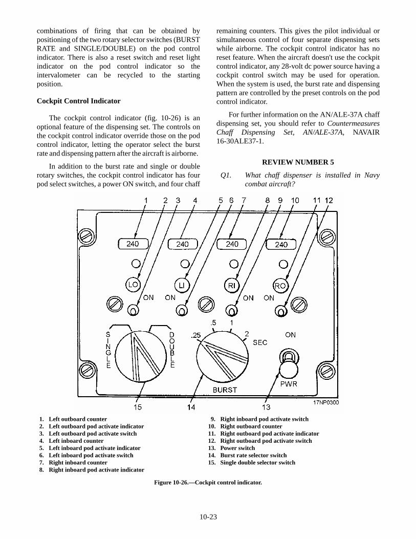
Cockpit Control Indicator
The cockpit control indicator (fig. 10-26) is anoptional feature of the dispensing set. The controls onthe cockpit control indicator override those on the podcontrol indicator, letting the operator select the burstrate and dispensing pattern after the aircraft is airborne.
In addition to the burst rate and single or doublerotary switches, the cockpit control indicator has fourpod select switches, a power ON switch, and four chaff
remaining counters. This gives the pilot individual orsimultaneous control of four separate dispensing setswhile airborne. The cockpit control indicator has noreset feature. When the aircraft doesn't use the cockpitcontrol indicator, any 28-volt dc power source having acockpit control switch may be used for operation.When the system is used, the burst rate and dispensingpattern are controlled by the preset controls on the podcontrol indicator.
For further information on the AN/ALE-37A chaffdispensing set, you should refer to CountermeasuresChaff Dispensing Set, AN/ALE-37A, NAVAIR16-30ALE37-1.
REVIEW NUMBER 5
Q1. What chaff dispenser is installed in Navycombat aircraft?
10-23
1. Left outboard counter2. Left outboard pod activate indicator3. Left outboard pod activate switch4. Left inboard counter5. Left inboard pod activate indicator6. Left inboard pod activate switch7. Right inboard counter8. Right inboard pod activate indicator
9. Right inboard pod activate switch10. Right outboard counter11. Right outboard pod activate indicator12. Right outboard pod activate switch13. Power switch14. Burst rate selector switch15. Single double selector switch
Figure 10-26.—Cockpit control indicator.
Q2. List the two major subassemblies of the AN/ALE-29A countermeasure chaff dispensingset.
Q3. What is the maximum capacity of the AN/ALE-29A?
Q4. When the AN/ALE-37A is fully loaded, whatis its weight?
Q5. The AN/ALE-37A chaff dispenser contains_______ modules.
Q6. There are _______ chaff tubes contained inan AN/ALE-37A chaff module.
SAFETY PRECAUTIONS
LEARNING OBJECTIVE: Recognize safetyprecautions to follow when handling sus-pension, arming, and releasing equipment.
As an AO, you need to be concerned with safetywhen working with suspension, arming, and releasingsystems. It is doubtful there is a petty officer in theNavy who has not witnessed a minor mishap withsuspension, arming, and releasing equipment.Accidents can be prevented if safety precautions andmaintenance instructions are followed. Accidents canbe prevented if personnel are trained and educated towork on the equipment. As a petty officer, it is part ofyour job to follow safety precautions and maintenanceinstructions and train new personnel. A few safetyprecautions that you need to follow, and train yoursubordinates to follow, are shown below.
• Keep all components of the various systemsclean, well adjusted, and lubricated asprescribed.
• Make operational checks or periodic inspectionsof the system under the direct supervision offully qualified personnel.
• Never insert your fingers or tools into a rackwhen the rack is cocked.
• Check wiring and electrical fittings regularly.Replace frayed or broken wiring. Check plugsfor condition and proper installation.
• Never bypass safety circuits or devices or makethem inoperative.
• Don't use any safety pin other than theprescribed one.
• When stores are loaded, install safety pins orother safety devices as prescribed while theaircraft is on the ground.
• Never install or arm an ejector rack unless thesafety pin(s) and flag(s) are in place.
• Don't use an ohmmeter to check electricalcontinuity of an electrically primed cartridge.
• Remove or electrically disconnect all cartridgesfrom the rack firing circuits before removing anycomponent.
• Install only the prescribed cartridges in ejectordevices.
• Never allow a dual breech ejector unit to be firedwithout two cartridges or a cartridge andauthorized filler plug in the breeches.
• Never allow an ejector unit to be fired without astore latched in place.
• When loading stores, inspect all handling gearcarefully. Don't use doubtful gear.
• When loading stores, make sure that the store isin position and the rack is securely locked beforeremoving hoists.
• Don't place any part of your body under storesbeing loaded or unloaded if it is possible toaccomplish the job without doing so.
• When installing suspension equipment, torqueall installation bolts or screws to the prescribedtorque value.
• Make sure quality assurance personnel familiarwith the system inspect all final work performedon the armament system. Operational testsshould be made on repaired systems wherenecessary.
REVIEW NUMBER 5 ANSWERS
A1. The AN/ALE-29A chaff dispenser is installedin Navy combat aircraft?
A2. The two major subassemblies of theAN/ALE-29A countermeasure chaff dispens-ing set are the glass-reinforced phenolicplastic block and a sandwich-type printedcircuit board.
10-24

A3. The maximum capacity of the AN/ALE-29A is30 payload units.
A4. When the AN/ALE-37A is fully loaded, itweighs 277 pounds.
A5. The AN/ALE-37A chaff dispenser containstwo modules.
A6. There are 120 chaff tubes contained in eachmodule of the AN/ALE-37A.
10-25
