sustainability considerations in modeling and …umpir.ump.edu.my/id/eprint/5183/1/cd6363.pdf ·...
TRANSCRIPT

SUSTAINABILITY CONSIDERATIONS IN MODELING AND IMPROVEMENT
OF ACID GAS REMOVAL UNIT IN GAS PROCESSING PLANT
NOOR ZULIA BINTI BAHAUDIN
Report submitted in fulfillment of the requirements
for the award of the degree of
Bachelor of Chemical Engineering (Gas Technology)
Faculty of Chemical and Natural Resources Engineering
Universiti Malaysia Pahang
JANUARY 2012

iv
ABSTRACT
Natural gas from wells contains significant amount of Hydrogen Sulfide and Carbon
Dioxide which known as acid gas. Acid gas should be removed as the sulfur
compound in hydrogen sulfide is extremely harmful and corrosive. The main process
in Acid Gas Removal Unit (AGRU) is absorption, where the selection of the solvent
is based on its capability to absorb or removing acid gas. Benfield Process is a
chemical absorbing process by using Benfield solvent that consist of 30% Potassium
Carbonate (K2CO3), water, DEA as activator and corrosion inhibitor. Solvent
foaming is a contributor factor to the problem in the Benfield process due to
degradation of DEA. The degradation will reduce the tendency of solvent absorption
and also reduce the efficiency of absorption column. This research is carried out to
simplify the AGRU process by reducing the number of equipment. A new simplified
process has successfully constructed by replacing flash drum with a cooler to
liquefied the solvent. Simulation using Aspen Hysys is then performed to study the
modified process by using Peng-Robinson as property package. From the simulation
on simplified PFD , the capital cost of the process is reduced due to the reduction of
equipment used in the process. Moreover, the objective of this research is to increase
the efficiency of absorption process using Piperazine to replace DEA as activator in
the Benfield solvent. As the conclusion, modified PFD with Piperazine in Benfield
Solvent found can reduce the energy consumption, capital cost and give high
efficiency absorption process.

v
ABSTRAK
Gas asli daripada telaga mengandungi jumlah ketara Hidrogen Sulfida dan Karbon
Dioksida, yang juga dikenali sebagai asid gas. Acid Gas perlu dibuang kerana
sebatian sulphur dalam hidrogen sulfida yang amat menghakis dan berbahaya.
Proses utama dala Unit Pemindahan Gas Asid (AGRU) adalah penyerapan, Di
mana pemilihan pelarut adalah berdasarkan keupayaan khas pelarut itu menyerap
atau mengeluarkan asid gas. Proses Benfield adalah satu proses kimia dengan
menggunakan pelarut Benfield untuk menyerap, pelarut itu terdiri daripada 30%
Kalium Karbonat (K2CO3), air, dan DEA sebagai perencat kakisan dan penggerak.
Pelarut berbuih adalah factor penyumbang kepada masalah dalam proses
Benfield yang disebabkan degradasi DEA. Kemerosotan akan mengurangkan
kecenderungan penyerapan pelarut dan juga mengurangkan kecekapan ruang
penyerapan. Kajian ini dijalankan untuk memudahkan proses. dengan
mengurangkan bilangan peralatan dalam proses AGRU. Satu proses baru
dipermudahkan telah berjaya dibina untuk mengganti Flash Column dengan
penyejuk untuk cecair pelarut. Simulasi menggunakan Aspen Hysys kemudiannya
dijalankan kajian proses dengan menggunakan Peng Robinson yang diubahsuai. Dari
simulasi adalah PFD yang dipermudah, kos modal dalam proses ini berkurangan.
disebabkan pengurangan peralatan yang digunakan dalam proses. Objektif kajian ini
adalah untuk meningkatkan kecekapan proses penyerapan menggunakan piperazine
menggantikan DEA sebagai penggerak dalam pelarut Benfield. Sebagai kesimpulan
itu, PFD yang diubah suai dengan Piperazine Benfield sebahagai pelarut ditemui
boleh mengurangkan penggunaan tenaga, kos modal dan memberi kecekapan yang
tinggi dalam proses penyerapan acid gas.
vi
TABLE OF CONTENT
Pages
SUPERVISO’R DECLARATION i
STUDENT’S DECLARATION ii
ACKNOWLEDGMENT iii
ABSTRACT iv
ABSTRAK v
LIST OF TABLES ix
LIST OF FIGURES x
LIST OF ABBREVIATIONS xi
CHAPTER 1 INTRODUCTION
1.1 Natural Gas 1
1.1.1 History of Natural Gas 1
1.1.2 World Natural Gas Demand 2
1.2 What is Acid Gases? 3
1.3 Gas Processing Plant (GPP) 3
1.4 Acid Gas Removal Unit (AGRU) 4
1.5 Why Need To Remove Acid Gas 5
1.5.1 Transportation Requirement 5
1.5.2 Safety Requirement 7
1.6 Process In Removal Acid Gas 8
1.6.1 Amine Process 9
1.6.2 Adsorption Process 11
1.6.3 Gas Permeation 12
1.7 Problem Statements 13
1.8 Research Objectives 13
1.9 Scope of Research 13
1.10 Rational and Significance of Research 14

vii
CHAPTER 2 LITERATURE REVIEW
2.1 Benfield Process 15
2.2 Problem in Benfield 19
2.2.1 Foaming of Solvent 19
2.2.2 Corrosion 20
2.3 Solvent Characteristics in Absorption Process 21
2.4 Selection Process in Removal Acid Gases 22
2.5 Activator 25
2.5.1 Piperazine as Activator 26
2.5.2 Activator ACT-1 28
2.5.3 Benfiel Hybrid LoHeat Process 30
2.6 Aspen HYSYS 31
CHAPTER 3 METHODOLOGY
3.1 AGRU Design 32
3.2 Existing PFD Description 24
3.3 Simplified PFD 36
3.4 HYSYS Simulation for simplified PFD 37
3.4.1 Case 1 (Base Case) 37
3.4.2 Case 2 38
3.4.3 Case 3 38
CHAPTER 4 RESULT AND DISCUSSION
4.1 Case 1 (Base Case) 39
4.2 Case 2 41
4.3 Case 3 42
4.4 Overall Comparison 44

viii
CHAPTER 5 CONCLUSION AND RECOMMENDATIONS
5.1 Conclusion 47
5.2 Recommendation for Future Research 48
REFERENCES 49

ix
LIST OF TABLES
Table No. Title Page
1.5.2 Level exposure of H2S and its affect to the human. 7
1.6.1 Properties of Amine Solvent 9
2.2.1 Foam Test Interpretation 19
2.4 Summary of Acid Gas Removal Technologies 24
2.5 Properties of DEA 25
2.5.2(a) Effect of oxygen on Benfield Activator 28
2.5.2(b) Effect of Temperature and CO2 on Benfield Activator 29
2.5.3 Comparison of Energy Consumption 30
3.2 (a) Composition of Sour Gas 34
3.2 (b) Composition of Sweet Gas 35
4.2 Properties of comparison 41
4.3 Table Number of equipment comparison 43
4.4 Table: Mole Fraction comparison 44

x
LIST OF FIGURES
Figure No. Title Page
1.1.2 Natural Gas Used by Sector 2
1.3 Process Flow of Gas Processing Plant 3
1.5.1 Hydrate Chart for Gases Containing H2S 6
1.6.1 Process Flow Diagram for Amine Process 10
1.6.2 Mechanism of adsorption process 11
1.6.3 Gas Permeation Mechanism 12
2.1(a) Single Stage Absorber 15
2.1(b) Split Flow absorber 16
2.1(c) Two stage absorber 16
2.4(a) Process selection chart 23
2.4(b) Chart of Selective Removal of H2S in Presence of CO2 23
2.5.1 Comparison on Activator Used in Benfield Process 27
3.1 PFD of AGRU in Gas Processing Plant 2(GPP2) 31
3.3 Simplified PFD of AGRU 36
3.4.1 Simulation on Simplified PFD 37
3.4.3 Modified PFD 38
4.1(a) Streams Condition for Cooler E-106 39
4.1(b) Streams Condition for Pump P-100 40
4.3 Modified PFD from Case 2 42
4.4(a) Graph Composition of CO2 in sweet gas 45
4.4(b) Graph of Composition of Methane in Sweet Gas 46

xi
LIST OF ABBREVIATIONS
H2S Hydrogen Sulfide
CO2 Carbon Dioxide
K2CO3 Potassium Carbonate
LNG Liquefied Natural Gas
CNG Compress Natural Gas
GTL Gas To Liquid
GTS Gas To Solid
GTP Gas To Power
GTC Gas To Commodity
MEA Monoethanolamine
DEA Diethanolamine
TEA Triethanolamine
DGA Diglycolamine
DIPA Diisopropanolamne
MDEA Methyl- Diethanolamine
MVR Mechanical vapor recompression

1
CHAPTER 1
INTRODUCTION
1.1 NATURAL GAS
Natural gas is a combustible mixture of hydrocarbon gases consisting primarily
of methane. Natural gas also consist small range of ethane, propane, butane, pentane,
and hexane. Before natural gas can be used as a fuel it is processed in order to eliminate
the sulphur, carbon dioxide, water vapour, helium, and nitrogen.
1.1.1 History of Natural Gas
Natural gas generally considered as fossil fuel which has been formed from the
dead sea animals and plants 400 million years ago. The layer of the dead animals and
plants turned into sedimentary rock. Under the sea pressure and heat from the earth, the
organic mixture reacts and changed into petroleum and natural gas. The natural gas is
trapped in the porous rock deep underground.
As conclude in National Energy Education Development (NEED), Natural gas is
believed to have been first discovered in China about 2500 years ago. In 1821, the first
natural gas well was drilled about 27feet deep and transported through wooden and lead
pipe. In 1920, the modern seamless steel pipe was installed. With the modern
technology, natural gas now can be transported in the liquid form. The natural gas was
cooled in the liquefaction process known as Liquefied Natural Gas (LNG). Compare to
natural gas in gas form, LNG is easier to store and transport because the volume of
natural gas reduced 600 times.
2
1.1.2 World Natural Gas Demand
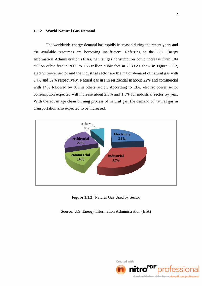
The worldwide energy demand has rapidly increased during the recent years and
the available resources are becoming insufficient. Referring to the U.S. Energy
Information Administration (EIA), natural gas consumption could increase from 104
trillion cubic feet in 2005 to 158 trillion cubic feet in 2030.As show in Figure 1.1.2,
electric power sector and the industrial sector are the major demand of natural gas with
24% and 32% respectively. Natural gas use in residential is about 22% and commercial
with 14% followed by 8% in others sector. According to EIA, electric power sector
consumption expected will increase about 2.8% and 1.5% for industrial sector by year.
With the advantage clean burning process of natural gas, the demand of natural gas in
transportation also expected to be increased.
Figure 1.1.2: Natural Gas Used by Sector
Source: U.S. Energy Information Administration (EIA)
Electricity
24%
industrial
32%
commercial
14%
residential
22%
others
8%

3
1.2 ACID GASES
Engineering standard for process design of gas treating unit defined acid gas
present in most natural gas streams mainly hydrogen sulfide and carbon dioxide.
Natural gas from the wells contains significant amounts of hydrogen sulfide and carbon
dioxide an also known as sour gas (Speight, 2007). Because of the extremely corrosive
and toxicity of sulfur compound, the acid gas should be removed and the process
removal also known as sweetening and treating process.
1.3 GAS PROCESSING PLANT (GPP)
Figure 1.3: Process flow of gas processing plant
Figure 1.3 shows the several processes involved in gas processing plant. The
processes in the gas processing plant are acid gas removal, dehydration, mercury
removal and product recovery unit which are hydrocarbons separation based on their
group. Raw gas from the offshore is transported by pipeline to the separation process to
separate between the oil, gas and water at pre-treatment unit. In the pre-treatment unit,
contaminant is removed and the clean gas is transferred to the AGRU.

4
In the AGRU, acid gas is removed and the treated gas will proceed with the
dehydration process. Dehydration is the removal of the water. It is necessary to ensure
smooth operation of gas transmission lines. Dehydration prevents the formation of gas
hydrates and reduces corrosion. The next step is mercury removal by using adsorption
processes before the gas fed into distillation in a demethanizer fractionating column.
After methane was separated, the gas is continuously processed in the product recovery
unit which consist of three distillation tower is series called a deethanizer, a
depropanizer and a debutanizer. The product from the gas processing plant enters a
compressor station where it is pressurized for transmission (Chakma, 1997). Methane is
usually transported by pipeline as commercial gases. Other group of hydrocarbon
(ethane, propane, butane) will be distributed to industry, consumers and domestic use.
1.4 ACID GAS REMOVAL UNIT (AGRU)
As show in figure 1.3, acid gas removal unit is the process after pre-treatment
unit. In the pre-treatment unit, slugs, waters and others contaminants is remove before
the gas transferred to the acid gas removal unit. Contaminants in the acid gas will
disturb the process in acid gas removal. In the acid gas removal unit, the acid gas will be
remove to meet the specification. Acid gas removal unit is the earlier process in the gas
processing plant can avoided corrosion and hydration problem when the gases undergo
others process. In the acid gas removal unit, there many process to remove acid gas.
There two general processes in removal acid gases, by absorption and adsorption
(McCain et al, 1997).
5
1.5 WHY NEED TO REMOVE ACID GAS
Acid gases, mainly hydrogen sulphide and carbon dioxide need to be removed at
specific level due to transportation and safety requirement.
1.5.1 Transportation Requirement
Natural gas main transportation is by using pipeline. Others than that, it is also
can be transported by using liquefied Natural Gas (LNG), compress natural gas (CNG),
gas to solid (GTL), gas to solid (GTS), gas to power (GTP), and gas to commodity
(GTC) (Mokhatab, S. et al., 2006).
Commonly steel is a material using as a medium transportation of natural gas.
One of common problems in the transportation of natural gas by pipeline is corrosion.
Corrosion is defined as the deterioration of material, usually metal, due to some reaction.
The corrosion can cause by water, impurities, or acid gases in the gas. H2S is extremely
corrosive gas that found in the natural gas. As the reason, this gas should be removed in
safe composition in the natural gas to avoid the corrosion problem (Bhide, et. al, 1997).
Also stated in his book as an internal corrosion protection, chemical corrosion inhibitor
can be used but it is most practically used in small scale transportation.
Removal acid gases also is a prevention of hydration in pipeline. A gas hydrate
is an ice-like crystalline solid called clathrate (Speight, 2007). The exact temperature
and pressure at which hydrate form depends on the composition of the gas and the water.
Besides that, with present of acid gas, it will increase the tendency to form hydrate. As
the pressure increase, the hydrate formation temperature also increases. Lowering the
temperature of gases also will increase the tendency of form hydration. Foaming of
hydration in pipeline will block the flow of natural gas in the pipeline.
6
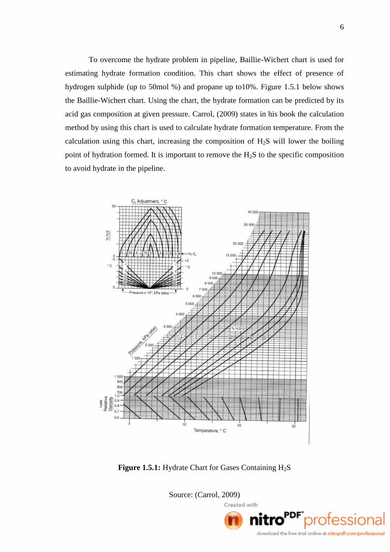
To overcome the hydrate problem in pipeline, Baillie-Wichert chart is used for
estimating hydrate formation condition. This chart shows the effect of presence of
hydrogen sulphide (up to 50mol %) and propane up to10%. Figure 1.5.1 below shows
the Baillie-Wichert chart. Using the chart, the hydrate formation can be predicted by its
acid gas composition at given pressure. Carrol, (2009) states in his book the calculation
method by using this chart is used to calculate hydrate formation temperature. From the
calculation using this chart, increasing the composition of H2S will lower the boiling
point of hydration formed. It is important to remove the H2S to the specific composition
to avoid hydrate in the pipeline.
Figure 1.5.1: Hydrate Chart for Gases Containing H2S
Source: (Carrol, 2009)

7
1.5.2 Safety Requirement
H2S is a very toxic gas and affects to human at low level of exposure. The H2S
should be remove due to safety aspect to the persons in their working area that involve
in H2S and also as a safety requirement to the consumers. Table 1.5.2 below is the level
exposure of H2S and its effect to human body
Table 1.5.2: Level exposure of H2S and its affect to the human.
Level exposure Effects
0.03 ppm Can smell and only safe for not exceed than 8 hours
exposure
4 ppm Cause eye irritation.
10 ppm Maximum exposure 10 minutes and violently with dental
mercury amalgam fillings.
20 ppm Exposure for exceed than 1 minute causes severe injury to
eye nerves.
100 ppm Respiratory paralysis in 30 to 45 minutes and will become
unconscious quickly.
200 ppm Serious eye injury and permanent damage to eye nerves and
throat.
300 ppm Loses sense of reasoning and balance. Respiratory paralysis
in 30 to 45 minutes
500 ppm Breathing problems are observed and death can be expected
in minutes.
700 ppm Permanent brain damage may result unless rescued promptly
and for more than 700ppm death will occurs immediately

8
1.6 PROCESS IN ACID GAS REMOVAL
Acid gas can be treated in many processes, Mokhatab S. et al., (2006). There are
several factor must be considered in selected the process in removal acid gas. The
factors are the types and concentration of contaminants in the feed gas, degree of
contaminant desired, the specification of acid gas, temperature, pressure, volume and
the composition of the feed gas.
Generally the process of removal acid gas used is by absorption and adsorption.
Absorption process is divided in two classes, absorption based on chemical solvent and
physical solvent. This process is depends on physical solubility and chemical reaction in
the liquid phase. Most common absorbent used in the removal acid gases process is
water, aqueous amine, caustic, and sodium carbonate. However, the solvent must be
selected by considering several factors to get the best result in the process.

9
1.6.1 Amine Process
Amine process is a one of the absorption based on chemical solvent. Depending
on the composition of the feed gas, different group of amine need to select to match the
criteria of best solvent. James G. Speight (2007), was highlighted in his book six types
of amine that usually used as solvent in the amine process. Table 1.6.1 are listing the
group of amine and its properties.
Table 1.6.1: Properties of Amine Solvent
Name Derive
Name
Mole.
weight
Specific
Gravity
Melting
Point
℃
Boiling
Point
℃
Flash
Point
℃
Relative
Capacity
%
Monoethanolamine MEA 61.08 1.01 10 170 85 100
Diethanolamine DEA 105.14 1.097 27 217 169 58
Triethanolamine TEA 148.19 1.124 18 335, d 185 41
Diglycolamine DGA 105.14 1.057 -11 223 127 58
Diisopropanolamne DIPA 133.19 0.99 42 248 127 46
Methyl-
Diethanolamine MDEA 119.17 1.03 -21 247 127 51
Source: James G. Speight (2007)

10
Figure 1.6.1: Process Flow Diagram for Amine Process
Source: W.I Echt. (1997)
Figure 1.6.1 shows the general amine process flow diagram. The feed gas will
enter at the bottom of absorber column and flows up and contacted countercurrent with
the amine solution. Treated gas which also known as sweet gas will exit at the top of
absorber column. At the bottom of absorber column, rich amine solution will exit and
go through the flash tank. In the flash tank, the hydrocarbon that may have dissolved or
condensed will be recovered. The process is continued with rich amine will regenerate
at the regenerator column. The regeneration process operates at low pressure and high
temperature. Reboiler is added at the bottom of column in order to maintain the
temperature inside the regenerator. Acid gas will separate from the amine and the acid
gas leave at the top column and go to the condenser. Lean amine from the bottom
regenerator will pumped through the lean-rich amine heat exchanger and cooler before
enters the absorber column. The process is close loop process where the solvent is
recycled (UOP, 2007).
11
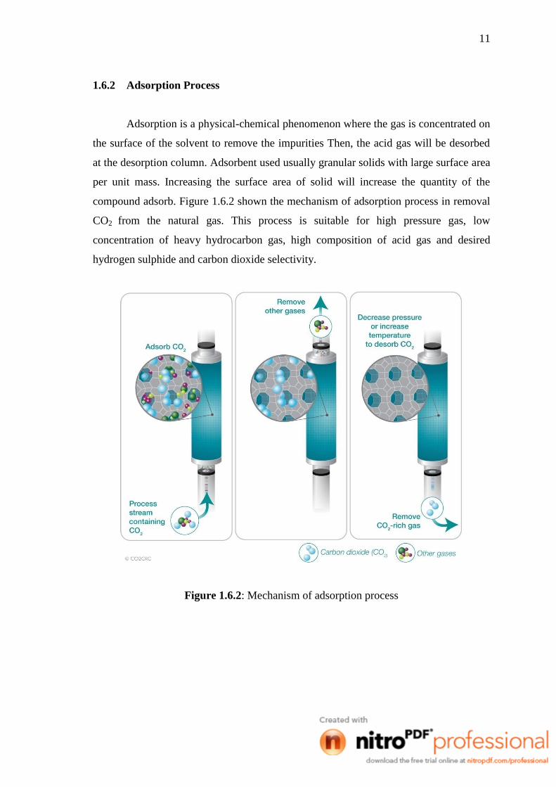
1.6.2 Adsorption Process
Adsorption is a physical-chemical phenomenon where the gas is concentrated on
the surface of the solvent to remove the impurities Then, the acid gas will be desorbed
at the desorption column. Adsorbent used usually granular solids with large surface area
per unit mass. Increasing the surface area of solid will increase the quantity of the
compound adsorb. Figure 1.6.2 shown the mechanism of adsorption process in removal
CO2 from the natural gas. This process is suitable for high pressure gas, low
concentration of heavy hydrocarbon gas, high composition of acid gas and desired
hydrogen sulphide and carbon dioxide selectivity.
Figure 1.6.2: Mechanism of adsorption process

12
1.6.3 Gas Permeation
Gas permeation is a process already applied in industry to remove the acid gas.
The advantages of this process are low methane loss in permeate, and cost effective due
to its single stage operation (Rojey et al., 1997). In this process, the acid gas separated
by using membrane which is usually polymeric or organic membranes. For a gas to
permeate through a membrane surface, the gas must first dissolve in the high pressure
side of membrane, diffuse across the membrane wall and evaporate from the low
pressure side (Ahmad et al, 2010). Figure 1.6.3 is the mechanism of the gas permeation
process.
Figure 1.6.3: Gas Permeation Mechanism
Source: Ahmad et al, (2010)

13
1.7 PROBLEM STATEMENTS
Acid gas removal in this research involves stripper column as main equipment.
Besides that, in order to complete this process others equipment such as, reboiler, flash
column, cooler, and pump is added. However, this process is highly energy
consumption to remove the acid gases. The operating cost of this process also increases
in order to supply the energy. For Benfield process, foaming of solvent is a common
problem in the absorption process. Foaming of solvent will reduce the tendency of
solvent to absorb acid gases. Thus, it will decrease the efficiency of the absorption
process overall.
1.8 RESEARCH OBJECTIVES
This research contains two main objectives. The first objective is to minimize
the energy consumption in Acid Gas Removal Unit (AGRU) in gas processing plant by
reducing number of equipment that consume energy in the process. The second
objective is to increase the efficiency of the absorption process in acid gas removal unit
by solving the foaming problem in the absorber column.
1.9 SCOPE OF RESEARCH
This research will be focusing on simulation using Aspen Hysys, which is will
be done based on the industrial Acid Gas Removal process flow sheet that use Benfield
Solution. Comparisons between AGRU which used Benfield solution with DEA as
activator and Benfield with Piperazine activator are being compared in terms of
absorption column removal efficiency. The structural modification on AGRU design
will be compared with the existing process in terms of power consumption, process duty
and capital cost.

14
1.10 RATIONAL AND SIGNIFICANCE OF RESEARCH
In this research, the new activator will increasing the efficiency of absorption
process with no foaming problem and thus increases the efficiency of absorption
process. Since typical AGRU with DEA as activator has operational problems such as
solvent losses and degradation, foaming and corrosion, the selection of solvent with
suitable activator is therefore very important. Reducing the number of equipments is a
contribution factor to reduce the energy consumption and capital investment in the
AGRU and reduce the operating cost of the process.

15
CHAPTER 2
LITERATURE REVIEW
2.1 BENFIELD PROCESS
First basic Benfield Process was developed by Benson and Field in 1950s.
Benfield process is then improved with the new technology by adding activator in the
potassium carbonate solvent to increase reaction rate of the process. Benfield Process is
applicable to the removal of H2S and CO2 from natural gas in gas processing plant. This
process also used to remove CO2 in ammonia plant and it is well known around the
world for CO2 removal for many chemical plant industries. Francais S. Manning stated
in his book, Benfied Process have three basic process flowsheet, that is single stage
absorber, split flow absorber, and two stage absorber as shown in Figure 2.1, (a),(b),(c)
respectively.
Figure 2.1(a): Single Stage Absorber