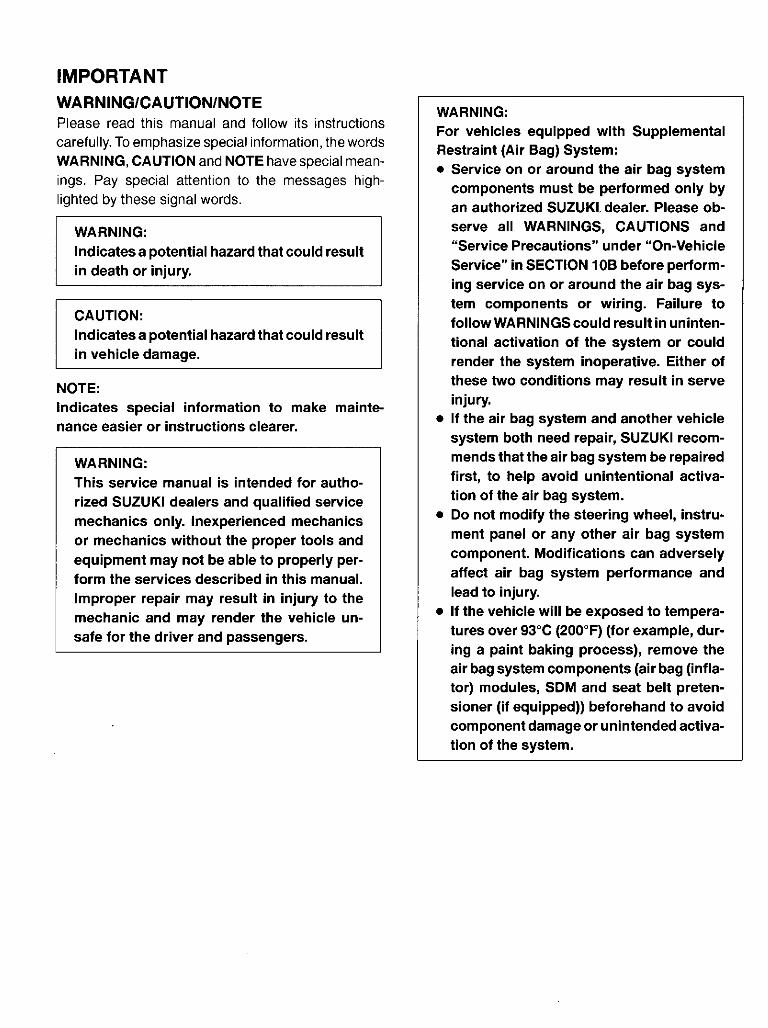
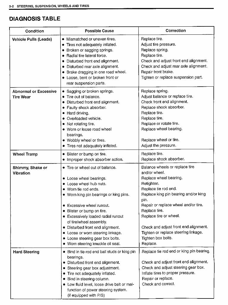
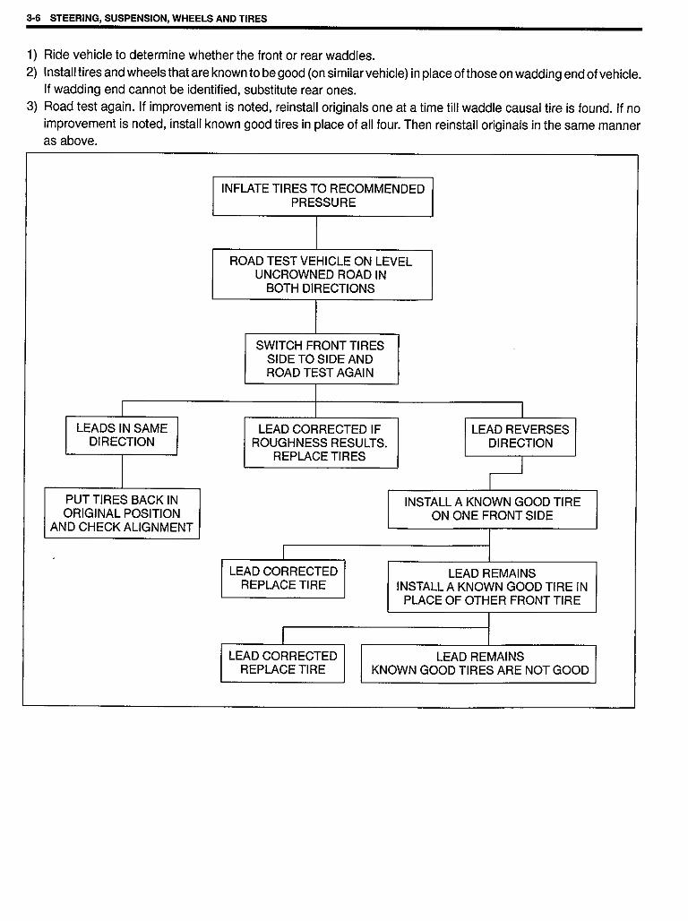
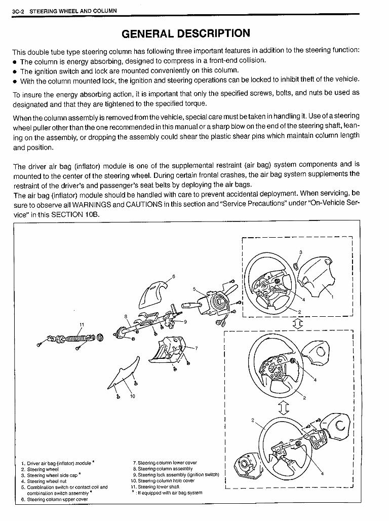
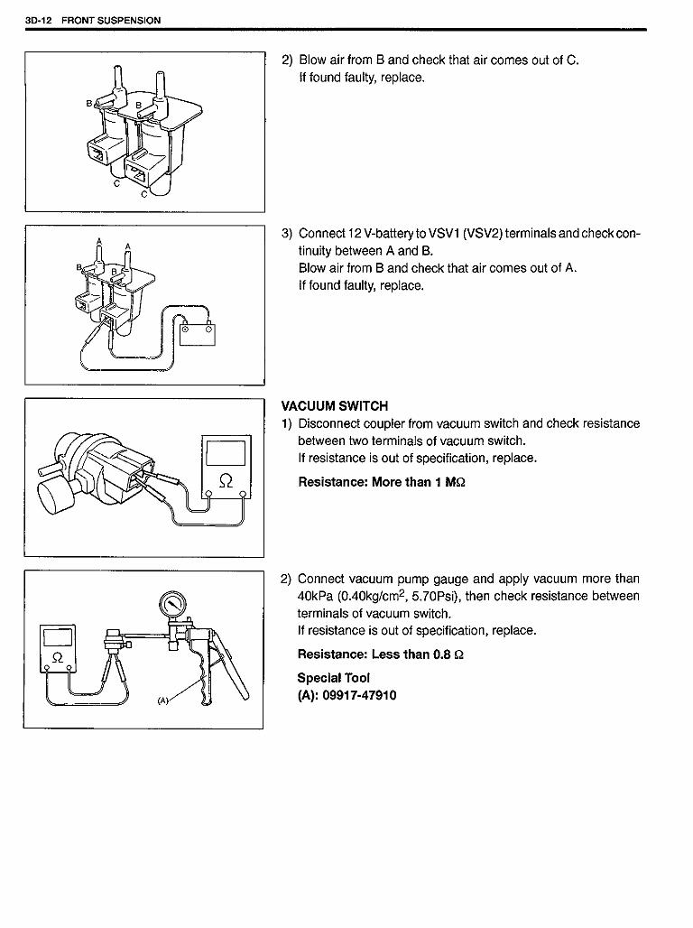
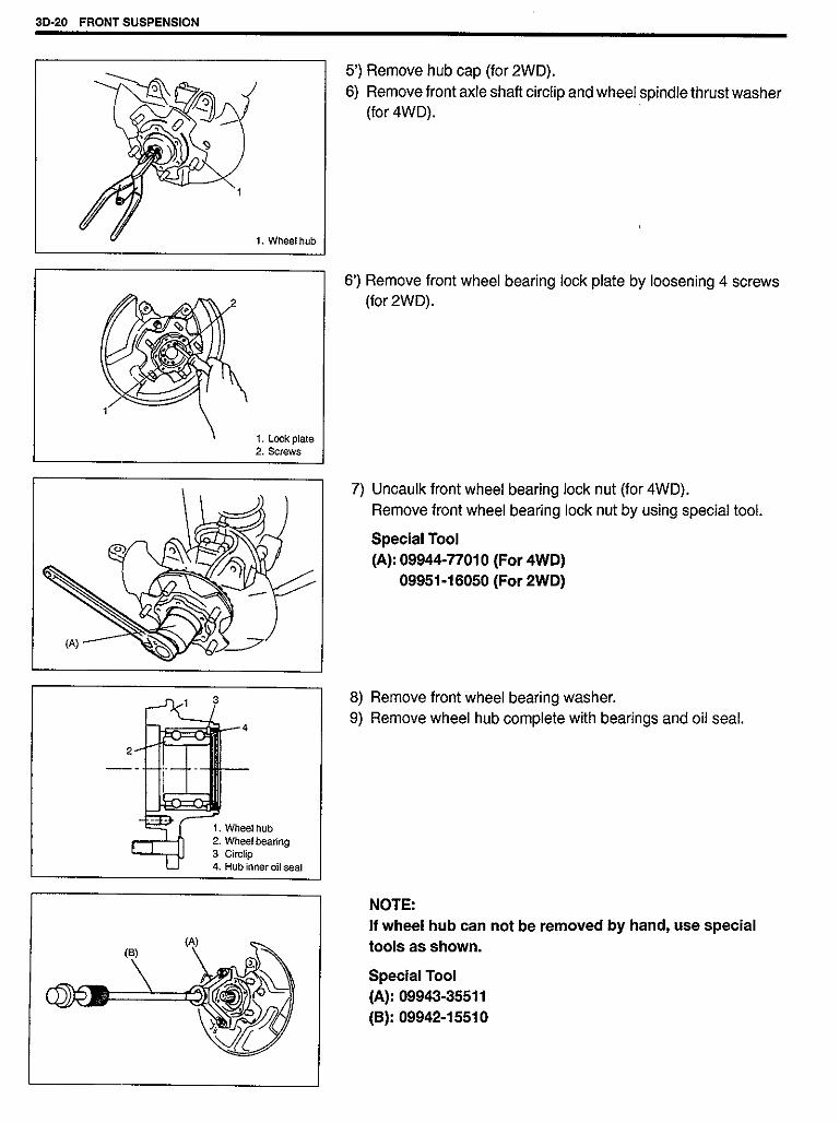
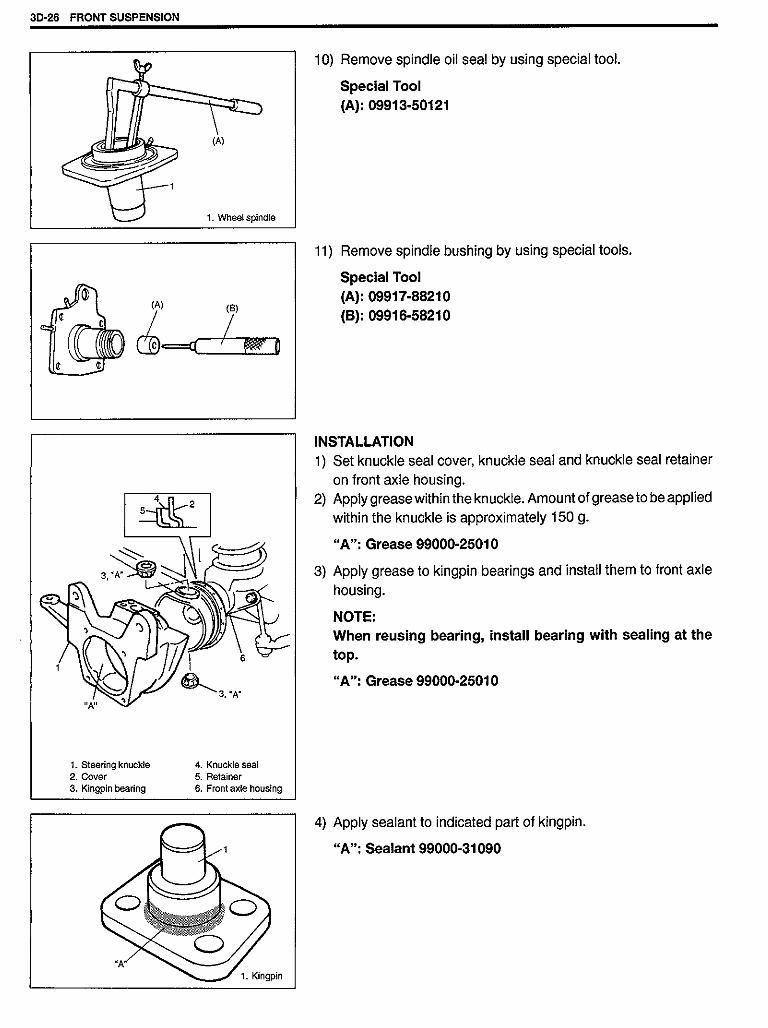
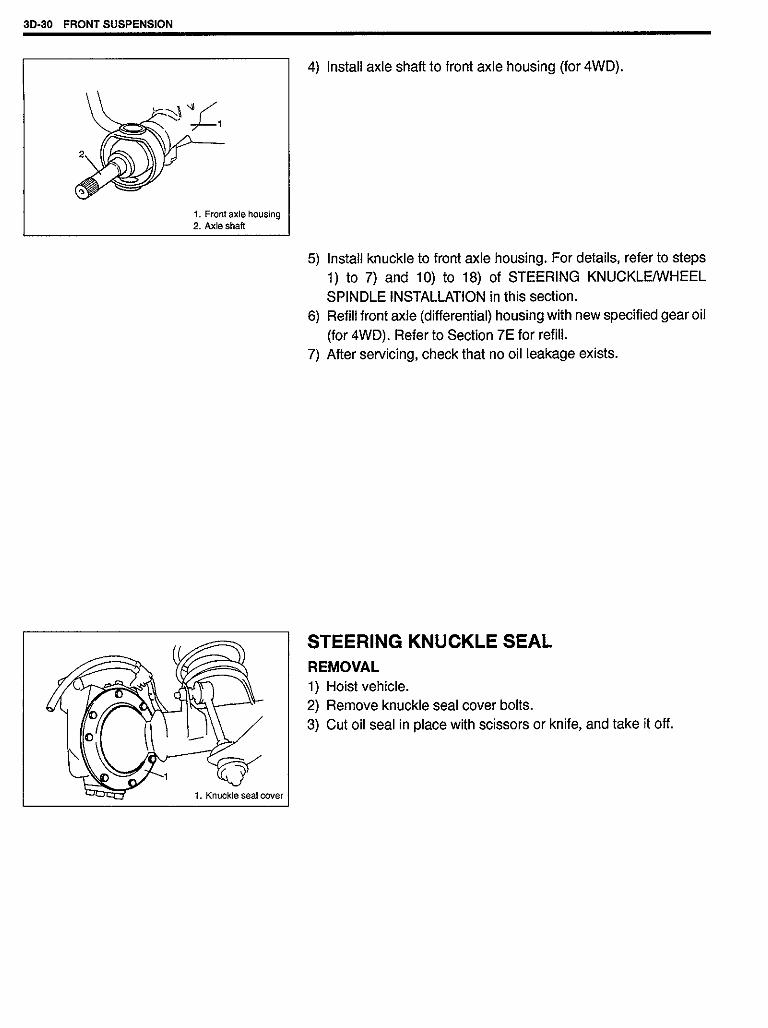
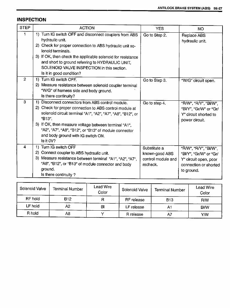
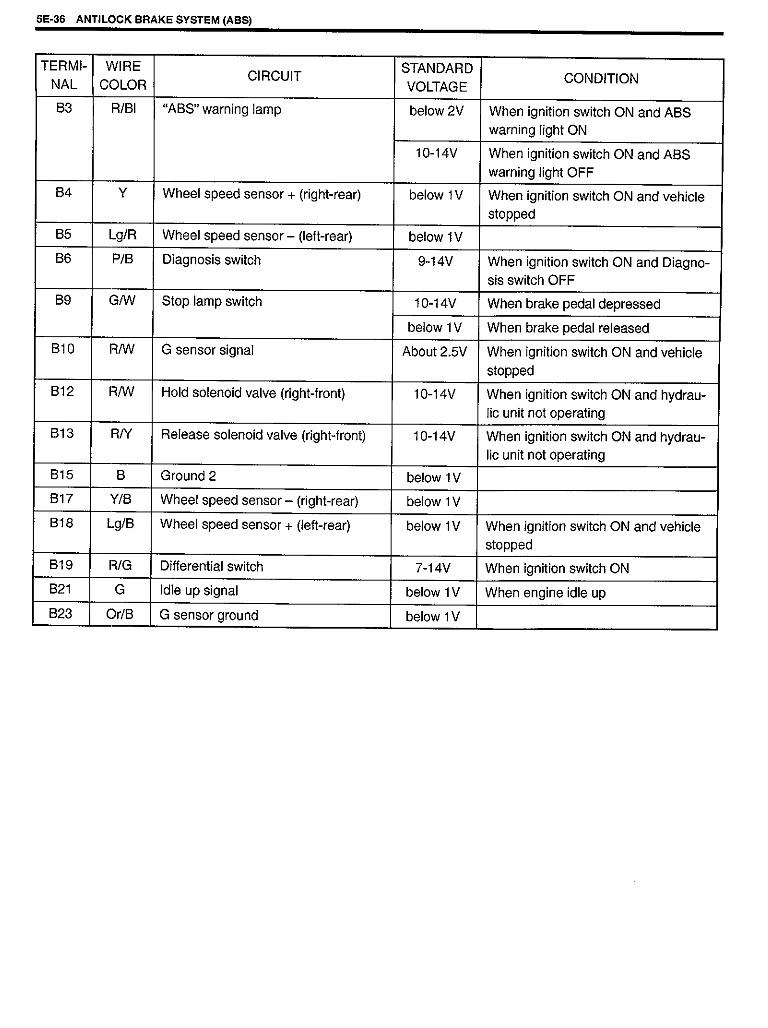
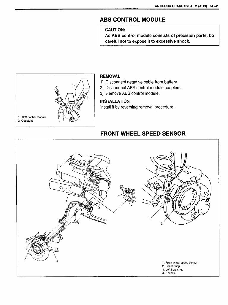
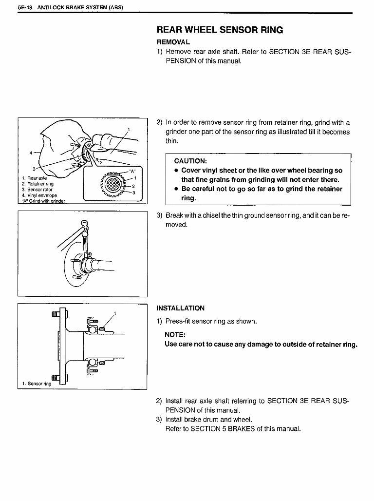
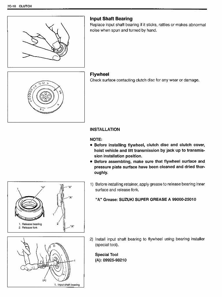
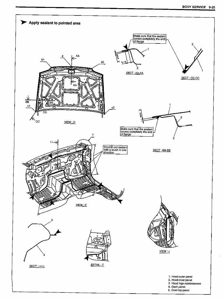
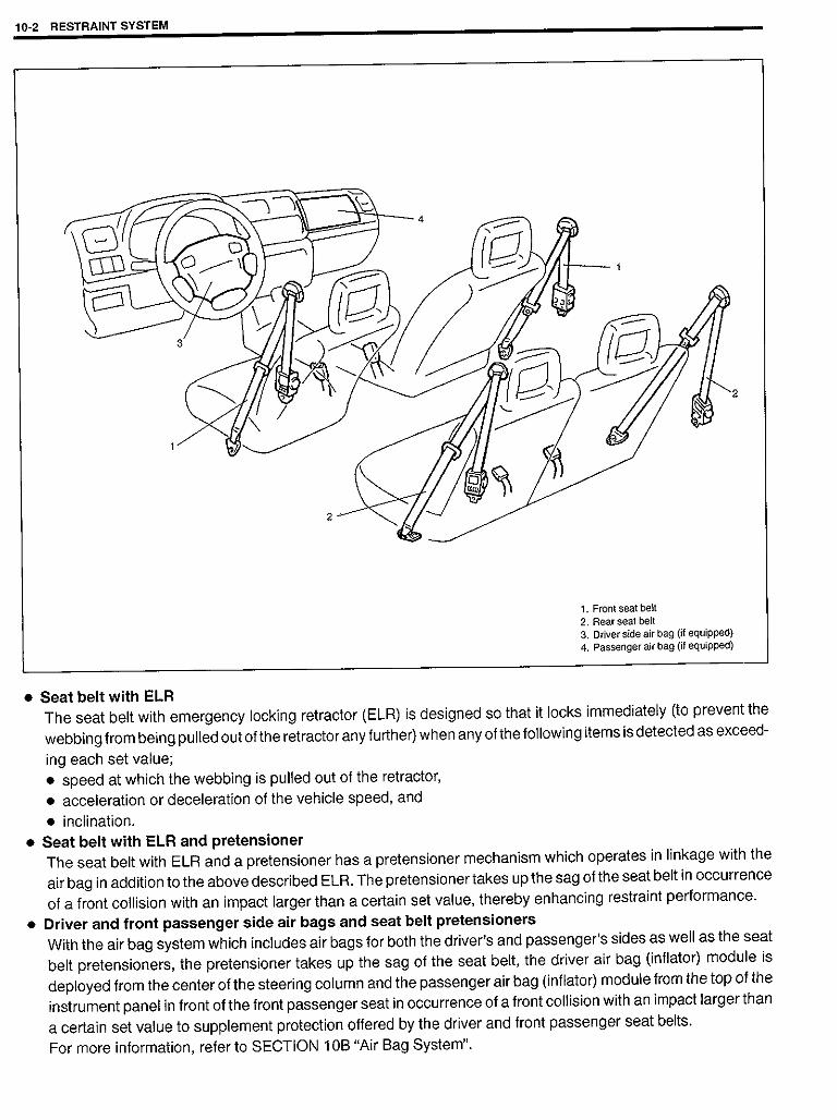
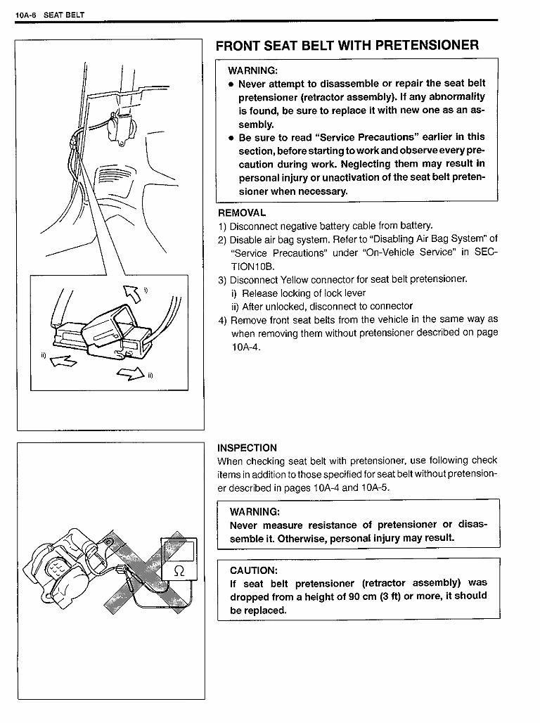
suzuki jimny,taller,2002
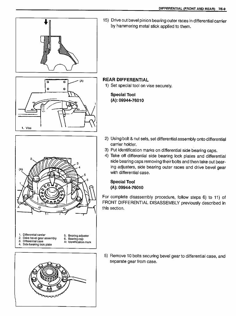
TRANSCRIPT


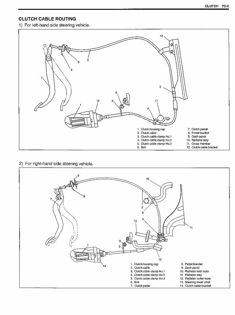
11) Apply grease to spindle bushing inside surface, flange andshaft (for 4WD) of wheel spindle.
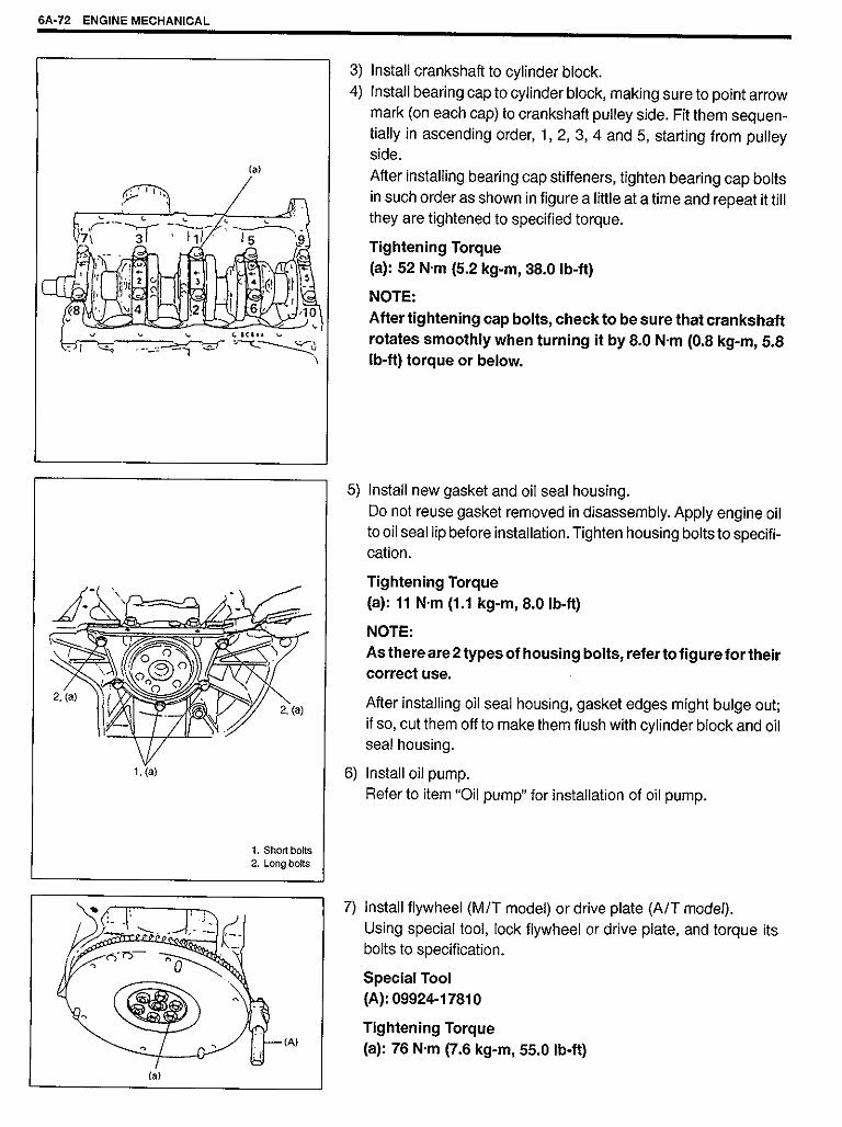
“A”: Grease 99000-25010
CAUTION:As this hole is a part of the passage of the vacuumthat activates the air locking hub, if it is clogged withgrease, the air locking hub cannot be locked or un-locked.Therefore, be careful not to apply too much greaseto avoid clogging the vacuum passage.
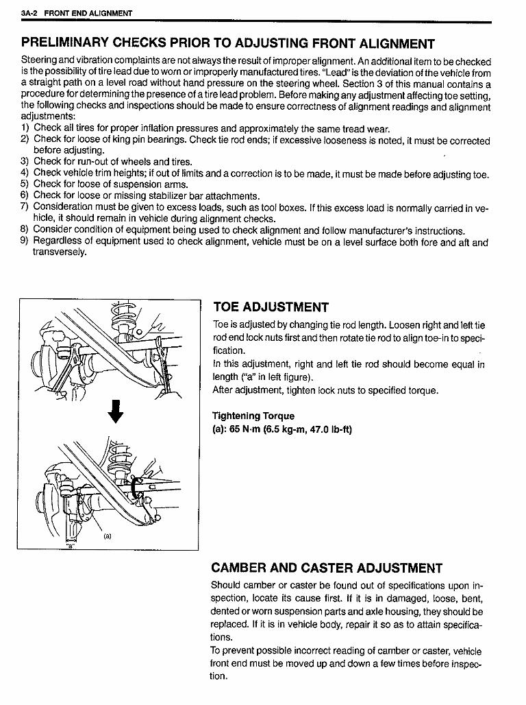
12) Install wheel spindle to knuckle, coat their mating surface withsealant.
“B”: Sealant 99000-31110 or 99000-31090
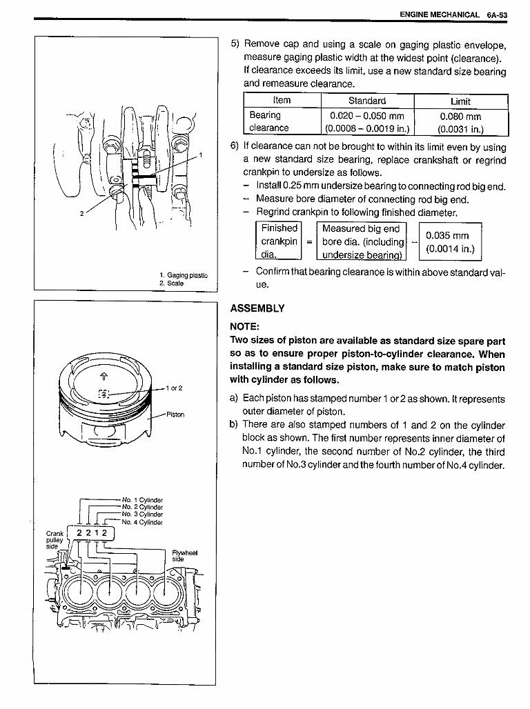
1. Wheel spindle2. Spindle bushing
13) Install wheel spindle and disc dust cover to steering knuckle.Tighten wheel spindle bolts to specified torque.
Tightening Torque(a): 50 N·m (5.0 kg-m, 36.5 lb-ft)
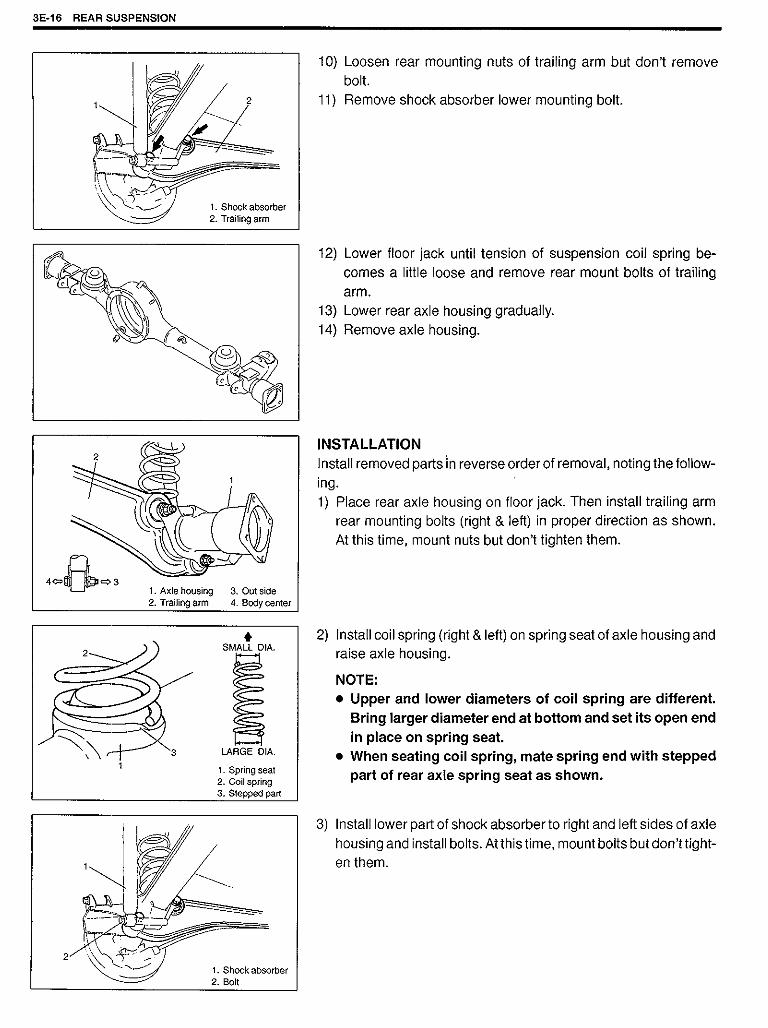
1. Wheel spindle2. Disc dust cover
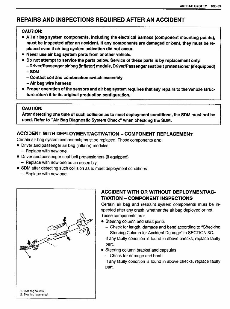
14) Blow air into pipes at the top and the front of wheel spindle andcheck that it comes out of the hole as shown in figure (for4WD).
CAUTION:As this hole is a part of the passage of the vacuumthat activates the air locking hub, if it is clogged withgrease, the air locking hub cannot be locked or un-locked.Therefore, be careful not to apply too much greaseto avoid clogging the vacuum passage.
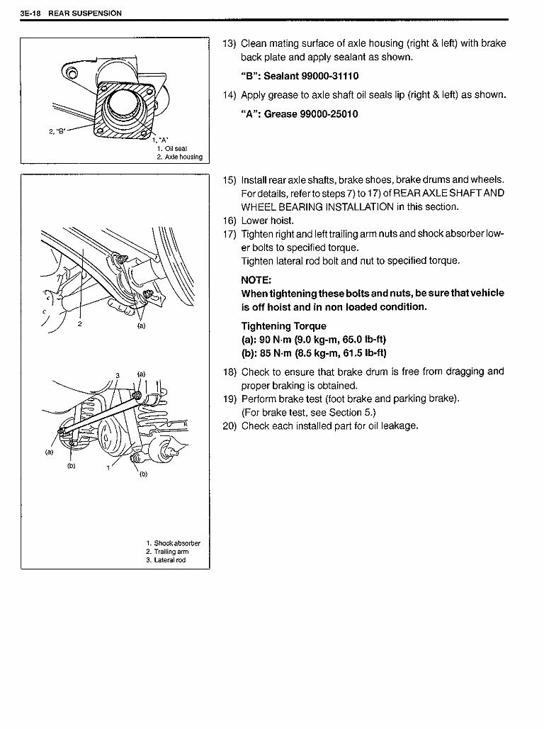
15) Connect spindle vacuum hoses to wheel spindle (for 4WD).16) Connect tie rod and drag rod to steering knuckle, refer to TIE
ROD AND DRAG ROD INSTALLATION of Section 3B.17) Install wheel hub assembly, refer to steps 5) to 16’) of WHEEL
HUB INSTALLATION in this section.18) Install wheel and tighten wheel nuts to specified torque, refer
to TIGHTENING TORQUE SPECIFICATIONS in this section.19) Lower hoist.
3D-28 FRONT SUSPENSION


PROPELLER SHAFTS 4B-1
SECTION 4B
PROPELLER SHAFTSNOTE:� All propeller shaft fasteners are an important attaching part in that it could affect the performance of vital
parts and systems, and/or could result in major repair expense. They must be replaced with one of thesame part number or with an equivalent part if replacement becomes necessary. Do not use a replace-ment part of lesser quality or substitute design. Torque values must be used as specified during reas-sembly to assure proper retention of this part.
� Never attempt to heat, quench or straighten any propeller shaft part. Replace it with a new part, or dam-age to the part may result.
CONTENTS
GENERAL DESCRIPTION 4B-1. . . . . . . . . . . . . . . . . . . . . . . . . . . . . . . . . . . . . . . . . . . . . . . . . . . . . . . . . . . . . . . . . . . . . . . . .
DIAGNOSIS 4B-2. . . . . . . . . . . . . . . . . . . . . . . . . . . . . . . . . . . . . . . . . . . . . . . . . . . . . . . . . . . . . . . . . . . . . . . . . . . . . . . . . . . . . . Diagnosis Table 4B-2. . . . . . . . . . . . . . . . . . . . . . . . . . . . . . . . . . . . . . . . . . . . . . . . . . . . . . . . . . . . . . . . . . . . . . . . . . . . . . . . . Propeller Shaft Joint Check 4B-2. . . . . . . . . . . . . . . . . . . . . . . . . . . . . . . . . . . . . . . . . . . . . . . . . . . . . . . . . . . . . . . . . . . . . .
ON-VEHICLE SERVICE 4B-3. . . . . . . . . . . . . . . . . . . . . . . . . . . . . . . . . . . . . . . . . . . . . . . . . . . . . . . . . . . . . . . . . . . . . . . . . . . Removal 4B-3. . . . . . . . . . . . . . . . . . . . . . . . . . . . . . . . . . . . . . . . . . . . . . . . . . . . . . . . . . . . . . . . . . . . . . . . . . . . . . . . . . . . . . . Installation 4B-3. . . . . . . . . . . . . . . . . . . . . . . . . . . . . . . . . . . . . . . . . . . . . . . . . . . . . . . . . . . . . . . . . . . . . . . . . . . . . . . . . . . . . Universal Joint 4B-4. . . . . . . . . . . . . . . . . . . . . . . . . . . . . . . . . . . . . . . . . . . . . . . . . . . . . . . . . . . . . . . . . . . . . . . . . . . . . . . . . .
TIGHTENING TORQUE SPECIFICATION 4B-6. . . . . . . . . . . . . . . . . . . . . . . . . . . . . . . . . . . . . . . . . . . . . . . . . . . . . . . . . . . .
REQUIRED SERVICE MATERIAL 4B-6. . . . . . . . . . . . . . . . . . . . . . . . . . . . . . . . . . . . . . . . . . . . . . . . . . . . . . . . . . . . . . . . . .
SPECIAL TOOL 4B-6. . . . . . . . . . . . . . . . . . . . . . . . . . . . . . . . . . . . . . . . . . . . . . . . . . . . . . . . . . . . . . . . . . . . . . . . . . . . . . . . . .
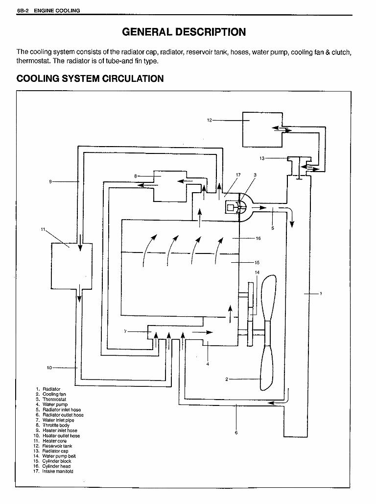
GENERAL DESCRIPTION
1. Propeller shaft No. 12. Propeller shaft No. 23. Propeller shaft No. 3
Tightening Torque(a): 50 N·m (5.0kg-m, 36.5lb-ft)(b): 33 N·m (3.3kg-m, 24lb-ft)
4B


� Grease splines of propeller shaft No. 2 and No. 3.
“A”: Chassis Grease 99000-25030
� Match marks are provided on slip-on spline connections of pro-peller shaft No. 2 and No. 3. Inserting splined end into spIinedbore without regard to match marks can be a possible cause ofnoise or vibration of propeller shaft. Be sure to index marks.
1. Match mark
UNIVERSAL JOINTDISASSEMBLY1) Using special tool, remove 4 circlips.
Special tool(A): 09900-06108
1. Circlip
2) Apply penetrate lubricant between bearing race outer diameterand shaft yoke bore.
3) Using a set of special tool, push spider bearing race out 3 – 4mm (0.12 – 0.16 in.) from shaft yoke side face.
Special tool(B): 09926-48010
Pushed out value of bearing race from shaft yoke side face“a”: 3 – 4 mm (0.12 – 0.16 in.)
1. Spider bearing race2. Shaft yoke side face
4B-4 PROPELLER SHAFTS

4) Tapping shaft yoke with a hammer, remove bearing race fromshaft yoke completely.
5) Take out bearing race on the opposite side of shaft yoke in thesame way as shown above.
1. Bearing race2. Shaft yoke
6) Push out bearing race on flange yoke in the same way as Step2).
7) Holding bearing race by a vise, tap flange yoke and take outrace.
8) Take out bearing race on the opposite side of flange yoke in thesame way as Step 5) to Step 6).
1. Flange yoke2. Bearing race3. Vise
REASSEMBLY
1. Spider2. Bearing
CAUTION:Do not reuse spider, bearings and circlips. Otherwise itmay damage propeller shaft or cause abnormal vibrationor noise.
1) Apply grease to rollers in bearing races.
“A”: Grease 99000-25030
NOTE:Make sure that rollers in bearing race are all in place.
1. Bearing roller2. Bearing race
2) With spider inserted into bearing race to prevent rollers in racefrom coming out, insert bearing race into shaft yoke until it isflush with side face of shaft yoke, tapping it by a copper hammer.
1. Copper hammer2. Bearing race3. Shaft yoke4. Spider
PROPELLER SHAFTS 4B-5

3) Insert bearing race into opposite side of shaft yoke until it is flushwith side face of shaft yoke, tapping it by a copper hammer.
4) In the same way as Step 2) to Step 3), insert bearing races intoflange yoke.
5) Using round bar of 22 – 24 mm (0.87 in. – 0.94 in.) in diameterand hammer, tap bearing races into shaft or flange yoke until cir-clips can be installed in its groove on yoke bores.
6) Install 4 circlips in each groove on shaft and flange yoke bores.
NOTE:� After reassembly, ensure that both shaft yoke and flange
yoke move smoothly.� Make sure that each circlip is fitted in groove securely.
4B-6 PROPELLER SHAFTS
TIGHTENING TORQUE SPECIFICATION
FastenerTightening torque
FastenerN·m kg-m lb-ft
Propeller shaft bolt (propeller shaft No.1 No.2 and No.3 reardifferential side)
50 5.0 36.5
Propeller shaft bolt (propeller shaft No.3 transfer case side) 33 3.3 24
REQUIRED SERVICE MATERIAL
MATERIALRECOMMENDED
SUZUKI PRODUCTUSE
Lithium greaseSUPER GREASE C(99000-25030)
To apply to spider bearing race.
SPECIAL TOOL
09900-06108Snap ring pliers (Closing type)
09926-48010Universal joint disassemblingtool set


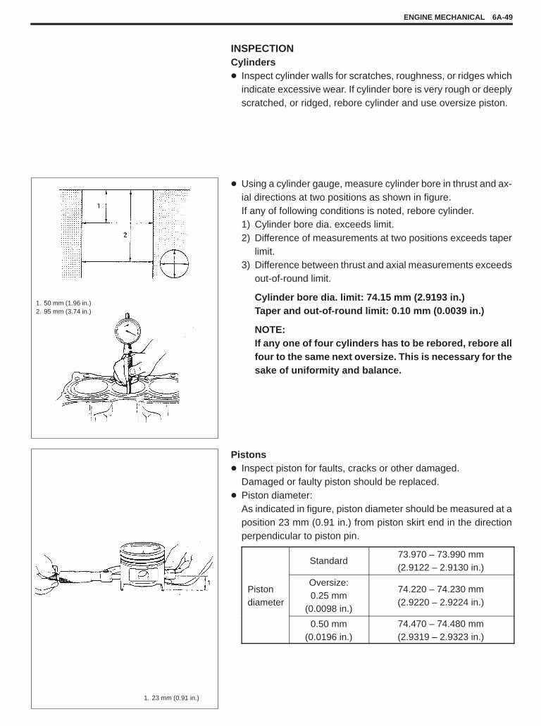
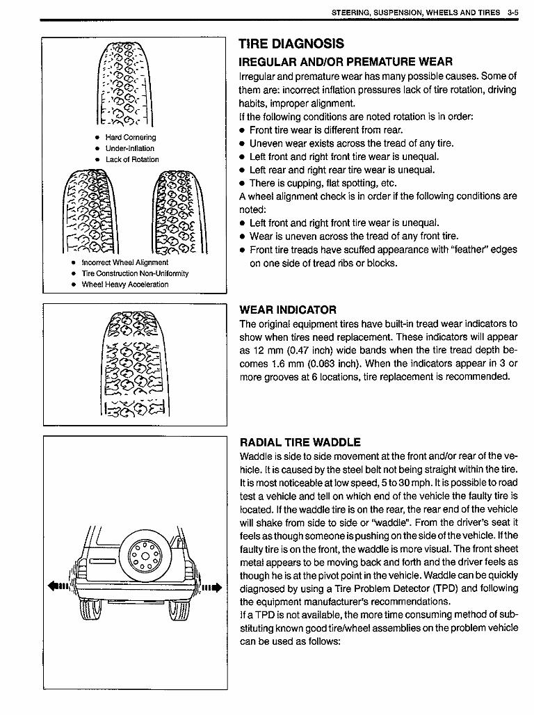
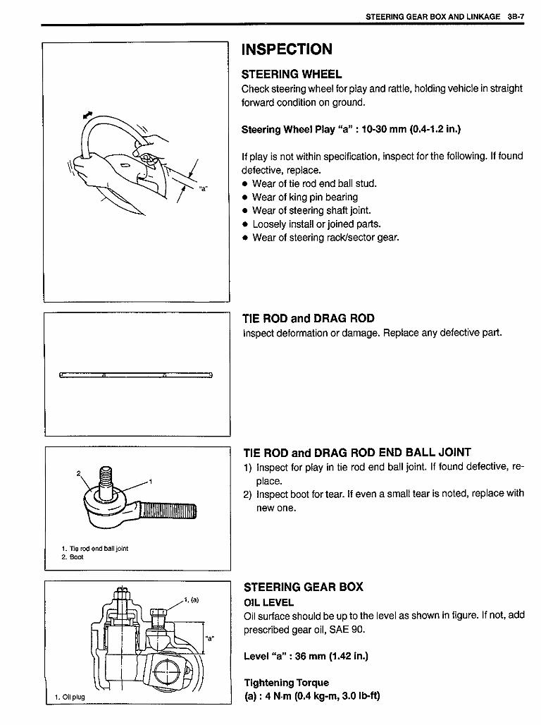
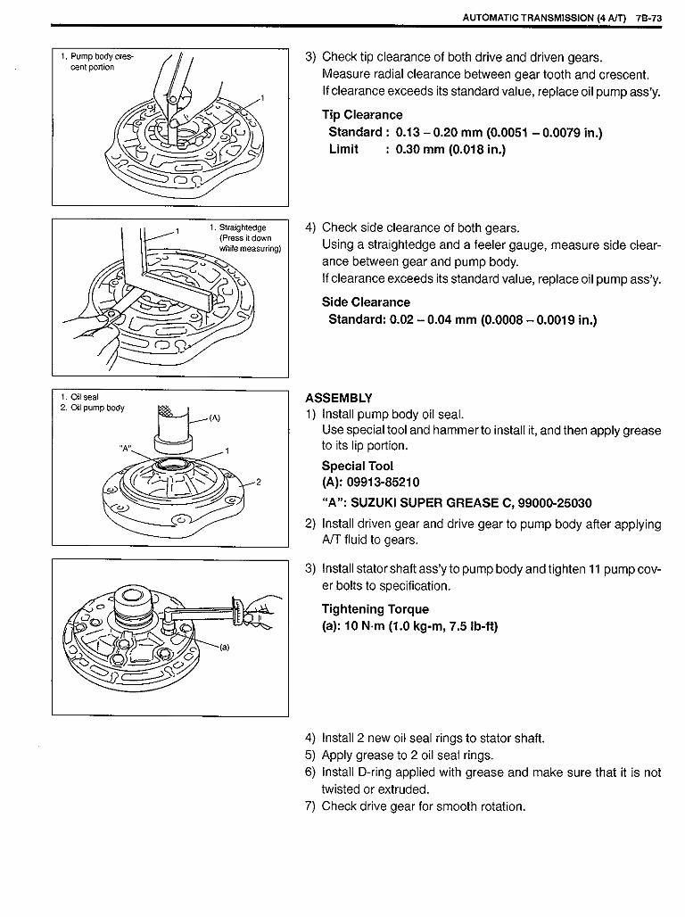
INSPECTIONCylinders� Inspect cylinder walls for scratches, roughness, or ridges which
indicate excessive wear. If cylinder bore is very rough or deeplyscratched, or ridged, rebore cylinder and use oversize piston.
� Using a cylinder gauge, measure cylinder bore in thrust and ax-ial directions at two positions as shown in figure.If any of following conditions is noted, rebore cylinder.1) Cylinder bore dia. exceeds limit.2) Difference of measurements at two positions exceeds taper
limit.3) Difference between thrust and axial measurements exceeds
out-of-round limit.
Cylinder bore dia. limit: 74.15 mm (2.9193 in.)Taper and out-of-round limit: 0.10 mm (0.0039 in.)
NOTE:If any one of four cylinders has to be rebored, rebore allfour to the same next oversize. This is necessary for thesake of uniformity and balance.
1. 50 mm (1.96 in.)2. 95 mm (3.74 in.)
Pistons� Inspect piston for faults, cracks or other damaged.
Damaged or faulty piston should be replaced.� Piston diameter:
As indicated in figure, piston diameter should be measured at aposition 23 mm (0.91 in.) from piston skirt end in the directionperpendicular to piston pin.
1. 23 mm (0.91 in.)
ENGINE MECHANICAL 6A-49
Standard73.970 – 73.990 mm(2.9122 – 2.9130 in.)
Pistondiameter
Oversize:0.25 mm
(0.0098 in.)
74.220 – 74.230 mm(2.9220 – 2.9224 in.)
0.50 mm(0.0196 in.)
74.470 – 74.480 mm(2.9319 – 2.9323 in.)


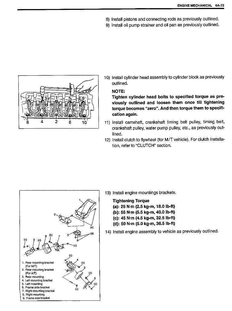


4) Hoist vehicle and drain transmission oil.5) Remove exhaust No.1 pipe, refer to Section 6K.6) Remove propeller shaft No.1 (and No.2, if equipped for 4WD),
refer to Section 4B.7) Remove gear shift control joint bolt and extension rod bolt.8) Apply transmission jack and remove rear mounting bracket with
gear shift case mounting bracket and engine rear mounting.9) Remove rear gear shift control assembly.
1. Gear shift control joint2. Extension rod3. Rear mounting bracket4. Gear shift case mounting bracket5. Engine rear mounting6. Rear gear shift control assembly
INSPECTION� Check that gear shift control lever moves smoothly without ab-
normal noise.� Check bushes and boot for damage and deterioration.
INSTALLATIONInstall in reverse order of removal procedure noting followingpoints.
“A”: Grease 99000-25010“B”: Sealant 99000-31110“C”: Thread lock 99000-32020
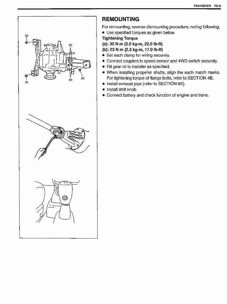
� Press fit oil seal, referring to figure for installing direction.� Make breather of boot face downward as shown in figure.� Torque bolts to specifications, as given below.
Tightening Torque(a): 23 N·m (2.3 kg-m, 17.0 lb-ft)(b): 25 N·m (2.5 kg-m, 18.0 lb-ft)(c): 18 N·m (1.8 kg-m, 13.0 lb-ft)(d): 50 N·m (5.0 kg-m, 36.5 lb-ft)(e): 5.5 N·m (0.55 kg-m, 4.0 lb-ft)(f): 18 N·m (1.8 kg-m, 13.0 lb-ft) (For 6 mm bolt) 34 N·m (3.4 kg-m, 24.5 lb-ft) (For 8 mm bolt)
NOTE:Do not reuse for gear shift rear arm bolt whose size is 6 mm.
� When installing propeller shaft(s), refer to Section 4B.� When installing exhaust No.1 pipe, refer to Section 6K.� After connect clutch cable, adjust clutch pedal free travel, refer
to Section 7C.
1. Gear shift knob2. Gear shift lever3. Gear shift lever boot
ass’y4. Gear shift lever boot No.25. Gear shift lever boot No.36. Gear shift lever boot cov-
er7. Gear shift lever plate8. Gear shift control lower
seat bolt9. Gear control select bolt
10. Gear shift lever case11. Gear shift rear shaft12. Extension rod13. Rear mounting brack-
et14. Gear shift case
mounting bracket15. Engine rear mounting16. Oil seal17. Boot18. Gear shift rear arm
bolt
7A-6 MANUAL TRANSMISSION


AUTOMATIC TRANSMISSION (4 A/T) 7B-1
SECTION 7B
AUTOMATIC TRANSMISSION (4 A/T)WARNING:For vehicles equipped with Supplemental Restraint (Air Bag) System� Service on and around the air bag system components or wiring must be performed only by an
authorized SUZUKI dealer. Refer to “Air Bag System Components and Wiring Location View” un-der “General Description” in air bag system section in order to confirm whether you are perform-ing service on or near the air bag system components or wiring. Please observe all WARNINGSand “Service Precautions” under “On-Vehicle Service” in air bag system section before perform-ing service on or around the air bag system components or wiring. Failure to follow WARNINGScould result in unintentional activation of the system or could render the system inoperative. Ei-ther of these two conditions may result in severe injury.
� Technical service work must be started at least 90 seconds after the ignition switch is turned tothe “LOCK” position and the negative cable is disconnected from the battery. Otherwise, the sys-tem may be activated by reserve energy in the Sensing and Diagnostic Module (SDM).
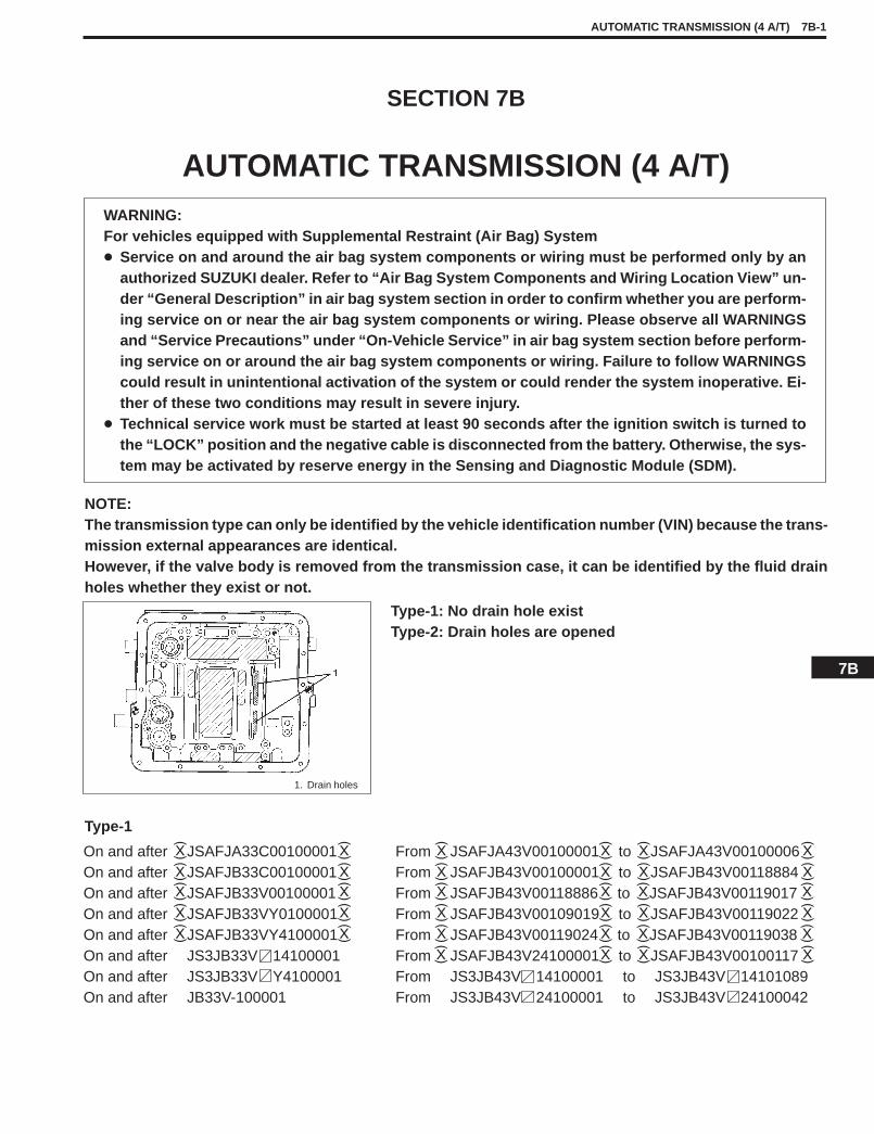
NOTE:The transmission type can only be identified by the vehicle identification number (VIN) because the trans-mission external appearances are identical.However, if the valve body is removed from the transmission case, it can be identified by the fluid drainholes whether they exist or not.
Type-1: No drain hole existType-2: Drain holes are opened
1. Drain holes
Type-1
On and after JSAFJA33C00100001On and after JSAFJB33C00100001On and after JSAFJB33V00100001On and after JSAFJB33VY0100001On and after JSAFJB33VY4100001On and after JS3JB33V 14100001On and after JS3JB33V Y4100001On and after JB33V-100001
From JSAFJA43V00100001 to JSAFJA43V00100006From JSAFJB43V00100001 to JSAFJB43V00118884From JSAFJB43V00118886 to JSAFJB43V00119017From JSAFJB43V00109019 to JSAFJB43V00119022From JSAFJB43V00119024 to JSAFJB43V00119038From JSAFJB43V24100001 to JSAFJB43V00100117From JS3JB43V 14100001 to JS3JB43V 14101089From JS3JB43V 24100001 to JS3JB43V 24100042
7B
7B-2 AUTOMATIC TRANSMISSION (4 A/T)
Type-2
On and after JSAFJA43V00100007JSAFJB43V00118885JSAFJB43V00119018JSAFJB43V00119023
On and after JSAFJB43V00119039
On and after JSAFJB43V20100001On and after JSAFJB43V24100118On and after JS3JB43V 14101090On and after JS3JB43V 24100043
CONTENTSGENERAL DESCRIPTION 7B- 3. . . . . . . . . . . . . .
ELECTRONIC SHIFT CONTROLSYSTEM 7B- 7. . . . . . . . . . . . . . . . . . . . . . . . . .
DIAGNOSIS 7B-14. . . . . . . . . . . . . . . . . . . . . . . . . . . Trouble Diagnosis Table 7B-18. . . . . . . . . . . . . . Stall Test 7B-20. . . . . . . . . . . . . . . . . . . . . . . . . . . . Time Lag Test 7B-21. . . . . . . . . . . . . . . . . . . . . . . Line Pressure Test 7B-21. . . . . . . . . . . . . . . . . . . Engine Brake Test 7B-22. . . . . . . . . . . . . . . . . . . “P” Range Test 7B-23. . . . . . . . . . . . . . . . . . . . . .
ELECTRONIC CONTROL SYSTEMDIAGNOSIS 7B-24. . . . . . . . . . . . . . . . . . . . . . . . . .
Precautions in Diagnosing Troubles 7B-24. . . . Diagnostic Trouble Code(s) Check 7B-25. . . . . How to Clear Diagnostic Trouble
Code(s) (DTC) 7B-27. . . . . . . . . . . . . . . . . . . . . . . . Diagnostic Trouble (DTC) Code Table 7B-28. . . . . TCM Power and Ground Circuit Check 7B-29. . . . . DTC 14 Turbine Rev. Sensor Signal 7B-30. . . . . . . DTC 18 Turbine Rev. Sensor, A/T VSS
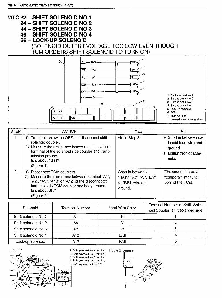
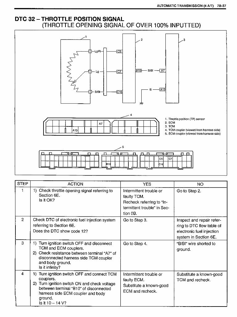
or A/T Itself 7B-31. . . . . . . . . . . . . . . . . . . . . DTC 21 Shift Solenoid No. 1 7B-32. . . . . . . . . . . . . . DTC 23 Shift Solenoid No. 2 7B-32. . . . . . . . . . . . . . DTC 43 Shift Solenoid No. 3 7B-32. . . . . . . . . . . . . . DTC 45 Shift Solenoid No. 4 7B-32. . . . . . . . . . . . . . DTC 25 Lock-up Solenoid 7B-32. . . . . . . . . . . . . . . . DTC 22 Shift Solenoid No. 1 7B-34. . . . . . . . . . . . . . DTC 24 Shift Solenoid No. 2 7B-34. . . . . . . . . . . . . . DTC 44 Shift Solenoid No. 3 7B-34. . . . . . . . . . . . . . DTC 46 Shift Solenoid No. 4 7B-34. . . . . . . . . . . . . . DTC 26 Lock-up Solenoid 7B-34. . . . . . . . . . . . . . . . DTC 31 A/T VSS 7B-35. . . . . . . . . . . . . . . . . . . . . . . . DTC 32 Throttle Position Signal 7B-37. . . . . . . . . . . DTC 33 Throttle Position Signal 7B-38. . . . . . . . . . . DTC 34 Shift Switch 7B-39. . . . . . . . . . . . . . . . . . . . . DTC 35 Engine Rev. Signal 7B-41. . . . . . . . . . . . . . DTC 36 A/T Fluid Temperature Sensor 7B-42. . . . . DTC 52 Power Source Relay in TCM 7B-44. . . . . . Inspection of TCM and Its Circuits 7B-45. . . . . . . . .
ON-VEHICLE SERVICE 7B-47. . . . . . . . . . . . . . . . . . . MAINTENANCE SERVICE 7B-47. . . . . . . . . . . . . . .
Fluid Level 7B-47. . . . . . . . . . . . . . . . . . . . . . . . . . . Fluid Change Intervals 7B-48. . . . . . . . . . . . . . . . Changing Fluid 7B-48. . . . . . . . . . . . . . . . . . . . . . . Oil Cooler Hoses 7B-48. . . . . . . . . . . . . . . . . . . . .
SELECTOR LEVER 7B-49. . . . . . . . . . . . . . . . . . . . . SHIFT SWITCH 7B-50. . . . . . . . . . . . . . . . . . . . . . . . SELECTOR ROD 7B-52. . . . . . . . . . . . . . . . . . . . . . . A/T VSS 7B-53. . . . . . . . . . . . . . . . . . . . . . . . . . . . . . . TURBINE REV. SENSOR 7B-54. . . . . . . . . . . . . . . . VSS 7B-54. . . . . . . . . . . . . . . . . . . . . . . . . . . . . . . . . . . THROTTLE POSITION SENSOR 7B- 54. . . . . . . . ECT SENSOR 7B- 54. . . . . . . . . . . . . . . . . . . . . . . . . O/D CUT SWITCH 7B- 55. . . . . . . . . . . . . . . . . . . . . SHIFT SOLENOID VALVES AND LOCK-UP
SOLENOID VALVE 7B- 56. . . . . . . . . . . . . . . . . . . . A/T FLUID TEMP. SENSOR 7B- 56. . . . . . . . . . . . . EXTENSION CASE OIL SEAL 7B- 57. . . . . . . . . . . TCM 7B- 58. . . . . . . . . . . . . . . . . . . . . . . . . . . . . . . . .
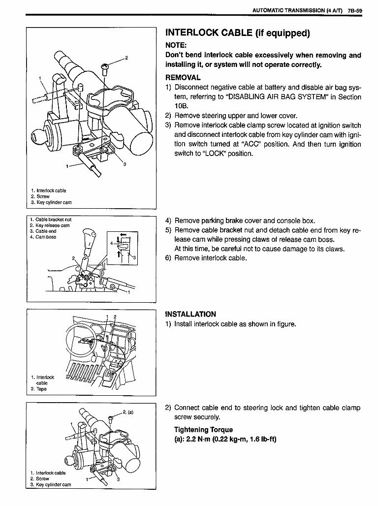
Learning Control Memory Initialization 7B- 58. . INTERLOCK CABLE (if equipped) 7B- 59. . . . . . .
TRANSMISSION UNIT REPAIROVERHAUL 7B- 61. . . . . . . . . . . . . . . . . . . . . . . . . . . .
DISMOUNTING 7B- 61. . . . . . . . . . . . . . . . . . . . . . . REMOUNTING 7B- 62. . . . . . . . . . . . . . . . . . . . . . . . DISASSEMBLY 7B- 63. . . . . . . . . . . . . . . . . . . . . . . . DISASSEMBLY OF SUBASSEMBLY 7B- 71. . . . .
Oil Pump 7B- 72. . . . . . . . . . . . . . . . . . . . . . . . . . . Front Clutch 7B- 74. . . . . . . . . . . . . . . . . . . . . . . . . Rear Clutch 7B- 79. . . . . . . . . . . . . . . . . . . . . . . . . Planetary Set 7B- 84. . . . . . . . . . . . . . . . . . . . . . . Valve Body 7B- 86. . . . . . . . . . . . . . . . . . . . . . . . . Output Shaft Assembly 7B- 91. . . . . . . . . . . . . . .
UNIT ASSEMBLY 7B- 92. . . . . . . . . . . . . . . . . . . . . .
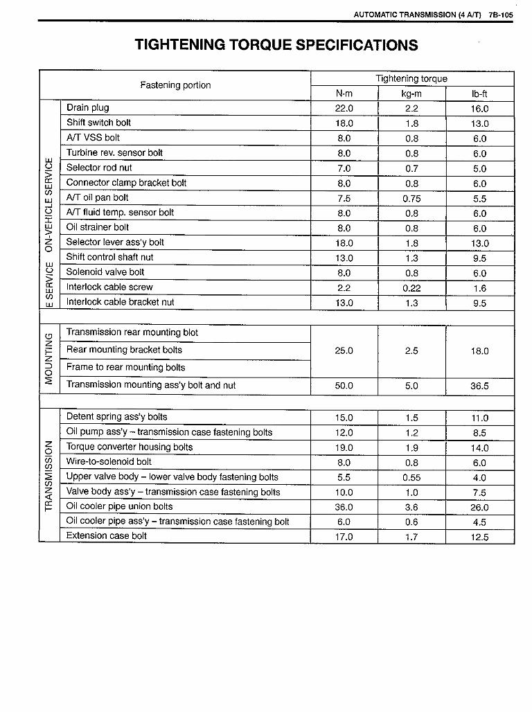
TIGHTENING TORQUE SPECIFICATIONS 7B-105.
SPECIAL TOOLS 7B-106. . . . . . . . . . . . . . . . . . . . . . . .
REQUIRED SERVICE MATERIALS 7B-107. . . . . . . .


ELECTRONIC CONTROL SYSTEMDIAGNOSIS
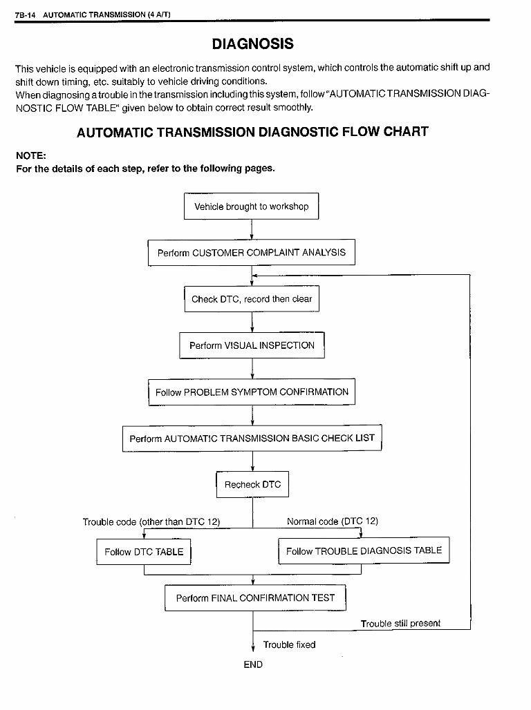
TCM has on-board diagnostic system (a system self-diagnosisfunction).Investigate where the trouble is by referring to “DIAGNOSTICFLOW TABLE” and ”DIAGNOSTIC TROUBLE CODE TABLE” onlater pages.
PRECAUTIONS IN DIAGNOSING TROUBLES[PRECAUTIONS IN IDENTIFYING DIAGNOSTIC TROUBLECODE]� Before identifying diagnostic trouble code indicated by “O/D
OFF” light, don’t disconnect couplers from TCM, battery cablefrom battery, TCM ground wire harness from engine. Such dis-connection will erase memorized trouble in TCM memory.
� The DTC stored in the TCM memory is output by flashing of “O/DOFF” light with the diagnosis switch terminal grounded.
� If no DTC is stored in the TCM memory, Code 12 is output re-peatedly.
� If DTCs are stored in the TCM memory, they are output afterCode 12 output starting from the smallest code number in the in-creasing order. After all DTCs are output, Code 12 is outputagain and so are DTCs.
� When replacing TCM with used one, learning control memory inTCM should be initialized after the replacement referring to“LEARNING CONTROL MEMORY INITIALIZATION” in thissection.
1. Data link connector (DLC)
[INTERMITTENT TROUBLES] and [NOTES ON SYSTEM CIR-CUIT INSPECTION]Refer to SECTION 0A.
7B-24 AUTOMATIC TRANSMISSION (4 A/T)


O/D CUT SWITCHINSPECTION1) Remove console box.2) Disconnect O/D cut switch coupler.3) Check continuity between O/D cut switch terminals.
1. O/D cut switch2. Shift lever
O/D cut switch ON
O/D cut switch OFF
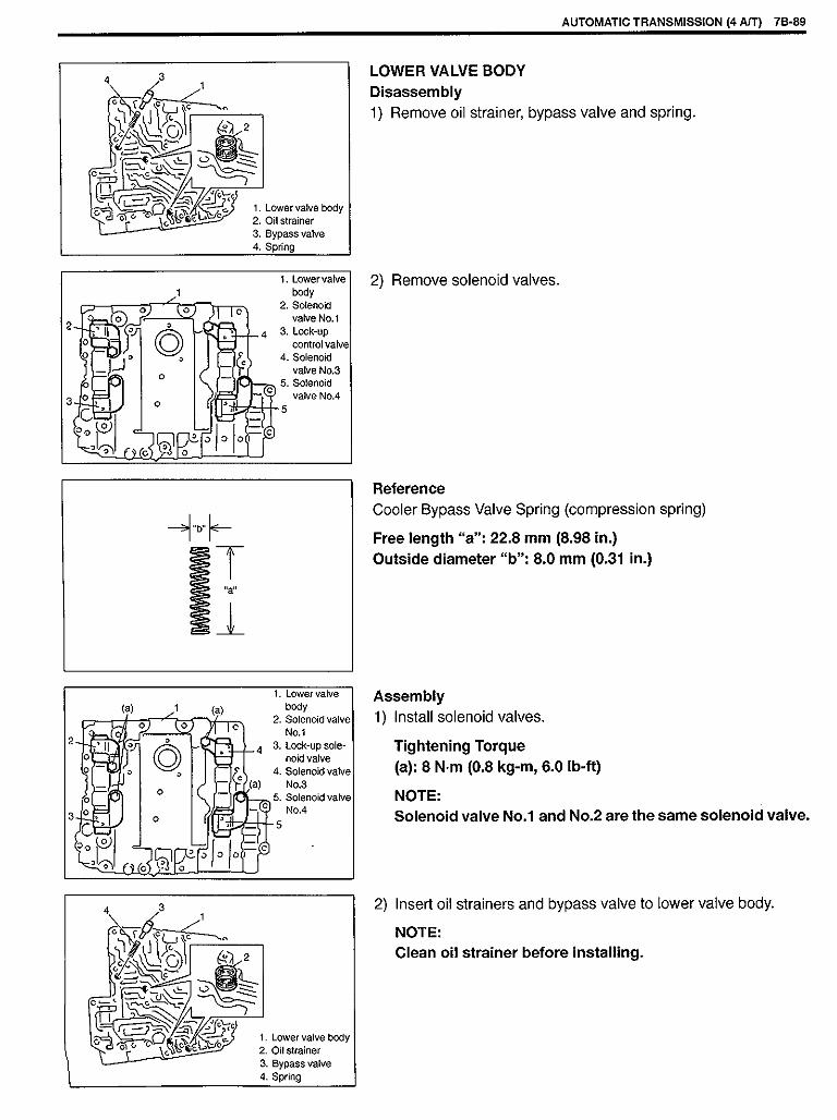
SHIFT SOLENOID VALVES AND A/T FLUIDTEMP. SENSORREMOVAL1) Disconnect negative cable from battery.2) Drain A/T fluid.3) Remove A/T oil pan.4) Disconnect A/T fluid temp. sensor coupler.
1. A/T oil pan
5) Remove one of oil strainer bolts and ground wire for shift sole-noid valve No.1.
6) Disconnect shift solenoid and A/T fluid temp. sensor couplers.7) Remove shift solenoid valves (No.1, No.3 and No.4) and lock-
up solenoid valve.8) Remove valve body ass’y.9) Remove shift solenoid valve No.2.
1. Valve body ass’y2. Coupler3. A/T fluid temp. sensor4. Oil strainer ass’y5. Bolt A6. Bolt B7. Bolt C8. Ground wire9. Oil strainer bolt
AUTOMATIC TRANSMISSION (4 A/T) 7B-55
O/D cut switch ON OFF
Continuity Continuity No continuity
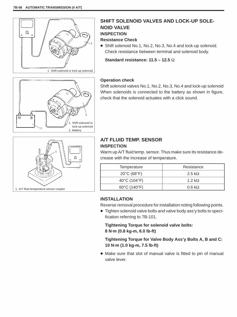
SHIFT SOLENOID VALVES AND LOCK-UP SOLE-NOID VALVEINSPECTIONResistance Check� Shift solenoid No.1, No.2, No.3, No.4 and lock-up solenoid.
Check resistance between terminal and solenoid body.
Standard resistance: 11.5 – 12.5 �
1. Shift solenoid or lock-up solenoid
Operation checkShift solenoid valves No.1, No.2, No.3, No.4 and lock-up solenoidWhen solenoids is connected to the battery as shown in figure,check that the solenoid actuates with a click sound.
1. Shift solenoid orlock-up solenoid
2. Battery
A/T FLUID TEMP. SENSORINSPECTIONWarm up A/T fluid temp. sensor. Thus make sure its resistance de-crease with the increase of temperature.
1. A/T fluid temperature sensor coupler
INSTALLATIONReverse removal procedure for installation noting following points.� Tighten solenoid valve bolts and valve body ass’y bolts to speci-
fication referring to 7B-101.
Tightening Torque for solenoid valve bolts:8 N·m (0.8 kg-m, 6.0 lb-ft)
Tightening Torque for Valve Body Ass’y Bolts A, B and C:10 N·m (1.0 kg-m, 7.5 lb-ft)
� Make sure that slot of manual valve is fitted to pin of manualvalve lever.
7B-56 AUTOMATIC TRANSMISSION (4 A/T)
Temperature Resistance
20�C (68�F) 2.5 k�
40�C (104�F) 1.2 k�
60�C (140�F) 0.6 k�

� Clean mating surface of A/T oil pan and A/T case and install newgasket to A/T oil pan.Tighten bolts to specification.
Tightening Torque(a): 7.5 N·m (0.75 kg-m, 5.5 lb-ft)
1. Magnet2. Gasket3. Oil pan
� Refill A/T fluid referring to 7B-48 and verify that there is no A/Tfluid leakage.
EXTENSION CASE OIL SEALREPLACEMENT1) Lift up vehicle and drain transmission oil.2) Remove propeller shaft No.1 and No.2.
Refer to Section 4B for procedure.3) Remove extension case oil seal by using screwdriver or like.4) Install new differential side oil seal by using special tool.
NOTE:For oil seal installation, press-fit oil seal so that transmis-sion case end face is flush with oil seal end face.
Special Tool(A): 09913-75520
5) Install propeller shafts referring to Section 4B.6) Refill A/T fluid referring to p. 7B-69.
1. Oil seal2. Extension case
AUTOMATIC TRANSMISSION (4 A/T) 7B-57

INSTALLATIONReverse removal procedure noting the following.� Connect ECM and TCM couplers securely.� If the vehicle is equipped with air bag system, be sure to enable
air bag system after TCM and ECM are back in place. Refer to“Enabling Air Bag System” in Section 10B.
REMOVALRemove ECM and separate TCM from ECM bracket.Refer to SECTION 6E for ECM removal.
CAUTION:TCM and ECM consist of highly precise parts, so whenhandling it (or them), be careful not to expose to exces-sive shock.
TRANSMISSION CONTROL MODULE (TCM)
LEARNING CONTROL MEMORY INITIALIZATIONInitialization of learning control memory in TCM should be madeupon replacement of parts as explained below.� Automatic transmission assembly replacement with new or
used one� Any A/T brake component parts replacement such as discs,
plates and flange with new or used one(s)� Any A/T clutch component parts replacement such as discs,
plates and flange with new or used one(s)� Replacement of TCM with used one
1) Turn ignition switch to “ON” position. (Do not start engine.)2) Bring diag. switch terminal of monitor coupler in contact with
ground terminal using service wire.3) Repeat shifting selector lever from “D” to “2” position and vice
versa for 3 times within 10 seconds to complete memory initial-ization.
4) Confirm initialization by DTC set in system referring to “DTCCHECK” in this section.
DTC No.12: completion of initialization is confirmedDTC No.52: initialization is failed
5) If you failed initialization, repeat steps 1) to 3).
NOTE:� “O/D OFF” lamp continues to turn on while initialization.� DTCs which might have been set in system other than No.12
and 52 are also erased by initialization.
1. Monitor coupler2. Diag. switch terminal3. Ground terminal
7B-58 AUTOMATIC TRANSMISSION (4 A/T)


TRANSMISSION UNIT REPAIR OVERHAULNOTE:When transmission is replaced, or when any A/T clutch or brake component parts such as discs, platesand flange are replaced with new or used one(s), learning control memory of TCM should be initialized afterthose replacement referring to “LEARNING CONTROL MEMORY INITIALIZATION” in this section.
DISMOUNTINGNOTE:If automatic transmission is overhauled later on, draining A/T fluid at this point will facilitate work.
1) Remove following parts.� Propeller shafts No.1 and No.2 (refer to SECTION 4B)� Exhaust pipe (refer to SECTION 6K)� Negative cable from battery
2) Disconnect couplers. (2 couplers from wire harness and 1from shift switch)
3) Remove selector rod from shift control shaft lever by removingpin.
4) Remove oil cooler hoses from pipes.
NOTE:To avoid leakage of transmission fluid, plug open ends ofoil cooler pipes and hoses right after they are discon-nected.
5) Remove torque converter housing lower plate.
1. Selector rod2. Shift control
shaft lever3. Pin
6) Remove drive plate bolts.To lock drive plate, engage a flat screwdriver with drive plategear.
7) Remove starting motor.
1. Flat screwdriver2. Wrench
8) With transmission held up on jack, remove engine to transmis-sion bolts and nuts.
9) Remove transmission rear mounting bracket.10) Move transmission to the rear a little and lower it including
torque converter.
WARNING:Be sure to keep transmission horizontal throughoutthe work. Should it be tilted, torque converter mayfall off and cause personal injury and A/T fluid mayflow out.1. Rear mounting bracket
AUTOMATIC TRANSMISSION (4 A/T) 7B-61


4) Remove one of oil strainer bolts and ground wire of shift sole-noid valve No.1.Disconnect couplers from solenoid valves, and A/T fluid tem-perature sensor.Remove A/T fluid temperature sensor and oil strainer assembly.
5) Remove valve body assembly.
NOTE:There are three kinds of bolts fixing valve body ass’y.
6) Remove solenoid harness assembly.
CAUTION:Be careful not to let manual valve fall off when remov-ing valve body assembly.
1. Valve body ass’y2. Coupler3. A/T fluid temp. sensor4. Oil strainer ass’y5. Bolt A6. Bolt B7. Bolt C8. Ground wire9. Oil strainer bolt
7) Remove accumulator pistons and springs.To remove C1, C2 and B1 accumulator pistons and springs,position a rag on pistons to catch each piston.To remove pistons, force low-pressure compressed air (1 kg/cm2, 15 psi, 100 kPa, max) into hole as shown in figure, and popeach piston into the rag.To remove B0 accumulator piston and spring, remove snap ringand accumulator spacer, then remove spring and piston.
NOTE:Do not push accumulator pistons with fingers or anythingbefore removing them. Pushing them may cause com-pressed fluid in accumulator to spew out of hole and get toyour face and clothes.
1. C1 accumulator piston2. C2 accumulator piston3. B1 accumulator piston4. Hole
7B-64 AUTOMATIC TRANSMISSION (4 A/T)


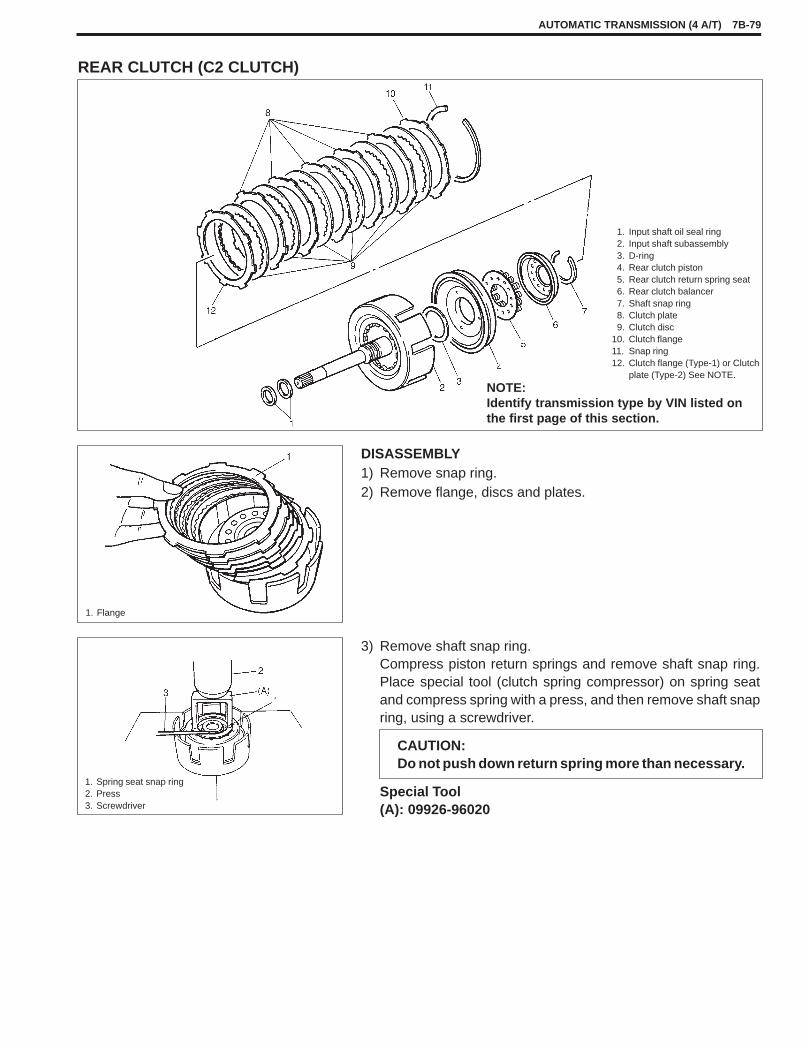
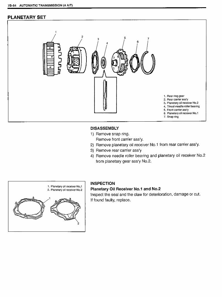
1. Input shaft oil seal ring2. Input shaft subassembly3. D-ring4. Rear clutch piston5. Rear clutch return spring seat6. Rear clutch balancer7. Shaft snap ring8. Clutch plate9. Clutch disc
10. Clutch flange11. Snap ring12. Clutch flange (Type-1) or Clutch
plate (Type-2) See NOTE.
NOTE:Identify transmission type by VIN listed onthe first page of this section.
DISASSEMBLY1) Remove snap ring.2) Remove flange, discs and plates.
1. Flange
3) Remove shaft snap ring.Compress piston return springs and remove shaft snap ring.Place special tool (clutch spring compressor) on spring seatand compress spring with a press, and then remove shaft snapring, using a screwdriver.
Special Tool(A): 09926-96020
CAUTION:Do not push down return spring more than necessary.
1. Spring seat snap ring2. Press3. Screwdriver
AUTOMATIC TRANSMISSION (4 A/T) 7B-79
REAR CLUTCH (C2 CLUTCH)

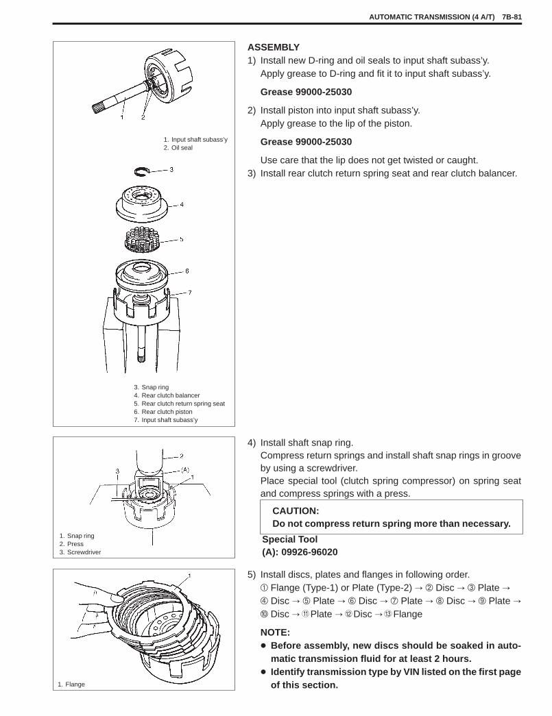
ASSEMBLY1) Install new D-ring and oil seals to input shaft subass’y.
Apply grease to D-ring and fit it to input shaft subass’y.
Grease 99000-25030
2) Install piston into input shaft subass’y.Apply grease to the lip of the piston.
Grease 99000-25030
Use care that the lip does not get twisted or caught.3) Install rear clutch return spring seat and rear clutch balancer.
3. Snap ring4. Rear clutch balancer5. Rear clutch return spring seat6. Rear clutch piston7. Input shaft subass’y
1. Input shaft subass’y2. Oil seal
4) Install shaft snap ring.Compress return springs and install shaft snap rings in grooveby using a screwdriver.Place special tool (clutch spring compressor) on spring seatand compress springs with a press.
CAUTION:Do not compress return spring more than necessary.
Special Tool(A): 09926-96020
1. Snap ring2. Press3. Screwdriver
5) Install discs, plates and flanges in following order.� Flange (Type-1) or Plate (Type-2) � � Disc � � Plate � � Disc � � Plate � � Disc � � Plate � � Disc � Plate � Disc � Plate � Disc � Flange
NOTE:� Before assembly, new discs should be soaked in auto-
matic transmission fluid for at least 2 hours.� Identify transmission type by VIN listed on the first page
of this section.1. Flange
AUTOMATIC TRANSMISSION (4 A/T) 7B-81


1) Install new O-rings (inside and outside) to B2 brake piston, andapply grease to them.
Grease : 99000-25030
2) [In the case of transmission type-1]Install B2 brake piston to transmission case.
[In the case of transmission type-2]Install B2 brake piston with two fingers, which have moundedpart between them, aligned with transmission case hole asshown in figure.
NOTE:Identify transmission type by VIN listed on the first page ofthis section.
3) Install B1 brake piston and B1 & B2 return spring assembly totransmission case.
4) Install snap ring by compressing return spring ass’y thru B2brake piston seat with hydraulic press and special tool.
NOTE:Don’t compress B1 & B2 return spring ass’y more than nec-essary or it may get damaged.
Special Tool(A): 09926-96010
1. Snap ring2. B1 & B2 return spring
ass’y3. B1 brake piston4. B2 brake piston5. O-ring
6. Hydraulic press7. Mounded part of B2
brake piston8. Hole of transmission
case
7B-92 AUTOMATIC TRANSMISSION (4 A/T)
UNIT ASSEMBLY
CAUTION:� Automatic transmission consists of highly precise parts. As even a flaw in a small part may cause
oil leakage or decrease in function, check each part carefully before installation.� Clean all parts with compressed air. Never use wiping cloths or rags.� Before assembling new clutch discs and brake discs, soak them in automatic transmission fluid
for at least 2 hours.� Be sure to use new gaskets and O-rings.� Lubricate O-rings with automatic transmission fluid.� Apply automatic transmission fluid on sliding or rotating surfaces of the parts before assembly.� Use yellow petrolatum grease or Suzuki Super Grease C to retain parts in place.� Be sure to install thrust bearings and races in correct direction and position.� Make sure that snap ring ends are not aligned with one of cutouts and are installed in groove cor-
rectly.� Do not use adhesive cements on gaskets and similar parts.� Be sure to torque each bolt and nut to specification.

5) Install B1 brake discs, plates and flange to B2 brake piston infollowing order.� Plate � � Disc � � Plate � � Disc � � Plate � � Disc �� Plate � � Disc � Plate � Disc � Flange
6) [In the case of transmission type-1]Install snap ring to B2 brake piston.
[In the case of transmission type-2]Install snap ring to B2 brake piston with antirotation protrusionaligned with gap between two fingers having mounded part.
1. Snap ring2. B2 brake piston3. Antirotation protrusion
7) Measure B1 brake stroke and clearance in following manner.
B1 Brake Stroke:Set the dial gauge to 1st & 2nd brake (B1 brake) piston throughB1 brake spring seat hole as shown. Blow compressed air intohole shown in figure. Then measure the difference as the com-pressed air is blown in.
Standard Value for B1 Brake Stroke : 1.75 – 2.00 mm(0.0689 – 0.0787 in.)
B1 Brake Clearance:Blow compressed air into the hole shown in figure.Measure the difference.
Standard Value for B1 Brake Clearance: 1.30 – 2.00 mm(0.0512 – 0.0787 in.)
If the measured value(s) is (are) out of specification, select theflange from table below and repeat this step until the measuredvalues are within specification.
1. Dial gauge2. B1 brake spring seat3. Tip of dial gauge4. B1 brake piston
5. Brake flange6. Air gun7. Transmission case
AUTOMATIC TRANSMISSION (4 A/T) 7B-93
2.875 mm (0.113 in.)
Available Flange Size3.050 mm (0.120 in.)
Available Flange Size(thickness)
3.225 mm (0.127 in.)(thickness)
3.400 mm (0.134 in.)
3.575 mm (0.141 in.)

8) Install B2 brake discs, plates and flange in following order.� Plate � Cushion plate � Plate � Disc � Plate(thick) � Disc � Plate (thick) � Disc Flange
NOTE:Cushion plate has installing direction as shown in figure.
9) Hold above parts with snap ring.
1. Cushion plate2. Front3. Rear
10) Measure B2 brake stroke and clearance in following manner.
B2 Brake Stroke:
Set the dial gauge to reverse brake (B2 brake) piston throughB1 brake spring seat hole as shown. Blow compressed air intohole shown in figure. Then measure the difference as the com-pressed air is blown in.
Standard Value for B2 Brake Stroke : 2.22 – 2.47 mm(0.0874 – 0.0972 in.)
B2 Brake Clearance:Blow compressed air into the hole shown in figure.Measure the difference.
Standard Value for B2 Brake Clearance: 0.60 – 1.70 mm(0.0236 – 0.0669 in.)
If the measured value(s) is (are) out of specification, select theflange from table below and repeat this step until the measuredvalues are within specification.
1. Dial gauge2. B1 brake spring seat3. Tip of dial gauge4. B1 brake piston5. Brake flange6. Air gun7. Transmission case
7B-94 AUTOMATIC TRANSMISSION (4 A/T)
2.36 mm (0.093 in.)
Available Flange Size 2.54 mm (0.100 in.)
(thickness) 2.72 mm (0.107 in.)
2.90 mm (0.114 in.)

11) Install thrust needle roller bearing and rear sun gear. Turn rearsun gear right and left to match the brake discs and the splineof rear sun gear.
12) Install thrust needle roller bearing and planetary set. Turnplanetary set right and left to match the gears of the rear sungear and the gears of the planetary set.
1. Planetary set2. Thrust needle roller bearing3. Rear sun gear
13) Install new inner and outer O-rings to B0 brake piston and ap-ply grease to them.
“A”: Grease 99000-25030
Install brake piston to B0 brake drum.14) Install B0 brake piston & drum ass’y to transmission case, in
such way that the edge A comes at the position as shown infigure. Make sure that the O-rings are not twisted or caught.
15) Place B0 brake piston return spring subass’y on piston. Makesure that each spring fits the holes on the piston.
16) Push down return spring subass’y and install snap ring.
CAUTION:Check that the opening of snap ring does not face thecored-hole of the transmission case.
1. Snap ring2. B0 brake piston return spring subass’y3. B0 brake piston4. O-ring (outer)5. Cored-hole
AUTOMATIC TRANSMISSION (4 A/T) 7B-95

17) Install B0 brake discs, plates and flange in following order.� Plate � � Disc � � Plate � � Disc � � Flange
NOTE:The flat surface of B0 flange must face to B0 disc.
18) Inspect B0 brake piston stroke and clearance by blowing com-pressed air into hole shown in figure.Make sure that the obtained piston stroke and clearance satis-fy the standard value.
To Measure Clearance:
Set dial gauge to the top of B0 brake flange and blow com-pressed air into the hole shown in figure.
To Measure Piston Stroke:
Set dial gauge to the step of B0 brake piston as shown in fig-ure. Blow compressed air into the hole shown in figure andmeasure the value for piston stroke.
Standard Values forClearance : 0.50 – 1.05 mm (0.0197 – 0.0413 in.)Piston stroke : 0.70 – 1.05 mm (0.0275 – 0.0413 in.)
If the measured value(s) is (are) out of specification, select theflange from table below and repeat this step until the measuredvalues are within specification.
1. Dial gauge2. Tip of dial gauge3. Air gun4. Blow compressed air into this hole
Clearance
Piston Stroke
19) Install front sun gear to planetary set.
1. Needle rollerbearing
2. Front sun gear
7B-96 AUTOMATIC TRANSMISSION (4 A/T)
2.35 mm (0.093 in.)
Available Flange Size 2.60 mm (0.102 in.)g(thickness) 2.85 mm (0.112 in.)
3.10 mm (0.122 in.)

20) Install thrust needle roller bearing to intermediate shaft.
1. Thrust needle roller bearing2. Intermediate shaft
21) Install intermediate shaft to transmission case.
1. Intermediate shaft
22) Install rear disc clutch assembly by turning it right and left tomatch the clutch disc of rear disc clutch ass’y and the splineof intermediate shaft.
1. Rear disc clutch ass’y
24) Install front disc clutch assembly by turning it right and left tomatch the clutch disc of front disc clutch ass’y and the splineof follow shaft.
1. Front disc clutch assembly2. Transmission case
23) Install thrust bearing race and thrust needle roller bearing.
“A”: Grease 99000-25030
1. Thrust bearing race2. Thrust needle roller bearing
AUTOMATIC TRANSMISSION (4 A/T) 7B-97

25) Install gasket to transmission case and install oil pump assem-bly to transmission case.
Tightening Torque:(a): 12 N·m (1.2 kg-m, 8.5 lb-ft)
1. Oil pump
26) Measure input shaft end play.Set dial gauge as shown in figure and measure the play of theinput shaft.
Standard Value of Input Shaft End Play: 0.3 – 0.9 mm(0.012 – 0.036 in.)
If the obtained value is out of standard value, select thrustbearing race (installed in step 22) of different thickness shownin table below and adjust the play.
1. Dial gauge2. Input shaft end3. Oil pump
27) Apply grease to oil pump D-ring.Install new gasket to transmission case and install torque con-verter housing.
Tightening Torque:(a): 19 N·m (1.9 kg-m, 14.0 lb-ft)
Grease: 99000-25030
NOTE:Use new bolts.1. Torque converter housing
28) Apply grease to lip of new oil seal and drive in oil seal till it con-tacts with transmission case.
29) After installing new sleeve cover and washers to manual shiftlever, install manual shift shaft and manual shift lever to trans-mission case.
1. Oil seal2. Sleeve cover3. Manual shift lever
4. Manual shift shaft5. Washer
7B-98 AUTOMATIC TRANSMISSION (4 A/T)
Available Thrust Bearing1.3 mm (0.051 in.)
Available Thrust BearingRace Size (thickness)
1.7 mm (0.067 in.)Race Size (thickness)
2.1 mm (0.083 in.)

30) Align hole in manual shift shaft with that in manual shift leverand drive in new manual shift lever pin through sleeve cover.
31) Turn sleeve cover by 90� and caulk securely with pin punch.Then check that manual shift shaft turns smoothly.
1. Pin punch
32) Install detent spring and parking rod as shown in figure.
Tightening Torque(a): 15N·m (1.5 kg-m, 11.0 Ib-ft)
1. Detent spring2. Parking rod
33) Install parking pawl, spring and parking pawl shaft as shownin figure.
1. Parking pawl shaft2. Spring3. Parking pawl
AUTOMATIC TRANSMISSION (4 A/T) 7B-99

34) Install O-rings to each accumulator piston and apply grease orATF to them.
“A”: Grease 99000-25030
35) Install B0 accumulator piston, compression spring gray paintand accumulator spacer.Hold them with snap ring.
NOTE:� Make sure that the snap ring is fitted to the groove of
B1-B0 accumulator cylinder.� Make sure that the O-ring is not twisted or caught when
installing.
36) Install B1 accumulator spring (with light blue paint) and accu-mulator piston.
NOTE:� Make sure that the O-ring is not twisted or caught when
installing.
1. C2 accumulator piston (large)2. O-ring3. C2 accumulator spring (with pink paint)4. B1 accumulator piston (with 1 groove)5. B1 accumulator spring (with light blue paint)6. Snap ring7. Accumulator spacer8. B0 accumulator spring (with white paint)9. B0 accumulator piston
10. C1 accumulator piston (with 2 grooves)11. C1 accumulator spring12. C2 accumulator spring (with orange paint)13. C2 accumulator piston (small)
37) Install wire-to-solenoid assembly.Fix it with sleeve lock plate and a bolt.
NOTE:� Apply grease to O-ring of wire-to-solenoid ass’y.� Match the arrow mark on wire-to-solenoid ass’y with the
sleeve lock plate.Tightening Torque:(a): 8.0 N·m (0.8 kg-m, 6.0 Ib-ft)Grease 99000-25030
1. Wire-to-solenoid ass’y2. Sleeve lock plate
7B-100 AUTOMATIC TRANSMISSION (4 A/T)

38) Install valve body to transmission case.First match the pin of the manual valve lever to the slot of themanual valve.
NOTE:Connect shift solenoid No.2 coupler (green) before tight-ening bolts.Tightening Torque:(a): 10 N·m (1.0 kg-m, 7.5 lb-ft)
1. Valve body ass’y2–1. Shift solenoid No.1 coupler2–2. Shift solenoid No.2 coupler2–3. Shift solenoid No.3 coupler2–4. Shift solenoid No.4 coupler2–5. Lock-up solenoid coupler
3. A/T fluid temp. sensor4. Oil strainer ass’y5. Bolt A6. Bolt B7. Bolt C8. Ground wire9. Oil strainer bolt
39) Connect couplers of wire-to-solenoid to solenoid valves.
40) Install O-ring to oil strainer ass’y.41) Install oil strainer ass’y with ground wire for shift solenoid valve
No.1 to the top of valve body ass’y.Connect A/T fluid temperature sensor coupler.Fix A/T fluid temperature sensor and oil strainer ass’y withbolts.
Tightening Torque:(b): 8 N·m (0.8 kg-m, 6 lb-ft)
AUTOMATIC TRANSMISSION (4 A/T) 7B-101
Bolt Length “a” Pieces
A 25 mm (0.98 in.) 2
B 25 mm (0.98 in.) 7
C 20 mm (0.79 in.) 3
Solenoid Valve Color
1 Natural
2 Green
3 Natural
4 Black
Lock-up Black
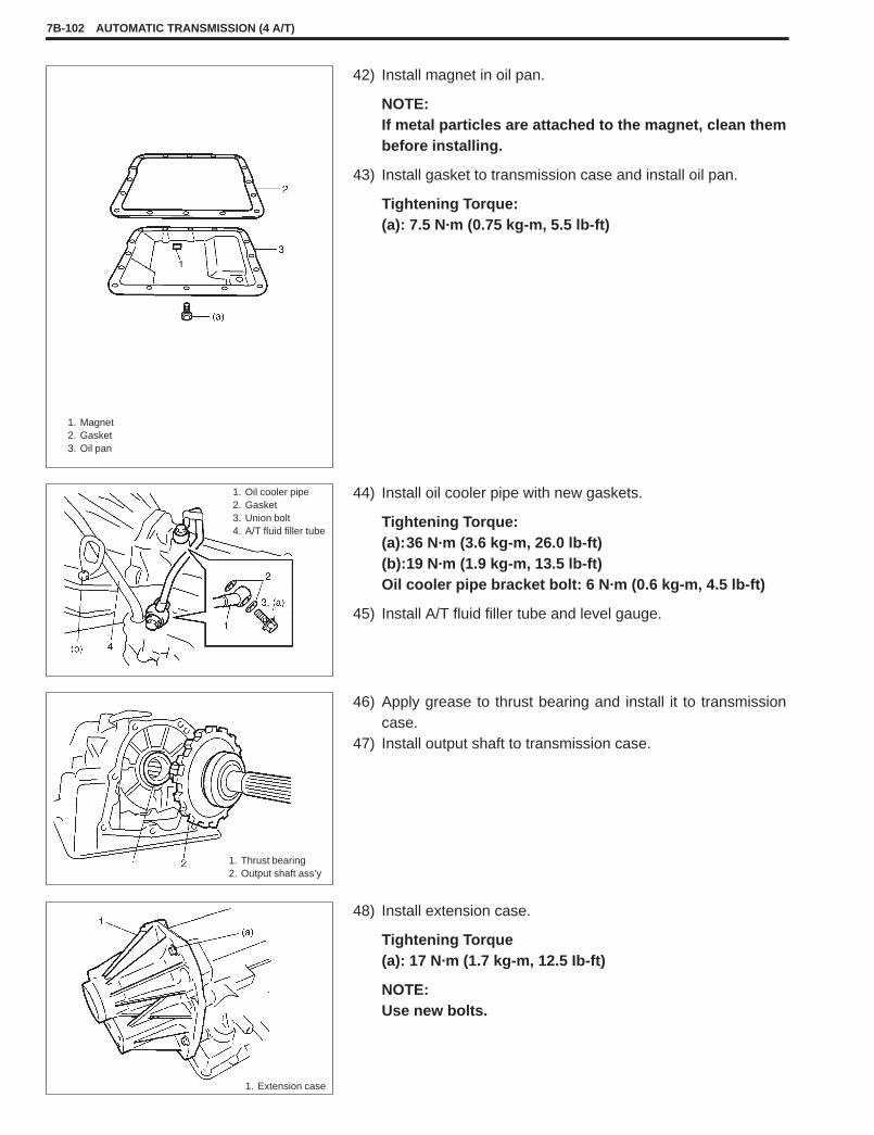
42) Install magnet in oil pan.
NOTE:If metal particles are attached to the magnet, clean thembefore installing.
43) Install gasket to transmission case and install oil pan.
Tightening Torque:(a): 7.5 N·m (0.75 kg-m, 5.5 lb-ft)
1. Magnet2. Gasket3. Oil pan
44) Install oil cooler pipe with new gaskets.
Tightening Torque:(a):36 N·m (3.6 kg-m, 26.0 lb-ft)(b):19 N·m (1.9 kg-m, 13.5 lb-ft)Oil cooler pipe bracket bolt: 6 N·m (0.6 kg-m, 4.5 lb-ft)
45) Install A/T fluid filler tube and level gauge.
1. Oil cooler pipe2. Gasket3. Union bolt4. A/T fluid filler tube
46) Apply grease to thrust bearing and install it to transmissioncase.
47) Install output shaft to transmission case.
1. Thrust bearing2. Output shaft ass’y
48) Install extension case.
Tightening Torque(a): 17 N·m (1.7 kg-m, 12.5 Ib-ft)
NOTE:Use new bolts.
1. Extension case
7B-102 AUTOMATIC TRANSMISSION (4 A/T)

49) Install A/T VSS and turbine revolution sensor.Apply grease to O-ring of each sensor.
Tightening Torque:(a): 8 N·m (0.8 kg-m, 6.0 lb-ft)
50) Install shift switch.Install it temporarily so that the adjustment can be done afterinstalling A/T ass’y back to the vehicle.
Tightening Torque:(b): 18 N·m (1.8 kg-m, 13.0 lb-ft)
1. A/T VSS2. Turbine rev. sensor3. Shift switch
AUTOMATIC TRANSMISSION (4 A/T) 7B-103

51) Install torque converter to input shaft.� Install torque converter, using care not to damage oil seal
of oil pump.� After installing torque converter, check to make sure that
distance “e” is within specification.
Distance “e”: More than 18.0 mm (0.708 in.)
� Check torque converter for smooth rotation.� Apply grease around cup at the center of torque converter.
SUZUKI SUPER GREASE A, 99000-25010
CAUTION:� Before installing converter, make sure that its
pump hub portion is free from nicks, burrs ordamage which may cause oil seal to leak.
� Be very careful not to drop converter on oilpump gear. Damage in gear, should it occur,may cause a critical trouble.
1. Torque converter2. Torque converter housing
7B-104 AUTOMATIC TRANSMISSION (4 A/T)


Prepared by
� � �� ���� ��������
Overseas Service Department
1st Ed. June, 19982nd Ed. Oct., 19983rd Ed. Jan., 2002Printed in Japan
Printing: Jan., 2002 897