sv_102 user manual chapters 1-9
TRANSCRIPT

7/27/2019 SV_102 User Manual Chapters 1-9
http://slidepdf.com/reader/full/sv102-user-manual-chapters-1-9 1/113
ZETOM-CERT
ISO 9001
INSTRUMENTATION FOR SOUND & VIBRATION
MEASUREMENTS AND ANALYSIS
SV 102
DUAL-CHANNEL ACOUSTIC DOSIMETER
USERUSERUSERUSER MANUALMANUALMANUALMANUAL
SVANTEK Sp. z o.o.
WARSAW, July 2008

7/27/2019 SV_102 User Manual Chapters 1-9
http://slidepdf.com/reader/full/sv102-user-manual-chapters-1-9 2/113
SV 102 USER MANUAL _
Notice: This user’s manual presents the software revision named 1.05 / 1.05.9 (cf. the description of the UNIT LABEL position of the DISPLAY list). The succeeding software revisions (marked with the bigger numbers) can slightly change the view of some displays presented in the text of the manual.

7/27/2019 SV_102 User Manual Chapters 1-9
http://slidepdf.com/reader/full/sv102-user-manual-chapters-1-9 3/113
SV 102 USER MANUAL
i
CONTENTS
1 INTRODUCTION 1-1
2 MANUAL CONTROL OF THE INSTRUMENT 2-1
2.1 Control push-buttons on the front panel 2-1 2.2 Input and output sockets of the instrument 2-3
3 SETTING THE INSTRUMENT 3-1
3.1 Basis of the instrument’s control 3-1
3.2 Menu structure - short description of the functionalities 3-3
3.3 Powering of the instrument 3-19
3.4 Initial setup of the instrument 3-21
3.5 Icons 3-22
3.6 Activation of optional functions 3-24
3.7 Memory organisation 3-25
4 MODE AND FUNCTION SELECTION - FUNCTION 4-1
5 INSTRUMENT’S CALIBRATION - CALIBRATION 5-1
5.1 Calibration procedure of the instrument - BY MEASUREMENT 5-1
5.2 History of the calibration - LAST CALIBRATION 5-3
6 MEASUREMENT PARAMETERS SETTING - INPUT 6-1
6.1 Selection of measurement parameters - MEASUREMENT SETUP 6-2
6.1.1 Setting time delay before the start of measurements - START DELAY 6-2 6.1.2 Setting the integration period - INTEGR. PERIOD 6-2
6.1.3 Setting the number of repetition of measurement cycles - REP. CYCLE 6-3
6.1.4 Logger functionality switching On/Off - LOGGER 6-4
6.1.5 Setting period between two writings to the logger’s file - LOGGER STEP 6-4
6.1.6 Logger file name edition - LOGGER NAME 6-4
6.2 Measurement range info - MEASUREMENT RANGE 6-5
6.3 Selection of dose meter parameters - DOSIMETER SETUP 6-6
6.3.1 Setting criterion sound level - CRITERION LEVEL 6-6
6.3.2 Setting criterion sound level - THRESHOLD LEVEL 6-7 6.3.3 Setting criterion sound level - EXCHANGE RATE 6-7
6.4 Setting parameters in channels - LEFT and RIGHT CHANNEL 6-7
6.4.1 Logger results selection in profiles - PROFILE x 6-7
6.5 Setting parameters in a profiles - PROFILE x 6-8
6.5.1 Weighting filter selection in a profile - FILTER 6-9
6.5.2 RMS detector selection - DETECTOR 6-9
6.6 Triggering mode and parameters selection - TRIGGER SETUP 6-9
6.6.1 Audio-event recording - EVENT TRIGGER 6-9
6.6.2 Trigger parameters setting - MEASURE TRIGGER 6-10 6.6.2.1 Switching the triggering on and off - TRIGGER 6-10 6.6.2.2 Selection of the triggering signal - SOURCE 6-11

7/27/2019 SV_102 User Manual Chapters 1-9
http://slidepdf.com/reader/full/sv102-user-manual-chapters-1-9 4/113
SV 102 USER MANUAL _
6.6.2.3 Setting the level of the triggering signal - LEVEL 6-12 6.6.2.4 Setting the speed of the triggering signal changes - GRADIENT 6-12
6.6.3 Trigger parameters in logger setting - LOGGER TRIGGER 6-12 6.6.3.1 Switching the logger triggering on and off - TRIGGER 6-13 6.6.3.2 Selection of the triggering signal in logger - SOURCE 6-13
6.6.3.3 Setting the level of the triggering signal in the logger - LEVEL 6-13 6.6.3.4 Selection of the number of the results to be saved in the logger before the
fulfilment of the triggering condition - PRE 6-13 6.6.3.5 Selection of the number of the results to be saved in the logger after the
fulfilment of the triggering condition - POST 6-14
6.7 Selection of 1/1 octave spectrum parameters - SPECTRUM 6-14
6.7.1 Selecting the weighting filter in 1/1 OCTAVE analysis - FILTER 6-14
6.7.2 Logging PEAK and RMS results from spectrum - LOGGER PEAK and LOGGERRMS 6-15
7 DATA AVAILABLE ON THE DISPLAY - DISPLAY 7-1
7.1 Selection of the modes of results presentation - DISPLAY MODES 7-1 7.1.1 Switching on/off spectrum view - SPECTRUM 7-3
7.1.2 Switching on/off three profiles view - 3 PROFILES 7-3
7.1.3 Setting on/off statistics view - STATISTICS 7-4
7.1.4 Setting on/off logger view - LOGGER 7-6
7.1.5 Setting on/off the view of the file description - FILE INFO 7-6
7.2 Setting parameters of graphical presentation modes - DISPLAY SETUP 7-7
7.2.1 Setting the scale of presentation and display’s grid - DISPLAY SCALE 7-7 7.2.1.1 Scaling the vertical axis of graphical mode presentation - DYNAMIC 7-7 7.2.1.2 Switching on/off the grid in graphical presentation - GRID 7-8
7.2.2 Setting main results view - MAIN VIEW 7-8 7.2.3 Setting 3 profiles view - 3 PROFILES VIEW 7-9
7.2.4 Setting the view of statistics presentation mode - STATISTICS VIEW 7-9
7.2.5 Setting the parameters of logger files presentation - SPECTRUM VIEW 7-10 7.2.5.1 Selection of spectrum type for the presentation - TYPE 7-10 7.2.5.2 Selection of MAX spectrum for the presentation - MAX 7-10 7.2.5.3 Selection of MIN spectrum for the presentation - MIN 7-10
7.2.6 Setting the parameters of logger files presentation - LOGGER VIEW 7-11 7.2.6.1 Selecting the shape of graphical presentation - VIEW 7-11 7.2.6.2 Setting time to be presented - TIME 7-11
7.3 Selection of logger’s file to display presentation - LOGGER VIEW 7-12 7.4 Setting the parameters of the display - SCREEN SETUP 7-14
7.4.1 Setting contrast of the display - CONTRAST 7-14
7.4.2 Automatic switch off of the backlight - BACKLIGHT TIMEOUT 7-14
7.5 Checking the state of internal battery - BATTERY 7-15
7.6 Checking specification of the instrument - UNIT LABEL 7-15
8 SAVING THE MEASUREMENT RESULTS - FILE 8-1
8.1 Saving files in the instrument’s memory - SAVE and SAVE NEXT 8-3
8.2 Controlling the data storing in the instrument’s memory - SAVE OPTIONS 8-5
8.2.1 Saving data starting from the same address - RAM FILE 8-5

7/27/2019 SV_102 User Manual Chapters 1-9
http://slidepdf.com/reader/full/sv102-user-manual-chapters-1-9 5/113
SV 102 USER MANUAL
iii
8.2.2 Replacement of the existing files by the new ones - REPLACE 8-6
8.2.3 Controlling the measurement statistics savings - SAVE STATISTICS 8-6
8.2.4 Automatical saving of measurement results - AUTO SAVE 8-7
8.3 Loading the files with the measurement results - LOAD 8-8
8.4 Removing a file with the measurement results from memory - DELETE 8-9
8.5 Removing all files with measurement results from memory - DELETE ALL 8-12
8.6 Merging file space - DEFRAGMENTATION 8-12
8.7 Checking the contents of the memory - CATALOGUE 8-13
8.8 Checking the free space in the memory - FREE SPACE 8-15
8.9 Saving setup files in the instrument’s memory - SAVE SETUP 8-15
8.10 Loading the files with the setup settings - LOAD SETUP 8-18
8.10.1 Loading setup file - FILE SETUP 8-19
8.10.2 Standard setup loading - STANDARD SETUP 8-19
9 SETUP MENU - SETUP 9-1
9.1 Setting the language of the user interface - LANGUAGE 9-2
9.2 Return to the factory settings - CLEAR SETUP 9-2
9.3 Day time limits selection - DAY TIME LIMITS 9-3
9.4 Exposure time setting - EXPOSURE TIME 9-3
9.5 Available parameters of the Ext. I/O port selection - EXTERNAL I/O SETUP 9-4
9.5.1 Mode selection of the Ext. I/O port - MODE 9-4
9.5.2 Digital output-function selection of the Ext. I/O socket in left channel - FUNCTION 9-5
9.5.3 Polarisation selection of the digital output signal - POLARISATION 9-5
9.5.4 Active level selection of the digital output signal - ACTIVE LEVEL 9-5
9.5.5 Source signal selection for the alarm pulse generation - SOURCE 9-5
9.5.6 Alarm level selection on the digital output of Ext. I/O - ALARM LEVEL 9-6
9.6 Selection of keyboard settings - KEYBOARD 9-6
9.6.1 Switching the key lock on - KEY LOCK 9-6
9.6.2 <Shift> push-button working mode selection - SHIFT 9-7
9.7 Switching on/off the compensation filter - MICROPHONE 9-7
9.8 Detector’s type selection in the LEQ calculations - RMS INTEGRATION 9-7
9.9 Programming the instrument’s internal Real Time Clock - RTC 9-8
9.10 Setting ten statistical levels - STATISTICAL LEVELS 9-9
9.11 Programming the instrument’s internal timer - TIMER 9-10
9.11.1 Selecting the mode of the timer function - MODE 9-10
9.11.2 Setting day of the instrument’s switch on - START DAY 9-10
9.11.3 Setting hour of the instrument’s switch on - START HOUR 9-11
9.11.4 Selecting the mode of the timer function - REPETITION 9-11
9.11.5 Description of the exemplary timer function execution 9-11
9.12 Warnings selection - WARNINGS 9-12
9.12.1 Saving the measurement results in a file - RESULTS NOT SAVED 9-13

7/27/2019 SV_102 User Manual Chapters 1-9
http://slidepdf.com/reader/full/sv102-user-manual-chapters-1-9 6/113
SV 102 USER MANUAL _
LIST OF FIGURESSV 102 instrument with the microphones ................................................... ........................................................... .... 1-2 Control push-buttons of the SV 102 instrument........................................................................ ................................. 2-1 Top cover of the SV 102 instrument in 1:1 scale.......... ............................................................ ................................. 2-3 Bottom cover of the SV 102 instrument in 1:1 scale ...................................................... ........................................... 2-3 Front panel of the SV 102 instrument in 1:1 scale.......................................................... ........................................... 2-4
Rear panel of the SV 102 instrument in 1:1 scale........................................................... ........................................... 2-4 Highlighted elements of the main list................................................................................................. ........................ 3-1 RECENT ITEMS windows (after double pressing of Menu) .................................................. .................................. 3-1 MENU window (a) and the elements of INPUT list (b) ........................................................... ................................. 3-2 MEASUREMENT SETUP window........................................................... ........................................................... .... 3-2 MEASUREMENT SETUP window; INTEGR. PERIOD position accessible ...................................................... .... 3-2 INTEGRATION PERIOD position after pressing the <> or <> push-buttons, respectively............................... 3-2 Displays after three consecutive pressing of <ESC> push-button from MEASUR. SETUP window........................ 3-2 Displays during and after the accessing FREE SPACE window........................................................ ........................ 3-3 Control diagram of FUNCTION list........................................................... ........................................................... .... 3-3 Control diagram of CALIBRATION list .................................................... ........................................................... .... 3-5 Control diagram of the INPUT list in DOSE METER mode............................................................. ........................ 3-8 Control diagram of DISPLAY list .................................................... ........................................................... ............ 3-12 Control diagram of FILE list............................................................. ........................................................... ............ 3-15 Control diagram of SETUP list................................................................... ........................................................... .. 3-19 BATTERY windows with different sources powering the instrument: AA batteries (a) and USB power (b) ......... 3-20 Displays with “Battery” icon (a) and with BATTERY window (b).......................................... ............................... 3-20 Displays with “Computer” icon (a) and with BATTERY window (b).................. ................................................... 3-20 SCREEN SETUP windows with BACKLIGHT TIMEOUT active (a), and not active (b) ..................................... 3-20 Displays after switching on the instrument ........................................................... ................................................... 3-21 Display in one profile presentation mode ................................................... ........................................................... .. 3-21 Display options in simplified version (for SINGLE CHANNEL mode, DOSIMETER & 1/1 OCTAVE
function) .................................................. ............................................................ ......................................... 3-22 Display with all available icons ........................................................ ........................................................... ............ 3-23 FUNCTION window with MODE selected (a) and MODE window with DUAL CHANNEL mode selected
(b) ................................................... ........................................................... ................................................... 3-24 FUNCTION window with MEASUR. FUNCTION selected (a) and MEASUR. FUNCTION windows with
DOSE & 1/1 OCTAVE (b) and SLM & 1/1 OCTAVE selected (c) .......................................................... .. 3-24 Displays during the entering of the access code to a function.................................................................................. 3-24 Displays after unsuccessful verification of the access code ...................................................... ............................... 3-24 Scheme of the instrument’s memory organisation .......................................................... ......................................... 3-25 Main list with FUNCTION text selected (a) and FUNCTION list opened with MODE text selected (b)... .............. 4-1 MEASUREMENT FUNCTION window opened with DOSE METER text selected (a),
DOSE & 1/1 OCTAVE text selected (b), SLM text selected (c) SLM &1/1 OCTAVE text selected (d) ...... 4-1 Activation of optional functions ....................................................... ........................................................... .............. 4-1 Main list with CALIBRATION text selected............................................................................................... .............. 5-1 CALIBRATION window, channel selection ........................................................ ..................................................... 5-1 CALIBRATION window with LEFT CHANNEL text selected; BY MEASUREMENT text selected and
BY MEASUREMENT window opened .................................................... ..................................................... 5-2 Displays during the calibration measurement ....................................................... ..................................................... 5-2 Displays after the measurements (a) and after the acceptance of the value of the calibration factor (b).................... 5-3 CALIBRATION list with LAST CALIBRATION text selected (a) LAST CALIBRATION window opened
with ten calibration records (b)...... ............................................................ ..................................................... 5-3 Displays with LAST CALIBRATION records ..................................................... ..................................................... 5-4 Empty LAST CALIBRATION window ..................................................... ........................................................... .... 5-4 Main list with INPUT text selected....................................................................... ..................................................... 6-1 INPUT window in DOSE METER mode ................................................... ........................................................... .... 6-1 Exemplary displays with not active sub-lists of INPUT list................................................................................... .... 6-2 MEASUREMENT SETUP windows........................................................................................................... .............. 6-2 MEASUREMENT SETUP windows; the setting of START DELAY with 1-second step ....................................... 6-2 MEASUREMENT SETUP windows; INTEGR. PERIOD setting with 1-second step.............................................. 6-3 MEASUREMENT SETUP windows; INTEGR. PERIOD setting with 1-minute step.............................................. 6-3 MEASUREMENT SETUP windows; INTEGR. PERIOD setting with 1-hour step ................................................. 6-3

7/27/2019 SV_102 User Manual Chapters 1-9
http://slidepdf.com/reader/full/sv102-user-manual-chapters-1-9 7/113
SV 102 USER MANUAL
v
MEASUREMENT SETUP windows; REP. CYCLE setting with the step equal to one.............. ..............................6-3 Displays with the deactivated and activated LOGGER..............................................................................................6-4 LOGGER STEP setting; available values from 1 second to 1 hour ....................................................... ....................6-4 LOGGER NAME edition in MEASUREMENT SETUP ................................................... ....................................... 6-4 Displays during the attempt of overwriting the existing file............................................................................. ..........6-4 Relations between INTEGR. PERIOD and LOGGER STEP ...................................................... ..............................6-5
INPUT window with MEASUREMENT RANGE selected (a) and opened (b) ........................................................ 6-6 Displays when the level of the signal is too low.........................................................................................................6-6 DOSIMETER SETUP selected in INPUT window and DOSIMETER SETUP window.......................................... 6-6 DOSIMETER SETUP windows with CRITERION LEVEL selection......................................................................6-6 DOSIMETER SETUP windows with THRESHOLD LEVEL selection ......................................................... ..........6-7 DOSIMETER SETUP windows with EXCHANGE RATE selection ................................................... ....................6-7 INPUT windows, LEFT CHANNEL and RIGHT CHANNEL texts selected ........................................................... 6-7 LEFT CHANNEL windows; PROFILE x selection...................................................................................................6-8 PROFILE 1 LEFT; LOGGER result selection...........................................................................................................6-8 PROFILE 1 LEFT windows in SLM modes; available weighting filters and detectors ............................................. 6-8 INPUT windows; PROFILE 1; PROFILE 2 and PROFILE 3 selected......................................................................6-8 PROFILE(x) windows; the selection of the RMS detector .......................................................... ..............................6-9 TRIGGER SETUP selected in INPUT window and TRIGGER SETUP window opened in dosimeter modes......... 6-9 TRIGGER SETUP selected in INPUT window and TRIGGER SETUP window opened in SLM modes ................6-9 Displays in the EVENT TRIGGER window............................................................................................................6-10 Displays in the MEASURE TRIGGER window....................................................... ............................................... 6-10 MEASURE TRIGGER window...............................................................................................................................6-10 MEASURE TRIGGER windows with SLOPE modes selected ................................................... ............................6-11 MEASURE TRIGGER windows with LEVEL modes selected...............................................................................6-11 MEASURE TRIGGER window with GRAD + mode selected................................................................................6-11 MEASURE TRIGGER window with SOURCE signal selection.............................................................................6-12 MEASURE TRIGGER window with LEVEL selection in SLOPE + mode.................................................... ........6-12 MEASURE TRIGGER window with GRADIENT selection (1 dB/ms)..................................................................6-12 LOGGER TRIGGER windows............................................................. ........................................................... ........6-13 LOGGER TRIGGER windows with not active SOURCE signal line.................................................... ..................6-13
LOGGER TRIGGER window with LEVEL selection (1-dB step up) ................................................... ..................6-13 LOGGER TRIGGER windows with PRE selection.................................................................................................6-14 LOGGER TRIGGER windows with POST selection ......................................................... ..................................... 6-14 SPECTRUM selected in INPUT window and SPECTRUM window opened........................................ ..................6-14 SPECTRUM windows with FILTER selection........................................................................................................6-15 SPECTRUM windows with LOGGER PEAK and LOGGER RMS selection......................................................... 6-15 Main list with DISPLAY text highlighted..................................................................................................................7-1 DISPLAY window with DISPLAY MODES text selected.......................................................... ..............................7-1 Switching between all available presentation modes in one-channel mode................................................................ 7-2 Display after the end of the measurements with the file’s name the data are saved-in ............................................... 7-2 DISPLAY MODES windows with SPECTRUM.......................................................................................................7-3 Displays in SPECTRUM mode for 1/1 OCTAVE analysis (LEFT (1L) and RIGHT (1R) channel).........................7-3 Displays with opening of logger plot for selected 1/1 OCTAVE centre frequency....................................................7-3
Setting on and off the accessibility of three-profiles presentation mode.......................................................... ..........7-3 Measurement results in 3 PROFILES mode...............................................................................................................7-4 Results in 3 PROFILES..............................................................................................................................................7-4 Results in 3 PROFILES mode with selection of the profile ......................................................... ..............................7-4 Results in 3 PROFILES mode with selection of statistical level................................................................................7-4 Setting on (a) and off (b) the accessibility of statistics presentation mode................................................................. 7-5 Results presented in the statistics presentation mode......................................................... ........................................ 7-5 Instrument’s Lxx statistical levels presented in graphical form.................................................................................. 7-5 Statistics presentation mode, VIEW: EXTENDED ............................................................ ....................................... 7-5 Results presented in statistic presentation mode during the measurements................................................................7-6 Setting on and off the possibility of presentation the results saved in the logger ....................................................... 7-6 Different presentation modes of the results stored in logger (extended, full, normal)................................................ 7-6 Setting on and off the logger’s file description presentation mode ........................................................ ....................7-6 Exemplary contents of FILE INFO window...............................................................................................................7-6 DISPLAY window with DISPLAY SETUP selected.................................................................................................7-7

7/27/2019 SV_102 User Manual Chapters 1-9
http://slidepdf.com/reader/full/sv102-user-manual-chapters-1-9 8/113
SV 102 USER MANUAL _
DISPLAY SETUP window in SLM and 1/1 OCTAVE and DISPLAY SCALE one................................................ 7-7 DISPLAY SCALE windows with the possible values of DYNAMIC parameter .................................................. .... 7-7 Results stored in logger presented with different DYNAMIC (160 dB, 80 dB, 40 dB, 20 dB, 10 dB) ..................... 7-8 DISPLAY SCALE windows with the grid switched on and off................................................................... .............. 7-8 Displays with the grid switched on and off......... ............................................................ ........................................... 7-8 DISPLAY SETUP window, the MAIN VIEW text selected .................................................... ................................. 7-8
MAIN VIEW window, VIEW selection..................................................... ........................................................... .... 7-8 MAIN VIEW, NORMAL and LARGE VIEW................................. ........................................................... .............. 7-9 DISPLAY SETUP window with 3 PROFILES VIEW text selected ........................................................... .............. 7-9 3 PROFLES VIEW windows, VIEW selection .................................................... ..................................................... 7-9 3 PROFILES presentation mode, NORMAL VIEW and EXTENDED VIEW..................................................... .... 7-9 DISPLAY SETUP window with STATISTICS VIEW selected and STATISTICS VIEW windows ....................... 7-9 STATISTICS presentation mode, NORMAL VIEW and EXTENDED VIEW.................................................... .. 7-10 DISPLAY SETUP window with SPECTRUM VIEW text highlighted....................................................... ............ 7-10 SPECTRUM VIEW windows with TYPE selection.............................................................................................. .. 7-10 SPECTRUM VIEW windows with MAX spectrum selection........................................................... ...................... 7-10 SPECTRUM VIEW windows with MIN spectrum selection ................................................... ............................... 7-11 DISPLAY SETUP windows with LOGGER VIEW text highlighted......... ........................................................... .. 7-11 LOGGER VIEW windows with available values of VIEW parameter.............................................. ...................... 7-11 Presentation of displays with different VIEW parameter; EXTENDED, FULL and NORMAL............................. 7-11 Displays with the possible values of TIME parameter.......................................... ................................................... 7-11 Possible values of TIME parameter, REAL TIME and AVAILABLE TIME (more than 1 day).......................... .. 7-12 DISPLAY window with LOGGER VIEW text highlighted............................................................... ...................... 7-12 LOGGER VIEW windows with the selection of the file to be seen......................................................................... 7-12 LOGGER VIEW windows with the scrolling of the file to be seen................................................... ...................... 7-13 LOGGER VIEW window in the case when the files do not exist ...................................................... ...................... 7-13 Displays with the selected logger’s file; the change of the cursor position..................... ......................................... 7-13 Displays with the selected logger’s file; the change of the profile ..................................................... ...................... 7-13 Displays with the selected logger’s file; the change of the result from a profile (PEAK, MAX, MIN, RMS)......... 7-13 DISPLAY window with SCREEN SETUP text highlighted................................. ................................................... 7-14 SCREEN SETUP windows; the change of the contrast........................................................... ................................ 7-14
SCREEN SETUP windows; the BACKLIGHT TIMEOUT active and not active .................................................. 7-14 DISPLAY window with BATTERY selected and BATTERY windows for different powering sources................ 7-15 DISPLAY window with UNIT LABEL text highlighted.......................................................... ............................... 7-15 UNIT LABEL windows opened and scrolled with the <>, <> push-buttons..................................................... 7-15 Main list; FILE text highlighted.................................................................. ........................................................... .... 8-2 FILE window...................................................... ............................................................ ........................................... 8-2 Display after the attempt to perform an unavailable operation during measurement in progress............................... 8-2 Saving a file using SAVE option ...................................................... ........................................................... .............. 8-3 Display during the selection of the character’s position to be edited.............................. ........................................... 8-3 Display during the selection of the character ........................................................ ..................................................... 8-3 Displays during the attempt of overwriting the existing file, changing the name and saving data............... .............. 8-4 Displays with illustrated SAVE NEXT option ..................................................... ..................................................... 8-4 Display after the SAVE operation when there were no results for storing................................................................. 8-4
Displays after the attempt to overwrite a file if the REPLACE is not active ......................................................... .... 8-5 FILE window with SAVE OPTIONS text highlighted ................................................... ........................................... 8-5 SAVE OPTIONS window; selection of RAM FILE in SLM modes........................................................... .............. 8-5 SAVE OPTIONS window; selection of REPLACE ....................................................... ........................................... 8-6 Displays during the file saving when REPLACE is switched off and on.................................. ................................. 8-6 SAVE OPTIONS window; selection of SAVE STATISTICS.................................................. ................................. 8-6 SAVE OPTIONS window; deactivation of AUTO SAVE option..................................................... ........................ 8-7 Display after attempt of setting AUTO SAVE option with too short INT. PERIOD................................... .............. 8-7 Switching AUTO SAVE on; FILE NAME confirmation and return to FILE window .............................................. 8-7 Displays after the incorrect file name edition ....................................................... ..................................................... 8-8 Loading a file..... ........................................................... ............................................................ ................................. 8-8 LOAD window with NO FILES message............................................................. ..................................................... 8-8 Exemplary result files associated with the same logger file (&LOG99) ...................................................... .............. 8-9 Exemplary displays during the loading and checking the contents of a DOSE METER file..................................... 8-9 Deleting a file ..................................................... ............................................................ ......................................... 8-10

7/27/2019 SV_102 User Manual Chapters 1-9
http://slidepdf.com/reader/full/sv102-user-manual-chapters-1-9 9/113
SV 102 USER MANUAL
vii
RESULT FILES selected to be deleted and the flash memory does not contain any file................................. ........8-10 Selection of LOGGER FILE to be deleted...............................................................................................................8-10 SETUP file selected to be deleted............................................................................................................................8-11 Execution of the @SET3 file deletion......................................................................................................................8-11 Influence of the execution of the @SET3 file deletion on the memory space.......................................................... 8-11 Execution of the @SET4 file deletion and the influence of this process on the memory space ............................... 8-11
Deleting all files ...................................................... ............................................................ ..................................... 8-12 Execution of defragmentation operation ......................................................... ......................................................... 8-13 Message in the case when the execution of DEFRAGMENTATION operation is unnecessary..............................8-13 Result of the FILES DEFRAGMENTATION operation .................................................... ..................................... 8-13 CATALOGUE text highlighted in FILE window.....................................................................................................8-13 CATALOGUE window when the memory is empty........................................................... ..................................... 8-14 Contents of CATALOGUE window ..................................................... ........................................................... ........8-14 Exemplary result files associated with the same logger file (&LOG99) in the CATALOGUE window.................. 8-14 FREE SPACE text highlighted in FILE window......................................................................................................8-15 FREE SPACE window after the execution of DELETE ALL operation..................................................................8-15 FREE SPACE window with the number depending on the measurements and operations performed..................... 8-15 SAVE SETUP text highlighted in FILE window ...................................................... ............................................... 8-16 Saving SETUP using SAVE NEXT option..............................................................................................................8-16 SAVE SETUP window, SAVE option selection......................................................................................................8-16 Display during the process of setting the character in the edited name....................................................................8-16 Display during the selection of the character’s position to be edited ..................................................... ..................8-16 Displays during the attempt of overwriting the existing file, changing the name and saving data ...........................8-17 Saving SETUP file using SAVE NEXT option........................................................................................................8-17 Saving setup with SAVE NEXT option and the message in the case when the file already exists...........................8-18 Displays during and after the execution of the SAVE operation..............................................................................8-18 Displays after the attempt to overwrite a file if REPLACE is active........................................................................8-18 FILE window with LOAD SETUP text highlighted and LOAD SETUP window with available options ...............8-19 FILE SETUP window; selection the file for loading................................................................................................8-19 Display during the execution of LOAD SETUP operation .......................................................... ............................8-19 STANDARD SETUPS parameters ....................................................... ........................................................... ........8-20
STANDARD SETUP loading..................................................................................................................................8-20 Display in the main list; SETUP text highlighted.......................................................................................................9-1 SETUP list of the instrument......................................................................................................................................9-1 SETUP window with LANGUAGE text highlighted and LANGUAGE windows with all available languages........9-2 Exemplary displays with the various available language versions of the user interface.............................................9-2 SETUP window with CLEAR SETUP text highlighted.............................................................................................9-2 Displays with the request for the confirmation for CLEAR SETUP execution...................................... ....................9-2 Displays during and after the execution of CLEAR SETUP function........................................................................9-3 SETUP window with DAY TIME LIMITS text highlighted and displays with available DAY TIME LIMITS .......9-3 SETUP window with EXPOSURE TIME text highlighted........................................................................................9-3 EXPOSURE TIME setting.........................................................................................................................................9-3 SETUP list with EXTERNAL I/O SETUP text highlighted and channel selection in EXT. I/O SETUP
window............................................................................................................................................................9-4
EXTERNAL I/O SETUP windows; MODE selection in LEFT CHANNEL (a) and RIGHT CHANNEL (b) ..........9-4 MEASURE TRIGGER windows; SOURCE selection...............................................................................................9-4 EXTERNAL I/O SETUP windows; FUNCTION selected.......................................................... ..............................9-5 EXTERNAL I/O SETUP windows; POLARISATION selection .......................................................... ....................9-5 EXTERNAL I/O SETUP windows; ACTIVE LEVEL selection...............................................................................9-5 EXTERNAL I/O SETUP windows; SOURCE selection .................................................... ....................................... 9-5 EXTERNAL I/O SETUP windows; ALARM LEVEL setting...................................................................................9-6 SETUP window with KEYBOARD text highlighted.......................................................... ....................................... 9-6 KEYBOARD windows; available KEY LOCK settings..................................................... ....................................... 9-6 Display after the beginning of measurement when the Key lock is ON ........................................................... ..........9-6 Denied access to the files after switching KEY LOCK On.......................................................... ..............................9-7 KEYBOARD windows; available SHIFT settings.....................................................................................................9-7 SETUP window with MICROPHONE text highlighted and MICROPHONE windows; deactivation of
COMPENSATION filter ........................................................... ........................................................... ..........9-7

7/27/2019 SV_102 User Manual Chapters 1-9
http://slidepdf.com/reader/full/sv102-user-manual-chapters-1-9 10/113
SV 102 USER MANUAL _
SETUP window with RMS INTEGRATION text highlighted and displays with the available options of RMS
INTEGRATION.......................................................... ........................................................... ........................ 9-8 SETUP window with RTC text highlighted...................................... ........................................................... .............. 9-8 RTC windows with the time selection ........................................................ ........................................................... .... 9-8 SETUP window with STATISTICAL LEVELS text selected........................................................... ........................ 9-9 STATISTICAL LEVELS windows.................................................. ........................................................... .............. 9-9
Selection of statistical level (results) in 3 PROFILE mode................................... ..................................................... 9-9 Selection of statistical level (results) in one profile mode in SLM modes............................................................. .. 9-10 SETUP window with TIMER text highlighted..................................................... ................................................... 9-10 TIMER windows; mode selection............................................................... ........................................................... .. 9-10 TIMER windows; setting day of the instrument’s switch on .................................................... ............................... 9-11 TIMER windows; setting hour and minute of the instrument’s switch on ................................................... ............ 9-11 TIMER windows; setting REPETITION parameter....................................................... ......................................... 9-11 TIMER windows; setting REPETITION parameter (cont.)......................................................................... ............ 9-11 Exemplary settings made for the desired execution of TIMER function ..................................................... ............ 9-12 Counting down during the warming up of the instrument after switching it on ..................................................... .. 9-12 Displays during the executing of TIMER function (TIMER icon is active) .......................................................... .. 9-12 SETUP window with WARNINGS text highlighted ...................................................... ......................................... 9-13 WARNINGS windows; RESULTS NOT SAVED selected ..................................................... ............................... 9-13 Displays with LAST RESULTS NOT SAVE warning ................................................... ......................................... 9-13

7/27/2019 SV_102 User Manual Chapters 1-9
http://slidepdf.com/reader/full/sv102-user-manual-chapters-1-9 11/113
SV 102 USER MANUAL
1-1
1 INTRODUCTION
The SV 102 is digital, type 2 dual-channel dosimeter dedicated for occupational health and safetyacoustic monitoring task. The binaural dose measurements and the 1/1 octave analysis aresimultaneously performed. Octave analysis provides direct data for the design of the ear-protectors.Together with Audio Events Recording (AER) option, these functionalities show the new reference
standard on the acoustic dose measurement field, now commonly available in compact size instrument.
Dosimeter is offered with one or two dedicated SV 25D ceramic microphones in ½” housing.It ensures the very easy calibration by direct usage of commonly available acoustic calibrators. Moreover,SV 25D smart sensor, with built-in TEDS (Transducer Electronic Data Sheet), offers automatic calibrationfunction. The very robust casing of SV 25D, together with the special mounting clip and dedicatedheadband, make that microphones can be very easy attached in extremely short distance from the humanears.
SV 25S smart sensor with TEDS, is dedicated for the measurements under headphones orearmuffs using MIRE technique (Microphone-In-Real-Ear). With a special adapter, it can be alsocalibrated with commonly available acoustic calibrators. The SV 102 together with SV 25S are designedfor individual real-world test of the earmuffs noise reduction ratio.
The SV 102 can be also used as a dual-channel type 2 sound level meter and real-time 1/1 octaveanalyser. Three acoustic profiles per channel allow parallel measurements with independently definedfilters and RMS detector time constants. Advanced time-history logging for each profile, togetherwith spectra saving and audio-events recording provide complete information about measured signal,which is saved in non-volatile internal memory with the capacity up to 64 MB. Data files are easilydownloaded to any PC using USB interface and SvanPC+ software.
Instrument is powered from two AA standard or rechargeable batteries (separate chargeris required) as well as the USB interface.
SV 102 as DOSIMETER / SLM / ANALYSER
• Standards: IEC 61252-1993; ANSI S1.25-1991, Type 2 : IEC 61672:2002
• Acoustic dosimeter mode: Leq, Spl, Peak, SEL, DOSE, D_8h, LAV, SEL8, PSEL, E, E_8h, “PeaksCounter” and more
• Measurement simultaneous to the 1/1 octave analysis
• SLM Mode: Leq, Spl, SEL, LEPd, Lden, Ltm3, Ltm5, Statistics - Ln (L1-L99), LMax, LMin, LPeak
• Simultaneous measurement in three profiles with independent set of filters and detectors
• Weighting filters: A, C and Z
• RMS Detector: Digital True RMS detector with Peak detection, resolution 0.1 dBTime Constants: Slow, Fast, Impulse
• Microphone: SV 25D, Type 2, ceramic microphone, 1/2" casing with built-in preamplifier & integratedcable
• SV 25S, Type 2, ceramic microphone, special version of the SV 25D for measurements in real ear -
under ear-protectors (option)
• SV 25D and SV 25S have built-in TEDS functionality for the automatic calibration
• Measurement range: 45 dBA RMS ÷ 141 dBA Peak
• Frequency range: 20 Hz ÷ 8 kHz, sampling rate 24 kHz
• Dynamic range: 100 dB
• Data Logger: Time-history logging of RMS / Max / Min / Peak results to internal memory with time stepdown to 1 second, up to 24 measurement results logged simultaneously
• Audio Recorder: Time-domain-signal events recorder (option)
• Dual-channel measurement mode with second microphone SV 25D or SV 25S (option)
• Dual-channel 1/1 octave real-time analysis and spectra logging, 9 filters with centre frequencies from
31.5 Hz to 8 kHz, Type 1, IEC 61260 (option)

7/27/2019 SV_102 User Manual Chapters 1-9
http://slidepdf.com/reader/full/sv102-user-manual-chapters-1-9 12/113
SV 102 USER MANUAL _
Notice: The software options can be purchased in any time, as they require for their activation only the introduction of the special code.
SV 102 instrument with the microphones
The current list of SV 102 options and accessories is presented below:SV 102 Single-Channel DosimeterSV 102_1 Dual-Channel Dosimeter (including second SV 25D_RED)SV 102_LIC_1 1/1 octave analysis for SV 102 or SV 102_1SV 102_LIC_2 Second channel activation for single-channel SV 102 without SV 25D_RSV 102_LIC_15 Event recorder option*(under development)SV 25D_B Dosimeter microphone with integrated preamplifier, TEDS and cable for SV 102-BLACKSV 25D_R Dosimeter microphone with integrated preamplifier, TEDS and cable for SV 102-RED
SV 102 accessories included:SV 25D_B, SC 56, 2xAA batteries, SvanPC+ version 1.xx for Windows2000/XP software

7/27/2019 SV_102 User Manual Chapters 1-9
http://slidepdf.com/reader/full/sv102-user-manual-chapters-1-9 13/113
SV 102 USER MANUAL
2-1
2 MANUAL CONTROL OF THE INSTRUMENT
The control of the instrument is developed in the fully conversational way. User can managethe operation of the instrument by selecting the proper option from the Menu. Thanks to that,the number of the control push-buttons of the instrument is reduced to four.
2.1 Control push-buttons on the front panel
On the front panel of the instrument, there are located the following control push-buttons:
1. <Shift>, (backlight - if held),
2. <>, (<> if pressed with <Shift>)
3. <>, (<> if pressed with <Shift>)
4. <ENTER>, (<ESC> if pressed with <Shift>, <On/Off> if held)
Control push-buttons of the SV 102 instrument
<Shift>
The second function of a push-button (written in red colour on a push-button) can be used when
the <Shift> push-button is pressed. This push-button can be used in two different ways:
• As SHIFT in the keyboard (e.g. while typing the filename); both <Shift> and the second push-buttonmust be pressed in parallel;
• As 2nd Fun, this push-button can be pressed and released before pressing the second one orpressed in parallel (while operating in “2nd Fun” mode, see the following notice) with
the second push-button.
Notice: The operation of this push button can be set as the “Shift” mode or the “2nd Fun.” mode in the KEYBOARD window of the SETUP list (see Chapter with the SETUP list description).
Notice: <ENTER> push-button held for at least 5 seconds switches the instrument on and off.
Start/StopThe Start/Stop (<> pressed together with <ENTER>) enables one to start the measurement
process, when the instrument is not measuring or to stop it, when the instrument is in courseof the measurement.
7/27/2019 SV_102 User Manual Chapters 1-9
http://slidepdf.com/reader/full/sv102-user-manual-chapters-1-9 14/113
SV 102 USER MANUAL _
2-2
<ENTER>
This push-button enables one to enter the selected operation mode or to confirm control options.
MenuThe Menu (<> and <> pressed together) enables the user to enter the main list containing six
sub-lists: FUNCTION, CALIBRATION, INPUT, DISPLAY, FILE and SETUP. Each of the mentioned
above sub-lists consists of the different elements. These main sub-lists will be detailed describedin the following chapters of the manual. Double pressed Menu enters the list containing eight last opened
sub-lists. It often speeds up the control of the instrument.
SaveThe Save (<> pressed together with the <ENTER>) enables the user to save measurement
results as a file in the internal instrument’s memory. There are two available functions: SAVE NEXT - savea file with the name increased by one (e.g. 02JAN0, 02JAN1, 02JAN3) and SAVE - save a filewith the edited name. (AUTO SAVE option is implicitly set in the instrument to save each file automatically
after the measurement)
<ESC>This push-button (<Shift> pressed together with <ENTER>) closes the control lists, sub-lists or
windows. It acts in opposition to the <ENTER> push-button. When the window is closed pressingthe <ESC> push-button, any changes made in it are ignored in almost all cases.
<>, <>
These push-buttons enable one, in particular, to:
• select the options in an active position in the "horizontal direction" (e.g. Integration period: 1s, 2s, 3s,
… etc.),
• select the measurement result to be displayed (e.g. PEAK, MAX, MIN, etc.) in One Profile and3 PROFILES modes of result’s presentation),
• control the cursor in LOGGER and STATISTICS modes of result’s presentation,
<>, <> The <>, <> (<>, <> pressed together with <Shift>) push-buttons enable one, in particular,
to:
• change the mode of result’s presentation,
• switch the active position in a sub-list.
• programme the Real Time Clock (RTC) and TIMER.

7/27/2019 SV_102 User Manual Chapters 1-9
http://slidepdf.com/reader/full/sv102-user-manual-chapters-1-9 15/113
SV 102 USER MANUAL
2-3
2.2 Input and output sockets of the instrument
The microphone inputs are placed on the instrument’s top cover. In the case of one-channeloperation, the user should use left microphone input. The user should plug Lemo connector until it clicks.The full description of the signals connected to the sockets is given in the Appendix C.
Top cover of the SV 102 instrument in 1:1 scale
In the bottom cover, there are two sockets: USB and I/O. The clamping screw is located between
the two sockets.
Bottom cover of the SV 102 instrument in 1:1 scale
The USB 1.1 interface is the serial interface working with 12 MHz clock. Thanks to its speed,
it is widely used in all PC.
The additional multi-purpose input / output socket, called I/O port, is a RCA Jack socket. On thissocket, in the case when the ANALOGUE OUTPUT functionality is selected, the signal from the input
of the analogue / digital converter (before the correction) is available. This signal can be registered usingmagnetic recorder or observed on the oscilloscope. The DIGITAL INPUT as another functionality servesas the external trigger, while the DIGITAL OUTPUT is used to generate the trigger pulse or alarm pulse
from the instrument.
Notice: Switch instrument off before connecting it to any other device
(e.g. a Personal Computer).
7/27/2019 SV_102 User Manual Chapters 1-9
http://slidepdf.com/reader/full/sv102-user-manual-chapters-1-9 16/113
SV 102 USER MANUAL _
2-4
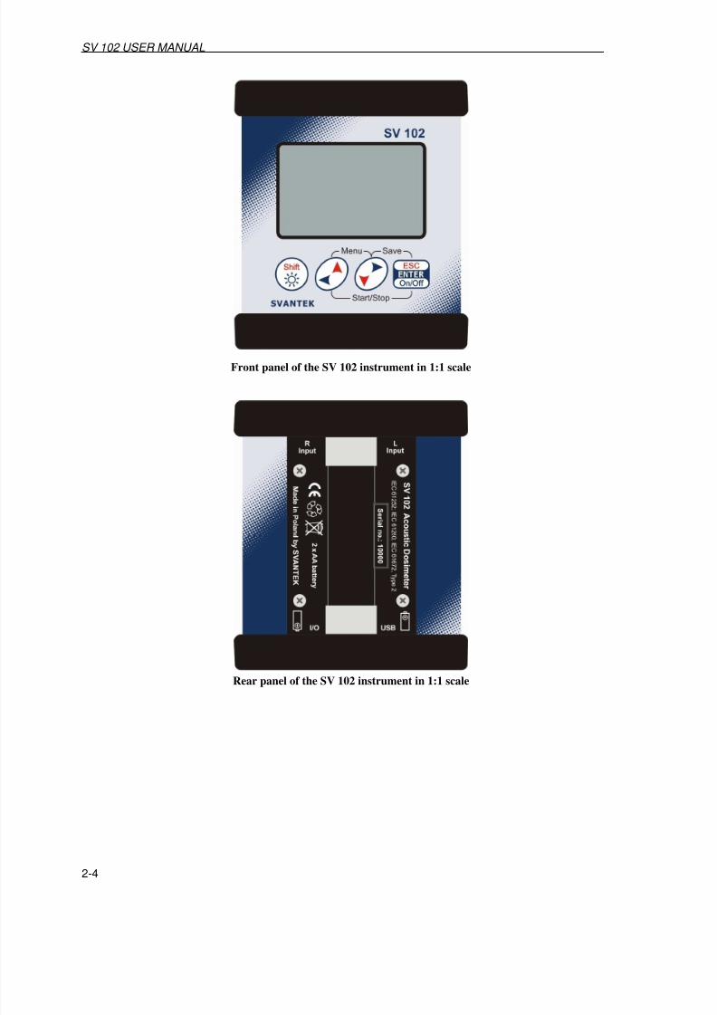
Front panel of the SV 102 instrument in 1:1 scale
Rear panel of the SV 102 instrument in 1:1 scale
7/27/2019 SV_102 User Manual Chapters 1-9
http://slidepdf.com/reader/full/sv102-user-manual-chapters-1-9 17/113
SV 102 USER MANUAL
3-1
3 SETTING THE INSTRUMENT
In order to perform the measurements using the instrument the user has only to plug-inthe microphones and to switch the power on.
Notice: The user has to press <ENTER> push-button and hold it for at least 5 seconds in order to switch the power On/Off.
3.1 Basis of the instrument’s control
The instrument is controlled by means of four push-buttons of the keyboard. Using these push-buttons one can access all available functions.
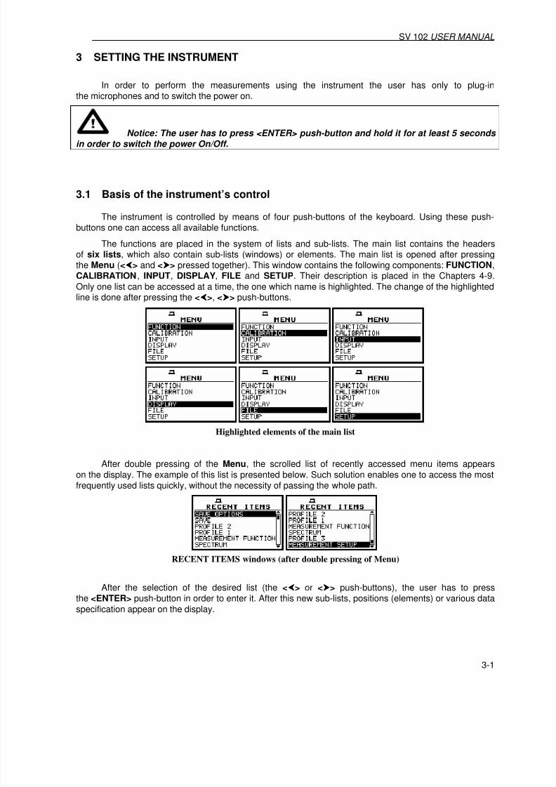
The functions are placed in the system of lists and sub-lists. The main list contains the headersof six lists, which also contain sub-lists (windows) or elements. The main list is opened after pressing
the Menu (<> and <> pressed together). This window contains the following components: FUNCTION,CALIBRATION, INPUT, DISPLAY, FILE and SETUP. Their description is placed in the Chapters 4-9.
Only one list can be accessed at a time, the one which name is highlighted. The change of the highlightedline is done after pressing the <>, <> push-buttons.
Highlighted elements of the main list
After double pressing of the Menu, the scrolled list of recently accessed menu items appears
on the display. The example of this list is presented below. Such solution enables one to access the mostfrequently used lists quickly, without the necessity of passing the whole path.
RECENT ITEMS windows (after double pressing of Menu)
After the selection of the desired list (the <> or <> push-buttons), the user has to pressthe <ENTER> push-button in order to enter it. After this new sub-lists, positions (elements) or various data
specification appear on the display.

7/27/2019 SV_102 User Manual Chapters 1-9
http://slidepdf.com/reader/full/sv102-user-manual-chapters-1-9 18/113
SV 102 USER MANUAL _
3-2
a) b)
MENU window (a) and the elements of INPUT list (b)
Next pressing of the <ENTER> push-button enables one to access mentioned above sub-lists.
MEASUREMENT SETUP window
The desired position of a list is accessed after pressing the <Shift> and <> or <> push-button.
MEASUREMENT SETUP window; INTEGR. PERIOD position accessible
The change of the value in a selected position is performed by pressing the <> or <> push-
buttons.
...
INTEGRATION PERIOD position after pressing the <> or <> push-buttons, respectively
The <ENTER> push-button is used for the confirmation of the selection in a position andfor closing the opened window. The window is closed ignoring any changes made in it by pressingthe <ESC> push-button.
Displays after three consecutive pressing of <ESC> push-button from MEASUR. SETUP window
As it was mentioned, some of the windows end with the windows informing the user about the stateof the instrument, available memory, not existing files or loggers, standards fulfilled by the unit, etc.In order to close such window the user has to press the <ESC> push-button.
7/27/2019 SV_102 User Manual Chapters 1-9
http://slidepdf.com/reader/full/sv102-user-manual-chapters-1-9 19/113
SV 102 USER MANUAL
3-3
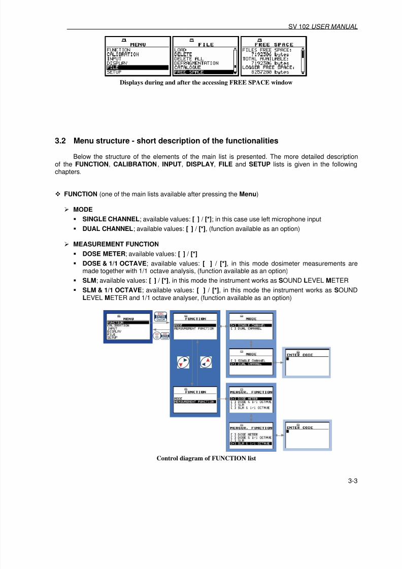
Displays during and after the accessing FREE SPACE window
3.2 Menu structure - short description of the functionalities
Below the structure of the elements of the main list is presented. The more detailed descriptionof the FUNCTION, CALIBRATION, INPUT, DISPLAY, FILE and SETUP lists is given in the followingchapters.
FUNCTION (one of the main lists available after pressing the Menu)
MODE
SINGLE CHANNEL; available values: [ ] / [*]; in this case use left microphone input
DUAL CHANNEL; available values: [ ] / [*], (function available as an option)
MEASUREMENT FUNCTION
DOSE METER; available values: [ ] / [*]
DOSE & 1/1 OCTAVE; available values: [ ] / [*], in this mode dosimeter measurements aremade together with 1/1 octave analysis, (function available as an option)
SLM; available values: [ ] / [*], in this mode the instrument works as SOUND LEVEL METER
SLM & 1/1 OCTAVE; available values: [ ] / [*], in this mode the instrument works as SOUNDLEVEL METER and 1/1 octave analyser, (function available as an option)
Control diagram of FUNCTION list

7/27/2019 SV_102 User Manual Chapters 1-9
http://slidepdf.com/reader/full/sv102-user-manual-chapters-1-9 20/113
SV 102 USER MANUAL _
3-4

7/27/2019 SV_102 User Manual Chapters 1-9
http://slidepdf.com/reader/full/sv102-user-manual-chapters-1-9 21/113
SV 102 USER MANUAL
3-5
CALIBRATION (one of the main lists available after pressing the Menu)
LEFT CHANNEL
• BY MEASUREMENT o CAL. LEVEL; available values of calibration level in dB: 90 dB .. 134 dB
• LAST CALIBRATION; it enables the user to view the last calibration records
RIGHT CHANNEL
• BY MEASUREMENT o CAL. LEVEL; available values of calibration level in dB: 90 dB .. 134 dB
• LAST CALIBRATION; it enables the user to view the last calibration records
Control diagram of CALIBRATION list

7/27/2019 SV_102 User Manual Chapters 1-9
http://slidepdf.com/reader/full/sv102-user-manual-chapters-1-9 22/113
SV 102 USER MANUAL _
3-6
INPUT (one of the main lists available after pressing Menu)
MEASUREMENT SETUP
START DELAY; available values of the delay before starting the executionof the measurements: 1s .. 60s
INTEGR. PERIOD; available values of the integration time: Inf, 1s .. 24h
REP. CYCLE; available values for the measurement cycles, which has to be repeated: Inf, 1 ..1000
LOGGER off/ on – saving measurement results in instrument’s logger memory
• LOGGER STEP; available values of the step with which the measurement resultsare saved in an instrument’s logger: 1s .. 1 h
• LOGGER NAME editing the name of the logger’s file
MEASUREMENT RANGE; range of the sound level measurement in dB (RMS 45 dB -138 dB,PEAK 77 dB -141 dB)
DOSIMETER SETUP (in DOSE METER mode, path: FUNCTION / MEASUREMENT FUNCTION / DOSE METER)
CRITERION LEVEL; available values of the permitted steady state noise level: 80 dB, 84 dB,85 dB, 90 dB
THRESHOLD LEVEL; available values of the noise threshold: None, 70 dB, 75 dB, 80 dB,85 dB, 90 dB
EXCHANGE RANGE; available values of the exchange range (the amount by whichthe permitted noise level may increase if the exposure time is halved): 2 .. 5 dB
LEFT CHANNEL
PROFILE 1, it enables to select results to be stored in the logger memory: PEAK, MAX, MIN,RMS (setting possible only when LOGGER is switched on (path: INPUT / MEASUREMENT SETUP / LOGGER On )
PROFILE 2, it enables to select results to be stored in the logger memory: PEAK, MAX, MIN,RMS (setting possible only when LOGGER is switched on (path: INPUT / MEASUREMENT SETUP / LOGGER On )
PROFILE 3, it enables to select results to be stored in the logger memory: PEAK, MAX, MIN,RMS (setting possible only when LOGGER is switched on (path: INPUT / MEASUREMENT SETUP / LOGGER On )
RIGHT CHANNEL
PROFILE 1, it enables to select results to be stored in the logger memory: PEAK, MAX, MIN,RMS (setting possible only when LOGGER is switched on (path: INPUT / MEASUREMENT SETUP / LOGGER On )
PROFILE 2, it enables to select results to be stored in the logger memory: PEAK, MAX, MIN,
RMS (setting possible only when LOGGER is switched on (path: INPUT / MEASUREMENT SETUP / LOGGER On )
PROFILE 3, it enables to select results to be stored in the logger memory: PEAK, MAX, MIN,RMS (setting possible only when LOGGER is switched on (path: INPUT / MEASUREMENT SETUP / LOGGER On )
PROFILE 1
FILTER A
DETECTOR; available values of the detector time constant used in the first profile:
o IMP., FAST, SLOW; available detector time constant in sound measurements

7/27/2019 SV_102 User Manual Chapters 1-9
http://slidepdf.com/reader/full/sv102-user-manual-chapters-1-9 23/113
SV 102 USER MANUAL
3-7
PROFILE 2
FILTER C
DETECTOR; available values of the detector time constant used in the second profile:
o IMP., FAST, SLOW; available detector time constant in sound measurements
PROFILE 3
FILTER Z DETECTOR; available values of the detector time constant used in the third profile:
o IMP., FAST, SLOW; available detector time constant in sound measurements
SPECTRUM; it appears on the display in the case of 1/1 OCTAVE analyser
• FILTER; available types of the digital weighting filter used during 1/1 OCTAVE analysis:
o Z, A, C; available weighting filters used during 1/1 OCTAVE analysis
• LOGGER PEAK; it enables the user to save PEAK results from 1/1 OCTAVE function
in logger memory; available values: [ ] or [√√√√]
• LOGGER RMS; it enables the user to save RMS results from 1/1 OCTAVE function
in logger memory; available values: [ ] or [√√√√]
TRIGGER SETUP; it appears on the display in the case of SLM modes
MEASURE TRIGGER; it enables the user to switch on or off the triggering
o TRIGGER; available options: SLOPE+, SLOPE–, LEVEL+, LEVEL–, GRAD+
o SOURCE; available sources are RMS(1) and (for SLOPE) EXT. I/O
o LEVEL; available values 24 .. 136 dB
o (for GRAD+ selected in TRIGGER), GRADIENT; available values: 1 .. 100 dB/ms
LOGGER TRIGGER; it enables the user to switch on or off the triggering in logger
o TRIGGER; available values LEVEL+, LEVEL–
o SOURCE: RMS (1)
o LEVEL; available values 24 .. 136 dB
o PRE; available values 0 .. 50o POST; available values 0 .. 200

7/27/2019 SV_102 User Manual Chapters 1-9
http://slidepdf.com/reader/full/sv102-user-manual-chapters-1-9 24/113
SV 102 USER MANUAL _
3-8
Control diagram of the INPUT list in DOSE METER mode

7/27/2019 SV_102 User Manual Chapters 1-9
http://slidepdf.com/reader/full/sv102-user-manual-chapters-1-9 25/113
SV 102 USER MANUAL
3-9
DISPLAY (one of the main lists available after pressing Menu)
DISPLAY MODES; it enables the user to activate ([√√√√]) or switch off ([ ]) the available modesof result’s presentation
SPECTRUM; available values: [√√√√] or [ ], position available only when 1/1 octave function isactivated
3 PROFILES; available values: [√√√√] or [ ]
STATISTICS; available values: [√√√√] or [ ]
LOGGER; available values: [√√√√] or [ ]
FILE INFO; available values: [√√√√] or [ ]
DISPLAY SETUP
DISPLAY SCALE
• DYNAMIC; available values of the dynamics of graphical modes of the result’s presentation:160dB, 80dB, 40dB, 20dB, 10dB
• GRID; available values [ ] or [√√√√]
MAIN VIEW
• VIEW; available views: NORMAL, LARGE
3 PROFILES VIEW
• VIEW; available views: NORMAL, EXTENDED
STATISTICS VIEW
• VIEW; available views: NORMAL, EXTENDED
SPECTRUM VIEW
• TYPE; available views: AVERAGED, INSTANTANEOUS, MAX, MIN, PEAK
• MAX; available values: [ ], [ ]
• MIN; available values: [ ], [ ]
LOGGER VIEW;
• VIEW; available logger views: EXTENDED, FULL, NORMAL
• TIME; available time settings for logger: REAL TIME, AVAILABLE TIME
LOGGER VIEW
FILE NO.; number of the files in the instrument’s logger containing the results
of the measurements LOG. FILE; name of the viewed logger’s file
RECORDS; number of records in the viewed logger’s file
P(1)L; settings for logger in PROFILE 1 for LEFT CHANNEL (INPUT list), available valuesPEAK, MAX, MIN, RMS
P(2)L; settings for logger in PROFILE 2 for LEFT CHANNEL (INPUT list), available valuesPEAK, MAX, MIN, RMS
P(3)L; settings for logger in PROFILE 3 for LEFT CHANNEL (INPUT list), available valuesPEAK, MAX, MIN, RMS

7/27/2019 SV_102 User Manual Chapters 1-9
http://slidepdf.com/reader/full/sv102-user-manual-chapters-1-9 26/113

7/27/2019 SV_102 User Manual Chapters 1-9
http://slidepdf.com/reader/full/sv102-user-manual-chapters-1-9 27/113

7/27/2019 SV_102 User Manual Chapters 1-9
http://slidepdf.com/reader/full/sv102-user-manual-chapters-1-9 28/113

7/27/2019 SV_102 User Manual Chapters 1-9
http://slidepdf.com/reader/full/sv102-user-manual-chapters-1-9 29/113

7/27/2019 SV_102 User Manual Chapters 1-9
http://slidepdf.com/reader/full/sv102-user-manual-chapters-1-9 30/113
SV 102 USER MANUAL _
3-14
LOGGER DEFRAGMENT.; it enables the user to recover the memory, which was previouslyused by the deleted logger files; the confirmation is required before the executionof this operation: “Are you sure?”
The text DEFRAGMENTATION .. unnecessary PRESS ANY KEY is displayed whenthe instrument’s memory was empty before trial of the defragmentation or when there wereno deleted files
CATALOGUE; it enables the user to verify the list of files in the memory; the NO FILES textis displayed in the case when the instrument’s memory is empty
FREE SPACE; it informs the user about the size of the available memory for savingthe measurement results in the file (FILES FREE SPACE), the TOTAL AVAILABLE bytesof the memory (the number displayed in the FILES FREE SPACE increased by the memory whichwas previously used by the deleting files), the next two numbers givenin the FREE SPACE window, named LOGGER FREE SPACE and LOGGER AVAILABLE characterize the logger files memory in the same way
SAVE SETUP; saves the current settings of the instrument; with <
>, <
> push-buttons one canchoose between two modes: SAVE NEXT and SAVE. These are similar to the options availablewhile saving result files. SAVE mode enables to choose the file name manually.In the SAVE NEXT mode the file name will be set automatically
LOAD SETUP; it enables the user to verify the list of setup files in the memory and to loadthe previously saved settings of the instrument; the NO FILES text is displayed in the case whenthere is no setup files

7/27/2019 SV_102 User Manual Chapters 1-9
http://slidepdf.com/reader/full/sv102-user-manual-chapters-1-9 31/113
SV 102 USER MANUAL
3-15
Control diagram of FILE list

7/27/2019 SV_102 User Manual Chapters 1-9
http://slidepdf.com/reader/full/sv102-user-manual-chapters-1-9 32/113
SV 102 USER MANUAL _
3-16
SETUP (one of the main lists available after pressing Menu)
LANGUAGE; it allow the user to choose the instrument’s interface language; available values:GERMAN, ENGLISH, SPANISH, ITALIAN, FLEMISH, FRENCH, HUNGARIAN, POLISH,RUSSIAN, TURKISH
CLEAR SETUP; it enables the user to return to the factory settings of the instrument;
the confirmation has to be done before the execution of this function Are you sure?
DAY TIME LIMITS; specifies the time limits for the instrument to operate in the DOSE METER mode with the full 8h working time assumed; available values: 6h–18h, 7h–19h
EXPOSURE TIME; available values: 1 s .. 8 h
EXTERNAL I/O SETUP
LEFT CHANNEL
• MODE o ANALOG OUT
o DIGITAL OUT • FUNCTION; available: TRIG. PULSE or ALARM PULSE o POLARISATION: POS. / NEG. (in the case of TRIG. PULSE) o ACTIVE LEVEL; available values: LOW / HIGH, (in the case of ALARM PULSE)o SOURCE; available values: PEAK(1), SPL(1), LEQ(1), (in the case of
ALARM PULSE)o ALARM LEVEL; available values: 30.0 dB .. 140 dB (in the case of ALARM PULSE)
RIGHT CHANNEL
• MODE;o ANALOG OUT o DIGITAL IN
• FUNCTION; available: EXT. TRIGGER
KEYBOARD
KEY LOCK; it enables to lock the keyboard, available options: Off or On.
SHIFT; available modes of the <Shift> push-button: Shift or 2nd Fun.
MICROPHONE
COMPENSATION; available values: [√√√√] or [ ]
RMS INTEGRATION
RMS INTEGRATION; available values of detector’s type: LINEAR or EXPONENTIAL
RTC
RTC; it enables the user to set the internal real time clock and date of the instrument
STATISTICAL LEVELS; available levels N=1, 10, 20, ... 90
TIMER; it enables the user to set time of the self switching on of the instrument
MODE; specifies the mode of automatic power on; available values:
• Off
• SINGLE; (START DAY; specifies the date of automatic power on; START HOUR; specifiesthe time of automatic power on)
• REGULAR; (START DAY; specifies the date of automatic power on; START HOUR;specifies the time of automatic power on, REPETITION; specifies time after which nextautomatic measurement will be executed)

7/27/2019 SV_102 User Manual Chapters 1-9
http://slidepdf.com/reader/full/sv102-user-manual-chapters-1-9 33/113
SV 102 USER MANUAL
3-17
WARNINGS
RESULTS NOT SAVE; it enables the user to switch on or off the warning that the results
of the measurement were not saved in the memory; available values: [√√√√] or [ ]

7/27/2019 SV_102 User Manual Chapters 1-9
http://slidepdf.com/reader/full/sv102-user-manual-chapters-1-9 34/113
SV 102 USER MANUAL _
3-18

7/27/2019 SV_102 User Manual Chapters 1-9
http://slidepdf.com/reader/full/sv102-user-manual-chapters-1-9 35/113

7/27/2019 SV_102 User Manual Chapters 1-9
http://slidepdf.com/reader/full/sv102-user-manual-chapters-1-9 36/113
SV 102 USER MANUAL _
3-20
a) b)
BATTERY windows with different sources powering the instrument: AA batteries (a) and USB power (b)
When the instrument is powered from batteries, the “Battery” icon is presented on the topof the display. When voltage of the batteries is too low, the icon is flashing. To change the batteriesthe user has to switch off the instrument, unscrew black bottom cover of the instrument, changethe batteries and install bottom cover. The fully charged NiMH batteries ensure more than 24 hoursof the continuous work of the instrument (in single channel mode and with the backlight off). The batterycondition can be checked by means of the BATTERY function. It is also presented continuouslyon the display by means of the “Battery” icon.
a) b)
Displays with “Battery” icon (a) and with BATTERY window (b)
When there is a connection to USB interface (USB Device socket is connected by meansof the cable to a PC), the “Computer” icon is presented on the top of the display and in the BATTERY window, there is the USB POWER 5.0 V message.
a) b)
Displays with “Computer” icon (a) and with BATTERY window (b)
Notice: In the case when “Battery” icon is flashing, it is strongly recommended to use as soon as possible the external power adapter or USB interface. In the other case the instrument after a while will be switched off by itself!
The backlight of the display can be activated by <Shift> push-button pressed and held. For savingthe power of the battery, in the normal daylight operation it is recommended to keep the backlight off.
The user can set the BACKLIGHT TIMEOUT (path: DISPLAY / SCREEN SETUP / BACKLIGHT TIMEOUT ), which will cause the self-made backlight switching off in the case when
the keyboard is not used during the last 30 seconds. If it happened the first pressing of any push-buttonswitches the backlight on.
a) b)
SCREEN SETUP windows with BACKLIGHT TIMEOUT active (a), and not active (b)

7/27/2019 SV_102 User Manual Chapters 1-9
http://slidepdf.com/reader/full/sv102-user-manual-chapters-1-9 37/113
SV 102 USER MANUAL
3-21
3.4 Initial setup of the instrument
The instrument passes the self-test after switching on (in this time the producer and the nameof the instrument is displayed on the display) and then it enters the sound mode. The default displaymode for result’s presentation is one profile.
a) b)
Displays after switching on the instrument
To start the measurements the user has to press the Start/Stop. The result of the measurement is
displayed with the unit of the measurement in so-called one profile mode. On the left side of the display,the analogue-like indicator is presented. On the bottom of the display, there is a channelfrom which comes the measurement (Ch.: LEFT or RIGHT). On the top of the display (under the iconsline) there are the following data: the function name (DOSE, D_8h, LEPd, LAV, LEQ, PEAK, MAX, E,
SEL, E_8h, SEL8, PSEL, PCTC, PCTP, RMS) the detector time constant (Imp., Fast, Slow - whenthe detector is exponential or Lin when the detector is linear) and the weighting filter (A, C or Z).
a)
Display in one profile presentation mode
The results of the measurements can be presented for each channel in one profile mode,in 3 PROFILES mode, in the table with dosimeter results, in STATISTICS, in LOGGER (these are theavailable display modes set by the producer; cf. path: DISPLAY / DISPLAY MODES ).
SPECTRUM presentation mode is available in case of 1/1 octave analysis. It is possible to changethe display mode pressing the <>, <> push-buttons together with the <Shift> one. In so-called3 PROFILES display mode the results of the measurement from all profiles are displayed simultaneously.
The units, weighting filter and detector time constant are also shown.
The default settings (set up by the producer) for the profiles and dosimeter are as follows:
PROFILE 1 - A weighting filter (FILTER: A), FAST type of the RMS detector (DETECTOR: FAST),
PROFILE 2 - C weighting filter (FILTER: C), FAST type of the RMS detector (DETECTOR: FAST),PROFILE 3 - Z weighting filter (FILTER: Z), FAST type of the detector (DETECTOR: FAST),
DOSIMETER:
CRITERION LEVEL - 80dBTHRESHOLD LEVEL - None
EXCHANGE RATE - 3
The weighting filter settings are fixed for dosimeter mode. The user can change other mentionedabove settings using PROFILE x (path: INPUT / PROFILE x ) and in DOSIMETER SETUP window (path: INPUT / DOSIMETER SETUP ). The instrument remembers all changes. The return to the default settings(set up by the producer) is possible after the execution of the CLEAR SETUP (path: SETUP / CLEAR SETUP ).

7/27/2019 SV_102 User Manual Chapters 1-9
http://slidepdf.com/reader/full/sv102-user-manual-chapters-1-9 38/113
SV 102 USER MANUAL _
3-22
Notice: See following Chapters for more details concerning different settings.
Display options in simplified version(for SINGLE CHANNEL mode, DOSIMETER & 1/1 OCTAVE function)
3.5 Icons
More information about the instrument’s state are given by means of the icon’s row visible in the topof the display (“Battery”, “Computer”, “Antenna” (“Tree”), “Loudspeaker”, “Envelope”, “Bell”,“Timer” and “Arrows”). The meanings of the icons are as follows:

7/27/2019 SV_102 User Manual Chapters 1-9
http://slidepdf.com/reader/full/sv102-user-manual-chapters-1-9 39/113

7/27/2019 SV_102 User Manual Chapters 1-9
http://slidepdf.com/reader/full/sv102-user-manual-chapters-1-9 40/113

7/27/2019 SV_102 User Manual Chapters 1-9
http://slidepdf.com/reader/full/sv102-user-manual-chapters-1-9 41/113

7/27/2019 SV_102 User Manual Chapters 1-9
http://slidepdf.com/reader/full/sv102-user-manual-chapters-1-9 42/113

7/27/2019 SV_102 User Manual Chapters 1-9
http://slidepdf.com/reader/full/sv102-user-manual-chapters-1-9 43/113

7/27/2019 SV_102 User Manual Chapters 1-9
http://slidepdf.com/reader/full/sv102-user-manual-chapters-1-9 44/113

7/27/2019 SV_102 User Manual Chapters 1-9
http://slidepdf.com/reader/full/sv102-user-manual-chapters-1-9 45/113
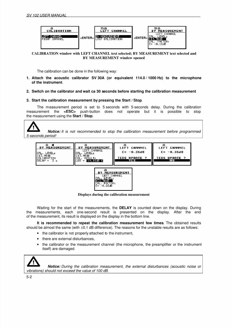
7/27/2019 SV_102 User Manual Chapters 1-9
http://slidepdf.com/reader/full/sv102-user-manual-chapters-1-9 46/113
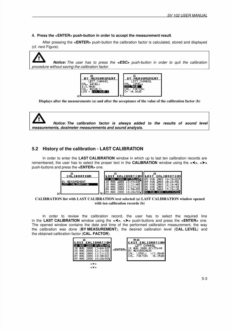
7/27/2019 SV_102 User Manual Chapters 1-9
http://slidepdf.com/reader/full/sv102-user-manual-chapters-1-9 47/113

7/27/2019 SV_102 User Manual Chapters 1-9
http://slidepdf.com/reader/full/sv102-user-manual-chapters-1-9 48/113
SV 102 USER MANUAL _
5-4
<ENTER>
Displays with LAST CALIBRATION records
In the case when the calibration measurements were not performed, the LAST CALIBRATION window does not contain any records. The contents of this window is cleared after the CLEAR SETUP operation (path: SETUP / CLEAR SETUP).
Empty LAST CALIBRATION window

7/27/2019 SV_102 User Manual Chapters 1-9
http://slidepdf.com/reader/full/sv102-user-manual-chapters-1-9 49/113

7/27/2019 SV_102 User Manual Chapters 1-9
http://slidepdf.com/reader/full/sv102-user-manual-chapters-1-9 50/113
SV 102 USER MANUAL .
6-2
Exemplary displays with not active sub-lists of INPUT list
6.1 Selection of measurement parameters - MEASUREMENT SETUP
The MEASUREMENT SETUP consists of the parameters, which can be set or switched on / off,namely the delay of the start of the measurements (START DELAY), the integration period(INTEGR. PERIOD), the repetition of the measurement cycles (REP. CYCLE) and the logger activationor deactivation (LOGGER). If the logger is active, the user can set the logging period (LOGGER STEP)and give a name to the logger’s file (LOGGER NAME).
<Shift>+<>
MEASUREMENT SETUP windows
6.1.1 Setting time delay before the start of measurements - START DELAY
The START DELAY defines the delay period from the pressing the Start / Stop to the startof the measurements (the digital filters of the instrument analyse constantly the input signal even when
the measurements are stopped). This delay period can be set from 0 second to 60 seconds.
<>
MEASUREMENT SETUP windows; the setting of START DELAY with 1-second step
Notice: The minimum delay period is equal to 0 second. In the case of CALIBRATION measurement, the delay period is equal to 5 seconds.
6.1.2 Setting the integration period - INTEGR. PERIOD
The INTEGR. PERIOD defines the period in which the signal is being averaged during the soundlevel measurements. The definitions of the measurement results in which the integration period is used isgiven in App. D.
The integration period (INTEGR. PERIOD) can be set
- From 1 s to 59 s (with 1-second step).

7/27/2019 SV_102 User Manual Chapters 1-9
http://slidepdf.com/reader/full/sv102-user-manual-chapters-1-9 51/113

7/27/2019 SV_102 User Manual Chapters 1-9
http://slidepdf.com/reader/full/sv102-user-manual-chapters-1-9 52/113

7/27/2019 SV_102 User Manual Chapters 1-9
http://slidepdf.com/reader/full/sv102-user-manual-chapters-1-9 53/113

7/27/2019 SV_102 User Manual Chapters 1-9
http://slidepdf.com/reader/full/sv102-user-manual-chapters-1-9 54/113

7/27/2019 SV_102 User Manual Chapters 1-9
http://slidepdf.com/reader/full/sv102-user-manual-chapters-1-9 55/113

7/27/2019 SV_102 User Manual Chapters 1-9
http://slidepdf.com/reader/full/sv102-user-manual-chapters-1-9 56/113

7/27/2019 SV_102 User Manual Chapters 1-9
http://slidepdf.com/reader/full/sv102-user-manual-chapters-1-9 57/113

7/27/2019 SV_102 User Manual Chapters 1-9
http://slidepdf.com/reader/full/sv102-user-manual-chapters-1-9 58/113

7/27/2019 SV_102 User Manual Chapters 1-9
http://slidepdf.com/reader/full/sv102-user-manual-chapters-1-9 59/113

7/27/2019 SV_102 User Manual Chapters 1-9
http://slidepdf.com/reader/full/sv102-user-manual-chapters-1-9 60/113
SV 102 USER MANUAL .
6-12
MEASURE TRIGGER window with SOURCE signal selection
Notice: In the LEVEL METER mode, only one signal measured in the instrument - the RMS detector of the first profile - can be used as the triggering signal. Additionally, the signal from I/O can be also used as the trigger source in the SLOPE + and SLOP – modes.
6.6.2.3 Setting the level of the triggering signal - LEVEL
The level of the triggering signal (LEVEL) can be set with 1-dB step from 24 dB to 136 dB range.
<>
MEASURE TRIGGER window with LEVEL selection in SLOPE + mode
6.6.2.4 Setting the speed of the triggering signal changes - GRADIENT
The speed of the triggering signal changes (GRADIENT) can be set with 1-dB/millisecond stepin the range from 1 dB/ms to 100 dB/ms.
<>
MEASURE TRIGGER window with GRADIENT selection (1 dB/ms)
6.6.3 Trigger parameters in logger setting - LOGGER TRIGGERThe LOGGER TRIGGER parameters influence the way the measurement results are saved
in the logger. The triggering in logger can be switched off or on ( TRIGGER) in a contexts sub-list.In the case when it is switched on, i.e. the LEVEL + mode - the source of the triggering signal isdetermined (SOURCE), its level can be selected (LEVEL), the number of the results savedin the logger before the fulfilment of the triggering condition (PRE) and the number of the results savedin the logger after the fulfilment of the triggering condition (POST). If the triggering signal is greater thanthe selected in the LEVEL, the logger contains:
• the measurement results registered directly before the fulfilment of the triggering condition; timeof the registration can be calculated by multiplying the value set in the PRE by the value taken fromthe LOGGER STEP (path: INPUT / MEASUREMENT SETUP / LOGGER STEP );

7/27/2019 SV_102 User Manual Chapters 1-9
http://slidepdf.com/reader/full/sv102-user-manual-chapters-1-9 61/113

7/27/2019 SV_102 User Manual Chapters 1-9
http://slidepdf.com/reader/full/sv102-user-manual-chapters-1-9 62/113
SV 102 USER MANUAL .
6-14
=>
<>
LOGGER TRIGGER windows with PRE selection
Time period of the measurements which are saved in the logger before the fulfilmentof the triggering condition can be calculated multiplying the value set in the PRE by the value setin the LOGGER STEP (path: INPUT / MEASUREMENT SETUP ). The result of the calculationis presented in the same line, at the right side of the display.
6.6.3.5 Selection of the number of the results to be saved in the logger after the fulfilment of thetriggering condition - POST
In the POST line, the number of the results registered in the logger’s file after the fulfilmentof the triggering condition can be set. This number is within the limits 0..200.
=>
<>
LOGGER TRIGGER windows with POST selection
Time period of the measurements which are saved in the logger after the fulfilment of the triggeringcondition can be calculated multiplying the value set in the POST by the value set in the LOGGER STEP
(path: INPUT / MEASUR. SETUP ). The result of the calculation is presented in the same line, at the right.
6.7 Selection of 1/1 octave spectrum parameters - SPECTRUM
The SPECTRUM appears in the INPUT window when the DOSE&1/1 OCTAVE orSLM&1/1 OCTAVE function is selected in the MEASUREMENT FUNCTION (path: FUNCTION / MEASUREMENT FUNCTION / DOSE & 1/1 OCTAVE or SLM & 1/1 OCTAVE ). The SPECTRUM consistsof the parameters, which influence the calculation and logging the results of 1/1 OCTAVE analysis:FILTER and LOGGER.
<ENTER>
SPECTRUM selected in INPUT window and SPECTRUM window opened
6.7.1 Selecting the weighting filter in 1/1 OCTAVE analysis - FILTER

7/27/2019 SV_102 User Manual Chapters 1-9
http://slidepdf.com/reader/full/sv102-user-manual-chapters-1-9 63/113

7/27/2019 SV_102 User Manual Chapters 1-9
http://slidepdf.com/reader/full/sv102-user-manual-chapters-1-9 64/113
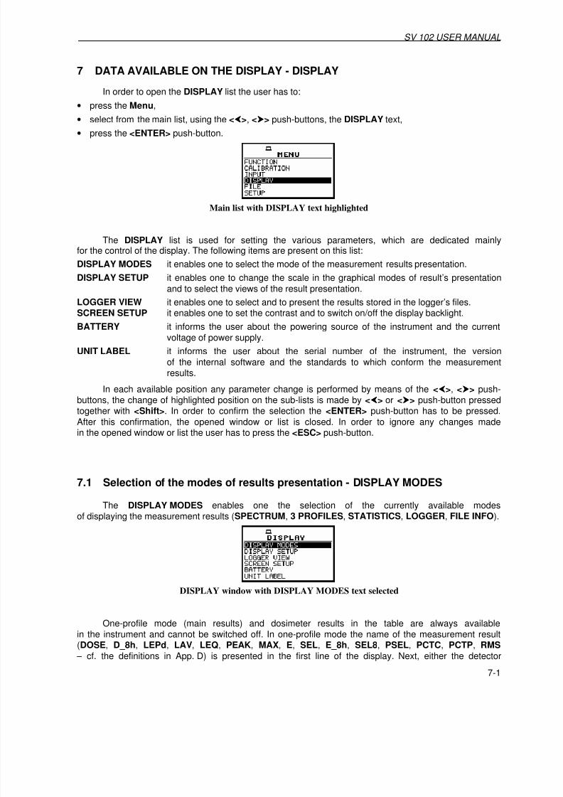
7/27/2019 SV_102 User Manual Chapters 1-9
http://slidepdf.com/reader/full/sv102-user-manual-chapters-1-9 65/113
SV 102 USER MANUAL
7-1
7 DATA AVAILABLE ON THE DISPLAY - DISPLAY
In order to open the DISPLAY list the user has to:
• press the Menu,
• select from the main list, using the <>, <> push-buttons, the DISPLAY text,
• press the <ENTER> push-button.
Main list with DISPLAY text highlighted
The DISPLAY list is used for setting the various parameters, which are dedicated mainlyfor the control of the display. The following items are present on this list:
DISPLAY MODES it enables one to select the mode of the measurement results presentation.
DISPLAY SETUP it enables one to change the scale in the graphical modes of result’s presentation
and to select the views of the result presentation.
LOGGER VIEW it enables one to select and to present the results stored in the logger’s files.SCREEN SETUP it enables one to set the contrast and to switch on/off the display backlight.
BATTERY it informs the user about the powering source of the instrument and the current
voltage of power supply.
UNIT LABEL it informs the user about the serial number of the instrument, the version
of the internal software and the standards to which conform the measurementresults.
In each available position any parameter change is performed by means of the <>, <> push-
buttons, the change of highlighted position on the sub-lists is made by <
> or <
> push-button pressedtogether with <Shift>. In order to confirm the selection the <ENTER> push-button has to be pressed.
After this confirmation, the opened window or list is closed. In order to ignore any changes madein the opened window or list the user has to press the <ESC> push-button.
7.1 Selection of the modes of results presentation - DISPLAY MODES
The DISPLAY MODES enables one the selection of the currently available modesof displaying the measurement results (SPECTRUM, 3 PROFILES, STATISTICS, LOGGER, FILE INFO).
DISPLAY window with DISPLAY MODES text selected
One-profile mode (main results) and dosimeter results in the table are always availablein the instrument and cannot be switched off. In one-profile mode the name of the measurement result(DOSE, D_8h, LEPd, LAV, LEQ, PEAK, MAX, E, SEL, E_8h, SEL8, PSEL, PCTC, PCTP, RMS
– cf. the definitions in App. D) is presented in the first line of the display. Next, either the detector

7/27/2019 SV_102 User Manual Chapters 1-9
http://slidepdf.com/reader/full/sv102-user-manual-chapters-1-9 66/113
SV 102 USER MANUAL .
7-2
(path: INPUT / PROFILE x / DETECTOR ) time constant (Fast, Slow or Impulse) is given for DOSE,D_8h, LAV, MAX results or indicator of linear RMS integration (Lin.) (when the RMS INTEGRATION isset to linear (path: SETUP / RMS INTEGRATION : LINEAR )) – in the case of LEPd, LEQ, E, SEL, E_8h,SEL8, PSEL, RMS results. There is not any indication of the detector in the case of PEAK, PCTC andPCTP results. The name of the implemented filter (path: INPUT / PROFILE x / FILTER ) is presented asthe last element of the first line (A, C or Z). The result of the measurement together with its unit is given
in the second line. The channel, the results are coming from, is visible in the bottom of the display(Ch: LEFT or Ch: RIGHT). The line showing the value of the result in the analogue-like form together
with the scale is presented at the left side of the display. The real time clock is visible in the bottom rightcorner of the display. The selection of the result is made by pressing the <>, <> push-buttons.If the measurement results are saved in the internal memory in a file or the AUTO SAVE option is
switched on, the name of the file is presented under the channel number. The same results as in the one-profile mode are presented in the table after double pressing <Shift> and <> push-buttons.
The PEAK, PCTC, PCTP, RMS results in one-profile mode are counted with C weighting filter. In the 3-profiles mode (in DOSE METER) Ltm3, Ltm5, Lxx, OVL, TIME, MIN and SPL values areadditionally presented.
The switch between available modes is made by pressing <Shift> together with <> or <> push-
button.
<Shift>+<>
<Shift>+<>
<Shift>+<> <Shift>+<> <Shift>+<>
<Shift>+<>
<Shift>+<>
Switching between all available presentation modes in one-channel mode
The results can be saved using AUTO SAVE, SAVE or SAVE NEXT functions after the endof the measurements caused by any reason (remote control, pressed Stop or fulfilmentof the INTEGR. PERIOD / REP. CYCLE condition). It is not possible to save the results duringthe execution of the measurements. In the case of using AUTO SAVE option, the name of the file to besaved is presented in the bottom line of one-profile mode during and after the measurement. In the caseof using SAVE or SAVE NEXT option the name of the file will appear on the display after execution
of the saving option.
Display after the end of the measurements with the file’s name the data are saved-in

7/27/2019 SV_102 User Manual Chapters 1-9
http://slidepdf.com/reader/full/sv102-user-manual-chapters-1-9 67/113

7/27/2019 SV_102 User Manual Chapters 1-9
http://slidepdf.com/reader/full/sv102-user-manual-chapters-1-9 68/113

7/27/2019 SV_102 User Manual Chapters 1-9
http://slidepdf.com/reader/full/sv102-user-manual-chapters-1-9 69/113

7/27/2019 SV_102 User Manual Chapters 1-9
http://slidepdf.com/reader/full/sv102-user-manual-chapters-1-9 70/113
SV 102 USER MANUAL .
7-6
Results presented in statistic presentation mode during the measurements
7.1.4 Setting on/off logger view - LOGGER
The possibility of the presentation of the measurement results, which are saved in the logger,on the instrument’s display can be switched on or off placing or replacing the special characterin the highlighted line with the LOGGER text.
Setting on and off the possibility of presentation the results saved in the logger
The results saved in the logger can be presented in three different modes, which differ slightly each
other. These modes can be set in the VIEW (path: DISPLAY / DISPLAY SETUP / LOGGER VIEW / VIEW ).
Different presentation modes of the results stored in logger (extended, full, normal)
7.1.5 Setting on/off the view of the file description - FILE INFOThe possibility of the additional file description presented on the instrument’s display can
be switched on or off placing or replacing the special character in the highlighted linewith the FILE INFO text.
Setting on and off the logger’s file description presentation mode
In the FILE INFO window, the following parameters are presented: the file name, its size, date andtime of the registration of the main results (cf. App. B) and time (ELAPSED TIME ) during which the mainresults saved in the logger were measured. The value presented there belongs to the range[1, INTEGRATION PERIOD] and depends on the moment and the way the measurements were stopped.
Exemplary contents of FILE INFO window

7/27/2019 SV_102 User Manual Chapters 1-9
http://slidepdf.com/reader/full/sv102-user-manual-chapters-1-9 71/113

7/27/2019 SV_102 User Manual Chapters 1-9
http://slidepdf.com/reader/full/sv102-user-manual-chapters-1-9 72/113
SV 102 USER MANUAL .
7-8
Results stored in logger presented with different DYNAMIC (160 dB, 80 dB, 40 dB, 20 dB, 10 dB)
7.2.1.2 Switching on/off the grid in graphical presentation - GRID
The GRID enables the user to switch on or off the grid in any graphical presentation placing orreplacing the special character in the highlighted line with the GRID text.
DISPLAY SCALE windows with the grid switched on and off
Displays with the grid switched on and off
7.2.2 Setting main results view - MAIN VIEWIn the MAIN VIEW it is possible to select NORMAL or LARGE view of the main results
in the one profile mode.
DISPLAY SETUP window, the MAIN VIEW text selected
MAIN VIEW window, VIEW selection

7/27/2019 SV_102 User Manual Chapters 1-9
http://slidepdf.com/reader/full/sv102-user-manual-chapters-1-9 73/113

7/27/2019 SV_102 User Manual Chapters 1-9
http://slidepdf.com/reader/full/sv102-user-manual-chapters-1-9 74/113
SV 102 USER MANUAL .
7-10
STATISTICS presentation mode, NORMAL VIEW and EXTENDED VIEW
7.2.5 Setting the parameters of logger files presentation - SPECTRUM VIEW
The SPECTRUM VIEW appears on the DISPLAY SETUP list in the case of DOSE&1/1 OCTAVE or SLM&1/1 OCTAVE analysis modes and enables the user to change TYPE parameter as well asto activate the presentation on the display the MAX and MIN spectrum.
DISPLAY SETUP window with SPECTRUM VIEW text highlighted
7.2.5.1 Selection of spectrum type for the presentation - TYPE
In the TYPE, the AVERAGED, INSTANTANEOUS, MAX and MIN options are available.
Each text corresponds to the different spectrum type to be presented on the display in the graphicalpresentation modes.
SPECTRUM VIEW windows with TYPE selection
7.2.5.2 Selection of MAX spectrum for the presentation - MAX
In the MAX, the corresponding spectrum can be selected to the presentation on the display
in the graphical modes.
SPECTRUM VIEW windows with MAX spectrum selection
7.2.5.3 Selection of MIN spectrum for the presentation - MIN
In the MIN, the corresponding spectrum can be selected to the presentation on the display
in the graphical modes.
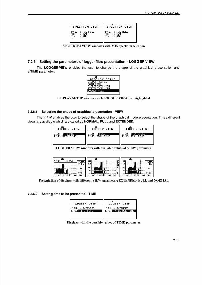
7/27/2019 SV_102 User Manual Chapters 1-9
http://slidepdf.com/reader/full/sv102-user-manual-chapters-1-9 75/113

7/27/2019 SV_102 User Manual Chapters 1-9
http://slidepdf.com/reader/full/sv102-user-manual-chapters-1-9 76/113

7/27/2019 SV_102 User Manual Chapters 1-9
http://slidepdf.com/reader/full/sv102-user-manual-chapters-1-9 77/113

7/27/2019 SV_102 User Manual Chapters 1-9
http://slidepdf.com/reader/full/sv102-user-manual-chapters-1-9 78/113

7/27/2019 SV_102 User Manual Chapters 1-9
http://slidepdf.com/reader/full/sv102-user-manual-chapters-1-9 79/113
SV 102 USER MANUAL
7-15
7.5 Checking the state of internal battery - BATTERY
The BATTERY enables the user to check the internal battery condition.
The instrument can be powered from four AA standard or rechargeable batteries or from the USBinterface when its USB Device socket is connected by means of the cable to a PC. The view presented
on the display in each case is different. The current battery voltage is displayed together withits approximate state (in the graphical form).
<ENTER>
DISPLAY window with BATTERY selected and BATTERY windows for different powering sources
7.6 Checking specification of the instrument - UNIT LABEL
The UNIT LABEL enables the user to check the type of the instrument, its serial number,the current software versions installed in it and the standards, which the instrument fulfils.
DISPLAY window with UNIT LABEL text highlighted
After pressing the <>, <> push-buttons the displayed text is scrolled on the display and
the user can check the number of the standard fulfilled by the instrument and the current software version.
<>..<>
<>..<>
UNIT LABEL windows opened and scrolled with the <>, <> push-buttons
Notice: The contents of the UNIT LABEL should be always transmitted to the Svantek’s service in the case of any problems faced by the user during the instrument’s operation.

7/27/2019 SV_102 User Manual Chapters 1-9
http://slidepdf.com/reader/full/sv102-user-manual-chapters-1-9 80/113

7/27/2019 SV_102 User Manual Chapters 1-9
http://slidepdf.com/reader/full/sv102-user-manual-chapters-1-9 81/113

7/27/2019 SV_102 User Manual Chapters 1-9
http://slidepdf.com/reader/full/sv102-user-manual-chapters-1-9 82/113
SV 102 USER MANUAL _
8-2
Main list; FILE text highlighted
The FILE list (window) contains the following items:
SAVE it enables one to save the measurement results as a file in the instrument’s
memory.
SAVE OPTIONS it enables one to set the options of the measurement result savings.
LOAD it enables one to load the measurement results saved in a file.
DELETE it enables one to delete a selected file from the instrument’s memory.
DELETE ALL it enables one to delete all files from the instrument’s memory.
DEFRAGMENTATION it enables one to consolidate the flash memory after deleting some files from it.
CATALOGUE it enables one to overview the catalogue of the files saved in the instrument’smemory.
FREE SPACE it informs the user about the capacity of the instrument’s memory still available
for storing the measurement results.
SAVE SETUP it enables one to save the setup as a file in the instrument memory.
LOAD SETUP it enables one to load to the working space of the instrument’s memory
the selected setup saved in a file.
FILE window
The parameter selection on the sub-list is performed by means of the <>, <> push-buttons.The selection of the position on the sub-list is made with <>, <> push-buttons pressed togetherwith <Shift>. In order to confirm the selection the <ENTER> push-button has to be pressed.After this confirmation, the opened window or list is closed. In order to ignore any changes madein the opened window or list the user has to press the <ESC> push-button.
In the case when the measurement is performed, the usage of the options from the FILE list isimpossible (only access to CATALOGUE and SAVE OPTION is still possible) and the special message
appears on the display.
Display after the attempt to perform an unavailable operation during measurement in progress

7/27/2019 SV_102 User Manual Chapters 1-9
http://slidepdf.com/reader/full/sv102-user-manual-chapters-1-9 83/113
SV 102 USER MANUAL
8-3
8.1 Saving files in the instrument’s memory - SAVE and SAVE NEXT
The SAVE is used for storing data in the internal non-volatile (FLASH DISC) memory
(files are always written at the beginning of a free continuous space) as a file (see Appendix B for the fileformats). The SAVE window is opened also by pressing <> and <ENTER> push-buttons simultaneously
after measurement.
There are two available functions: the SAVE NEXT – save a file with the name increased by oneand SAVE – save a file with the edited name.
<ENTER>
<>
<Shift>+<>
Saving a file using SAVE option
The name edition is made with <>, <> and <Shift> push-buttons. To enter FILE NAME linepress <Shift> and <> push-buttons together. The default name consists of the day and the month’s
abbreviation (e.g. 09OCT).
The user can skip the file’s name edition and start saving file by pressing the <ENTER> push-button or return to the FILE list (or main results view) by pressing the <ESC> one.
The edition process is presented on the Figure below. The displayed highlighted character
is currently edited. The name cannot be longer than eight characters. One can select the proper positionof the cursor in the edited text using the <Shift> and <> push-buttons. The character selection is madewith <>, <> push-buttons.
<Shift>+<>
Display during the selection of the character’s position to be edited
<>
Display during the selection of the character
The edited name is accepted and the file is saved after pressing the <ENTER> push-button.
The special warning is displayed in the case the file with the edited name already exists in the memory.The instrument waits then for a reaction of the user (any push-button should be pressed exceptthe <Shift>).

7/27/2019 SV_102 User Manual Chapters 1-9
http://slidepdf.com/reader/full/sv102-user-manual-chapters-1-9 84/113

7/27/2019 SV_102 User Manual Chapters 1-9
http://slidepdf.com/reader/full/sv102-user-manual-chapters-1-9 85/113
SV 102 USER MANUAL
8-5
the name, which was used before. The instrument displays a special message and waits forthe reaction of the user (any push-button should be pressed except the <Shift>) and after pressinga push-button it returns to the FILE list.
Displays after the attempt to overwrite a file if the REPLACE is not active
Notice: The logger files are created automatically (the usage of the SAVE is not required).
8.2 Controlling the data storing in the instrument’s memory - SAVE OPTIONS
The SAVE OPTIONS is used for the selection of the options of data storing in the flash memory
of the instrument.
FILE window with SAVE OPTIONS text highlighted
It is possible to write data into the same part of the memory starting all the time with the sameaddress (RAM FILE), to replace the existing in the memory file by the new with the same name(REPLACE), to add to the results the statistics of the measurements (SAVE STATISTICS), to saveautomatically the results of the measurements (AUTO SAVE).
8.2.1 Saving data starting from the same address - RAM FILE
The RAM FILE functionality is available only in the SLM and SLM&1/1 OCTAVE analysis modes.
The measurement data usually are saved in the different files in the flash memory of the instrument.
It means that each time the data are saved the previous file is overwritten.
This option is useful for the permanent monitoring and remote reading data from the instrumentby means of any available interface with the proper period. In order to read data saved in a RAM file onehas to use #4,3 function described in details in App. A.
<>
SAVE OPTIONS window; selection of RAM FILE in SLM modes

7/27/2019 SV_102 User Manual Chapters 1-9
http://slidepdf.com/reader/full/sv102-user-manual-chapters-1-9 86/113

7/27/2019 SV_102 User Manual Chapters 1-9
http://slidepdf.com/reader/full/sv102-user-manual-chapters-1-9 87/113

7/27/2019 SV_102 User Manual Chapters 1-9
http://slidepdf.com/reader/full/sv102-user-manual-chapters-1-9 88/113

7/27/2019 SV_102 User Manual Chapters 1-9
http://slidepdf.com/reader/full/sv102-user-manual-chapters-1-9 89/113
SV 102 USER MANUAL
8-9
Notice: The logger file can be deleted from the instrument’s memory in the FILE / DELETE / LOGGER FILES window and this deleting operation does not modify the contents of the fourth line of the LOAD window.
Notice: Many result files can be associated with one logger file, i.e. during the execution of the AUTO SAVE function.
<>
<>
Exemplary result files associated with the same logger file (&LOG99)
The contents of the loaded file is displayed in the available result presentation modes(after pressing the <Shift> and <> push-buttons) depending on the current settings of the instrument.
Exemplary displays during the loading and checking the contents of a DOSE METER file
In the case when in the DISPLAY MODES window the STATISTICS are activatedand in the loaded file the statistic analysis was not included the display with NO RESULT messageis presented in the graphical presentation of the statistical levels.
8.4 Removing a file with the measurement results from memory - DELETE
The DELETE is used to remove a file from memory.
<ENTER>
<ENTER> <>

7/27/2019 SV_102 User Manual Chapters 1-9
http://slidepdf.com/reader/full/sv102-user-manual-chapters-1-9 90/113
SV 102 USER MANUAL _
8-10
<ENTER>
Deleting a file
In the DELETE window, there are three elements: RESULT FILES, LOGGER FILES and SETUP FILES. The deleting of those three types of files is performed in the same way as shown
above.
In the case when there are no files in the memory, the NO FILES message appears on the display.
RESULT FILES selected to be deleted and the flash memory does not contain any file
The same data about the existing in the instrument files as in the FILE / LOAD windoware displayed after successful opening the FILE / DELETE / RESULT FILES one (pressing the <ENTER>
push-button, see part 8.3).
In the case of LOGGER FILES, the data in the DELETE window are similar as in the DISPLAY /LOGGER VIEW window. In the first line, the available still logger’s memory is displayed followed by:
• The selected number of the logger’s file and the number of all saved files ( FILE NO.).
• The name of the logger’s file (LOG.FILE).
• The size of the logger file which name is displayed in the previous line (LOG.SIZE).
• The results saved (if any are present) in the logger from the first, second and third profile of the leftchannel (P1L, P2L, P3L), from the first, second and third profile of the right channel ( P1R, P2R, P3R),from the third profile.
<>
Selection of LOGGER FILE to be deleted
Notice: The logger file can be deleted from the instrument’s memory in the FILE / DELETE / LOGGER FILES window and this deleting operation does not modify the contents of the fourth line of the DELETE window.
In the case of SETUP FILES, the current number of the file and the total number of the saved setupfiles is displayed in the first line of the window. The FILE NAME is presented in the second line. The dateand time of the SAVE SETUP operation is displayed in the last two lines respectively.

7/27/2019 SV_102 User Manual Chapters 1-9
http://slidepdf.com/reader/full/sv102-user-manual-chapters-1-9 91/113
SV 102 USER MANUAL
8-11
SETUP file selected to be deleted
After the execution of the result files and setup files removing from the memory usuallythe FREE SPACE memory (path: FILE / FREE SPACE ) rests the same as before the deletion butTOTAL AVAILABLE memory is increased. It is because erased file was somewhere in the file’s space.
The file is no longer accessible but the recuperated memory is still unused for the next saving.This memory becomes available after the defragmentation process (path: FILE / DEFRAGMENTATION)in which all files are moved to the continuous space.
After the execution of the logger files deletion from the memory, usually the logger free space reststhe same as before the deletion but the total logger available memory is increased. It is because erasedfile was somewhere in the file’s space. The file is no longer accessible but the recuperated memory is still
unused for the next saving. This memory becomes available after the defragmentation process(path: FILE / DEFRAGMENTATION / LOGGER DEFRAGMENT .) in which all files are movedto the continuous space.
<ENTER>
Execution of the @SET3 file deletion
=>
Influence of the execution of the @SET3 file deletion on the memory space
The displays below illustrates the erasing from the flash memory another file named @SET4;the FILES FREE SPACE, LOGGER FREE SPACE and LOGGER AVAILABLE remain unchanged whilethe TOTAL AVAILABLE is increased.
=>
=>
Execution of the @SET4 file deletion and the influence of this process on the memory space

7/27/2019 SV_102 User Manual Chapters 1-9
http://slidepdf.com/reader/full/sv102-user-manual-chapters-1-9 92/113
SV 102 USER MANUAL _
8-12
8.5 Removing all files with measurement results from memory - DELETE ALL
The DELETE ALL is used to remove all files from memory. The DELETE ALL consists of threepositions: RESULT FILES, LOGGER FILES and SETUP FILES. The deleting of those three types of files
is performed in the same way (shown below). In order to delete all result, logger or setup files the user hasto select type (types) of files to be deleted, press <ENTER>, confirm the selection and press <ENTER>
again.
<ENTER>
<> <ENTER>
<>
<ENTER>
Deleting all files
Notice: The execution of the DELETE ALL function described above takes place in the case
when only one type of the files is selected in the DELETE ALL window. If all types are selected simultaneously and the logger, result and setup are saved, only Clearing operation is performed but two times – one time in logger files memory and one time in result and setup files memory. After clearing all memory, the defragmentation is not done. The memory merging is done only in the case of setup and results memory, as these two different types of files are saved together in the same space.
8.6 Merging file space - DEFRAGMENTATION
The DEFRAGMENTATION is used to make the file memory continuous. All new files are saved
starting from the beginning of the free memory space. The memory occupied by the deleted file, assuming
that the file was not the last one, remains unused for the next files saving. After the removinga file the files memory becomes discontinuous, with unused parts, which cannot be utilized in the future.The situation is changed after the process called defragmentation. During this process, the files savedin the files memory are moved in order to obtain the continuous occupied space.
The files’ merging is performed separately for two parts of the instrument’s memory:the FILES DEFRAGMENT. is used to join the result and setup files and LOGGER DEFRAGMENT. is used in the case of the logger. Before the defragmentation the FILES FREE SPACE andTOTAL AVAILABLE, characterizing the result memory (path: FILE / FREE SPACE ), usually differ
between each other. After this operation, these two parts are equal. The same situation is in the caseof the LOGGER FREE SPACE and TOTAL AVAILABLE characterizing the logger file.

7/27/2019 SV_102 User Manual Chapters 1-9
http://slidepdf.com/reader/full/sv102-user-manual-chapters-1-9 93/113
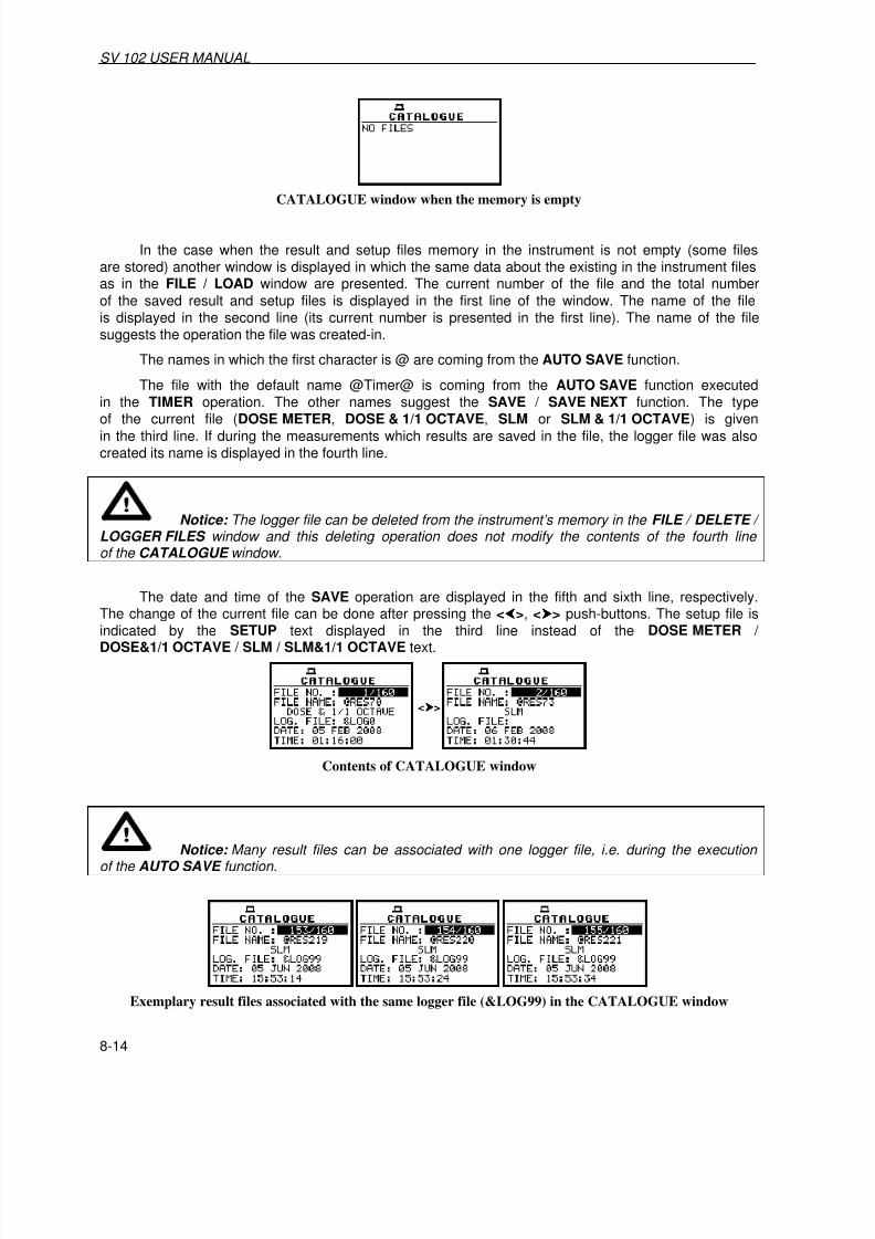
7/27/2019 SV_102 User Manual Chapters 1-9
http://slidepdf.com/reader/full/sv102-user-manual-chapters-1-9 94/113
SV 102 USER MANUAL _
8-14
CATALOGUE window when the memory is empty
In the case when the result and setup files memory in the instrument is not empty (some filesare stored) another window is displayed in which the same data about the existing in the instrument filesas in the FILE / LOAD window are presented. The current number of the file and the total number
of the saved result and setup files is displayed in the first line of the window. The name of the fileis displayed in the second line (its current number is presented in the first line). The name of the filesuggests the operation the file was created-in.
The names in which the first character is @ are coming from the AUTO SAVE function.
The file with the default name @Timer@ is coming from the AUTO SAVE function executedin the TIMER operation. The other names suggest the SAVE / SAVE NEXT function. The type
of the current file (DOSE METER, DOSE & 1/1 OCTAVE, SLM or SLM & 1/1 OCTAVE) is givenin the third line. If during the measurements which results are saved in the file, the logger file was alsocreated its name is displayed in the fourth line.
Notice: The logger file can be deleted from the instrument’s memory in the FILE / DELETE / LOGGER FILES window and this deleting operation does not modify the contents of the fourth line of the CATALOGUE window.
The date and time of the SAVE operation are displayed in the fifth and sixth line, respectively.The change of the current file can be done after pressing the <>, <> push-buttons. The setup file is
indicated by the SETUP text displayed in the third line instead of the DOSE METER / DOSE&1/1 OCTAVE / SLM / SLM&1/1 OCTAVE text.
<>
Contents of CATALOGUE window
Notice: Many result files can be associated with one logger file, i.e. during the execution of the AUTO SAVE function.
Exemplary result files associated with the same logger file (&LOG99) in the CATALOGUE window

7/27/2019 SV_102 User Manual Chapters 1-9
http://slidepdf.com/reader/full/sv102-user-manual-chapters-1-9 95/113

7/27/2019 SV_102 User Manual Chapters 1-9
http://slidepdf.com/reader/full/sv102-user-manual-chapters-1-9 96/113
SV 102 USER MANUAL _
8-16
The SAVE SETUP is used for storing setup settings in the internal non-volatile (FLASH DISC)
memory (files are always written at the beginning of a free continuous space) as a file (see Appendix B forthe file formats).
SAVE SETUP text highlighted in FILE window
There are two available functions: the SAVE NEXT – save a setup file with the name increasedby one, and SAVE – save a setup file with the edited name.
<ENTER>
Saving SETUP using SAVE NEXT option
<>
SAVE SETUP window, SAVE option selection
The default file name for setup settings is SET. To edit FILE NAME press <Shift> and <>.
The user can skip the setup file’s name edition and start saving file pressing the <ENTER> push-button or return to the FILE window pressing the <ESC> one.
The edition process is presented on the Figure below. The highlighted character is edited with <>,<> push-buttons. The name cannot exceed eight characters.
<>
Display during the process of setting the character in the edited name
One can select the proper character’s position in the edited text using the <>, <> push-buttons.
<Shift> and <>
Display during the selection of the character’s position to be edited

7/27/2019 SV_102 User Manual Chapters 1-9
http://slidepdf.com/reader/full/sv102-user-manual-chapters-1-9 97/113
SV 102 USER MANUAL
8-17
The edited name is accepted and the setup file is saved after pressing the <ENTER> push-button.
The special warning is displayed in the case the file with the edited name already exists in the memory,if the REPLACE is not activated (path: FILE / SAVE OPTIONS ). The instrument waits then for a reactionof the user (any push-button should be pressed except the <Shift>).
All changes introduced to the setup file name during the edition are ignored after pressing
the <ESC> push-button. This pressing causes the return to the list from which the SAVE optionwas entered. The return after the edition to the line with the SAVE or SAVE NEXT text is possibleafter pressing the <Shift> and <> push-buttons.
The simplified edition consists in the addition at the end of the file name the natural number.The increase by one of the number is made automatically. After the saving operation execution the newsetup file name is displayed and the instrument waits then for a reaction of the user (any push-buttonshould be pressed except the <Shift>).
=>
...
<ENTER>
<ANY KEY>
Displays during the attempt of overwriting the existing file, changing the name and saving data
In the next attempt of saving data, the new name is displayed in the FILE NAME line and that name
is increased by one during the saving operation.
...
...
Saving SETUP file using SAVE NEXT option
The number can be changed from 1 to 999999. In the case when such limitation is achieved andthe instrument can not change automatically the file’s name the only possibility is to edit new base filename.
Notice: The files can be overwritten (the use of the same file name) without any warning if the REPLACE option is switched on (path: FILE / SAVE OPTIONS / REPLACE).

7/27/2019 SV_102 User Manual Chapters 1-9
http://slidepdf.com/reader/full/sv102-user-manual-chapters-1-9 98/113
SV 102 USER MANUAL _
8-18
<ENTER>
Saving setup with SAVE NEXT option and the message in the case when the file already exists
Notice: During the execution of the SAVE or SAVE NEXT function an additional window is displayed informing about the operation performed. This window can be unnoticed by the user as it appears for the short time.
<ENTER>
Displays during and after the execution of the SAVE operation
As it was already written, it is not possible to store the data in the file, which already exists, whenthe REPLACE is not active ([ ]) (path: FILE / SAVE OPTIONS / REPLACE ).
The presented below sequence of displays illustrates the situation when during the name-editionprocess, the user selected the name that was used before but this time the REPLACE is active. The setup
file is overwritten, the instrument displays a special message and waits for the reaction of the user(any push-button should be pressed except the <Shift> and after pressing a push-button it returnsto the FILE window.
<ENTER>
... =>
=> ...
<ENTER> <ANY KEY>
Displays after the attempt to overwrite a file if REPLACE is active
8.10 Loading the files with the setup settings - LOAD SETUP
The LOAD SETUP is used for loading setup setting file from the FLASH DISC (e.g. for performingdifferent type of measurements with different instrument’s settings). It is possible to load FILE SETUPor STANDARD SETUP.

7/27/2019 SV_102 User Manual Chapters 1-9
http://slidepdf.com/reader/full/sv102-user-manual-chapters-1-9 99/113
SV 102 USER MANUAL
8-19
<ENTER> <>
FILE window with LOAD SETUP text highlighted and LOAD SETUP window with available options
8.10.1 Loading setup file - FILE SETUP
In the FILE SETUP window, the user can select setups saved previously by SAVE SETUP option(path : FILE / SAVE SETUP ).
<ENTER> <>
FILE SETUP window; selection the file for loading
Notice: It is not possible to load the file during the execution of the measurements. On such attempt the message: MEASUREMENT IN PROGRESS is displayed for about 3 seconds.
In the case when the setup files were not saved, after entering the LOAD SETUP window,the NO FILES text is displayed and the instrument waits for the reaction of the user. The user shouldpress then the <ESC>, <ENTER> (the instrument returns to the FILE window) or Start / Stop push-button(the instrument starts the measurement).
Display during the execution of LOAD SETUP operation
The current number of the setup file and the total number of the saved setup files is displayedin the first line of the LOAD SETUP window. The name of the file is displayed in the second line(its current number is presented in the first line). The date and time of the SAVE SETUP operation isdisplayed in the fourth and fifth line respectively.
8.10.2 Standard setup loading - STANDARD SETUP
In the STANDARD SETUP, it is possible to select one of the standard setups and load it. Availablesetups are as follows: OSHA, MSHA, DOD, ACGIH, ISO 85, ISO 90. The settings of the setups arepresented below. Other settings are the same as after the CLEAR SETUP operation.

7/27/2019 SV_102 User Manual Chapters 1-9
http://slidepdf.com/reader/full/sv102-user-manual-chapters-1-9 100/113
SV 102 USER MANUAL _
8-20
OSHA MSHA DOD ACGIH ISO 85 ISO 90
Detector Slow Slow Slow Slow Fast Fast
Filter (firstprofile)
A A A A A A
Exchangerate 3 3 3 3 3 3
ThresholdLevel
80 dB 80 dB 80 dB 80 dB 70 dB 70 dB
CriterionLevel
90 dB 90 dB 85 dB 85 dB 85 dB 90 dB
STANDARD SETUPS parameters
<ENTER>
STANDARD SETUP loading

7/27/2019 SV_102 User Manual Chapters 1-9
http://slidepdf.com/reader/full/sv102-user-manual-chapters-1-9 101/113
SV 102 USER MANUAL
9-1
9 SETUP MENU - SETUP
The SETUP list (window) contains different elements. Some of them are directly related with
dose/sound measurements and some - with the settings of the hardware components of the instrument.
In order to open the SETUP list the user has to:
• press the Menu,• select from the main list, using the <>, <> push-buttons, the SETUP text (highlight it),
• press the <ENTER> push-button.
Display in the main list; SETUP text highlighted
In the SETUP list, the following items are available:LANGUAGE it enables the user to set language of the user interface.
CLEAR SETUP it enables the user to return to the default, factory setup.
DAY TIME LIMITS it enables the user to select the hours limiting day and night for the calculationof the Lden result.
EXPOSURE TIME it enables the user to define the exposure time used for the LEPd measurementand other DOSE METER results.
EXTERNAL I/O SETUP it enables the user to select the available functionality of the Ext. I/O port.
KEYBOARD it enables the user to switch on/off the KEY LOCK and to set the operatingmode of the <Shift> push-button.
MICROPHONE it enables the user to set on or off the compensation filter.
RMS INTEGRATION it enables the user to select the way of integration for the “family”of the LEQ measurements.
RTC it enables the user to set the Real Time Clock of the instrument.
STATISTICAL LEVELS it enables the user to select ten statistic levels to be saved in the fileswith the main results.
TIMER it enables the user to set the Timer function.
WARNINGS it enables the user to switch on or off the warnings that can be displayed during
the operation of the instrument.
In each available position any change is performed by means of the <>, <> push-buttons or<>, <> push-buttons pressed together with <Shift>. In order to confirm the selection the <ENTER>
push-button has to be pressed. After this confirmation, the opened window or list is closed. In orderto ignore any changes made in the opened window or list the user has to press the <ESC> push-button.
SETUP list of the instrument

7/27/2019 SV_102 User Manual Chapters 1-9
http://slidepdf.com/reader/full/sv102-user-manual-chapters-1-9 102/113

7/27/2019 SV_102 User Manual Chapters 1-9
http://slidepdf.com/reader/full/sv102-user-manual-chapters-1-9 103/113

7/27/2019 SV_102 User Manual Chapters 1-9
http://slidepdf.com/reader/full/sv102-user-manual-chapters-1-9 104/113
SV 102 USER MANUAL .
9-4
9.5 Available parameters of the Ext. I/O port selection - EXTERNAL I/O SETUP
The EXTERNAL I/O SETUP enables the user to select the available functionality of the extendedI/O port. Next, the user should select proper channel to made EXT. I/O settings.
<ENTER> <>
SETUP list with EXTERNAL I/O SETUP text highlighted and channel selection in EXT. I/O SETUP window
9.5.1 Mode selection of the Ext. I/O port - MODE
In the MODE, it is possible to select the function of the instrument’s socket named as Ext. I/O.This socket can be used as
•The output of the analogue signal (ANALOG OUT) transmitted from the input of the instrument to itsoutput without any digital processing (i.e. filtering).
• The input of the digital signal used as an external trigger to start the measurements ( DIGITAL IN)in the “slave” instrument; (this mode is available for RIGHT CHANNEL).
• The digital output (DIGITAL OUT) used for triggering other “slave” instrument from the “master” one(this mode is available for LEFT CHANNEL).
• The source of any alarm signal in the case of certain circumstances occurred duringthe measurements (i.e. the level of the input signal was higher than selected one).
The more detailed description of the Ext. I/O is given in App. C.
a)
b)
EXTERNAL I/O SETUP windows; MODE selection in LEFT CHANNEL (a) and RIGHT CHANNEL (b)
In the case of DIGITAL IN (RIGHT CHANNEL) selection the signal appearing on the Ext. I/O socket will be treated as the external trigger if the EXT. I/O is chosen (path: INPUT / TRIGGER SETUP / MEASURE TRIGGER / SOURCE / EXT. I/O ) and it can be set only if SLOPE + or SLOPE – was setas a TRIGGER (path: INPUT / TRIGGER SETUP / MEASURE TRIGGER / TRIGGER ).
<>
MEASURE TRIGGER windows; SOURCE selection

7/27/2019 SV_102 User Manual Chapters 1-9
http://slidepdf.com/reader/full/sv102-user-manual-chapters-1-9 105/113

7/27/2019 SV_102 User Manual Chapters 1-9
http://slidepdf.com/reader/full/sv102-user-manual-chapters-1-9 106/113
SV 102 USER MANUAL .
9-6
9.5.6 Alarm level selection on the digital output of Ext. I/O - ALARM LEVEL
In the ALARM LEVEL, it is possible to set the level of the result to be monitored duringthe measurements. If the result is greater than the one set in this line, the instrument will generatethe alarm signal in the selected logic. The available levels are within the range [30.0 dB, 140 dB] and canbe decreased / increased with 0.1 dB step.
<>
EXTERNAL I/O SETUP windows; ALARM LEVEL setting
9.6 Selection of keyboard settings - KEYBOARD
In the KEYBOARD, it is possible to switch on the key lock and to select the <Shift> push-buttonworking mode.
SETUP window with KEYBOARD text highlighted
9.6.1 Switching the key lock on - KEY LOCK
The KEY LOCK is switched on after selecting On in the KEY LOCK position.
<>
KEYBOARD windows; available KEY LOCK settings
After setting KEY LOCK to On the user can still make settings in the instrument. Whenthe measurement starts the KEYBOARD LOCKED message appears on the display and the accessto the MENU window is locked. The results will be saved automatically. After the measurement, theaccess to the files by instrument interface is denied. It is also not possible to LOAD SETUP orDELETE SETUP. In order to get access to the files the user has to download the files from the instrumentto a PC using SvanPC+. The KEY LOCK may be switched off after the measurement, but the access tothe files will be unlocked only after downloading the files to a PC.
Display after the beginning of measurement when the Key lock is ON

7/27/2019 SV_102 User Manual Chapters 1-9
http://slidepdf.com/reader/full/sv102-user-manual-chapters-1-9 107/113

7/27/2019 SV_102 User Manual Chapters 1-9
http://slidepdf.com/reader/full/sv102-user-manual-chapters-1-9 108/113
SV 102 USER MANUAL .
9-8
<ENTER> <>
SETUP window with RMS INTEGRATION text highlighted and displays with the available options of RMSINTEGRATION
The formulae used for the LEQ calculation are given in Appendix D. Setting LINEAR is requiredfor getting the true RMS value of the measured signal. When this option is selected the value of the LEQ,Lden, LEPd, Lxx and SEL functions do not depend on the detector time constant: Fast, Slow or Impulse (the results are displayed without the indicator of the detectors selected in the profiles). In this case,the indicator Lin. (or L) is displayed in different modes of measurement results presentation. SettingEXPONENTIAL enables the user to fulfil the requirements of another standard for the LEQ measurements. When this option is selected the value of the LEQ, Lden, LEPd, Lxx and SEL functiondepends on the detector time constant (the results are displayed with the indicator of the detectorsselected in the profiles (path: INPUT / PROFILE x / DETECTOR: Fast, Slow or Impulse ).
9.9 Programming the instrument’s internal Real Time Clock - RTC
The RTC (Real Time Clock) enables one to programme the time and date in the instrument.
SETUP window with RTC text highlighted
The selection of the setting parameter (hour, minute, second, day, month and year) is performedusing the <>, <> push-buttons and the change of its value – using the <>, <> push-buttons pressedtogether with the <Shift>.
<>
<Shift>+<>
RTC windows with the time selection
Notice: The new value of a parameter is confirmed after each pressing of the <> or <> together with the <Shift> push-buttons (new value is selected without any confirmation from the <ENTER> push-button).

7/27/2019 SV_102 User Manual Chapters 1-9
http://slidepdf.com/reader/full/sv102-user-manual-chapters-1-9 109/113
SV 102 USER MANUAL
9-9
Notice: The RTC window will appear on the display after power on when the RTC settings were lost, i.e. in the case of long lack of power source (batteries or USB interface). In such a case the work of RTC will be held up for minimum 1 hour.
9.10 Setting ten statistical levels - STATISTICAL LEVELS
In the STATISTICAL LEVELS, it is possible to select which ten statistical levels, named from N1 toN10, has to be calculated and saved in the files together with the main results.
SETUP window with STATISTICAL LEVELS text selected
The default statistical levels have the following settings: 1, 10, 20, 30, 40, 50, 60, 70, 80 and 90.All values have to be within the range [1, 99]. Each one value can be set independently from the others.The selection of the Nx is made using the <> or <> push-button pressed together with <Shift>.The upper Nx visible on the display is active after pressing the <> together with the <Shift> push-button.The lower Nx visible on the display is active after pressing the <> together with the <Shift> push-button.The Nx current value decreasing / increasing by one is possible by means of the <> / <> push-buttons.
<> ...
<Shift>+<>
STATISTICAL LEVELS windows
The selected values of the statistical levels are visible in 3 profiles mode (DOSE METER mode).The selection of the statistical level is made by pressing <ESC> push-button (<Shift> and <ENTER>).
In the SLM mode the view and selection of statistical levels is also available in one profile mode.
<Shift> + <ENTER>
Selection of statistical level (results) in 3 PROFILE mode

7/27/2019 SV_102 User Manual Chapters 1-9
http://slidepdf.com/reader/full/sv102-user-manual-chapters-1-9 110/113
SV 102 USER MANUAL .
9-10
<Shift> + <ENTER>
Selection of statistical level (results) in one profile mode in SLM modes
9.11 Programming the instrument’s internal timer - TIMER
The TIMER enables one to programme the internal timer. The instrument can be switched onby itself in the programmed time and can perform the measurements using the setup, which was usedbefore its switching off.
SETUP window with TIMER text highlighted
Notice: In the case of measurements triggered by the TIMER option the calibration factor stored in TEDS is used.
9.11.1 Selecting the mode of the timer function - MODE
The timer can be switched off – Off, switched on only once – SINGLE or switched on many times – REGULAR with the period between two consecutive measurements set in the REPETITION line.The selected value has to be confirmed by pressing the <ENTER> push-button, which causesthe simultaneous return to the SETUP list. All settings are ignored after the return to the SETUP listby pressing the <ESC> push-button. In the case the timer function is active (SINGLE or REGULAR)the clock icon starts blinking up to switching timer function off or up to finishing programmedmeasurements.
<>
<>
TIMER windows; mode selection
9.11.2 Setting day of the instrument’s switch on - START DAY
The START DAY determines the date of the measurement start. The timer can be programmed upto one month ahead and during the date setting the current state of the Real Time Clock is taken intoaccount.

7/27/2019 SV_102 User Manual Chapters 1-9
http://slidepdf.com/reader/full/sv102-user-manual-chapters-1-9 111/113
SV 102 USER MANUAL
9-11
<>
... <>
TIMER windows; setting day of the instrument’s switch on
9.11.3 Setting hour of the instrument’s switch on - START HOUR
The START HOUR determines hour of the measurement start.
TIMER windows; setting hour and minute of the instrument’s switch on
9.11.4 Selecting the mode of the timer function - REPETITION
The REPETITION of the timer function is available when the REGULAR mode is selected.This parameter can be programmed from 00:00 up to 99:59.
<>
<>+<Shift>
TIMER windows; setting REPETITION parameter
<>
TIMER windows; setting REPETITION parameter (cont.)
9.11.5 Description of the exemplary timer function execution
The TIMER function is used to programme the instrument’s switch on at the preset time andperform the measurements with the parameters set in the INPUT window.
Let’s assume that the user want to switch on the instrument the 1st
of February, at 13:25, measuresound during 15 minutes without using logger and save the results in a file @RES2.
In order to do this the user has:

7/27/2019 SV_102 User Manual Chapters 1-9
http://slidepdf.com/reader/full/sv102-user-manual-chapters-1-9 112/113
SV 102 USER MANUAL .
9-12
• to set the parameters of the TIMER function (path: SETUP / TIMER ),
• to set the measurement parameters (path: INPUT / MEASUREMENT SETUP ),
• to activate the AUTO SAVE function (path: FILE / SAVE OPTIONS ),
• to name the file (the FILE NAME window is opened after switching on the AUTO SAVE function) and
• to switch off the instrument.
Exemplary settings made for the desired execution of TIMER function
The instrument will be switched on the 1st
of February at 13:25 and will be warmed upfor the period of 60 seconds decrementing by one after each second the counter visible on the display.
..
Counting down during the warming up of the instrument after switching it on
After warming up the instrument and the preset DELAY time, the measurements are performedfor a period of ten seconds. Then, the results are saved in the file which name was given or accepted(the proper information is displayed) and finally – the instrument is switched off.
Displays during the executing of TIMER function (TIMER icon is active)
Notice: The instrument’s TIMER function can be used for multiply measurements (at the programmed day and time with the selected repetition). The first switch on of the instrument must be within one month ahead.
Notice : In the case when the AUTO SAVE option is switched off the measurement results will be saved automatically in the file with the @Timer@ name. If the @Timer@ file exists already,the new file replaces the old one.
9.12 Warnings selection - WARNINGS
The WARNINGS enables the user to select the messages, which could be displayed duringthe operation of the instrument. This window contains only one position.

7/27/2019 SV_102 User Manual Chapters 1-9
http://slidepdf.com/reader/full/sv102-user-manual-chapters-1-9 113/113
SV 102 USER MANUAL
SETUP window with WARNINGS text highlighted
9.12.1 Saving the measurement results in a file - RESULTS NOT SAVED
In order to switch on the displaying of the message the user has to place the special characterin the warning’s position.
<>
WARNINGS windows; RESULTS NOT SAVED selected
When the position is set to be active, the special warning can be displayed after pressingthe Start/Stop. It will be happened in a case when the result of the previous measurement was not savedin a file of the instrument.
<>
<>
Displays with LAST RESULTS NOT SAVE warning
The question Continue? appears with the warning message. The default value of the CONTINUE position is SAVE NEXT. After pressing <ENTER> push-button the instrument saves last resultswith the name number increased by one. Using the <>, <> push-buttons one can change the valueof the CONTINUE position to YES or NO.
If YES is chosen (to confirm the change the <ENTER> should be pressed), the instrument returnsto the active mode of measurement result’s presentation starting the new measurement process