ûsvmrm mrhywxvmiw gsq
TRANSCRIPT


87www.fiorini-industries.com
HY
DR
ON
IC
KIT
S
Hydronic Kits
Contents
Cold Water Storage Tanks
Hydronic Kits
Accessories
VKB 2.0pag. 118
HP 2.0pag. 106
HPTpag. 89
pag. 66
pag. 86
pag. 126

88 www.fiorini-industries.com
Hydronic kit
The VKB 2.0, HPT and HP 2.0 units are meant to optimize the perfor-mance of heating and cooling installations and to reduce the installation time.
The units have an integrated system, which contains all the needed components for an efficient functioning of the hydraulic circuit (or for the distribution of chilled water).
They are designed, pre-assembled and every unit is tested in our fac-tory. In this way we guarantee quality in our products and a fast and simple installation. The kits are available with a broad range of Pump/Tank combinations which can be used with any kind of cooling device or heat pump.
The units are made of materials and finished in a certain way which makes it possible to install outdoor. They can be customized according to the client’s specific requirements.
Advantages
✔ Easy installation✔ All units are tested✔ Pre-assembled system✔ Fast installation✔✔ Excellent dimensions✔ Low energy consumption
HPTUnit with tank, pump
and accessories
The units are in accordance with the directives emitted by the European Union and labelled with the CE mark.
In accordance with theErP directive
Efficient usage of energy
Pre-assembled accessories and tested for a fast and
secure installation
VKB 2.0Unit with tank
and accessories
HP 2.0Unit with pumpand accessories

89www.fiorini-industries.com
HY
DR
ON
IC
KIT
S
Tank units for chilled waterHydronic systems: HPT
The HPT units are hydraulic units with buffer tanks designed to reduce the production time of condi-tioning and cooling systems. They can be equipped with all different kinds of water coolers.
The HPT units are made of:
• carbon steel tank and tubes insulated with an-ti-condensate elastomer
• Centrifugal single or double pump with a shut-off valve
• Switchboard with possibility to alternate the pumps with every start-up (2 pump version), to start-up the backup pump in case of breakdown (2 pump version), magnetothermic protection, cleaned contact to signalise the distance between the pumps, protection category IP55
• Expansion vessel• Safety valve• Deaerator• Manometer• Fill-up/drain valve• Base and self-supporting panels made of galva-
nized and coated steel sheets, suitable for outdoor installations.
Available versions
The broad range of pump-tank combinations makes it possible to meet all requirements. Numerous ver-sions are available: with a single or a double pump and with tanks with a capacity of 100, 200, 300, 500, 750, 1000, 1500 and 2500 litres.
Accessories
For the accessories list see pag. 104
Carbon steel tank and tubes insulated with anti-condensate elastomer

90 www.fiorini-industries.com
1
2
12
14
15
13
10
9
8
7
6 5 4
3
11
HPT hydronic systemsLayout 1 - STANDARD
Legend
1. Storage tank2. Y filter. Optional, supplied non-assembled3. Manometer4. Deaerator5. Safety valve6. Expansion vessel7. Kit with electric anti-freeze resistance and anti-freeze thermostat (optional)8. On-off valve9. Circulator10. Check valve (only version with 2 pumps)11. Automatic filling unit12. Differential pressure switch (optional)13. Self-supporting wooden structure for outside placement14. Chiller15. Device
Layout 1 Features: Hydronic kit, chiller and system connected in series, hence the water flow is constant throughout the plant.
NOTE: All HPT Fiorini standard kit kits are Layout 1
HPT GROUP
Supply limitof HPT group

91www.fiorini-industries.com
1
2
1513
12
7
1134
56
8
9
10
14
HY
DR
ON
IC
KIT
S
HPT hydronic systemLayout 2 - SPECIAL VERSION
Layout 2 Features: Hydronic Kit and Chiller create the primary circuit, Hydronic Kit and Plant create the secondary circuit. Hence, the two circuits have independent flow rates.
NOTE: Pump unit supplied only on one of the two circuits.
Legend
1. Storage tank2. Y filter. Optional, supplied non-assembled3. Manometer4. Deaerator5. Safety valve6. Expansion vessel7. Kit with electric anti-freeze resistance and anti-freeze thermostat (optional)8. On-off valve9. Circulator10. Check valve (only version with 2 pumps)11. Automatic filling unit12. Differential pressure switch (optional)13. Self-supporting wooden structure for outdoor placement14. Chiller15. Device
HPT GROUP
Supply limitof HPT group

92 www.fiorini-industries.com
1
2
2
1513
1212
7
1134
56
8
9
10
14
7
HPT hydronic systemLayout 3 - SPECIAL VERSION
HPT GROUP
Supply limitof HPT group
Legend
1. Storage tank2. Y filter. Optional, supplied non-assembled3. Manometer4. Deaerator5. Safety valve6. Expansion vessel7. Kit with electric anti-freeze resistance and anti-freeze thermostat (optional)8. On-off valve9. Circulator10. Check valve (only version with 2 pumps)11. Automatic filling unit12. Differential pressure switch (optional)13. Self-supporting wooden structure for outside placement14. Chiller15. Device
Layout 3 features: Hydronic Kit and Chiller create the primary circuit, Hydronic Kit and the system create the independent secondary circuit. Then the two circuits have independent flow rates.
NOTE: Pump assembly supplied on both circuits.

93www.fiorini-industries.com
6
6
1
1
9
9
8
8
3
3
14
14
14
1312 4
5
5
22 121310
1011
11 4
15
15
77 H
YD
RO
NIC
K
ITS
Hydronic systemsHPT: components
Components
1 Tank
2 Circulator
3 Expansion vessel
4 On-off valve
5 Automatic ventilation system
6 Pressure relief valve
7 Safety valve
8 Automatic filling unit
9 Switchboard
10 Control valve (version with 2 pumps)
11 Drain
12 Inlet power grid
13 Jacking points
14 Water outlet
15 Water inlet
Vertical HPTHorizontal HPT
Components
1 Tank
2 Circulator
3 Expansion vessel
4 On-off valve
5 Automatic ventilation system
6 Pressure relief valve
7 Safety valve
8 Automatic filling unit
9 Switchboard
10 Control valve (version with 2 pumps)
11 Drain
12 Anchoring point (4-6 holes m12/ ø14)
13 Inlet power grid
14 Water outlet
15 Water inlet

94 www.fiorini-industries.com
Lt
G1
P1
Wt
Ht
M M
NN
Lt
G1
P1
Wt
Ht
M M
NN
P1
Z1 Z2WtLt
Ht
G1
Ht
Lt Wt
G1
P1
Hydronic systemsHPT: dimensions and connections
Vertical HPT dimensions
Horizontal HPT dimensions
Capacityl
Wtmm
Ltmm
Htmm
P1mm
G1mm
P1inch
G1inch
100 1120 800 1350 546 1002 1” 1/2 1” 1/2
200 1120 800 1350 546 1072 1” 1/2 1” 1/2
300 1100 760 1726 558 1008 2” 1/2 2” 1/2
Capacityl
Wtmm
Ltmm
Htmm
P1mm
G1mm
Z1mm
Z2mm
G1inch
P1inch
300 1504 1120 1265 738 490 212 388 2”1/2 2”1/2
500 1504 1120 1265 738 490 212 388 2”1/2 2”1/2
750 2044 1200 1510 940 604 185 440 3” 3”
1000 2044 1200 1510 940 604 185 440 3” 3”
1500 2260 1900 1782 1145 829 262 703 4” 4”
2500 2260 1900 1782 1145 829 262 703 4” 4”
HPT 100-200 HPT 300
G1 From plant threaded connection
P1 To energy sourcethreaded connection
G1 From plant threaded connection
P1 To energy sourcethreaded connection
Couplings legend
Couplings legend
Horizontal version
Vertical version

95www.fiorini-industries.com
0
5
10
15
20
25
0 5 10 15 20 25 30
HPT 300-‐500
Flow rate (m3/h)
H (m
)
P2
P1
ΔP
0
5
10
15
20
25
30
0 5 10 15 20 25 30 35 40 45 50
HPT 300-‐500
Flow rate (m3/h)
H (m
)
P4 P3
P5
ΔP
HY
DR
ON
IC
KIT
S
HPT hydronic systems Prevalence and pressure loss curve
ΔP: pressure loss of the HPT unit
flow (m3/h)
flow (m3/h)
flow (m3/h)
HPT-V 100-200
HPT 300-500

96 www.fiorini-industries.com
0,0
5,0
10,0
15,0
20,0
25,0
30,0
35,0
40,0
45,0
0,0 10,0 20,0 30,0 40,0 50,0 60,0 70,0 80,0 90,0
HPT 750-‐1000
Flow rate (m3/h)
H (m
)
P7
P6
P8
P9
ΔP
0,0
5,0
10,0
15,0
20,0
25,0
30,0
35,0
40,0
45,0
50,0
0,0 20,0 40,0 60,0 80,0 100,0 120,0 140,0 160,0
Flow rate (m3/h)
H (m
)
P11
P10
P12
P13
HPT 750-‐1000
ΔP
HPT hydronic systems Prevalence and pressure loss curveHPT 750-1000
ΔP: pressure loss of the HPT unit
flow (m3/h)
flow (m3/h)

97www.fiorini-industries.com
0,0
5,0
10,0
15,0
20,0
25,0
30,0
35,0
40,0
45,0
0,0 10,0 20,0 30,0 40,0 50,0 60,0 70,0 80,0
HPT 1500-‐2500
Flow rate (m3/h)
H (m
)
P7
P6
P8
P9
ΔP
0,0
5,0
10,0
15,0
20,0
25,0
30,0
35,0
40,0
45,0
50,0
0,0 20,0 40,0 60,0 80,0 100,0 120,0 140,0 160,0
Flow rate (m3/h)
H (m
)
P11
P10
P12
P13
P14
HPT 1500-‐2500
ΔP
0,0
5,0
10,0
15,0
20,0
25,0
30,0
35,0
40,0
45,0
50,0
0,0 50,0 100,0 150,0 200,0 250,0
HPT 1500-‐2500
Flow rate (m3/h)
H (m
)
P16
P15
P17
P18
ΔP
HY
DR
ON
IC
KIT
S
HPT hydronic systems Prevalence and pressure loss curveHPT 1500-2500
ΔP: pressure loss of the HPT unitflow (m3/h)
flow (m3/h)
flow (m3/h)

98 www.fiorini-industries.com
HPTHydronic systemsHPT Layout 1 Codes
HPT 1 pump 2 pumps (1 redundant)
F.L.IkW
F.L.A.(400/3/50)
AVelCapacity Model Code Price
Weightkg Model Code Price
Weightkg
100vertical
PT2* 838011493X 171 PT2* 838011494X 176 0,72 1,3 18
PT3* 838011495X 172 PT3* 838011496X 176 0,72 1,3 18
200vertical
PT2* 838011497X 193 PT2* 838011498X 198 0,72 1,3 18
PT3* 838011499X 194 PT3* 838011500X 198 0,72 1,3 18
300vertical
P1 838010891X 231 P1 838010896X 251 1,1 2,5 25
P2 838010892X 233 P2 838010897X 254 1,5 3,2 25
P3 838010893X 233 P3 838010898X 255 1,5 3,4 25
P4 838010894X 237 P4 838010899X 262 2,2 4,8 25
P5 838010895X 239 P5 838010900X 266 3 5,6 25
300horizontal
P1 838010349 260 P1 838010354 305 1,1 2,5 25
P2 838010350 262 P2 838010355 308 1,5 3,2 25
P3 838010351 262 P3 838010356 309 1,5 3,4 25
P4 838010352 266 P4 838010357 316 2,2 4,8 25
P5 838010353 297 P5 838010358 320 3 5,6 25
500horizontal
P1 838010359 283 P1 838010364 318 1,1 2,5 25
P2 838010360 285 P2 838010365 321 1,5 3,2 25
P3 838010361 285 P3 838010366 322 1,5 3,4 25
P4 838010362 289 P4 838010367 330 2,2 4,8 25
P5 838010363 320 P5 838010368 334 3 5,6 25
P6 838010879X 313 P6 838011056X 369 3 6,1 25
750horizontal
P6 838010374 425 P6 838010379 476 3 6,1 25
P7 838011384X 428 P7 838011385X 481 4 8,7 25
P8 838010375 442 P8 838010380 542 5,5 10,4 25
P9 838011392X 446 P9 838011393X 550 7,5 13,6 25
P10 838010376 460 P10 838010381 559 5,5 10,4 25
P11 838010377 464 P11 838010382 568 7,5 13,6 25
P12 838011400X 477 P12 838011401X 605 9,2 17,2 25
P13 838010378 477 P13 838010383 605 11 21,3 25
1000horizontal
P6 838010384 445 P6 838010389 531 3 6,1 25
P7 838011386X 447 P7 838011387X 536 4 8,7 25
P8 838010385 461 P8 838010390 598 5,5 10,4 25
P9 838011394X 465 P9 838011395X 606 7,5 13,6 25
P10 838010386 479 P10 838010391 615 5,5 10,4 25
P11 838010387 484 P11 838010392 624 7,5 13,6 25
P12 838011402X 496 P12 838011403X 661 9,2 17,2 25
P13 838010388 496 P13 838010393 661 11 21,3 25
Pve (bar) 1,5 Ps (bar) 3 T min (°C) -10* PT2 and PT3 available in single-phase version on request
NOTE - Layout 1 is the standard execution unless otherwise stated in the order. Prices for Layout 2 and Layout 3 on request.
Legend
F.L.I. Maximum absorbed powerF.L.A. Maximum current absorbedVe Expansion vessel capacityPve Expansion vessel pre-chargePs Maximum operating pressureT min Minimum liquid temperature

99www.fiorini-industries.com
HPT
HY
DR
ON
IC
KIT
S
Pve (bar) 1,5 Ps (bar) 3 T min (°C) -10* PT2 and PT3 available in single-phase version on request
NOTE - Layout 1 is the standard execution unless otherwise stated in the order. Prices for Layout 2 and Layout 3 on request.
Hydronic systemsHPT Layout 1 Codes
HPT 1 pump 2 pumps (1 redundant)
F.L.IkW
F.L.A.(400/3/50)
AVelCapacity Model Code Price
Weightkg Model Code Price
Weightkg
1500horizontal
P6 838010705 653 P6 838010458 716 3 6,1 2x25
P7 838011388X 656 P7 838011389X 721 4 8,7 2x25
P8 838010704 670 P8 838010630 783 5,5 10,4 2x25
P9 838011396X 674 P9 838011397X 791 7,5 13,6 2x25
P10 838010703 688 P10 838010696 803 5,5 10,4 2x25
P11 838010702 692 P11 838010695 812 7,5 13,6 2x25
P12 838011404X 705 P12 838011405X 846 9,2 17,2 2x25
P13 838010701 705 P13 838010694 849 11 21,3 2x25
P14 838010700 749 P14 838010693 939 15 27,7 2x25
P15 838011380X 739 P15 838011381X 921 11 20,2 2x25
P16 838010699 776 P16 838010692 995 15 26,6 2x25
P17 838010698 786 P17 838010691 1015 18,5 33 2x25
P18 838010697 795 P18 838010690 1033 22 40,4 2x25
2500horizontal
P6 838010689 706 P6 838010682 763 3 6,1 3x25
P7 838011390X 708 P7 838011391X 768 4 8,7 3x25
P8 838010688 722 P8 838010681 830 5,5 10,4 3x25
P9 838011398X 726 P9 838011399X 838 7,5 13,6 3x25
P10 838010687 740 P10 838010680 843 5,5 10,4 3x25
P11 838010686 745 P11 838010679 852 7,5 13,6 3x25
P12 838011406X 757 P12 838011407X 889 9,2 17,2 3x25
P13 838010685 757 P13 838010678 889 11 21,3 3x25
P14 838010684 801 P14 838010677 980 15 27,7 3x25
P15 838011382X 791 P15 838011383X 967 11 20,2 3x25
P16 838010707 828 P16 838010459 1041 15 26,6 3x25
P17 838010683 838 P17 838010676 1061 18,5 33 3x25
P18 838010706 847 P18 838010633 1079 22 40,4 3x25
Legend
F.L.I. Maximum absorbed powerF.L.A. Maximum current absorbedVe Expansion vessel capacityPve Expansion vessel pre-chargePs Maximum operating pressureT min Minimum liquid temperature

100 www.fiorini-industries.com
W1 W3
W2 W4
HPT hydronic systems:vertical distributionof the weight
1 pump 2 pumps (1 redundant)
Pumpmodel
Tankcapacity
lW1kg
W2kg
W3kg
W4kg
W1kg
W2kg
W3kg
W4kg
PT2 100 31 70 52 120 31 71 53 123
200 44 101 75 175 44 103 76 177
PT3100 31 70 52 121 31 71 53 123
200 44 101 76 175 45 102 76 177
P1 300 191 100 160 82 138 138 138 138
P2 300 194 100 160 81 140 140 138 138
P3 300 193 99 159 84 139 139 139 139
P4 300 194 101 161 83 141 141 141 141
P5 300 196 101 162 83 143 143 141 141
Unit top view

101www.fiorini-industries.com
W1 W3
W2 W4
W1 W3 W5
W2 W4 W6
HY
DR
ON
IC
KIT
S
HPT hydronic systems:horizontal distributionof the weight
Unit top view from P6 750Unit top view up to P6 500
1 pump 2 pumps (1 redundant)
Pumpmodel
Tankcapacity
lW1kg
W2kg
W3kg
W4kg
W5kg
W6kg
W1kg
W2kg
W3kg
W4kg
W5kg
W6kg
P1300 166 108 173 115 - - 174 128 175 129 - -500 239 146 246 154 - - 245 165 245 165 - -
P2 300 167 108 174 115 - - 175 129 176 130 - -500 239 147 247 154 - - 246 166 246 166 - -
P3300 167 108 174 115 - - 175 129 176 130 - -500 239 147 247 154 - - 246 166 246 166 - -
P4300 168 109 175 116 - - 177 131 178 132 - -500 240 147 248 155 - - 248 168 248 168 - -
P5300 177 115 184 122 - - 178 132 179 133 - -500 250 153 258 161 - - 250 168 250 168 - -
P6
500 248 152 256 160 - - 260 175 260 175 - -750 248 132 254 138 261 145 255 158 253 156 251 155
1000 314 156 320 163 326 169 325 190 323 188 321 1861500 394 311 400 318 408 326 402 341 400 339 399 3382500 593 463 600 469 606 477 602 473 610 479 616 486
P7
750 249 132 255 139 262 145 256 159 254 157 252 156 1000 314 157 320 163 327 169 326 191 324 189 322 187 1500 394 311 401 319 408 326 403 342 401 339 400 338 2500 593 464 601 470 607 477 603 474 611 480 617 487
P8
750 243 136 253 145 263 156 254 178 254 178 254 1781000 307 160 318 170 328 181 327 209 326 207 325 2061500 386 320 395 330 404 338 398 366 397 365 396 3642500 595 466 603 472 609 480 606 511 603 508 600 505
P9
750 244 136 253 146 264 156 255 179 255 179 255 179 1000 308 160 318 171 329 181 329 210 328 209 327 207 1500 387 321 395 330 405 339 399 368 398 367 397 366 2500 596 467 603 473 610 480 607 513 604 509 601 506
P10
750 247 138 256 147 267 158 257 180 257 180 257 1801000 311 162 321 173 332 183 331 211 330 210 329 2091500 389 323 398 332 407 341 401 370 400 369 399 3682500 599 469 606 475 612 482 608 513 605 510 602 507
P11
750 248 138 257 148 268 158 259 182 259 182 259 1821000 312 163 323 173 333 184 333 212 331 211 330 2101500 390 323 399 333 408 341 403 371 402 370 401 3692500 600 470 607 476 613 483 610 515 607 512 604 508
P12
750 250 139 260 149 271 160 266 187 266 187 266 187 1000 314 164 325 175 336 185 340 217 339 216 338 215 1500 392 325 401 335 411 343 409 377 407 376 406 374 2500 602 471 609 478 615 485 617 520 613 517 610 514
P13
750 249 141 259 151 269 161 264 189 264 189 264 1891000 306 167 319 180 333 194 331 227 330 225 328 2231500 382 330 394 342 407 354 396 390 395 389 394 3882500 591 475 601 485 612 496 603 533 600 530 597 527
P141500 386 336 401 350 414 365 408 408 407 407 406 4062500 589 486 601 498 613 516 605 563 602 560 599 555
P15 1500 384 335 399 348 413 363 405 405 404 404 403 403 2500 588 485 599 497 611 514 603 561 600 557 596 553
P161500 391 340 405 354 419 369 417 417 416 416 415 4152500 594 490 606 503 618 520 615 573 612 569 609 565
P171500 392 342 407 356 421 371 421 421 420 420 419 4192500 596 492 607 504 620 522 619 576 616 573 612 569
P181500 394 344 408 357 422 372 424 424 423 423 422 4222500 597 493 609 506 621 524 622 579 619 576 615 572

102 www.fiorini-industries.com
HPT hydronic systems capacity of the expansion vessel
Max water content in the device and the dimensions of the expansion vessel
On the first chart, the max water content in the hydraulic device which is compatible with the capacity of the expansion vessel (supplied with every HPT model) and with the start-up value of the safety valve (3 bar for all models) is indicated. If the actual water volume in the device, the storage tank included, is more than the operative conditions on the chart, more expansion vessels need to be installed.
Tav. 1
Operative conditions(1) cooling Min temp of fluid = 4°C Max temp of fluid = 40°C(2) heating (heat pump) Min temp of fluid = 4°C Max temp of fluid = 50°C
Tav. 2
Hydraulic height HPreload of the expansion vessel
mbar
151,80
101,50
HPT 100Max water capacity in the circuit in litres (1) 708 885
Max water capacity in the circuit in litres (2) 453 567
HPT 200Max water capacity in the circuit in litres (1) 708 885
Max water capacity in the circuit in litres (2) 453 567
HPT 300Max water capacity in the circuit in litres (1) 984 1230
Max water capacity in the circuit in litres (2) 630 788
HPT 500Max water capacity in the circuit in litres (1) 984 1230
Max water capacity in the circuit in litres (2) 630 788
HPT 750Max water capacity in the circuit in litres (1) 984 1230
Max water capacity in the circuit in litres (2) 630 788
HPT 1000Max water capacity in the circuit in litres (1) 984 1230
Max water capacity in the circuit in litres (2) 630 788
HPT 1500Max water capacity in the circuit in litres (1) 1964 2461
Max water capacity in the circuit in litres (2) 1261 1576
HPT 2500Max water capacity in the circuit in litres (1) 2953 3691
Max water capacity in the circuit in litres (2) 1891 2363
Water temperature
Water/glycolmix. max. min. Correction factor Reference
10% 40 -2 0. 507 (1)
10% 5 -2 0. 686 (2)
20% 40 -4 0. 434 (1)
20% 50 -4 0. 604 (2)
30% 40 -6 0. 393 (1)
30% 50 -6 0. 555 (2)

103www.fiorini-industries.com
H max = 27 m (**)
Hl = 12,25 m H
P ba
r – 1
,5 b
arP
bar –
H/1
0,2
+ 0,
3
H = 0 m
H min (*)
H min
HPT
HY
DR
ON
IC
KIT
S
HPT hydronic systemsPreload of the expansion vessel
The expansion vessel, of all models, is preloaded with a standard value of 1.5 bar. However, the value has to be adjusted to the height of the device H.
The formula used to calculate the preload value of the expansion vessel is:P = (H /10.2)+0.3
LegendH: height of the device in metersP: preload of the expansion vessel in barIf the result of the preload value is less than the stand-ard value, no steps should be taken. This means that for every installation with a height below 12.25 m, the preload of the expansion vessel should be 1.5 bar. In these cases the operator should only check the pressure value without carrying out any intervention.
Example:You take a height H of 15.3 m. The preload value is:P = (15,3/10,2)+0,3= 1,8 bar
H height of the deviceHmax: max height of the deviceH1: height when the preload of the expansion vessel is the same as the standard value* verify that the lowest point of the device can support the device’s pressure** verify that the highest point of the device is not higher than H max = 27 m
HPT hydronic systemuser’s conditions
Normal user conditions
The HPT Hydronic Group is designed to be placed in air conditioning systems, usually coupled with a chiller or a heat pump.
The groups are designed to work with water or eth-ylene glycol and water mixtures up to a maximum of 30%. For operation with percentages of higher glycols or with different fluids, you must consult our technical support.
The minimum operating temperature of the fluid is -10 ° C, of course with a mixture of water and gly-col, while the maximum is 60 ° C. Special versions for operation with lower or higher temperature fluids are available on request.
The outdoor air temperature range is -20 ° C + 40 ° C. Again, special versions are available for operation outside the standard range.
The maximum working pressure of the group is 3 bars. Versions with maximum operating pressure are available on request. Also versions for open vessel operation (atmospheric pressure) can be made on request.

104 www.fiorini-industries.com
1
2
3
4
5
6
Hydronic systemsHPT accessories
* WARNING: If the system operates 24 hours a day, 7 days a week, the pump alternation is not guaran-teed by the standard group. In this case, we recommend the use of this accessory.
Programmable timer for alternating pumpsIn the dual pump configuration, the timer can be used to handle alternating pump operation at spec-ified time intervals. Without the timer, the alternating pump operation occurs at each startup of the group. Default alternation every 48 hours programmable.
Differential pressure switchSecurity device that allows you to verify that there is flow inside the system. The device generates an alarm signal but does not automatically stop the machine.
Code Description Price
838081104X TIMER OPTION 48H
Code Description Price
838081000X DIFFERENTIAL PRESSURE SWITCH
Code Description Price
838080917X ANTIVIBRATION FOR HPT 300/500
838080936X ANTIVIBRATION FOR HPT 750/1000
838080938X ANTIVIBRATION FOR HPT 1500/2500L
Anti-vibrating feetSet of anti-vibrating feet to be placed on the machine's support points. The feet are supplied disassembled.
Inverter (special version) Each pump can be operated by an inverter. The units equipped with inverters have a pressure sensor, 0-10 bar, which communicates with the inverter with 4-20 mA signal. All adjustment parameters are pre-loaded during the test run at the company. The user must choose only the desired set point pres-sure value.see page: 133
Antifreeze electric resistance kit (special version)The kit, mounted inside the tank, consists of an electrical resistance of 1300 W for dimensions up to 1000 l and two 1300 W electric resistors for larger dimensions. The kit also includes a bi-thermostatic antifreeze adjustment (-35 / + 35 ° C) and is supplied assembled, wired and tested.see page: 133
Soundproof coating (special version)The soundproofing is available, which attenuates the sound level of the machine significantly.see page: 133

105www.fiorini-industries.com
12
3
5
6
78
9
4
7
8
9
HY
DR
ON
IC
KIT
S
Hydronic systemsHPT accessories
Filter (special version)Mesh filter, with 1000 micron holes, can be placed outside the unit to protect the pumps from any im-purities in the equipment.see page: 133
Balancing valves (special version)Valve can be connected externally to balance the flow within the circuit. see page: 133
Wooden box packing (special version)Extra protective packing suitable for risky and long-distance transport.see page: 133
Tailored connectionsFrom Threaded to Flanged/Victaulic Standard see page: 132Special version for larger size, flanged victaulic in various materials see page: 133

106 www.fiorini-industries.com
HP 2.0Hydronic system
The HP 2.0 units are hydraulic stations meant to reduce the set-up time of the conditioning and cooling devices. They can be linked to any kind of water cooler.
The HP unit has:
• piping insulated with anti-condensate elas-tomere
• Single or double centrifugal pump with shut-off valve
• Power switchboard with device to alternate pumps with every start-up (version with two pumps), start-up of the back-up pump in case of breakdown (version with two pumps), magnetothermal protection, contacts to command the pumps from a distance, pro-tection category IP55.
• Safety valve• Deaerator• Manometer• Fill-up/drain valve• Base and self-supporting panels made of
galvanized and coated steel sheets, suitable for outdoor installations
• Panels that can be quickly and easily re-moved
• Easy and quick access to the switchboard
The broad range of combinations offers a solu-tion for every single type of installation.
Expansion vessel available on request.
Accessories
See pag. 116 for the list of available accessories
Piping insulated with anti-condensate elastomer
107www.fiorini-industries.com
13
10
11
12
5
9
7
8
4
63
2
1
HY
DR
ON
IC
KIT
S
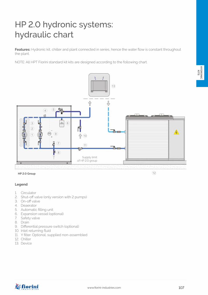
HP 2.0 hydronic systems:hydraulic chart
HP 2.0 Group
Supply limitof HP 2.0 group
Legend
1. Circulator2. Shut-off valve (only version with 2 pumps)3. On-off valve4. Deaerator5. Automatic filling unit6. Expansion vessel (optional)7. Safety valve8. Drain9. Differential pressure switch (optional)10. Inlet returning fluid11. Y filter. Optional, supplied non-assembled12. Chiller13. Device
Features: Hydronic kit, chiller and plant connected in series, hence the water flow is constant throughout the plant.
NOTE: All HPT Fiorini standard kit kits are designed according to the following chart.

108 www.fiorini-industries.com
6
12
7
3
11
5
9
1
13
10
2
4
14
8
HP 2.0 hydronic system:components
Components
1 Switchboard
2 Circulation pump (version with double pump, optional)
3 Removable bolted panel
4 Hinged panel
5 Shut-off valve
6 Water outlet
7 Water inlet
8 Pressure transmitter (only version with inverter)
9 Check valve (only version with double pump)
10 Ventilation grid
11 Safety valve
12 Automatic filling unit
13 Base
14 Automatic pressure relief

109www.fiorini-industries.com
Lt
WtLt
Wt
Ht
HtG2
G2
P2
P2
HY
DR
ON
IC
KIT
S
HP 2.0 hydronic system:dimensions
1 pumpDimensions
2 pumps (1 redundant)Dimensions
Pump modelLt
mmWtmm
Htmm
Ltmm
Wtmm
Htmm
G2inch
P2inch
PT2-PT3 790 650 1360 790 650 1360 1"1/2 1"1/2
P1-P2-P3-P4-P5 790 650 1360 790 650 1360 2"1/2 2"1/2
P6-P7-P8-P9 1200 790 1360 1200 790 1360 3" 3"
P10-P11-P12-P13-P14-P15-P16-P17-P18 1200 790 1360 1280 790 1600 4" 4"
P19-P20-P21 2000 1800 1575 2000 1800 1575 DN 200 UNI PN16 DN 200 UNI PN16
Layout of pump models from P19 to P21
Layout of pump models PT2, PT3, from P1 to P18
G2 To plantVictaulic connection
P2 From energy sourceVictaulic connection
Couplings legend

110 www.fiorini-industries.com
0
5
10
15
20
25
0 5 10 15 20 25 30
Flow rate (m3/h)
H (m
)
P2
P1
ΔP
HP 2.0 Hydronic systemsPrevalence and pressure loss curve
ΔP: Pressure drop HP unit
flow (m3/h)
flow (m3/h)

111www.fiorini-industries.com
0
5
10
15
20
25
30
0 5 10 15 20 25 30 35 40 45 50
Flow rate (m3/h)
H (m
)
P4 P3
P5
ΔP
0,0
5,0
10,0
15,0
20,0
25,0
30,0
35,0
40,0
45,0
0,0 10,0 20,0 30,0 40,0 50,0 60,0 70,0 80,0 90,0
Flow rate (m3/h)
H (m
)
P7
P6
P8
P9
ΔP
HY
DR
ON
IC
KIT
S
ΔP: Pressure drop HP unit
HP 2.0 Hydronic systemsPrevalence and pressure loss curve
flow (m3/h)
flow (m3/h)

112 www.fiorini-industries.com
0,0
5,0
10,0
15,0
20,0
25,0
30,0
35,0
40,0
45,0
50,0
0,0 20,0 40,0 60,0 80,0 100,0 120,0 140,0 160,0
H (m
)
P11
P10
P12P13
P14
ΔP
0,0
5,0
10,0
15,0
20,0
25,0
30,0
35,0
40,0
45,0
50,0
0,0 50,0 100,0 150,0 200,0 250,0
Flow rate (m3/h)
H (m
)
P16
P15
P17
P18
ΔP
0,0
10,0
20,0
30,0
40,0
50,0
60,0
0,0 50,0 100,0 150,0 200,0 250,0 300,0 350,0
Flow rate (m3/h)
H (m
)
P20
P19
P21
ΔP
flow (m3/h)
flow (m3/h)
ΔP: Pressure drop HP unit
HP 2.0 Hydronic systemsPrevalence and pressure loss curve
flow (m3/h)

113www.fiorini-industries.com
HY
DR
ON
IC
KIT
S
HP 2.0 hydronic systems:technical information
1 pump 2 pumps (1 redundant)
Pump model
F.L.IkW
F.L.A.(400/3/50)
A Code PriceWeight
kg Code PriceWeight
kg
PT2* 0,72 1,3 838060261X 100 838060262X 114
PT3* 0,72 1,3 838060263X 100 838060264X 114
P1 1,1 2,5 838060129X 129 838060119X 150
P2 1,5 3,2 838060130X 130 838060120X 151
P3 1,5 3,4 838060131X 131 838060121X 153
P4 2,2 4,8 838060132X 135 838060122X 157
P5 3 5,6 838060133X 137 838060123X 163
P6 3 6,1 838060107X 183 838060193X 256
P7 4 8,7 838060108X 190 838060194X 272
P8 5,5 10,4 838060109X 208 838060195X 311
P9 7,5 13,6 838060110X 224 838060196X 343
P10 5,5 10,4 838060111X 215 838060197X 323
P11 7,5 13,6 838060112X 231 838060198X 355
P12 9,2 17,2 838060235X 284 838060236X 407
P13 11 21,3 838060183X 284 838060217X 412
P14 15 27,7 838060184X 309 838060218X 503
P15 11 20,2 838060227X 279 838060228X 460
P16 15 26,6 838060185X 316 838060219X 549
P17 18,5 33 838060186X 319 838060220X 569
P18 22 40,4 838060187X 340 838060221X 587
P19 18,5 33 838060229X 703 838060230X 1265
P20 30 53,5 838060231X 844 838060232X 1519
P21 37 65,6 838060233X 865 838060234X 1557
Legend
F.L.I. Max absorbed powerF.L.A. Max absorbed currentPve Preload of expansion vesselPs Max operating pressureTmin Min temperature of the liquid
Pve (bar) 1,5 Ps (bar) 3 T min (°C) -10* PT2 and PT3 available in single-phase version on request

114 www.fiorini-industries.com
HP 2.0 hydronic systems: Capacityof the circuit and the expansion vesselMax water content in the device and dimensions of the expansion vessel
On chart 1 the max water volume in the hydraulic installation is indicated, compatible with the capacity of the expansion vessel and applicable to al HP 2.0 models. The safety valve also has a start-up value (3 bar for all models). If the effective water content in the device, as well as in the storage tank, exceeds the operating conditions in the chart, another/second expansion vessel should be installed to take the added water volume.
Tav. 1
Note: the expansion vessel is optional and should be ordered separately.
Operative conditions(1) cooling Min temp of fluid = 4°C Max temp of fluid = 40°C(2) heating (heat pump) Min temp of fluid = 4°C Max temp of fluid = 50°C
Tav. 2
Pump model Hydraulic height m 15 10
Preload of the expansion vessel bar 1,80 1,50
PT2 PT3 P1 P2 P3P4 P5
Circuit’s max water content (1) l 492 615
Circuit’s max water content (2) l 315 394
P6 - P18 Circuit’s max water content (1) l 984 1230
Circuit’s max water content (2) l 630 788
P19 - P21 Circuit’s max water content (1) l 1968 2460
Circuit’s max water content (2) l 1260 1576
Water/ glycol mix.
Water temperature
Correction factors Reference valuemax
°Cmin°C
10% 40 -2 0.507 (1)
10% 5 -2 0.686 (2)
20% 40 -4 0.434 (1)
20% 50 -4 0.604 (2)
30% 40 -6 0.393 (1)
30% 50 -6 0.555 (2)

115www.fiorini-industries.com
H max = 27 m (**)
Hl = 12,25 m H
P ba
r – 1
,5 b
arP
bar –
H/1
0,2
+ 0,
3
H = 0 m
H min (*)
HP
HY
DR
ON
IC
KIT
S
Hydronic systemsHP 2.0 preload of the expansion vessel
The expansion vessel, of all models, is preloaded with a standard value of 1.5 bar.The value has to be adapted though to the height H of the device.
The formula used to calculate the preload value of the expansion vessel is:P = (H /10.2)+0.3
LegendH: height of the device in metersP: preload of the expansion vessel in barShould the preload value be less than the standard val-ue, no intervention has to be carried out. This means that an installation with a height of less than 12.25 meters has a preload of 1.5 bar. In this case the operator should only check the pressure value and not intervene.
ExampleWe take a height H of 15.3. The preload value is:P = (15,3/10,2)+0,3= 1,8 bar
H: height of the deviceHmax: max height of the deviceH1: height when the preload of the expansion vessel is the same as the standard value* verify that the lowest point of the device can support the pressure** verify that the highest point of the device does not exceed the max height H max=27 m.
HP 2.0 hydronic systemuser’s conditionsNormal user conditions
The HP 2.0 hydronic group is designed to fit into air conditioning systems, normally coupled with a chiller or a heat pump.The groups are designed to work with water or eth-ylene glycol and water mixtures up to a maximum of 30%. For operation with percentages of higher glycols or with different fluids, you must consult our technical service.
The minimum operating temperature of the fluid is -10°C, of course with a mixture of water and glycol, while the maximum is 60°C. Special executions for operation with lower or higher temperature fluids are available on request.
The outdoor air temperature range is -20°C + 40°C. Again, special versions are available for operation outside the standard range.
The maximum working pressure of the group is 3 bars. Versions with maximum operating pressure are available on request. Also versions for open vessel operation (atmospheric pressure) can be made on request.

116 www.fiorini-industries.com
1
2
3
4
5
6
Expansion vessel kit
Manometer kit
Original conncetionVictaulic
Transformed connectionUNI-EN PN 16 Code Price
1"1/2 DN40 838081247X
DN50 838081248X
2" DN50 838081249X
DN65 838081250X
2"1/2 DN65 838081251X
DN80 838081252X
3" DN80 838081253X
DN100 838081254X
4" DN100 838081255X
DN125 838081256X
* WARNING: If the system operates 24 hours a day, 7 days a week, the pump alternation is not guaranteed by the standard group. In this case, we recommend the use of this accessory.
Programmable timer for alternating pumpsIn the dual pump configuration, the timer can be used to handle alternating pump operation at specified time intervals. Without the timer, the alternating pump operation occurs at each startup of the group. Default alternation every 48 hours programmable.
Differential pressure switchSecurity device that allows you to verify that there is flow inside the system. The device generates an alarm signal but does not automatically stop the machine.
Code Description Price
838081104X TIMER OPTION 48H
Code Description Price
838081583X MANOMETER KIT
Code Description Price
838081000X DIFFERENTIAL PRESSURE SWITCH
Code Description Price
838080861X ANTI-VIBRATING FOR HP PT2/PT3 AND FOR P1 A P18
838081286X ANTI-VIBRATING FOR HP P19/P20/P21
Code Description Compatible with Price
838081187X EXPANSION VESSEL 12L INNER HP 2.0 UP TO P18
838081195X EXPANSION VESSEL 25L INNER HP 2.0 UP TO P18
838081480X EXPANSION VESSEL 2x25L INNER HP 2.0 UP TO P18
838081616X EXPANSION VESSEL 3x25L INNER HP 2.0 UP TO P18
838081234X EXPANSION VESSEL 2x25L INNER HP 2.0 FOR P19/P20/P21 VERSIONS
Anti-vibrating feetSet of anti-vibrating feet to be placed on the machine's support points. The feet are supplied disassembled.
Galvanized Transformation in Victaulic connectionsThey transform the victaulic connections into UNI-EN PN 16 flanged connections. A version with the same diameter and one with a larger diameter is available. The codes and prices below are for single piece.
Hydronic systemsHP 2.0: accessories

117www.fiorini-industries.com
1
2
4
5
5
11
10
3
6
7
8
8
9
9
10
11
7
HY
DR
ON
IC
KIT
S
Inverter (special version) Each pump can be operated by an inverter. The units equipped with inverters have a pressure sensor, 0-10 bar, which communicates with the inverter with 4-20 mA signal. All adjustment parameters are pre-load-ed during the test run at the company. The user must choose only the desired set point pressure value.see page: 133
Antifreeze electric resistance kit (special ver-sion) The kit provides protection against freez-ing by means of a heating cable wound around piping. The kit also includes a bi-thermostatic antifreeze adjustment (-35 / + 35 ° C) and is supplied assembled, wired and tested.see page: 133
Soundproof coating (special version)The soundproofing is available, which attenuates the sound level of the machine significantly.see page: 133
Filter (special version)Mesh filter, with 1000 micron holes, can be placed outside the unit to protect the pumps from any impurities in the equipment.see page: 133
Balancing valves (special version)Valve can be connected externally to balance the flow within the circuit. see page: 133
Wooden box packing (special version)Extra protective packing suitable for risky and long-distance transport.see page: 133

118 www.fiorini-industries.com
Hydronic systemsVKB 2.0
The VKB 2.0 units are buffer storage tanks with ac-cessories (without circulation pump) designed in order to significantly reduce the set-up time for the conditioning and cooling devices.
With all hydraulic components which are indispensa-ble for the correct functioning of the hydraulic circuit for the distribution of chilled water. The components can be coupled with all kind of water coolers. The units consist of an insulated buffer tank, an expansion vessel, a safety valve, a deaerator, a fill/drain valve and a manometer.
The VKB 2.0 units are enveloped in a supporting structure in a galvanized steel and powder coated panels and base. They are designed to guarantee an easy inspection and maintenance of the compo-nents. The tank, which is hydraulically inserted be-tween the cooling station and the fan-coils, makes the water content in the entire installation increase, by increasing the pause between the shutdown of the compressor and the next start-up. In this way, the number of start-ups is significantly reduced, which improves the life span and performance of the com-pressor. The broad range of storage tanks makes it possible to meet every requirement. Every unit is as-sembled in our factory and tested to guarantee our trustworthiness.
Available versions
VKB 2.0 is available in the following sizes: 250, 500, 1000 and 1500 litres.
Accessories
See pag. 116 for the list of available accessories
Tank insulated with anti-condensate elastomer

119www.fiorini-industries.com
HY
DR
ON
IC
KIT
S
Hydronic systemsVKB 2.0 Layout 1 STANDARD
Hydronic systemsVKB 2.0 Layout 2 SPECIAL VERSION
Legend
1. Buffer unit, vkb 2.0 Series2. Cooling unit/heat pump3. Primary pump unit4. Primary pump unit (redundant)5. Filling unit
Legend
1. Buffer unit, vkb 2.0 Series2. Cooling unit/heat pump3. Primary pump unit4. Primary pump unit (redundant)
Hydronic kit, chiller and plant con-nected in series, so constant water flow throughout the plant.
Hydronic Kit and Chiller create the primary circuit, Hydronic Kit and Plant create the secondary circuit. Hence, the two circuits have inde-pendent flow rates. The VKB shown below is a special execution with baffles.
(special execution with baffles)

120 www.fiorini-industries.com
4
1
3
5
6
8
9
7
2
Hydronic systemsVKB 2.0
VKB 2.0 Description of the main components
• Storage tank The storage tank is made of varnished carbon steel plates and is insulated with closed cell elastomer . This type of insulation, guarantees an excellent resistance to condensate formation.
• Fill up valve This valve refills the hydraulic circuit in the demand peak phase as well as during normal functioning.
• Safety valve Calibrated at 3 bar and with canalised drain. It protects the unit from possible overpressure.
• Automatic valve for air drain Placed on the upper part of the unit, it drains air from the unit.
• Drain valve It drains air from the lowest point of the tank to make drainage possible.
• Supporting structure The base is made of thick steel plates varnished. Thebasement and panels are made in galvanized steel and powder coated which are resistant to atmospheric agents. All this makes it possible for the VKB 2.0 to be installed in non-technical spaces and in places exposed to atmospheric agents.
• Expansion vessel Supplied with a membrane, preloaded nitrogen and with dimensions that can absorb varying volumes of liquid derived from the various temperatures.
• Manometer This device is placed on the tank and indicates the internal pressure.
Components
1 Storage tank
2 Fill-up valve
3 Automatic safety valve
4 Drain
5 Supporting structure
6 Expansion vessel
7 Manometer
8 Predisposition for electrical resistance
9 Predisposition for thermostat

121www.fiorini-industries.com
Lt
Wt
P1
G1
Ht
HY
DR
ON
IC
KIT
S
Hydronic systemsVKB 2.0
Capacityl
Vessell
Vessel calibration bar
Safety valvebar
Couplingsinch
Wtmm
Ltmm
Htmm
P1mm
G1mm
250 12 1 3 2” 590 750 1600 420 1220
500 18 1,5 3 3” 750 1000 1850 420 1470
1000 25 1,5 3 4” 1100 1100 1850 610 1410
1500 2x25 1,5 3 4" 1200 1200 1950 650 1450
Capacityl Code Price
Dimensions with packaging
mmWeight
kg
250 838050090X 625x785x1670 95
500 838050091X 800x1050x1920 155
1000 838050092X 1150x1150x1920 255
1500 838050016 1250X1250X2020 313
G1 From plantThreaded connection
P1 To energy sourceThreaded connection
Couplings legend

122 www.fiorini-industries.com
VKB 2.0 hydronic systems: Capacityof the circuit and the expansion vessel
Max water content in the device and dimensions of the expansion vessel
On chart 1 the max water volume in the hydraulic installation is indicated, compatible with the capacity ofthe expansion vessel and applicable to all VKB 2.0 models. The safety valve also has a start-up value (3 bar forall models). If the effective water content in the device, as well as in the storage tank, exceeds the operatingconditions in the chart, another/second expansion vessel should be installed to take the added water volume.
Tav. 1
Note: the expansion vessel is optional and should be ordered separately.
Condizioni operative:(1) cooling Min temp of fluid = 4°C Max temp of fluid = 40°C(2) heating (heat pump) Min temp of fluid = 4°C Max temp of fluid = 50°C
Tav. 2
Model Hydraulic height H m 15 10
Expansion vessel preload bar 1,8 1,5
VKB 2,0 250 lCircuit’s max water content (1) l 492 615
Circuit’s max water content (2) l 315 394
VKB 2,0 500 lCircuit’s max water content (1) l 708 885
Circuit’s max water content (2) l 453 567
VKB 2,0 1000 lCircuit’s max water content (1) l 984 1230
Circuit’s max water content (2) l 630 788
VKB 2,0 1500 lCircuit’s max water content (1) l 1968 2460
Circuit’s max water content (2) l 1260 1576
Water/ glycol mix.
Water temperature
Correction factors Reference valuemax
°Cmin°C
10% 40 -2 0.507 (1)
10% 5 -2 0.686 (2)
20% 40 -4 0.434 (1)
20% 50 -4 0.604 (2)
30% 40 -6 0.393 (1)
30% 50 -6 0.555 (2)

123www.fiorini-industries.com
H
P ba
r - 1
,5 b
arP
bar -
H/1
0,2
+ 0,
3
H min (*)
HI = 12,25 m
H max = 27 m (**)
H = 0 m
HY
DR
ON
IC
KIT
S
Hydronic systemsVKB 2.0 preload of the expansion vessel
The expansion vessel, of all models, is preloaded with a standard value of 1.5 bar.The value has to be adapted though to the height H of the device.The formula used to calculate the preload value of the expansion vessel is:P = (H /10.2)+0.3
LegendH: height of the device in metersP: preload of the expansion vessel in barShould the preload value be less than the stand-ard value, no intervention has to be carried out. This meansthat an installation with a height of less than 12.25 meters has a preload of 1.5 bar. In this case the op-eratorshould only check the pressure value and not inter-vene.
ExampleWe take a height H of 15.3. The preload value is:P = (15,3/10,2)+0,3= 1,8 bar
H: height of the deviceHmax: max height of the deviceH1: height when the preload of the expansion vessel is the same as the standard value* verify that the lowest point of the device can support the pressure** verify that the highest point of the device does not exceed the max height H max=27 m.
Normal user's conditionsThe VKB 2.0 hydronic group is designed to be incor-porated into conditioning systems, normally coupled with a chiller or a heat pump.The units are designed to work with water or ethylene glycol and water mixtures up to a maximum of 50%. For operation with percentages of higher glycols or with different fluids, you must consult our technical service.
The minimum operating temperature of the fluid is -10 ° C, of course with a mixture of water and glycol, while the maximum is 60 ° C. Special executions for operation with lower or higher temperature fluids are available on request.
The outdoor air temperature range is -20 ° C + 40 ° C. Again, special versions are available for operation outside the standard range.
The maximum working pressure of the group is 3 bars. Versions with maximum operating pressure are available on request. Also versions for open vessel operation (atmospheric pressure) can be made on request.

124 www.fiorini-industries.com
1
2
3
4
Hydronic systemsVKB 2.0 accessories
From threaded to flanged galvanized connectionsThe codes and prices below are for single piece.
Electrical resistorIP 65 Protection
Temperature controls
From threaded to Victaulic galvanized connectionsThe codes and prices below are for single piece.
Originalconnection
Transformed connection
uni-en pn 16 Code Price
1”1/2DN 40 838081200X
DN 50 838081201X
2”DN 50 838081202X
DN 65 838081203X
2”1/2DN 65 838081204X
DN 80 838081205X
3”DN 80 838081206X
DN 100 838081207X
4”DN 100 838081208X
DN 125 838081209X
Originalconnection
Transformed connection Code Price
1”1/2 1"1/2 838081211X
2" 838081212X
2” 2" 838081213X
2"1/2 838081214X
2”1/2 2"1/2 838081215X
3" 838081216X
3” 3" 838081217X
4" 838081218X
4” 4" 838081219X
5" 838081220X
DescriptionTemperature
range Safety range Code Price
Thermostat 0 ÷ 90 °C - 822010004
Bithermostat 0 ÷ 90 °C fix 100 °C 822010006
AntifreezeBithermostat
-30 ÷ 30 °C 0 ÷ 90 °C 822010007
PowerW
VoltageV
Element number
Connectiondiameter
inchLength
mm Code Price
1300 230/380 3 2” 220 824100008
2000 230/380 3 2” 290 824100009
3000 230/380 3 2” 340 824100010
4000 230/380 3 2” 390 824100012
125www.fiorini-industries.com
1 4
5
6
3
2
5
6
HY
DR
ON
IC
KIT
S
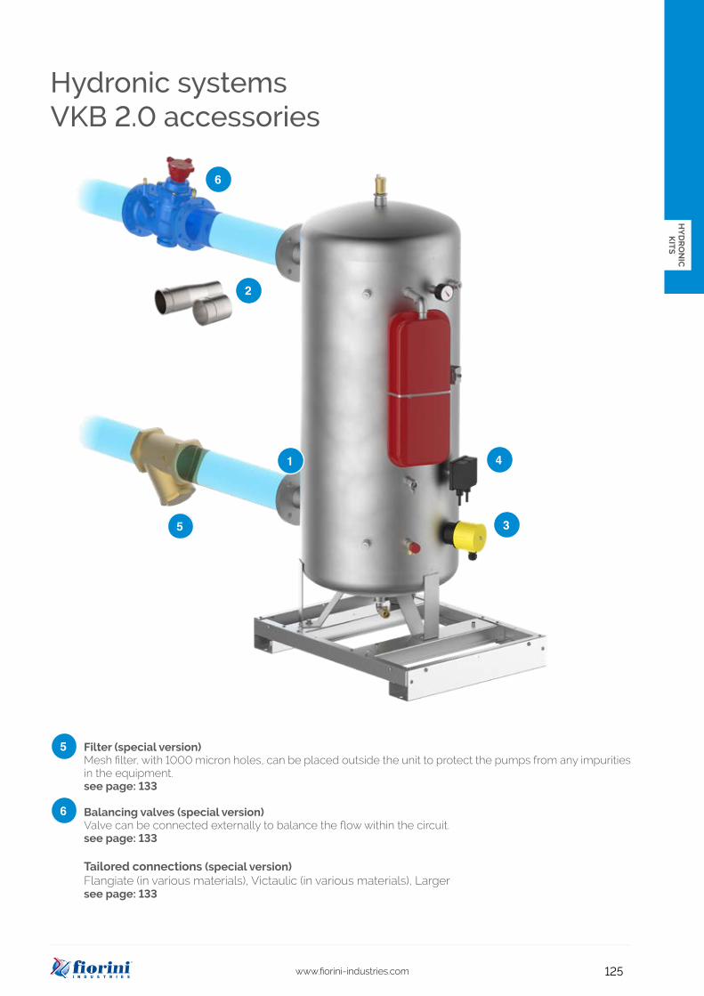
Hydronic systemsVKB 2.0 accessories
Filter (special version)Mesh filter, with 1000 micron holes, can be placed outside the unit to protect the pumps from any impurities in the equipment.see page: 133
Balancing valves (special version)Valve can be connected externally to balance the flow within the circuit. see page: 133
Tailored connections (special version)Flangiate (in various materials), Victaulic (in various materials), Largersee page: 133