svs-760f fishfinder operations manual - si-tex · fishfinder offer’s superior fish detection and...
TRANSCRIPT
- 1 -
SVS-760F FISHFINDER
OPERATIONS MANUAL

- 2 -
WARNING Always follow this safety instruction to prevent death or injury.
CAUTION
Follow this safety instruction to avoid possible injury or damage to your property.
Symbol “△” is a CAUTION or WARNING label indicating the
safety instruction.
WARNING This symbol is an Electrical Shock WARNING label.
Symbol is an instruction that you must not violate. (This symbol instructs NOT to disassemble the system components)
Symbol is an operation instruction that you must follow. (This symbol shows the main power OFF instruction.)
- 3 -
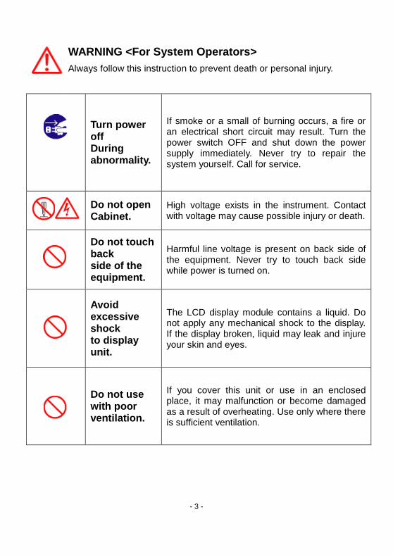
WARNING <For System Operators>
Always follow this instruction to prevent death or personal injury.
Turn power off During abnormality.
If smoke or a small of burning occurs, a fire or an electrical short circuit may result. Turn the power switch OFF and shut down the power supply immediately. Never try to repair the system yourself. Call for service.
Do not open Cabinet.
High voltage exists in the instrument. Contact with voltage may cause possible injury or death.
Do not touch back side of the equipment.
Harmful line voltage is present on back side of the equipment. Never try to touch back side while power is turned on.
Avoid excessive shock to display unit.
The LCD display module contains a liquid. Do not apply any mechanical shock to the display. If the display broken, liquid may leak and injure your skin and eyes.
Do not use with poor ventilation.
If you cover this unit or use in an enclosed place, it may malfunction or become damaged as a result of overheating. Use only where there is sufficient ventilation.
- 4 -
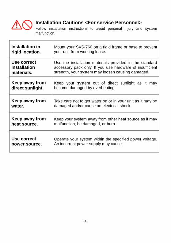
Installation Cautions <For service Personnel> Follow installation instructions to avoid personal injury and system malfunction.
Installation in rigid location.
Mount your SVS-760 on a rigid frame or base to prevent your unit from working loose.
Use correct Installation materials.
Use the installation materials provided in the standard accessory pack only. If you use hardware of insufficient strength, your system may loosen causing damaged.
Keep away from direct sunlight.
Keep your system out of direct sunlight as it may become damaged by overheating.
Keep away from water.
Take care not to get water on or in your unit as it may be damaged and/or cause an electrical shock.
Keep away from heat source.
Keep your system away from other heat source as it may malfunction, be damaged, or burn.
Use correct power source.
Operate your system within the specified power voltage. An incorrect power supply may cause

- 5 -
Maintenance Cautions<For Maintenance Personnel>
Use the following safety precaution internal inspection.
Discharge capacitors.
High voltage may be retained in the capacitors if the high-tension circuit several minutes after you have turned the power switch off.
Check that power is OFF
To prevent an electrical injury due to erroneous power switching, make sure that the main power supply and the system power switch are both in the off position. Additionally, attach a safety label showing that service is in progress.
Avoid EMI. Take care not to damage the ESDs (Electrostatic Sensitive Devices) by static electricity from carpet and cloths.
Avoid dust. Wear a safety mask so as not to breath in dust during inspection or cleaning inside your system instruments.
- 6 -
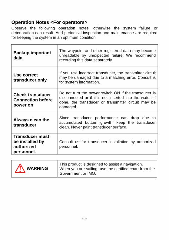
Operation Notes <For operators> Observe the following operation notes, otherwise the system failure or deterioration can result. And periodical inspection and maintenance are required for keeping the system in an optimum condition.
Backup important data.
The waypoint and other registered data may become unreadable by unexpected failure. We recommend recording this data separately.
Use correct transducer only.
If you use incorrect transducer, the transmitter circuit may be damaged due to a matching error. Consult is for system information.
Check transducer Connection before power on
Do not turn the power switch ON if the transducer is disconnected or if it is not inserted into the water. If done, the transducer or transmitter circuit may be damaged.
Always clean the transducer
Since transducer performance can drop due to accumulated bottom growth, keep the transducer clean. Never paint transducer surface.
Transducer must be installed by authorized personnel.
Consult us for transducer installation by authorized personnel.
WARNING
This product is designed to assist a navigation. When you are sailing, use the certified chart from the Government or IMO.
- 7 -
SVS-760 Fishfinder System
CAUTION The SVS-760 Color LCD Fishfider Systems employs the latest in proven technology to provide
accurate fish & bottom information. The Plotter functions of SVS-760 are totally dependent upon the
capability of the navigation source to provide accurate position information. This device is only an aid
to navigation. It should be used in conjunction with all other navigation accuracy. For safety, always
resolve any uncertainty before continuing navigation.
There is no direct relationship between the color of water areas and their depth. The navigator shall
always query the area for depth information and use the official paper chart.
CAUTION The performance of LCD displays are degraded by continuous direct exposure to ultraviolet rays.
Locate your SVS-760 Display away from direct sunlight. When not in use. Keep the display covered.
DISPLAY BREAKAGE WARNING The LCD display module contains a liquid. If the display is broken and the liquid contacts your skin,
wash it off immediately in running water for 15 minutes. If the liquid contacts your eyes, immediately
flush your eyes with running water for 15 minutes. Contact a physician if any abnormal symptom is
experienced.
- 8 -
Welcome
Thank you for purchasing the SVS-760 from Si-Tex.
The SVS-760 is a premium multifunction Fish Finder System. SVS-760 front panel keyboard and its
wide screen viewing area make placement easy. Although SVS-760 offers many advanced features,
operation is simplified through the use of popup menus similar to those found on personal computers.
The SI-TEX SVS-760 Color LCD Fishfider System opens a new chapter of performance and
integration in Fishfinder system display and management. Whether you are a Cruiser or Sport
fisherman or both, SVS-760 gives you the information you need.
Features of the SVS-760
Comprised of a display unit and a dual frequency transducer.
The main features of the SVS-760 are
▶ A large 7” Direct Sunlight Viewable High Definition LCD Display, in a vertical format to provide
maximum sonar resolution! 480 x 800 pixels.
▶ Fishfinder offer’s Superior fish detection and bottom discrimination using the new SI-TEX All Digital
Sounder System.
▶ Instantly adapts to changing seabed and water conditions providing fully automatic “hands free”
operation.
▶ A Powerful best in class 600 watt dual frequency 50/200Khz transceiver.
▶ Digital technology eliminates unwanted noise and provides the clearest images possible at all
times.
▶ Multiple Display Modes: Normal (Single or Dual Freq.), Bottom Zoom, Bottom Lock, Shift, Split
Screens, GPS Position, Waypoint Steering, Navigation Highway.
▶ Auto & Manual Range & Gain Controls, Each Frequency can be independently controlled! Also,
Auto & Manual Shift.
- 9 -
Features of the SVS-760
▶ 10 Page Screen Capture Memory allows you to take Snap Shots of the Fish Finder Screen and
save them to memory.
▶ 10 Event point memory allows you to instantly save a Fishing location and compute your course
steering info back to the spot.
▶ Waterproof to IPX6 International Standard
▶ Very easy to operate, with front panel knobs for Gain and STC, Simple Menu Format, and all
controls labeled in plain English.
▶ New White Line / Black Line Bottom Discriminator .
▶ Fish Symbols
▶ Depth Alarm, Sea Temperature Alarm, Fish Alarm
▶ Standard equipment includes Snap on Sun Cover.
- 10 -
Fishfinder System
Introduction
The SVS-760 is a premium multifunction command and control center. SVS-760 front panel keyboard
and its wide screen with wide viewing area make placement easy. Although SVS-760 offers many
advanced features, operation is simplified through the use of popup menus similar to those found on
personal computers.
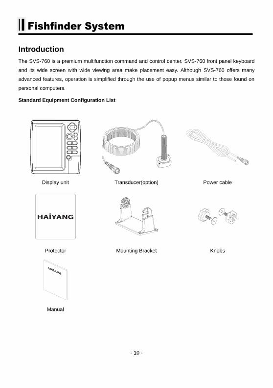
Standard Equipment Configuration List
Display unit Transducer(option) Power cable
Protector Mounting Bracket Knobs
Manual
- 11 -
Fishfinder system
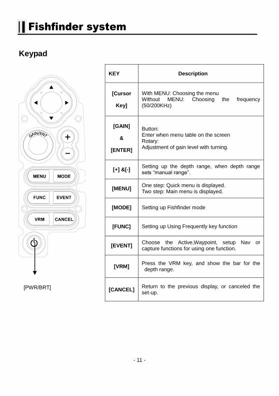
Keypad
KEY Description
[Cursor
Key]
With MENU: Choosing the menu Without MENU: Choosing the frequency (50/200KHz)
[GAIN]
&
[ENTER]
Button: Enter when menu table on the screen Rotary: Adjustment of gain level with turning.
[+] &[-] Setting up the depth range, when depth range sets “manual range”.
[MENU] One step: Quick menu is displayed. Two step: Main menu is displayed.
[MODE] Setting up Fishfinder mode
[FUNC] Setting up Using Frequently key function
[EVENT] Choose the Active,Waypoint, setup Nav or capture functions for using one function.
[VRM] Press the VRM key, and show the bar for the depth range.
[CANCEL] Return to the previous display, or canceled the set-up.
[PWR/BRT]
- 12 -
Fishfinder system
How to use [Power/Brightness]
▶ Press [PWR/BRT]
1.Use PWR:
To turn off the power, keep pressing the [BRT/PWR] until the end of counting.
2.Use BRT:
Press [BRT/PWR] shortly and the brightness can be controlled. Use the arrow keys [←][→]of the
cursor to control the brightness and the contrast.
3. Use day/night mode
Press [BRT/PWR] shortly and change mode. Use the arrow keys [↓][↑] of the cursor to change mode.
Choosing the frequency on the dual
▶ Press [↑][↓]
You can see the red color is moving with the up and the down. In the active frequency in the red, it’s
on operation.
Choose the Gain & STC
▶ Press [←][→]
You can see the red color is moving with the right and the left. In the active Gain & STC in the red, it’s
on operation.
Auto / Manual Gain
▶ Press [ENTER]
Press the key changes Auto Gain / Manual Gain.
(* Setting is available individually)
Set Gain
▶ Tune [GAIN]
Turn to the left, the gain level will be decreasing. Turn to the right, the gain level will be increasing.
(It is applied Auto Gain Adjustment, when the mode sets “Auto gain mode”)
- 13 -
Fishfinder system
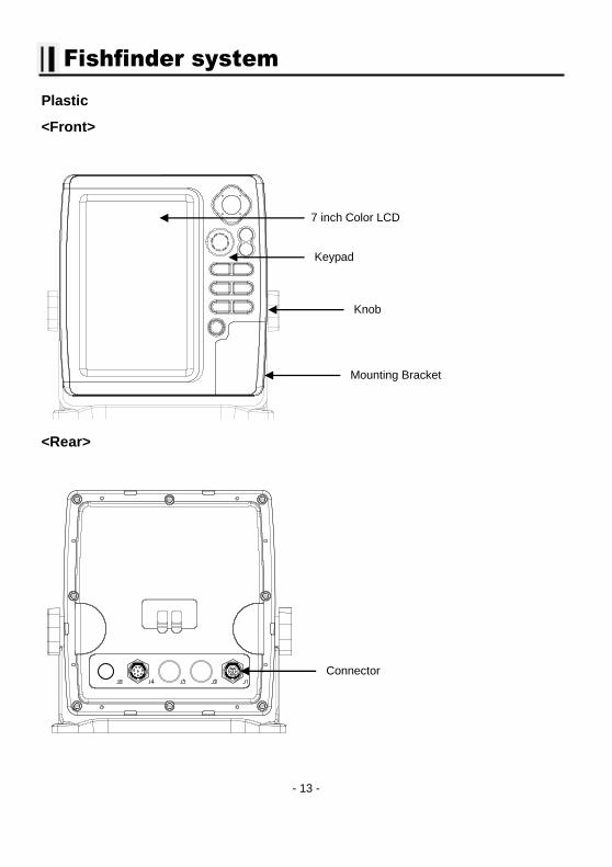
Plastic
<Front>
<Rear>
7 inch Color LCD
Keypad
Knob
Mounting Bracket
Connector
- 14 -
Fishfinder system
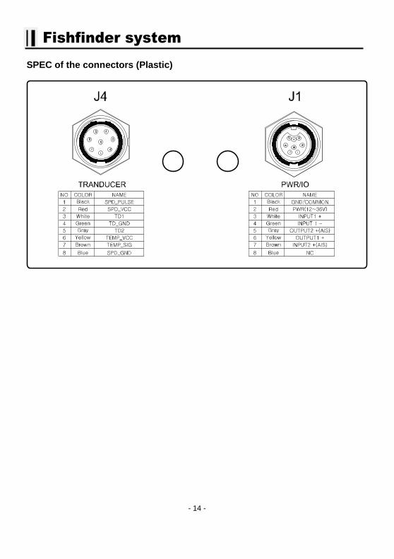
SPEC of the connectors (Plastic)

- 15 -
- 16 -
SVS-760 Introduction
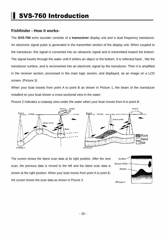
Fishfinder - How it works-
The SVS-760 echo sounder consists of a transceiver display unit and a dual frequency transducer.
An electronic signal pulse is generated in the transmitter section of the display unit. When coupled to
the transducer, this signal is converted into an ultrasonic signal and is transmitted toward the bottom.
The signal travels through the water until it strikes an object or the bottom. It is reflected back , hits the
transducer surface, and is reconverted into an electronic signal by the transducer. Then it is amplified
in the receiver section, processed in the main logic section, and displayed, as an image on a LCD
screen. (Picture 3)
When your boat travels from point A to point B as shown in Picture 1, the beam of the transducer
installed on your boat shown a cross-sectional view in the water.
Picture 2 indicates a cutaway view under the water when your boat moves from A to point B.
The screen shows the latest scan data at its right position. After the next
scan, the previous data is moved to the left and the latest scan data is
shown at the right position. When your boat moves from point A to point B,
the screen shows the scan data as shown in Picture 3.
- 17 -
Installation of the SVS-760
A careful installation will assure maximum performance from your new SVS-760.
Display Unit Location
Select a location for your Display unit that provides easy viewing from all likely operator’s positions. The display unit is designed to be mounted on either a console or from an overhead surface. The Display unit is also designed for flush mounting using six threaded holes on the rear panel. Locate the display in an area with protection from the elements and avoid direct sunlight on the viewing window. Also, consider access to the rear panel of the unit for connecting power and cables to the various remote sensors. The mounting surface must be flat and solid to support the unit and prevent vibration. There should be access to the inside of the surface to permit through bolt fastening for the mounting bracket.
Display Unit Installation
Temporarily install the mounting bracket on the SVS-760 display unit and place the unit at the selected location.
CAUTION
The Display unit is unstable when the mounting bracket is not secured. Hold the unit in place
at all times.
Check the suitability of the location and make any adjustments. When all is satisfactory, use the holes in the mounting bracket as a guide and mark the holes locations on the mounting surface.
- 18 -
Installation
Drill a 1/4 in. diameter hole at each marked location. Mount the Display unit bracket using bolts
through the mounting surface. Place large flat washers on the opposite side of the mounting surface
from the bracket and then install lock washers and nuts. Tighten securely.
Install the display unit into the mounting bracket. Check alignment and operation of the pivots and
security of the mounting. Make any adjustments necessary to prevent binding and assure even
meshing of the pivot locking washers. It is advised to remove the display unit and store it in a safe
place to prevent damage during the rest of the installation process.
Power Connection
Power is supplied to the Fishfinder Unit through a connector on the rear panel of the display unit.
Route the power cable from the Fishfinder Unit location to the ship’s power distribution panel.
Connect the black wire to a battery negative (-) terminal of the power panel.
Connect the white wire to a fused battery positive (+) terminal of the power panel ( 12 to 24 Vdc
nominal). If a fused terminal is not available, install an in-line fuse holder.
Transducer Connection
There are many transducers available which may be used to expand the capabilities of the SVS-760
Fishfinder Unit. Connectors for these accessories are provided on the rear panel of the Fishfinder Unit.
See table on following page for list of optional transducers
- 19 -
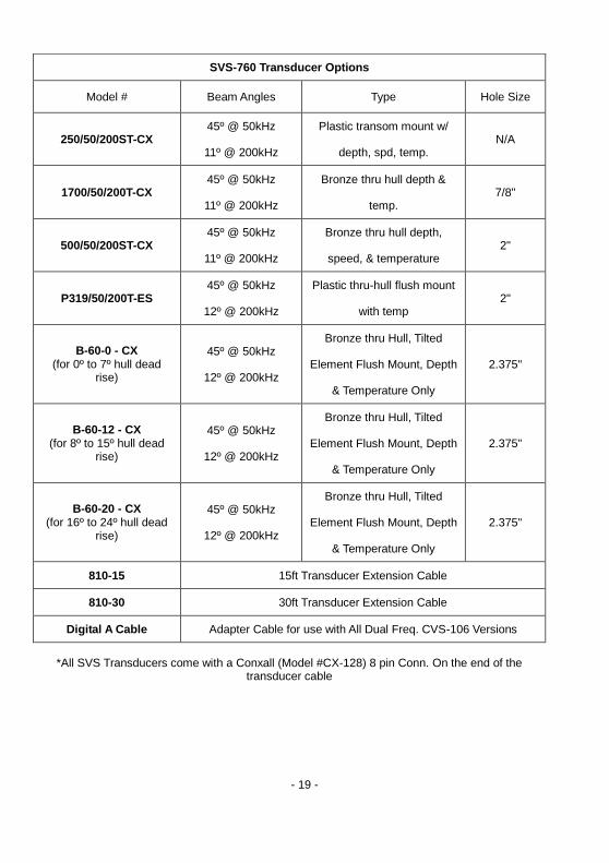
SVS-760 Transducer Options
Model # Beam Angles Type Hole Size
250/50/200ST-CX 45º @ 50kHz
11º @ 200kHz
Plastic transom mount w/
depth, spd, temp. N/A
1700/50/200T-CX 45º @ 50kHz
11º @ 200kHz
Bronze thru hull depth &
temp. 7/8"
500/50/200ST-CX 45º @ 50kHz
11º @ 200kHz
Bronze thru hull depth,
speed, & temperature 2"
P319/50/200T-ES 45º @ 50kHz
12º @ 200kHz
Plastic thru-hull flush mount
with temp 2"
B-60-0 - CX (for 0º to 7º hull dead
rise)
45º @ 50kHz
12º @ 200kHz
Bronze thru Hull, Tilted
Element Flush Mount, Depth
& Temperature Only
2.375"
B-60-12 - CX (for 8º to 15º hull dead
rise)
45º @ 50kHz
12º @ 200kHz
Bronze thru Hull, Tilted
Element Flush Mount, Depth
& Temperature Only
2.375"
B-60-20 - CX (for 16º to 24º hull dead
rise)
45º @ 50kHz
12º @ 200kHz
Bronze thru Hull, Tilted
Element Flush Mount, Depth
& Temperature Only
2.375"
810-15 15ft Transducer Extension Cable
810-30 30ft Transducer Extension Cable
Digital A Cable Adapter Cable for use with All Dual Freq. CVS-106 Versions
*All SVS Transducers come with a Conxall (Model #CX-128) 8 pin Conn. On the end of the
transducer cable
- 20 -
Installation
Installing the Transducer Cable-
Thru-Hull and transom-Mount Installation
cable, with the connector attached, is supplied with the transducer. During the installation, do not cut
the transducer cable or remove the connector. Do not try shorten or splice the cable. The
transducer cable includes several wires, along with shielding and insulation. If the cable is cut, it
cannot be repaired. (Cutting the cable will also void the warranty.) During installation, if you need to
drill any holes for the cable, they must be large enough to accept the connector .(3/4" or 19mm)
This will allow you to complete the installation without cutting the wire.
1st) For a transom-mount installation - Route the cable up and over the top edge of transom. Secure
the cable using cable clamps. (These clamps are available from your local marine equipment supplier.)
If you do not want to expose the cable on the deck, you may drill a new hole (3/4" or 19mm) through
the transom for the cable. (Remember - this hole must be large enough to accept the cable with the
connector attached. Do not cut the cable!) To seal the opening, use a feed-thru cap where the cable
passes through the transom.
2nd) For either type of installation - Run the cable through the interior of the boat.
3rd) Be careful not to tear the cable jacket when passing it through bulkheads and other parts of
your boat. Secure the cable in place using Nylon Wire Ties. Coil the extra cable and tie it out of the
way.
4th) If transducer cable is not long enough, 15 & 30 foot extension cables are available from SI-TEX
When you attach the extension cable, be sure that the connections are tight and watertight. Use Dow
Corning DC-4 or an equivalent sealing compound to protect the connector assemblies.
- 21 -
Installation
Installing the Power Cable-
1st) The 6-foot power cable supplied with the display unit should reach the source of DC power.
Connect the power leads directly to the main battery isolation switch or breaker, or route the power
leads to the DC power distribution panel. At the power source, connect the red wire to the positive
terminal (+), and the black wire to the negative terminal (-). The negative terminal may also be called
"ground" or "earth." (The display unit is internally protected if you accidentally reverse the polarity of
the power wires.)
2nd
) Attach the red or positive wire to a 5 amp circuit breaker. If the unit is connected directly to the
boat's battery, include a 2amp in-line fuse. (In-line fuses are available at most marine supply stores.)
3rd
) To prevent any interference or electrical noise, separate the Fishfinder power wiring as much as
possible from other devices. See the section on "EMC Installation Guidelines."
4th
) If you need to extend the power wiring by more than 10 feet, use a larger wire size. This will
allow the wires to deliver the correct voltage in spite of the longer wire distance. For runs of 20 to 35
feet, use #14 AWG wire. If you need to extend the power wiring, be sure all electrical connections
are solid and durable. Insulate all connections using heat-shrink tubing or electrical tape. You may use
crimp connectors or a terminal strip, but be sure to use good-quality marine-grade parts.
5th
) Plug in the power cable at the rear of the display unit.
6th
) When you press the Power button, the display unit should turn on. If the unit will not turn on and
you suspect that you may have reversed the power connections, check the DC power lines all the way
back to the battery. If the polarity is not correct, reconnect the leads properly and try again.
(The display unit is internally protected if you accidentally reverse the polarity of the power wires.)
- 22 -
Installation
Installing a Thru-Hull Transducer
Follow these instructions if you are installing the thru-hull transducer.
1st) Once you have decided where to install the transducer, drill the hole for the part. Begin by
drilling a small pilot hole (1/8" or 3mm) from the inside of the hull. (This small hole can be filled easily if
the mounting location is not suitable.) Before you drill the hole, be sure you will be able to reach the
large nut on the top of the transducer, once it has been mounted. Also be sure there will be enough
clearance for the cable. If there is a strake or other feature on the hull, drill from the outside of the hull
instead.
2nd
) Drill a larger hole from the outside of the hull using the appropriate size hole saw or paddle bit
for the selected transducer.
3rd
) Uncoil the transducer cable. Remove the large hex nut from the housing and slide it over the end
of the cable.
4th
) Thread the cable through the hole to the inside of the hull. Never pull or carry the transducer in
place by pulling on the transducer cable.
5th
) Apply a thin layer of sealant (1/8"" or 3mm) to the transducer between the upper flat surface of
the transducer and the faring block. Use a high quality marine sealant suitable for underwater use.
(Caution do not use 3M 5200) Also apply a thin layer up the side walls. this should cover all of the
threads where the part will touch the hull material, plus an additional 1/4""(6mm). This will seal the
threads for the large hex nut.
6th
) Push the transducer housing (with the sealant applied) into the hole from the outside of the hull.
Twist the housing slightly to squeeze out any excess sealant and to get a good seal. Be sure that the
transducer is aligned so that the correct part of the unit is toward the bow of the vessel. Hold or prop
the transducer in place temporarily.
- 23 -
Installation
Installing a Thru-Hull Transducer
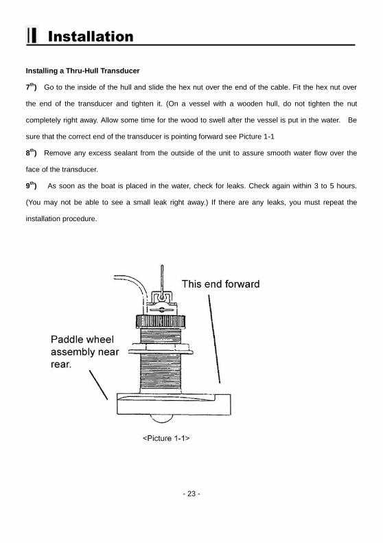
7th
) Go to the inside of the hull and slide the hex nut over the end of the cable. Fit the hex nut over
the end of the transducer and tighten it. (On a vessel with a wooden hull, do not tighten the nut
completely right away. Allow some time for the wood to swell after the vessel is put in the water. Be
sure that the correct end of the transducer is pointing forward see Picture 1-1
8th
) Remove any excess sealant from the outside of the unit to assure smooth water flow over the
face of the transducer.
9th
) As soon as the boat is placed in the water, check for leaks. Check again within 3 to 5 hours.
(You may not be able to see a small leak right away.) If there are any leaks, you must repeat the
installation procedure.
- 24 -
Installation
Positioning the Transom-Mount Transducer
Follow these instruction if you are installing the transom-mount transducer.
Begin by finding the best location for the mounting bracket. Here are the rules:
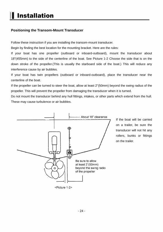
If your boat has one propeller (outboard or inboard-outboard), mount the transducer about
18"(455mm) to the side of the centerline of the boat. See Picture 1-2 Choose the side that is on the
down stroke of the propeller.(This is usually the starboard side of the boat.) This will reduce any
interference cause by air bubbles.
If your boat has twin propellers (outboard or inboard-outboard), place the transducer near the
centerline of the boat.
If the propeller can be turned to steer the boat, allow at least 2"(50mm) beyond the swing radius of the
propeller. This will prevent the propeller from damaging the transducer when it is turned.
Do not mount the transducer behind any hull fittings, intakes, or other parts which extend from the hull.
These may cause turbulence or air bubbles.
If the boat will be carried
on a trailer, be sure the
transducer will not hit any
rollers, bunks or fittings
on the trailer.
- 25 -
Installation
Mounting the Transom-Mount Transducer
Follow these instructions if you are installing the transom-mount transducer.
1st). On a boat with a fiberglass hull, the leading edge of the transducer should extend 1/8""(3.2mm) to
1/4""(6mm) below the bottom edge of the hull. See picture 1-3. On an aluminum hull, the transducer
should extend a bit more - 1/4"(6mm) to 3/8"(9mm). If the boat will be operated at high speeds, the
transducer may be mounted closer to the centerline of the hull.
2nd
) The lower surface of the transducer should tilt down toward the rear at a slight angle(2° to 5°). The
mounting bracket includes a wedge. Depending on the angle of the transom on your boat, you may
need this wedge to get the correct angle for the bottom of the transducer.
3rd
) Looking at the rear of the boat, be sure the bracket is vertical (perpendicular to the water line).
4th
) Hold the bracket (and the wedge, if used) against the transom and trace the position of the screw
slots.
5th
) Remove the bracket. The screws in the outer slots should be placed about 1/4"(6mm) up from
the bottom of each slot. The screw in the center slot should be placed 1/4" (6mm) down from the top.
(This will allow you to adjust the bracket up or down a bit.)
Drill pilot holes 3/4""(19mm) deep. Use a 9/64" (3.5mm) drill bit. To prevent drilling too deeply, wrap
masking tape around the drill bit about 7/8" (22mm) from the tip. Drill in only as far as the tape marker.
If you are attaching the bracket to a fiberglass hull, you can minimize any surface cracking of the gel
coat. Before drilling each pilot hole, drill a shallow hole (chamfer) at each location about 1/16" (1.5mm)
deep. Use a 1/4"(6mm) drill bit.
6th
) Attach the bracket to the hull using the pinhead screw with flat washers. Before you tighten the
screws, apply a good-quality marine sealant to the pilot hole. This will protect the hull from water
penetration. Do not tighten the screws completely yet.
- 26 -
Installation
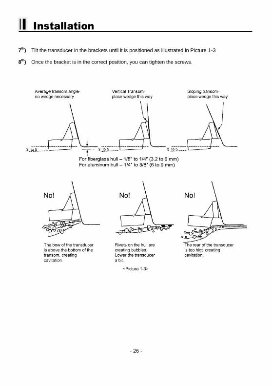
7th
) Tilt the transducer in the brackets until it is positioned as illustrated in Picture 1-3
8th
) Once the bracket is in the correct position, you can tighten the screws.
- 27 -
Installation
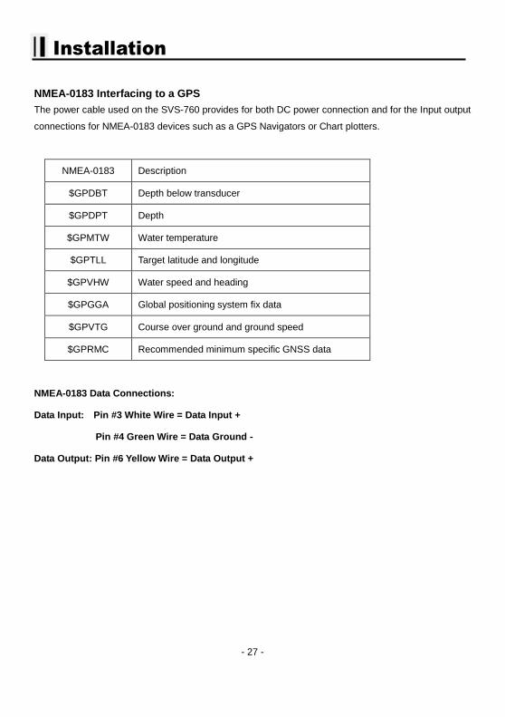
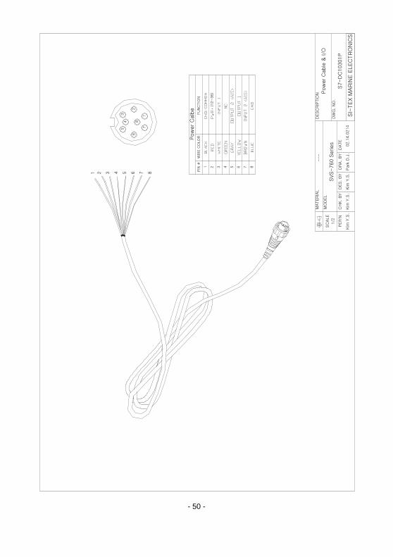
NMEA-0183 Interfacing to a GPS
The power cable used on the SVS-760 provides for both DC power connection and for the Input output
connections for NMEA-0183 devices such as a GPS Navigators or Chart plotters.
NMEA-0183 Description
$GPDBT Depth below transducer
$GPDPT Depth
$GPMTW Water temperature
$GPTLL Target latitude and longitude
$GPVHW Water speed and heading
$GPGGA Global positioning system fix data
$GPVTG Course over ground and ground speed
$GPRMC Recommended minimum specific GNSS data
NMEA-0183 Data Connections:
Data Input: Pin #3 White Wire = Data Input +
Pin #4 Green Wire = Data Ground -
Data Output: Pin #6 Yellow Wire = Data Output +
- 28 -
Operation of the SI-TEX SVS-760
Fishfinder Modes The SVS-760 Fishfinder modes are selectable for single frequency or dual frequency, and split screen
functions, for example bottom zoom or bottom lock.
FISH FINDER MODES
Normal 200khz
Bottom Zoom 200khz
Bottom Lock 200khz
Normal 50khz
Bottom Zoom 50khz
Bottom Lock 50khz
Normal 200/50khz
Bottom Zoom 200/50khz
▶ Pressing the [MODE] key allows you to selects the following choices:
1. Normal (200KHz or 50KHz)
Normal mode (with Auto Range active) displays the sounder image with the surface at the top of the
screen and the sea bottom in the lower part of the screen. The depth scale indicates the depth range
appearing in the display. Bottom contours and fish echoes are displayed at the depths where they are
detected. If the depth Range is set manually to a value less than actual water depth, sea bottom
echoes are not displayed, but all other echoes within the Range setting are displayed.
- 29 -
Operation
2. Bottom Zoom (200KHz or 50KHz) Bottom Zoom magnifies the sounder display from the sea bottom toward the surface for a short
distance. The sea bottom contour is displayed and additional contour lines are added at intervals
above the sea bottom to aid in determining distances of echoes near the bottom. Use the Sounder
Menu to set the magnified Bottom Range from 2.5 to 20m (10 to 60ft.). Default setting is 10m (40ft.). If
the depth Range is set manually, the setting must place the sea bottom echo in the lower portion of the
screen for Bottom Zoom to be effective.
3. Bottom Lock (200KHz or 50KHz) Bottom Lock divides the SVS-760 Fishfinder main screen image into two sections. The left hand
section displays a Normal Mode image. The right hand section of the screen displays the Fishfinder
image relative to the sea bottom. The sea bottom appears as a straight line with the Fishfinder image
magnified for a short distance toward the surface. A scale
appears on the right side of the screen for estimating distances of echoes near the bottom. Use the
Fishfinder Manu to set the magnified Bottom range from 10 to 60ft (2.5 to 20m). Default setting is 40ft
(10m) If the depth Range is set manually, the setting must place the sea bottom echo in the
lower portion of the screen for Bottom Lock to be effective.
Bottom Lock modes are selectable for single frequency or dual frequencies.
4. Normal Dual Frequency (200KHz and 50KHz) The high frequency (200KHz) displays on the left side and the low frequency (50KHz) displays on the
right side.
5. Bottom Zoom Dual Frequency (200KHz and 50KHz) The high frequency (200KHz) displays on the left and the low frequency (50KHz) Bottom Zoom
displays on the right.

- 30 -
Operation
Fishfinder
High Frequency
Depth bar
Low Frequency
Data bar
Red color : It is selected to
setup Frequency
- 31 -
Operation
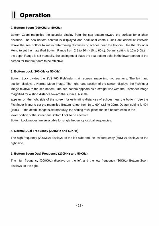
FF + Highway
The highway display provides a 3D view of own ship’s progress toward destination (waypoint).
Destination waypoint name
Destination
waypoint
Bearing from own
ship to destination
waypoint
Course Over
Ground
Range from own
ship to destination
waypoint Speed Over
Ground
XTE Alarm Radius
XTE of Vessel
XTE Alarm Radius
- 32 -
Operation
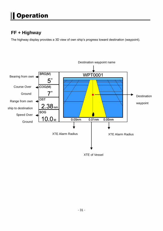
FF + Steering
The steering display provides steering information such as ship’s speed, course, range, bearing, TTG.
Destination waypoint
name
Bearing from
own ship to
destination
Speed Over Ground
Rang
from
own
ship to
destinati
on
Time-To-Go to destination
Bearing from own
ship to destination
waypoint Course Over Ground
Cross-Track-Error
- 33 -
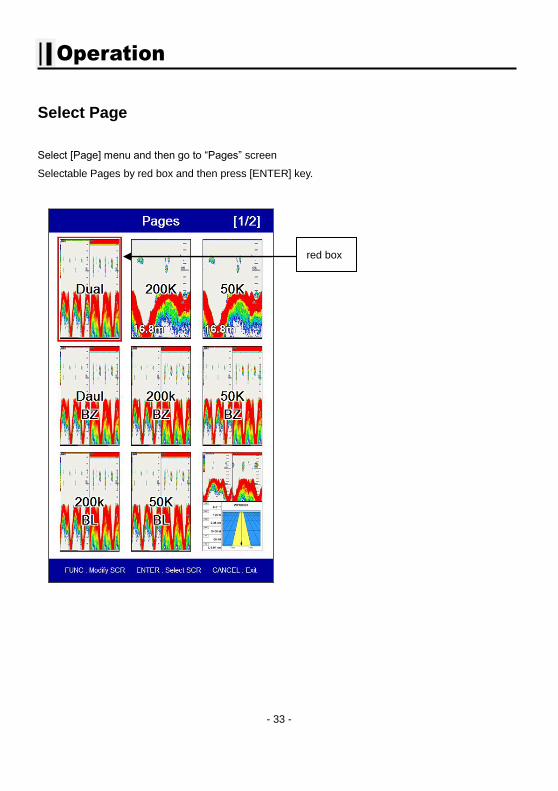
Operation
Select Page
Select [Page] menu and then go to “Pages” screen
Selectable Pages by red box and then press [ENTER] key.
red box
- 34 -
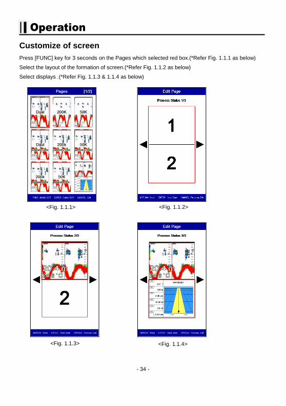
Operation
Customize of screen
Press [FUNC] key for 3 seconds on the Pages which selected red box.(*Refer Fig. 1.1.1 as below)
Select the layout of the formation of screen.(*Refer Fig. 1.1.2 as below)
Select displays .(*Refer Fig. 1.1.3 & 1.1.4 as below)
<Fig. 1.1.1> <Fig. 1.1.2>
<Fig. 1.1.3> <Fig. 1.1.4>
- 35 -
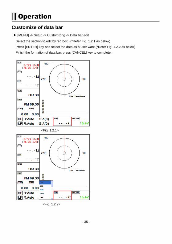
Operation
Customize of data bar
▶ [MENU] -> Setup -> Customizing -> Data bar edit
Select the section to edit by red box. .(*Refer Fig. 1.2.1 as below)
Press [ENTER] key and select the data as a user want.(*Refer Fig. 1.2.2 as below)
Finish the formation of data bar, press [CANCEL] key to complete.
<Fig. 1.2.1>
<Fig. 1.2.2>
- 36 -
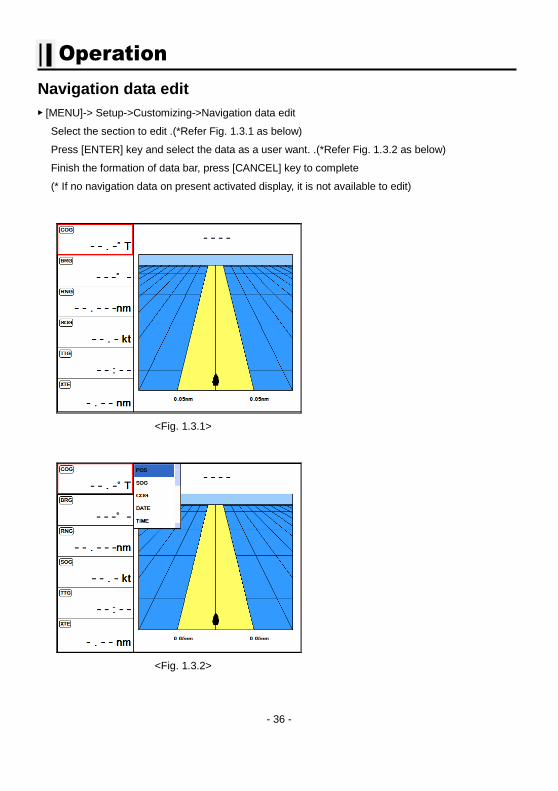
Operation
Navigation data edit
▶ [MENU]-> Setup->Customizing->Navigation data edit
Select the section to edit .(*Refer Fig. 1.3.1 as below)
Press [ENTER] key and select the data as a user want. .(*Refer Fig. 1.3.2 as below)
Finish the formation of data bar, press [CANCEL] key to complete
(* If no navigation data on present activated display, it is not available to edit)
<Fig. 1.3.1>
<Fig. 1.3.2>
- 37 -
Operation
Menu
The menu and explanation of operation are displayed.
▶ Press [MENU]
1. Range
JFC-7050 selects the best condition for measuring the depth automatically in the environment of the
sea.
(☞ The default setting is Auto.)
2. Shift
\A user selects this function to see more detailed bottom of the sea. When you turn up the shift, the
range of Sounder shall go up from the shift range. For example, if you raise 5m of shift at 20m range,
the surface shall start 5m and the bottom range shall be 25m.
(☞ The default setting is 0m.)
3. Display
3.1. A-Scope:
A-scope shows the research under the water by a scope to see the environment under the water.
(☞ The default setting is Off.)
3.2. Image Speed:
Select the speed of Sounder image from 4X until stop.
(☞ The default setting is 1X.)
3.3. White Line
It is necessary to research a detailed fish on the bottom or a seaweed under the sea. The color of the
bottom changes into white or black to see the bottom easier than red.
(☞ The default setting is OFF.)
3.4. Bottom Zoom Range
Select the range of the bottom zoom or lock. It is necessary to modify the bottom.
(☞ The default setting is 10m.)
- 38 -
Operation
3.5.Depth
3.5.1. Display
On/Off the depth range on the screen.
(☞ The default setting is ON.)
3.5.2. Depth Font
Select the depth range font size on the screen.
(☞ The default setting is Normal.)
3.6.TEMP
3.6.1. Display
On/Off the temperature on the screen.
(☞ The default setting is Off.)
3.6.2. TEMP Font
Select the temperature font size on the screen.
(☞ The default setting is small.)
3.7. Speed
3.7.1. Display
On/Off the speed on the screen.
(☞ The default setting is Off.)
3.7.2. .Speed Font
Select the temperature font size on the screen.
(☞ The default setting is normal.)
3.8. Frequency Display
It is available to setup the place of high/low frequency on dual display.
(☞ The default setting is 50KHz/200KHz.)
3.9. Fish
- 39 -
Operation
3.9.1. Symbol
Fish symbol with sizes and levels show for targets.
(*Fish symbol is only for reference. This could be different from the real.)
(☞ The default setting is Off.)
3.9.2. Size
Display the size of fish on the window
(*Fish size is only for reference. This could be different from the real..)
(☞ The default setting is Off.)
3.9.3. Size unit
Set up the unit(cm, inch) of displayed size of fish on the screen
(☞ The default setting is centimeter.)
4. Rejection
4.1. Interference Rejection (from engine)
When there are another boats around you on sailing, your sounder could be disturbed to work. The
step of the function is from off to level 2. The bigger number, the more rejection.
(☞ The default setting is OFF.)
4.2. Noise Rejection
Your Echo sounder could be disturbed by the engine noise. This function can reject the noise from
the engine or other machinery instruments.
(☞ The default setting is OFF.)
5. Color
5-1. Bottom color level
This function adjusts the colors. Make it upper level, the color becomes darker.
(☞ The default setting is 0.)
5-2. Color Rejection
There are 16 color levels for Echo sounder. The color bar is on the left of the Echo sounder. If the
level is higher, the color of the bar is deleted one by one.
5-3. Screen Color
Select the back ground color of the Echo sounder for your convenience.
- 40 -
Operation
6. Pulse
Select the pulse of the output from the transducer. Levels are among Low, Medium and High, which
depends upon the depth. Low is proper to research precise a fish school but it is not suitable to
measure a deep depth. High is opposite from Low.
(☞ The default setting is Medium.)
7. Output Power
Select the output from the installed transducer. Levels are from off to 3. It should be careful about
the depth. If you set high level in a sallow depth, the Fish finder screen turns to red. You see
nothing expect red on the screen.
(☞ The default setting is 3.)
8. Alarm
8.1. Depth
8.1.1. Deep Alarm
It alarms when the set deep depth is out of the range.
(☞ The default setting is OFF.)
8.1.2. Deep range
Setup the range of deep depth alarm
(☞ The default setting is 0M.)
8.1-3. Shallow alarm
It alarms when the set shallow depth is out of the range.
(☞ The default setting is OFF.)
8.1-4. Shallow range
Setup the range of shallow depth alarm
(☞ The default setting is 0M.)
8.2. TEMP(Temperature)
8.2.1. High alarm
It alarms when the set high temperature is out of the range.
(☞ The default setting is OFF.)
- 41 -
Operation
8.2.2. High Range
It alarms when the set high temperature is out of the range.
(☞ The default setting is 0.)
8.2.3. Low alarm
It alarms when the set low temperature is out of the range.
(☞ The default setting is OFF.)
8.2.4. Low range
It alarms when the set low temperature is out of the range.
(☞ The default setting is 0.)
8.3. Fish-School
8.3.1. Alarm
It alrams when it detects school of fish.
It will detect school of fish depend on set depth, range and level of the Echo sounder.
(☞ The default setting is OFF.)
8.3.2. Fish-school Depth
If the alram is on, It is available to setup the depth of the Fish-school
(☞ The default setting is 10m.)
8.3.3.Alarm range
If the the alram is on, It is available to setup the Range(hight) of the Fish-school.(The bar, next of
display is shown)
(☞ The default setting is 50m.)
8.3.4. Alarm Interval
If the the alram is on, It is available to setup the alarm interval.
(☞ The default setting is middle)
8.3.5. Color Level
If the the alram is on, It is available to setup the color level.
It is available to setup the color level
- 42 -
Operation
9. Setup
9.1. System
It contains ID and the program version, and it has important information for maintenance and upgrade.
9.2. Unit
9.2.1. Distance/Speed
Select desired unit of measure for distance and speed. Choose from: nautical mile/knots (nm/kt),
kilometer/kilometers per hour(km/kmh), yard/knot(yd/kt).
cf) 1nm = 1.852km, 1kt /h= 1.852km/h, less than 1nm display in yard and over 1nm display in mile
(☞ The default setting is Nm/Kt.)
9.2.2. Depth
Select desired unit of measure for depth of water. Choose from: meter(M), foot(ft), fathom(fm),
Italian Fathom(Ifm), Japanese fathom(Jfm).
cf) 1m = 3.281ft = 0.549fm = 0.609lfm = 0.660jfm
(☞ The default setting is Meter.)
9.2.3. Temperature
Select desired unit of measure for temperature of water. Choose from: Celsius(℃), or Fahrenh
eit(℉).
cf) 1℃ = +32℉
9.3. Time/Date
9.3.1. Reference
Available to adjust the collect local time by the UTC time from the GPS.
(☞ The default setting is incorrect every the country.)
9.3.2. Time format
Sets you preferred time between 12 hour and 24 hour.
(☞The default setting is 12 hour.)
9.3.3. Date Format
Sets you preferred date among YY-MM-DD, MM-DD-YY or DD-MM-YY.
(☞ The default setting is YY-MM-DD.)
9.3.4. Month format
Setup the character of month(Ex: 1, 2, 3…or JAN, FEB, MAR…)
- 43 -
Operation
9.4. Input/Output
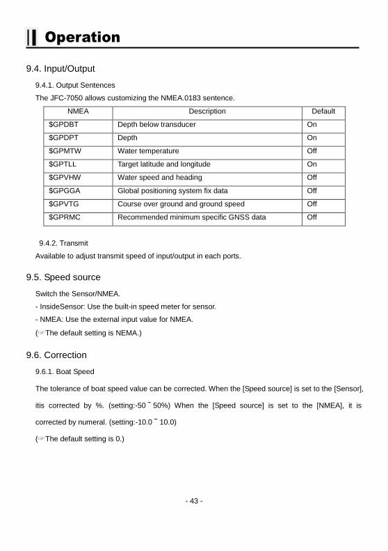
9.4.1. Output Sentences
The JFC-7050 allows customizing the NMEA.0183 sentence.
NMEA Description Default
$GPDBT Depth below transducer On
$GPDPT Depth On
$GPMTW Water temperature Off
$GPTLL Target latitude and longitude On
$GPVHW Water speed and heading Off
$GPGGA Global positioning system fix data Off
$GPVTG Course over ground and ground speed Off
$GPRMC Recommended minimum specific GNSS data Off
9.4.2. Transmit
Available to adjust transmit speed of input/output in each ports.
9.5. Speed source
Switch the Sensor/NMEA.
- InsideSensor: Use the built-in speed meter for sensor.
- NMEA: Use the external input value for NMEA.
(☞The default setting is NEMA.)
9.6. Correction
9.6.1. Boat Speed
The tolerance of boat speed value can be corrected. When the [Speed source] is set to the [Sensor],
itis corrected by %. (setting:-50~50%) When the [Speed source] is set to the [NMEA], it is
corrected by numeral. (setting:-10.0~10.0)
(☞The default setting is 0.)
- 44 -
Operation
9.2.5. Water Temp
The error of water temp value can be corrected.
(setting:-10.0~10.0℃,-10~10°F)
(☞The default setting is 0.)
9.2.6. Draft set
The tolerance of depth can be corrected. Set the depth from the sea level to the set depth of your
transceiver/receiver. Normally set draft value of your boat.
(setting 0~20m)
(☞The default setting is 0.)
9.7. Image Filtering
This function is reduction of the noise.
(☞ The default setting is OFF.)
9.8. Buzzer
It is can be sound on/off.
(☞ The default setting is on.)
9.9. Simulator:
It is necessary for an indoor demonstration. The simulations of Fish finder in the memory..
9.10. Customizing
9.10.1. Databar
9.10.1.1. Display
Setting up shown/hide the databar on the display.
(☞ The default setting is Shown.)
9.10.1.2. Position
Setting up up/down the position of databar on the display.
(☞ The default setting is Down.)
- 45 -
Operation
9.10.1.3. Edit
It customizes the data bar information.
9.10.1.4 Mode
It is available to set up the data bar.
- Customizing : It is selectable and modifiable the data bar by user.
- Fix mode : It is fixed data bar by default. It is not available selectable and modifiable the data
bar by user.
(☞ The default is User mode.)
9.10.2. Navigation Data
9.10.2.1. Type
It is a select the navigation data type.
(☞ The default setting is Type1.)
9.10.2.2. Edit
It customizes the Navigation data section except activated the echo sounder section.
9.10.3. Page mode
It is a select the page mode.
- Standard: Choosing Page and customizing is available.
- Flip: Showing the chosen pages in order.
(☞ The default setting is Standard.)
9.11. Language:
Select the language.
9.12. Initialization
9.11.1.Setup Initialization : reset without deleting user data.
9.11.2.Factory Initialization] : returning to the initial system from the releasing of factory.
(*All user data will be deleted)
- 46 -
Operation
10. Others
10.1. Key Setup
It is available to set up [FUNK] key and [EVENT] key on the JFC.7050.
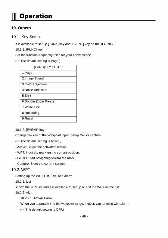
10.1.1. [FUNC] key:
Set the function frequently used for your convenience.
(☞ The default setting is Page.)
[FUNC]KEY SETUP
1.Page
2.Image Speed
3.Color Rejection
4.Noise Rejection
5.Shift
6.Bottom Zoom Range
7.White Line
8.Recording
9.Reset
10.1.2. [EVENT] key:
Change the key of the Waypoint input, Setup Nav or capture.
(☞ The default setting is Active.)
- Active: Select the activated section.
- WPT: Input the mark on the current position.
- GOTO: Start navigating toward the mark.
- Capture: Store the current screen.
10.2. WPT
Setting up the WPT List, Edit, and Alarm.
10.2.1. List
Shown the WPT list and it is available to set up or edit the WPT on the list.
10.2.2. Alarm
10.2.2.1. Arrival Alarm:
When you approach into the waypoint range, it gives you a notice with alarm.
(☞ The default setting is OFF.)
- 47 -
Operation
10.2.2.2. Arrival Radius:
It is to adjust the range of arrival from your waypoint. If you have a route, it changes to the next
waypoint automatically.
(☞ The default setting is 0.05nm.)
10.2.2.3. XTE Alarm:
If you are out of the course, it gives you a notice with alarm.
(☞ The default setting is OFF.)
10.2.2.4. XTE Radius:
It is to adjust the range of the off course.
(☞ The default setting is 0.05nm.)
10.2.3. Navigating Stop
Stops the present navigation.
10.2.4. Save WPT
You can save the WPT in SD card.
10.2.5. Load WPT
You can load the WPT from SD card.
10.3. Recording
This is the function of recording current screen.
Marked [● REC] in red color on the upper right on the data bar during recording.
Note: The recording file is stored in external memory cards, SD memory. Check SD memory in the
JFC-7050.
(* Recording time is different by the size of the memory card)
10.4. Recording List
Available to display and delete the recording file
10.5. Capture
This is the function of Screen Capture.
Note: The recording file is stored in external memory cards, SD memory. Check SD memory in the
JFC-7050.

- 48 -
Operation
10.6. Capture List
Available to display and delete the capture file
10.7. Page
Select the configuration & modification you wish.
10.8. Active
Select the activated section.
- 49 -
Operation
VRM
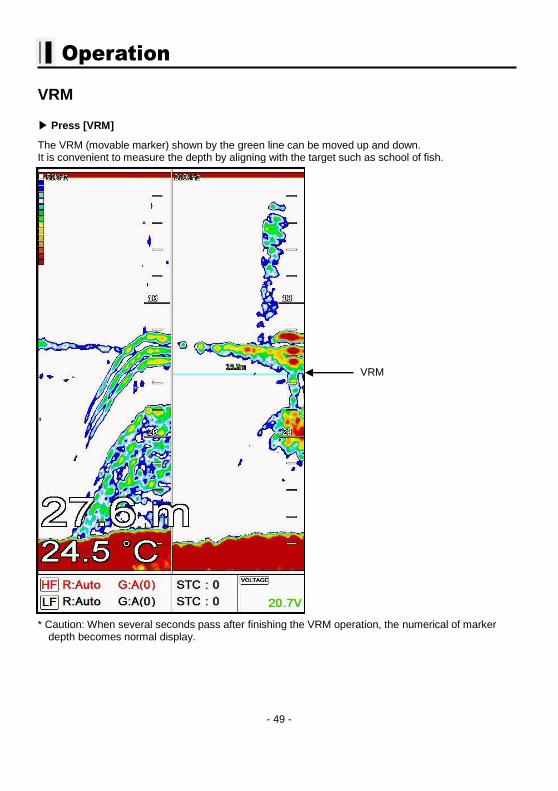
▶ Press [VRM]
The VRM (movable marker) shown by the green line can be moved up and down. It is convenient to measure the depth by aligning with the target such as school of fish.
* Caution: When several seconds pass after finishing the VRM operation, the numerical of marker depth becomes normal display.
VRM
- 50 -
62
54
3
7
8
1
85 6 7431 2
(12~
36)
FU
NC
TIO
NPIN
#W
IRE C
OLO
RPow
er
Calb
e
2 43 5 76 81
Kim
Y.S
.Kim
Y.S
.Kim
Y.S
.
DR
A.
BY
Park
D.J
.
SVS-760 S
eries
CH
K.
BY
PER
'ND
ES.
BY
MO
DEL
MATER
IAL
SC
ALE
1/2
02.1
4.0
214
DATE
SI-
TEX M
AR
INE E
LEC
TR
ON
ICS
S7-D
C10301P
DESC
RIP
TIO
N---
DW
G.
NO
.
Pow
er
Cable
& I/O
- 51 -
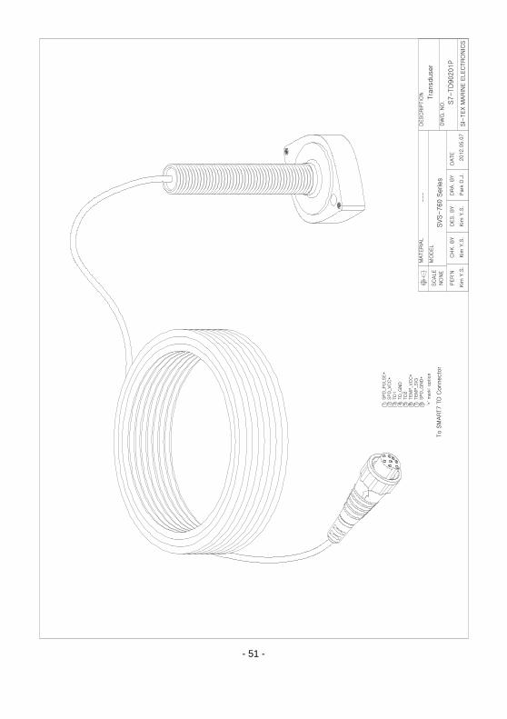
Tra
nsduser
1
SPD
_PU
LSE*
2
SPD
_VC
C*
3
TD
14
TD
_G
ND
5
TD
26
TEM
P_VC
C*
7
TEM
P_SIG
8
SPD
_G
ND
*
To S
MAR
T7 T
D C
onnecto
r
S7-TD
90201P
Kim
Y.S
.Kim
Y.S
.Kim
Y.S
.
DRA.
BY
Park
D.J
.
CH
K.
BY
PER'N
DES.
BY
2012.0
5.0
7
DATE
DW
G.
NO
.
---
DESC
RIP
TIO
N
NO
NE
SC
ALE
MATERIA
L
MO
DEL
SVS-760 S
eries
'*' m
ark
: option
SI-
TEX M
ARIN
E E
LEC
TRO
NIC
S
- 52 -
Kim
Y.S
.Kim
Y.S
.Kim
Y.S
.Park
D.J
.
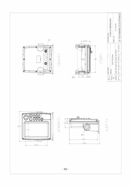
S7-PL00D
P
SVS-760 S
eries
DESC
RIP
TIO
N
DW
G.
NO
.
DES.
BY
NS
SC
ALE
PER'N
MO
DEL
CH
K.
BY
MATERIA
L
DRA.
BY
---
SI-
TEX M
AR
INE E
LEC
TRO
NIC
S
DATE
02.1
6.2
014
PLAN
& D
IMEN
SIO
NS
62
54
3
7
8
1
6
2
54
3
7
8 1

- 53 -

- 54 -
- 55 -
CERTIFICATE OF LIMITED WARRANTY
Providing you present a valid proof of purchase, SI-TEX Marine Electronics Inc. warrants all parts of
each new product against defects in material and workmanship under normal use and will repair or
exchange any parts proven to be defective at no charge for a period of two years for parts and one
year for labor from the date of purchase, except as provided below under Limited Warranty Exceptions.
Defects will be corrected during normal working hours by an authorized SI-TEX Marine Electronics Inc.
dealer, service center, or at the SI-TEX office in Riverhead, NY. There will be no charge for labor for a
period of one year from the date of purchase, except as provided below under Limited Warranty
Exceptions.
This Warranty and Proof of Purchase must be made available to the authorized SI-TEX Marine
Electronics Inc. service location or dealer at the time of service.
LIMITED WARRANTY EXCEPTIONS
SI-TEX Marine Electronics Inc. will not be responsible for equipment which has been subjected to
water or lightning damage, accident, abuse, or misuse, nor any equipment on which the serial number
label has been removed, altered or mutilated.
SI-TEX Marine Electronics Inc. assumes no responsibility for damage incurred during installation.
This Limited Warranty is effective only with respect to the original purchaser.
Any cost associated with transducer replacement, other than the cost of the transducer itself, is
specifically excluded from this Limited Warranty.
Travel costs incurred will not be accepted for SI-TEX Marine Electronics Inc. products.
THERE ARE NO WARRANTIES, WHICH EXTEND BEYOND THE DESCRIPTION OF THE FACE
HEREOF.
- 56 -
SPECIFIC EXCLUSIONS
Charges for overtime, stand-by, holiday, and per diem are specifically excluded from the Limited
Warranty. Installation workmanship or materials except as provided directly by SI-TEX Marine
Electronics Inc. are not covered by this Limited Warranty. SI-TEX Marine Electronics Inc. equipment
or parts thereof, which have been repaired or altered except by an authorized SI-TEX Marine
Electronics Inc. dealer or service center, are not warranted in any respect. Transducer, software
update, battery, microphone, magnetron, and microwave components and water damage on water
resistant VHF radio are items excluded from the two-year warranty and are covered by warranty for a
period of one year for both parts and labor. SI-TEX Marine Electronics Inc. will not, at any time,
assume any costs or labor charges for checkout or external line fuse replacement or problems not
found to be at fault in equipment itself.
THERE ARE NO WARRANTIES OR GUARANTEES EXPRESSED OR IMPLIED WHICH EXTEND
BEYOND THE DESCRIPTION ON THE FACE HEREOF, INCLUDING WARRANTIES OF FITNESS
FOR A PARTICULAR PURPOSE AND MERCHANTABILITY. SI-TEX MARINE ELECTRONICS INC.
HAS NO OTHER LIABILITY TO PURCHASE FOR DIRECT OR CONSEQUENTIAL DAMAGE OR
ANY THEORY INCLUDING ABSOLUTE LIABILITY, TORT, OR CONTRACT. THIS LIMITED
WARRANTY CANNOT BE ALTERED OR MODIFIED IN ANY WAY AND SHALL BE INTERPRETED
IN ACCORDANCE WITH THE LAWS OF THE STATE OF NEW YORK. THIS WARRANTY IS
LIMITED TO THE CONTINENTAL U.S.A., ALASKA, HAWAII, AND CANADA.
- 57 -
HOW TO OBTAIN SERVICE UNDER THIS WARRANTY
If you encounter problems during the installation or operation of this product, or cannot find the
information you need, please contact SI-TEX Customer Service.
The contact numbers and e-mail address for SI-TEX Customer Service are:
SI-TEX Main Office…….………..+1-631-996-2690
SI-TEX Fax..………………….…..+1-631-996-2693
SI-TEX Service E-mail address: [email protected]
SI-TEX Customer Support E-mail address: [email protected]
SI-TEX Main Office Address:
25 Enterprise Zone Drive, Ste 2
Riverhead, NY 11901
Technical Support is available from 9:00 AM to 5:00 PM Eastern Standard Time, Monday through
Friday.