sweden - · pdf file4.2 tps termiska processer ab ... 6.2.2 the tps/ansaldo rdf gasification...
TRANSCRIPT

May 2008
Report on Biomass Gasification Activities in Selected Countries
Sweden April 2008
1 General Overview ..................................................................................................................... 42 2 Policy ......................................................................................................................................... 43
2.1 Capital investment grants .................................................................................................. 43 2.2 Targets of energy policy ................................................................................................... 43
2.3 Fuel and energy prices ...................................................................................................... 46
2.4 Taxes, levies and fees ........................................................................................................ 48
2.5 Other non-fiscal instruments ............................................................................................. 51 2.5.1 Green electricity certificates .................................................................................. 51
2.5.2 Emission rights trading .......................................................................................... 52
2.5.3 Renewable transport fuel certificates .................................................................... 52
3 Activities in Biomass Gasification R&D Programs .................................................................. 52 4 R&D Institutes/Organisations ................................................................................................... 53
4.1 Royal Institute of Technology (Kungliga Tekniska Högskolan, KTH) - www.kth.se ...... 53
4.2 TPS Termiska Processer AB (TPS) - www.tps.se ............................................................ 55
4.3 Lund University (LTH) - www.lth.se ............................................................................... 57 4.4 Växjö University (VXU) - www.vxu.se ........................................................................... 58
4.5 MittUniversitetet - www.miun.se ...................................................................................... 58
4.6 Umeå University (UmU) - www.umu.se .......................................................................... 59
4.7 Luleå Technical University (LTU) - www.luth.se ............................................................ 59 4.8 Energy Technology Center (ETC), Piteå - www.etcpitea.se............................................. 59
4.9 Chalmers Technical University (CTU) - www.chalmers.se ............................................. 60
4.10 Mälardalens Högskola - www.mdh.se .............................................................................. 62
4.11 Svenskt Gastekniskt Centrum (SGC) - www.sgc.se ......................................................... 63 5 Industrial Biomass Gasification Activities, 1997-2006............................................................. 63
5.1 General overview .............................................................................................................. 63
5.2 Downdraft gasifiers ........................................................................................................... 65
5.3 Updraft gasifiers ................................................................................................................ 65 5.4 CFB gasifiers .................................................................................................................... 65
5.5 Power generation with biomass gasification ..................................................................... 65
5.6 Waste gasification ............................................................................................................. 66
5.7 Black liquor gasification ................................................................................................... 66 5.8 Synthesis gas for liquid fuels and SNG............................................................................. 67
6 Technology Implementation and Plant and Projects ................................................................. 68
6.1 Commercial plants before 1990 (not in operation today) ................................................. 68 6.2 Commercial plants in operation after 1990 or still in operation ....................................... 68
6.2.1 The Värö plant ....................................................................................................... 68
6.2.2 The TPS/Ansaldo RDF Gasification Process - Grève-in-Chianti plant ................. 71
6.3 Development activities ...................................................................................................... 73 6.3.1 The VEGA project ................................................................................................. 73
6.3.2 The BIOFLOW (Sydkraft/Foster Wheeler) concept in Värnamo ......................... 74
6.3.3 The CHRISGAS project - www.chrisgas.com ...................................................... 81
1

May 2008
Report on Biomass Gasification Activities in Selected Countries
6.3.4 The TPS gasification and hot gas cleaning process - incl. ARBRE plant ............. 86
6.3.5 Chemrec - www.chemrec.se .................................................................................. 96 6.3.6 Scanarc/Pyroarc (plasma) process - www.scanarc.se .......................................... 102
2

May 2008
Report on Biomass Gasification Activities in Selected Countries
2 GENERAL OVERVIEW
On-going industrial and academic activities on biomass gasification within Sweden are
summarised in Figure 2.
ETC, R&D
Chemrec, 3 MW demoBlack liquor gasificationPiteå
Mid-Sweden University
Indirect double bed test unitHärnösand
F-W 20 MW CFB gasifierNorrsundet/lime kiln
KTH, gasification and F-T studies
Tar/iron catalysis HTAGStockholm
Bioneer 6 MWFixed bed updraft gasifier
Vilhelmina
TPS, R&D and FB gasifier
Nyköping
BIOFLOW PCFBG
VVBGC demoVärnamo
Metso (Götaverken)
35 MW CFB gasifierVarö lime kiln
E.ON Sweden
SNG or IGCC Study for 50 MW unit
CTH system studies
2 MW indirect gasifier CFB coupling F-T R&D
Göteborg Energi SNG study 200 MW
Gothenburg
Umeå Universitet, R&D
ash sintering, tar reduction,
indirect gasification process dev.
Pilot or demo
R&D
Commercial
Figure 2 The 2008 biomass gasification map of Sweden
3

May 2008
Report on Biomass Gasification Activities in Selected Countries
3 POLICY
The state organisation responsible for energy issues in Sweden is the Swedish National
Energy Agency (STEM), Box 310, 63 104 Eskiltuna. Telephone: +46 16 544 2000.
E-mail: [email protected]. Website: www.swedishenergyagency.se/.
In 2003, an independent group of investigators evaluated the Swedish energy R&D
programme. The verdict was that the quality of the work was generally good, but that
measurable deployment of results in society or by industry was low. This deficiency was
claimed to be the result of extended time to implement R&D results into products. This
resulted in a re-orientation from the earlier more dominant basic research to more applied
research and development.
The new aim of STEM is to establish an ecologically and economically sustainable
energy system by:
Supporting R&D on renewable energy sources,
Focusing on R&D that has a short to mid-term societal impact and
Facilitating the exploitation of the results of the R&D programme
The latter two have been gaining in importance whilst knowledge generation in general
terms and basic research has lost ground.
3.1 Capital investment grants
No general grants for installing biomass renewable energy systems have been available
since 2002. Instead, the trading of national Renewable Electricity Certificates and EU-
harmonised Emission Rights are seen to provide additional revenues, replacing that from
investment support. However, for demonstration projects and prototypes, some grant
financing can be made available from the R&D budget, which has been reinforced to also
cover this stage in development.
3.2 Targets of energy policy
Energy policies enacted in the 1960’s still have a bearing on the Swedish situation when
the decision on the programme of rapid expansion of nuclear power was taken, this led to
the construction and commissioning of twelve nuclear power plants in the early 1980’s.
The oil crisis in the 1970’s and 1980’s resulted in a rapid change over from fuel oil to
other fuels including also an increased use of coal.
In the 1970’s, the nuclear programme was debated increasingly, and after the Harrisburg
accident, the labour party government consented to a referendum on the future of nuclear
energy. The referendum held in 1978 decided that nuclear power should be phased out
completely by 2010, starting in 1986. Public distrust in the referendum decision being
honoured led to a law in the beginning of the 1980’s that prohibited development of
nuclear reactors and the engineering of new plants.
4

May 2008
Report on Biomass Gasification Activities in Selected Countries
From the late 1980’s, the goal of the energy policy became two-fold, to replace both
fossil fuels and nuclear power. This led to a policy of promoting renewable power and
heat, as manifested by the introduction in 1991 of environmental taxation and an
investment grant scheme that was ended in 2002.
In 1996, the electricity market was deregulated, followed by successive changes to
metering requirements and other legal aids to also allow household customers to choose
the type of contract and supplier.
In 1997, a new energy policy was agreed for Sweden. The objective of the energy policy
was to ensure, in both the short- and long-terms, a reliable supply of electricity and other
forms of energy on competitive terms. As part of this program, the nuclear reactors,
Barsebäck 1 and 2, were phased out in 2002 and 2005, respectively. No additional phase-
outs are planned for the foreseeable future. Furthermore, an effort to arrange a phase out
programme by negotiations with the owners of nuclear power plants (similar to that used
in Germany, whereby the total production is capped and the plants can be phased out
according to lifetime and economic considerations) failed. At present, the consensus is
that phase out by 2010 is not possible. Both the Finnish decision in 2003 to construct a
new nuclear power plant and the increasing focus on the climate issue has resulted in a
new debate on nuclear power.
A new energy policy agreement for Sweden, under the name “Working Together for a
Reliable, Efficient and Environmentally Aware Energy Supply” was put in place in 2002.
In this agreement, changes are concerned primarily with the thrust of the guide measures
intended to influence developments in the shorter term. The agreement incorporates a
longer-term element intended to restructure the energy system through encouragement of
electricity production from renewable sources and of more efficient use of energy. A new
guide measure, in the form of trading in Renewable Electricity Certificates, was
introduced in 2003 in order to encourage the production of electricity from renewable
sources with minimum environmental impact. This guide measure replaced the earlier
25% general capital grant scheme for renewable plants, and had a life-time lasting until
2012, which has now been prolonged to 2030, however with the limitation that plants can
only be beneficiaries of certificates of electricity for a period of 15 years.
The so-called flexible mechanism for CO2 was introduced in the climate change bill that
stated that Sweden would decrease the emissions of greenhouse gases by 4% of the level
in 1992 by 2012. This implies joint implementation projects in Eastern Europe, five
CDM projects and, as mentioned earlier, also trading of emission rights from 2005 within
the EU Emissions Trading Scheme (ETS). A number of changes to the tax structure have
also been made to equalise the taxation between sectors and allow taxation of CHP
plants, and also to harmonise with the EC gas and electricity market directives.
As a result of proposed tax changes, the introduction of natural gas has been strongly
advocated recently. One large combined cycle co-generation plant went into operation in
Gothenburg in 2006, and another one in Malmö by E.ON is in the construction stage.
5

May 2008
Report on Biomass Gasification Activities in Selected Countries
In 2003, the Swedish Government introduced a pilot scheme to introduce biofuels in the
transport sector by allowing tax and duty exemptions for quota imports of such fuels,
notably ethanol and RME (rape methyl ester), this scheme originally being valid up to
2008, but in 2006 prolonged to 2011. An investigator concluded that Sweden, mainly by
the use of imported ethanol, would not only meet the EU target of 2% in 2005 but would
exceed it by 1%, but that the 2010 target of 5.75 % would require new measures to be
taken. The investigator also emphasised the need for RD&D in second generation
biofuels, including oxygen-blown gasification to synthesis gas, as this is a key technology
to accomplish policy targets.
The climate issue was very much in focus in the earlier part of 2006. The STEM R&D
budget was increased to approx. 90 million euro per year (Figure 3), and explicitly stated
that R&D activities, in particular in the biofuel area, should be pursued to the
demonstration phase. A high level Commission for Oil Substitution, chaired by the labour
prime minister and also including industrial and other stakeholders, recommended that
most use of fossil fuel should be abandoned by 2020 through strong promotion of
renewable energy and energy, avoiding the use of oil in heating systems and replacing up
to 20% of the automotive fuels with biofuels.
Figure 3 Funding for research, development and demonstration activities
6

May 2008
Report on Biomass Gasification Activities in Selected Countries
Following the change in parliamentary majority in the 2006 election, the labour minority
government was replaced by a four party liberal conservative coalition. One of the
compromises of the new majority, as the coalition includes both heavily pro- and anti-
nuclear parties, was to postpone further discussion on nuclear power policies to 2010.
The low-profile of these parties with regard to climate and environmental issues, in
relative terms, has changed during the first year in power. The Commission for Oil
Substitution has been substituted by a “Sustainability Commission”, and several concrete
tax changes and other measures has been proposed for the 2008 budget, see below.
Furthermore, a “climate billion” was singled out in the 2008-2010 budget, i.e. one billion
Swedish crowns (SEK) for climate change mitigation purposes. Of this sum, 50 million
SEK per year (€5.5 million) was allocated under the heading “biofuel production pilot
and demonstrations”.
3.3 Fuel and energy prices
The price of different fuels in Sweden, as of 2006, for various customers is given in
Figure 4. Table 1 shows the price of wood fuels in Sweden for various customers.
Source: Swedish Petroleum Institute, Statistics Sweden, ÄFAB, National Tax Board
Note. Prices shown for industry do not include any large-user discounts. The share of taxes are given within
brackets
Figure 4 Total energy prices for various user categories, 2006 (1 SEK = 100 öre ~
0.11€)
(www.swedishenergyagency.se/web/biblshop_eng.nsf/frameset.main?ReadForm&Doc=)
Table 1 Price of wood fuel in Sweden, excluding VAT, SEK/MWh
7

May 2008
Report on Biomass Gasification Activities in Selected Countries
Period 2004 2005 2006 2007 P
All
Sweden
North Central South
Briquettes and pellets
Heating plants 206 204 211 244 277 256 230
Forest wood chips
Industry 125 121 119 128 -1 -
1 -
1
Heating plants 138 137 146 158 167 163 142
Bi-products
Industry 112 95 112 153 -1 -
1 -
1
Heating plants 114 121 128 134 128 140 127
Recycled wood
Heating plants 74 80 78 64 -2 69 51
1) the regional data includes only that from heating plants. Note that the average price in the regions are
more uncertain than the average price for the country
2) too few data to include in table
P) preliminary data
The rise in the price of energy in Sweden that occurred from the early 1970’s to the mid.
1980’s was mainly due to the increase in the price of oil, whilst the rise since then is
primarily the result of higher taxation, see below.
It is worthwhile to note that the price of electricity for the industrial sector has been stable
and low (€20-30/MWh) for a long period, this being a result of the production system,
deregulation, grid interconnections and last but not least, the policy of not enforcing the
same taxes and levies on industry as on other sectors. However, in 2006, prices rose
sharply, partially because of lack of rainfall in Scandinavia and partially because the
marginal cost system and energy transiting from Europe and Denmark made the Emission
Rights cost spill directly into the dominantly hydro and nuclear generation countries of
Finland, Norway and Sweden. Prices of two or three times above long-term averages
were experienced during the spring and summer of 2006 but gradually fell to € 40-
45/MWh, resulting in very good margins for the power industry These events led to a
fierce debate led by the main raw material industries and consumer organisations as both
saw their power bill rising on the deregulated electricity trading system and how it works.
For biomass CHP, the additional revenues for RE Certificates have given very good
economic margins, even periodically leading to operation with artificial heat loads.
The price of wood fuel has been stable in nominal terms since the beginning of the
1980’s, which means that the price in real terms has been falling over the last two
decades until recent years when an increase of 50% or more was seen. The demand has
increased with the increase in oil prices, taxes, electricity prices, and also the relatively
high profitability of co-generation plants in view of the high electricity prices and the
extra revenue from certificates. The forest industry has voiced strong concerns about the
consequences of competition between the forestry industries and the energy sector for
raw materials, while also being actors in this market place.
8
May 2008
Report on Biomass Gasification Activities in Selected Countries
3.4 Taxes, levies and fees
During the oil crises of the 1970’s, the aim of the taxation policy was to reduce the use of
oil and increase the use of electricity. The environmental element of energy taxation was
given greater importance in the beginning of the 1990’s and was introduced in 1991,
mainly with the purpose of reducing greenhouse gas emissions. Since Sweden’s
accession to the EU, there has subsequently been a need to bring taxation into line with
EU requirements, and in recent years this has provided the drivers to various studies and
proposals.
Present energy taxation policy is aimed at improving the efficiency of energy use,
encouraging the use of biofuels, creating incentives for companies to reduce their
environmental impact and creating favourable conditions for indigenous production of
electricity.
The present energy taxation system is relatively complex. There are different taxes on
electricity and fuels, on CO2 and sulphur emissions, and a levy system on NOx
emissions. The taxes can then vary, depending on whether the fuel is being used for
heating or as a motor fuel, whether it is being used by industry, domestic consumers or
the energy sector and, in the case of electricity, whether it is being used in northern
Sweden or in the rest of the country (Table 2). Value added tax on energy was introduced
in 1990, and is presently levied at a rate of 25%, but is deductible for companies and
industry.
The general energy tax, which has existed for several decades, is payable on most fuels,
and is independent of their energy content.
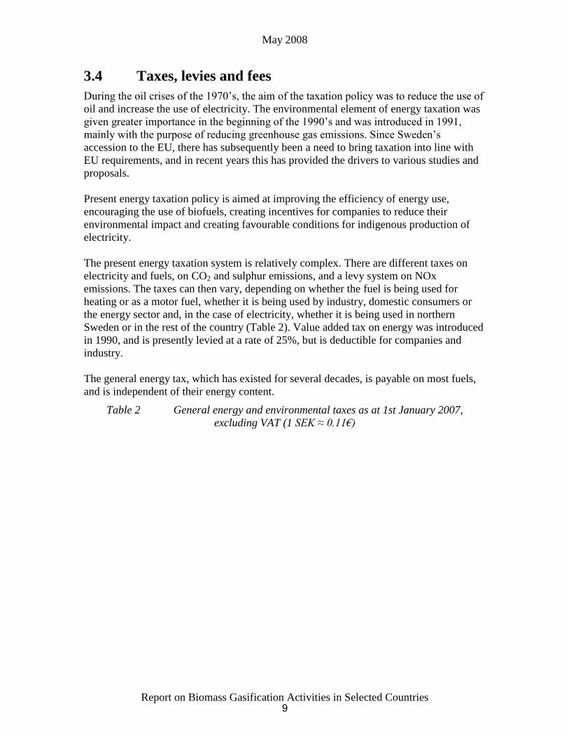
Table 2 General energy and environmental taxes as at 1st January 2007,
excluding VAT (1 SEK ≈ 0.11€)
9

May 2008
Report on Biomass Gasification Activities in Selected Countries
The CO2 tax, which was introduced in 1991, is levied on the emitted quantities of CO2
from all fuels apart from biofuels and peat. In 2003, the general level of CO2 tax was
0.76 SEK/kg of CO2. The CO2 tax on fuels was raised by 19% on 1 January 2003, which
was intended to increase its impact in relation to the energy tax, and to help to reduce
CO2 emissions. A simultaneous change in the tax reduction rules has had the effect of
ensuring that CO2 tax remains unchanged for manufacturing industry, etc.
A sulphur tax was introduced in 1991, and is levied at the rate of SEK 30 per kg of
sulphur emission from coal and peat, and at 27 SEK for each tenth of a percent by weight
of sulphur in oil.
The environmental levy on the emission of NOx was introduced in 1992 at a rate of
40 SEK/kg of NOx emissions from boilers, gas turbines and stationary combustion plant
supplying at least 25 GWh per annum. However, it is intended to be fiscally neutral, and
is repaid to plant operators in proportion to their energy production and in inverse
proportion to their NOx emissions so that only those with the highest emissions are net
payers. The system therefore provides a strong financial incentive for investments in
equipment intended to reduce NOx emissions. For fiscal year 2008, this levy was
increased to 50 SEK/kg for the stated purpose of reducing these emissions to meet targets
for Sweden under the EU Air Quality Directive. A further increase to 60 SEK/kg is being
considered.
10

May 2008
Report on Biomass Gasification Activities in Selected Countries
Fuels that are used for electricity production are exempt from energy and CO2 tax,
although in certain cases they are subject to the sulphur tax and NOx levy. However, the
use of electricity is taxed, at rates that vary depending on in which part of the country the
electricity is used, and on what it is used for.
Fuels used for heat production pay energy tax, CO2 tax and, in certain cases, sulphur tax,
as well as the NOx levy. The use of heat, however, is not taxed. In principle, biofuels and
peat are tax-free for all users, although the use of peat attracts the sulphur tax. Heat
production is taxed differently depending on if it is produced in heat and electricity
(CHP) plants, district heating plants or within industry. For CHP plants, the portion of the
fuel used for production of the electricity receives a full rebate of energy and CO2 tax.
That part of the fuel which is regarded as producing electricity for internal use is subject
to full taxation, while the fuel used for the net beneficial heat pays only half the normal
energy tax rate. Manufacturing industry is exempt from energy tax, and pays only 25% of
the CO2 tax. As a result of this taxation, the effective price of oil used in district heating
plants is more than tripled and the coal price is increased six-fold compared with the fuel
prices without taxes. The cost of biomass ranges from SEK 128 to 158/MWh (Table 1).
Refined biofuels are of course more expensive and, for the small consumer, all fuels are
more expensive than for a larger consumer on a contract basis.
In its 2002 energy policy agreement, the Swedish Government proposed changes in the
taxation of CHP production in the form of increased tax relief on fuels used in CHP
plants for heat production. The effect of these changes would be to bring them into line
with tax on industry, and would encourage electricity production in CHP plants rather
than in cold condensing power stations in which a large quantity of the process heat is
rejected. The EU Commission has approved this proposed change which came into force
on 1 January 2004. This means that all the fuel(s) used will be assigned to the respective
taxation regime in proportion to the total amounts of electricity and heat produced.
A strengthening of the environmental taxation came into force in fiscal year 2008. CO2
tax were increased from 0.95 to 1.01 SEK/kg (€110/tonne) for units not involved in the
EU ETS regime. Units included in the EU ETS regime, as a compensation for having
costs in both tax and the ETS regime, has the tax reduced. The energy tax on electricity
was increased by 6.30 SEK/MWh for non-industrial users as a result of indexation. In the
areas in the North which have benefited from lower taxes on electricity in the past, the
tax was increased to halve the gap with other areas. The energy tax for diesel fuels was
increased by 20 öre/litre, such that combined with the CO2 tax, the total increase is
0.55 SEK/litre while gasoline, already having a higher energy tax, had a modest
0.30 SEK/litre increase (excluding the 25% VAT coming on top).
To stimulate the introduction of biofuels for transport purposes, in view of EU Directive
2003/30/EC, quotas have been given to importers and producers of liquid fuels, etc. for
the period 2003-2006 to import ethanol and RME without being charged import duties.
These fuels are also exempt from energy taxes and, since they substitute fossil fuels,
deprive the state of income from the CO2 tax equal of approx. SEK 9 billion (€1 billion)
11

May 2008
Report on Biomass Gasification Activities in Selected Countries
for the period. The tax exemption has been prolonged to 2011, and the import duty on
fuel ethanol will be removed in 2008.
3.5 Other non-fiscal instruments
Recently, the use of taxes has been complemented by the so-called “market-based
mechanisms”. One of the drivers of this system is that, in comparison to subsidies on
specific technologies, etc. that have been the main policy instruments in the past,
market-based mechanisms are technology neutral and hence more apt to provide an
optimal resource allocation by competition. Another factor that should not be overlooked
in the light of the EU Stability and Growth Pact that caps public spending and budget
deficits is that such subsidies and costs no longer form part of the government budget as
trading is made externally on the market. Three such non-fiscal instruments have been
introduced or are under discussion in Sweden.
3.5.1 Green electricity certificates
Since 2003, a scheme and organisation for electronic registration and trading with
electricity certificates has been in force in Sweden. The purpose is to stimulate the
production of renewable electricity by providing the producers with an additional income
on top of the revenues for electricity sold on the market. The basis for the system, which
was changed in 2007, is that the buyers of electricity are obliged to buy a certain quota of
the electricity, 8% in 2004 and 16.9% in 2010, from renewables as verified by
certificates. This was expected to give an additional 10 TWh of green electricity in 2010.
The proposed changes expand the original system to 2012 with a 17.9% target or 17 TWh
in 2012. In 2006, the system was extended to 2030, however, plants will only be
beneficiaries of certificates for a period of 15 years, which means a falling quota
obligation with time as more and more plants are phased out of the system. Other changes
are that the quota obligation is now transferred to the seller of the electricity, but with
exceptions for e.g. industries with their own co-generation and energy intensive
industries. The latter will get a reduction of the quota obligation in relation to their
electricity usage in order not to penalise such industries by distorting the competitive
basis in relation to countries having less added costs to their generation costs. The
certificates are issued monthly to the accounts of the producers on the basis of reported
production from facilities that have been validated and registered as green producers of
electricity on the basis of one certificate per MWh. When sold, they are transferred from
the sellers account to the buyers account. The buyers of electricity must declare their
balance of required certificates and bought certificates for each calendar year in March
the following year, and certificates are removed from their accounts and annulled. If their
account shows a deficit, there is a penalty payable to the certificate authority of the
average traded cost of the certificates in that particular year plus a surcharge of 50%.
Initially, there is also a guaranteed floor price for the certificates to give the suppliers a
secure level of income.
Certificates in 2007 were traded at ca. 213 SEK/MWh (approx. €23/MWh), i.e.
approximately half or less than half the price of the average feed-in rate on the electricity
market in 2007.
12

May 2008
Report on Biomass Gasification Activities in Selected Countries
3.5.2 Emission rights trading
Following the EU directive on emission trading, such a system started in Sweden in 2005.
The first section, 2005-2008, includes energy and industrial plants above 20 MW
thermal. A new section is being implemented for 2008-2112. For the first period, an
excess of rights were given, and prices were low. Expectations, as envisaged from the
futures market, are that the distribution of rights will be more restrained and prices will
be higher. The EU penalty for not achieving the balance of emission rights is €40/tonne
until 2008, when it rises to €100/tonne. This is at the scale of the Swedish CO2 tax
already in place today. At present, emission rights are trading at €25/MWh.
3.5.3 Renewable transport fuel certificates
Based on the discussion above regarding the high “cost” of the present promotion system
for transport fuels in force until 2008, as well as from the general aspects of subsidies as a
policy instrument in relation to technical neutrality and economic efficiency, other means
to achieve the EU targets on use of biofuels in transport are under discussion. One
proposal is a certificate system similar to that used in the electricity sector system.
However, looking at e.g. Germany that has instead decided on a compulsory quota to be
met by the suppliers, and without any trading instruments, this latter system has gained
some strong proponents. No proposal in this area is expected until similar issues at
super-national EU level are finalised.
Activities in Biomass Gasification R&D Programs
Swedish activities in the R&D field are based on programmes that each have an area of
interest with delimitations and stated objectives. The programmes are operated on a
three-year cycle and under the control of a steering committee representing various
stakeholders.
The main programmes in relation to gasification have been Energy in the Forest Industry,
Thermal Processing, Fluidised Bed Combustion and Gasification and FALT (Research
Programme on Alternative Motor Fuels). However, during 2006, many of these
programmes finished their phases, and due to changes in STEM, both with regard to
financing and to the new orientation towards an emphasis on products and societal
values, the program structure has not been fully reinstated.
The Energy Intensive Industry Development Platform was began in 2006. Sub-programs
under the platform are the Forest Industry programme and the Process Integration
Program (2006-2009, budget 37 million SEK in total, €4 million) co-funding work in the
area of black liquor gasification.
The Thermal Processing programme, concluded in 2006, is relatively new, had an
academic profile and was largely devoted to modelling of furnaces and combustion
processes, and traditional thermodynamic cycles. However, there are some examples of
projects related to gasification in the area of modelling of thermodynamic cycles
involving gasification at Lund University (LTH) and Chalmers Technical University
(CTU), and catalytic combustion of LCV gases from biomass gasification in a gas turbine
combustor is studied experimentally, with the goal of achieving low NOx emissions from
13
May 2008
Report on Biomass Gasification Activities in Selected Countries
nitrogen-containing fuel without upstream ammonia removal or downstream SCR
(selective catalytic reduction), at the Royal Institute of Technology (Kungliga Tekniska
Högskolan, KTH).
From applied R&D in separate combustion and gasification programmes in the 1980’s
and 1990’s, including build-up of know-how and of industrial expansion in this field, the
merged programme Fluidised Bed Combustion and Gasification Programme, completed
in 2005, had a more fundamental research bias.
A new and separate Gasification Research Program began in December 2007 and shall
run to end of November 2010 as an applied R&D program mostly oriented towards
academia. The funding is 7.5 million, 9.5 million, 12 million and 12 million SEK (€1.3
million per year) per year during years 2007, 2008, 2009 and 2010, respectively.
FALT was initiated in 2003 to look at the production and use of all alternative motor
fuels, with the exception of ethanol, where a dedicated programme had been ongoing for
a number of years. The programme was planned for a three-year period, having a funding
level of SEK 75 million, half of which was dedicated to co-financing industrial research
and development activities. The programme is largely the result of the interagency
(National Energy Administration, EPA and Road Transport Authority) policy document
of 2002 on renewable transport fuels. RD&D in oxygen-blown gasification to synthesis
gas was highlighted as a key technology, and a number of relevant projects have been
initiated. Projects looking at the conversion of synthesis gas to liquid fuels, and
innovative routes to hydrogen by other means than gasification have also been initiated.
Other funding sources in Sweden, but at a smaller level, are Värmeforsk (Thermal
Research Foundation) and Elforsk AB (the joint research agent of the power utilities) as
well as research foundations linked to various utilities.
R&D Institutes/Organisations
3.6 Royal Institute of Technology (Kungliga Tekniska
Högskolan, KTH) - www.kth.se
The Department of Chemical Engineering at KTH has long-term experience in
thermochemical conversion of solid fuels, starting with MSW pyrolysis in the early
1970’s. A gasification research programme has been in continuous operation since 1974.
Studies of waste, biomass and peat gasification during 1975-85 were process oriented.
The results were utilised to develop a pressurised oxygen-blown process known as
MINO, a process subsequently evaluated in a pilot plant at TPS, and later also CFB
gasification systems (TPS and Kværner). During the period 1985-1990, re-orientation
towards a more fundamental scientific approach was supported by funding agencies. The
research today mainly concerns gasification of biomass, predominately chemical issues in
fluidised bed gasification. Examples of such research are the course of events in
pyrolysis, gasification kinetics, tar analysis, tar decomposition, alkali analysis and gas
cleaning. The main fuels studied are wood, miscanthus, straw and olive kernels, and to
some extent, coal. Black liquor, has also been studied in a dedicated programme. KTH is
a partner in the Framework 6 CHRISGAS project, see section 3.27.3 of this report.
14
May 2008
Report on Biomass Gasification Activities in Selected Countries
Another important part of the research at KTH has been the development of sampling
methods and methods for analysis of tar. Sampling procedures for tar, identification and
analysis of tar components are seen as important issues to be studied further. A method
for quantification of phenolic and neutral compounds in the tar has been developed.
Research activities have also consisted of charting the possibilities for analysing tars in
the gaseous phase and also methods for increasing the speed of tar analyses have been
studied. One of them is the so-called SPME technique. SPME is a single-step sampling
and sample preparation method that can be classified as a GLC-technique (gas-liquid
chromatography) or a VPC-technique (vapour-phase chromatography). The SPME device
is quite unique since it is used both for sampling and subsequent introduction of samples
into a gas chromatograph. The second technique, which seems suitable for most
applications, is a solid phase absorption (SPA) technique. The method of SPA comprises
the collection of a sample by adsorption and condensation at room temperature on an SPE
(solid phase extraction) column containing an amino phase. This method is suitable for
intermittent trapping of tar compounds ranging from benzene to asphaltenes which are
common in product gases from thermal decomposition of biomass at 700-900°C.
Furthermore, the method can readily be applied under industrial and field conditions as
the sample column can be stored and also sent for analysis at a different site by normal
mail services, whilst cold trapping is sometimes difficult under field conditions.
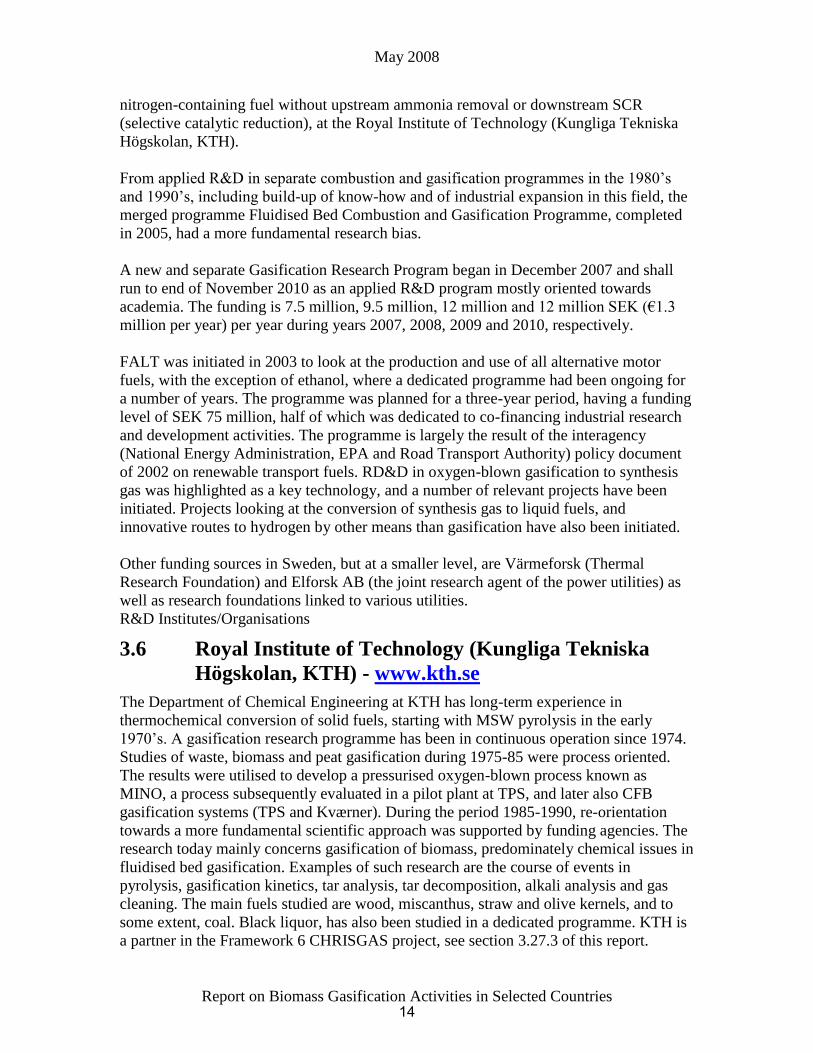
Experiments at KTH are primarily conducted in a pressurised bubbling fluidised bed
having a downstream filter and reformer or in an isothermal fluidised bed equipped with
two filters in series. In the CHRISGAS project, KTH perform experimental research in
the pressurised fluidised bed gasifier unit and in an atmospheric-pressure fluidised bed
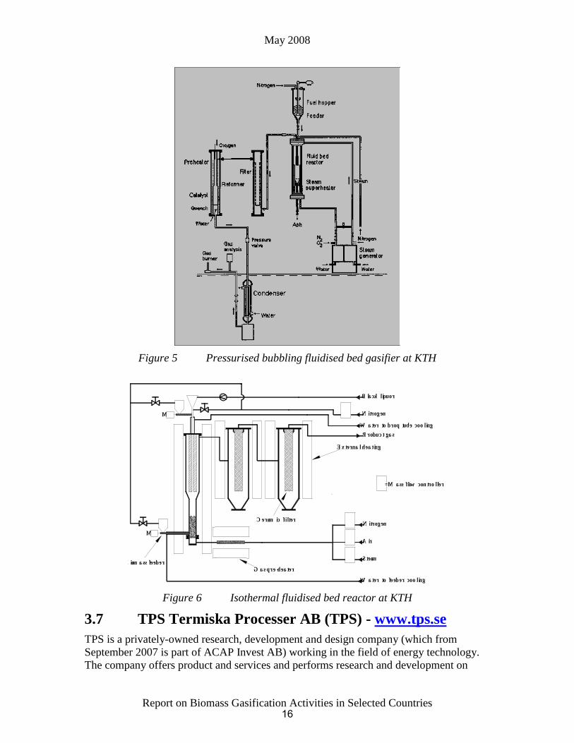
gasifier. The pressurised fluidised bed is depicted in Figure 5 and the small fluidised bed
reactor system is shown in Figure 6. In 2006, the first unit was complemented by a small
monolith tar cracking reactor. In 2007, a development for catalyst for tar cracking in SNG
applications was initiated.
15
May 2008
Report on Biomass Gasification Activities in Selected Countries
Figure 5 Pressurised bubbling fluidised bed gasifier at KTH
Ceramic fi lter
G as pre -heaterBiomass feeder
M
M
Water to feeder cooling
Nitrogen
Air
Steam
= M ass flow controller
Black liquor
Product gas
Nitrogen
External heating
Water to drop tube cooling
Figure 6 Isothermal fluidised bed reactor at KTH
3.7 TPS Termiska Processer AB (TPS) - www.tps.se
TPS is a privately-owned research, development and design company (which from
September 2007 is part of ACAP Invest AB) working in the field of energy technology.
The company offers product and services and performs research and development on
16
May 2008
Report on Biomass Gasification Activities in Selected Countries
gasification and combustion. Commercial exploitation of the new techniques developed
by the company normally progress through large-scale demonstration plants to
commercial operating plants. This type of exploitation has been achieved through
technology licensing and joint venture activities. Research and development projects of
TPS have often been funded by STEM, the EU and by private companies.
TPS was the designated technology supplier for the Grève-in-Chianti project in Italy, the
Brazilian BIG-GT project and the ARBRE project. TPS is also a partner in the
Framework 6 CHRISGAS project.
TPS’s R&D work on biomass gasification began in the late 1970’s. During the early
1980’s, the work concentrated on the development of the MINO process for gasification
of wood and peat to synthesis gas. This oxygen-blown process featured a high
temperature filter and a catalytic gas cleaning step. A pilot plant of 2.5 MW capacity was
operated at up to 28 bar. During the latter part of the 1980’s, research and pilot plant test
work concentrated on the air-blown atmospheric-pressure CFB gasification process,
featuring a patented gas cleaning step, and its application to the thermal processing of
biomass and waste fuels. TPS had a 2 MW atmospheric-pressure gasification pilot plant
on its premises, including a CFB gasifier, CFB tar cracker, filter, wet scrubber and diesel
engine, up until the company’s relocation in 2006.
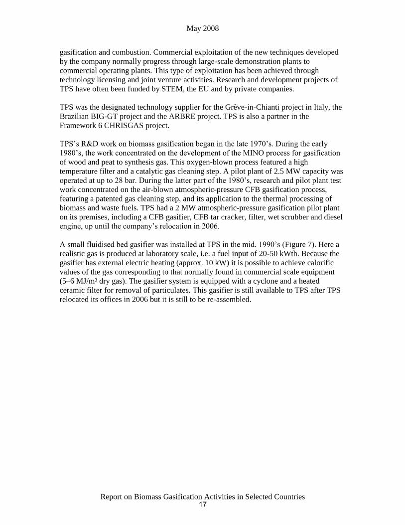
A small fluidised bed gasifier was installed at TPS in the mid. 1990’s (Figure 7). Here a
realistic gas is produced at laboratory scale, i.e. a fuel input of 20-50 kWth. Because the
gasifier has external electric heating (approx. 10 kW) it is possible to achieve calorific
values of the gas corresponding to that normally found in commercial scale equipment
(5–6 MJ/m³ dry gas). The gasifier system is equipped with a cyclone and a heated
ceramic filter for removal of particulates. This gasifier is still available to TPS after TPS
relocated its offices in 2006 but it is still to be re-assembled.
17

May 2008
Report on Biomass Gasification Activities in Selected Countries
Figure 7 The 20 kWth air-blown bubbling fluidised bed gasifier at TPS
A flexible pressurised apparatus, operating at up to 30 bar, was also designed and
installed at TPS in the mid 1990’s. The purpose of this apparatus was to perform high
temperature gas cleaning investigations by means of thermal, catalytic or chemical
procedures. A semi-continuous fuel feeding concept, at a maximum rate of 700 g/h,
allows constant formation of a gas product at 700ºC. The gas product, or gas from
another external source, e.g. gas bottles, is subsequently introduced into a fixed bed
secondary reactor where gas clean-up or reforming takes place. This apparatus is also still
available to TPS after TPS relocated its offices in 2006 but it is still to be re-assembled
3.8 Lund University (LTH) - www.lth.se
Gasification research started at the Department of Chemical Engineering II, LTH in 1975
with work focused on oil shale gasification. The research group worked in close co-
operation with Swedish mineral industries, and apart from TGA experiments, the
majority of the work was directed towards development, construction, and operation of a
laboratory-scale fluidised bed gasifier.
In 1978, pyrolysis and gasification experiments using biomass and other domestic fuels
as feedstock began. In 1981, a high-pressure TGA was built in which characterisation
studies on peat and biomass were carried out. Gasification studies using a conventional
fluidised bed gasifier were also performed. These activities were followed in 1985 by
biomass thermochemical conversion studies in a specially-designed high temperature
entrained phase reactor.
18

May 2008
Report on Biomass Gasification Activities in Selected Countries
In 1991, a government-supported evaluation of Swedish gasification research
recommended expansion of pressurised biomass gasification research at the Department
of Chemical Engineering II, and, as a result, a biomass PICFB (Pressurised Internal
Circulating Fluidised Bed) gasifier test rig was installed at the Chemical Center at LTH.
The idea was to have R&D support for the Värnamo biomass-fuelled IGCC plant, which
was then in the planning phase.
From the mid. 1990’s onwards, the project group was involved in several EC-sponsored
R&D projects where the PFB test rig played an important role in the experimental
investigations.
A new project at LTU “GreenSyngas” investigates advanced gas cleaning devices for
application to product gas from a biomass gasifier for upgrading to a syngas for
production of motor fuels. Ten partners are involved in the project, including Technical
University Munich and Delft University of Technology, and LTU is the Co-ordinator.
3.9 Växjö University (VXU) - www.vxu.se
The Municipality of Växjö has a declared ambition to become a fossil-free-community.
VXU is the second largest University in southern Sweden with more than 12 000
students. 75% of the 800 persons employed are researchers. The Division of Bioenergy,
consisting of two professors, eight graduate students and a post-doctorate position, has
research activities in the field of biomass combustion and projects where the scientific
activities are directed towards aerosol science in combustion aerosols, drying and
handling of biomass, and studies on the catalytic deactivation processes. At the School of
Industrial Engineering, the R&D programme “Wood Design and Technology” is directed
towards forestry, logistics, industrial production economy for forestry and marketing of
wood and wooden products.
VXU is the host research organisation for the Växjö Värnamo Biomass Gasification
Centre (VVBGC, www.vvbgc.com) and also the co-ordinator of the CHRISGAS project
and therefore it will be increasingly involved in gasification research in the coming years.
3.10 MittUniversitetet - www.miun.se
The School of Engineering at MittUniversitetet (Mid-Swedish University) in Härnösand
has recently become engaged in biomass gasification activities. This is supported by local
and regional organisations, which include forest industries, communities and a regional
environmental initiative, Biofuel Region North.
Based on funding from EU regional support grants, grants from FALT and from other
local sources, an thermal indirect type, sand circulating pilot gasifier of 150 kW thermal
capacity, for oxygen-free generation of synthesis gas was mechanically complete in 2007,
Figure 7, and is now in the commissioning phase in early 2007. The aim is to develop,
jointly with other regional stakeholders, a small-scale Fischer-Tropsch concept for local
use. Support is provided by KTH in the gasification area of the scientific work. After
starting the gasifier, plans are to integrate with a small FT unit.
19

May 2008
Report on Biomass Gasification Activities in Selected Countries
Figure 7 The MittUniveristet indirect gasifier
3.11 Umeå University (UmU) - www.umu.se
UmU is engaged in research in gasification and combustion, mainly specialising in the
inorganic chemistry of ash constituents and its impact on bed materials and
agglomeration, slagging and fouling properties. Through the Biofuel Region North,
Umeå University also collaborates with Mitthögskolan, and with the Energy Technology
Center on black liquor inorganic solids, see below.
3.12 Luleå Technical University (LTU) - www.luth.se
LTU is the parent organisation of ETC (see below), and collaborates with ETC on some
activities in black liquor gasification. Previously, a small-scale BIG-GT CHP concept
was developed, which included a cyclone gasifier to be used as a combined gasifier and
solid separator integrated with a combustor of a small, low inlet temperature gas turbine.
Both atmospheric and pressurised tests were made on this concept. However, although
the most recent project in the unit has been completed its development is on hold.
3.13 Energy Technology Center (ETC), Piteå -
www.etcpitea.se
ETC, a foundation based in Piteå, was formed in 1989. The activities at ETC were
boosted in 1993 when Assi Domän Kraftliner (presently Kappa Kraftliner) made their old
laboratory available to ETC. The laboratory was rebuilt, re-equipped and inaugurated in
1994, after which close collaboration was started with UmU and LTU. The research
activities focused on combustion and gasification of biofuels. ETC is the host
organisation of the 3.5 MW pressurised oxygen-blown black liquor gasification
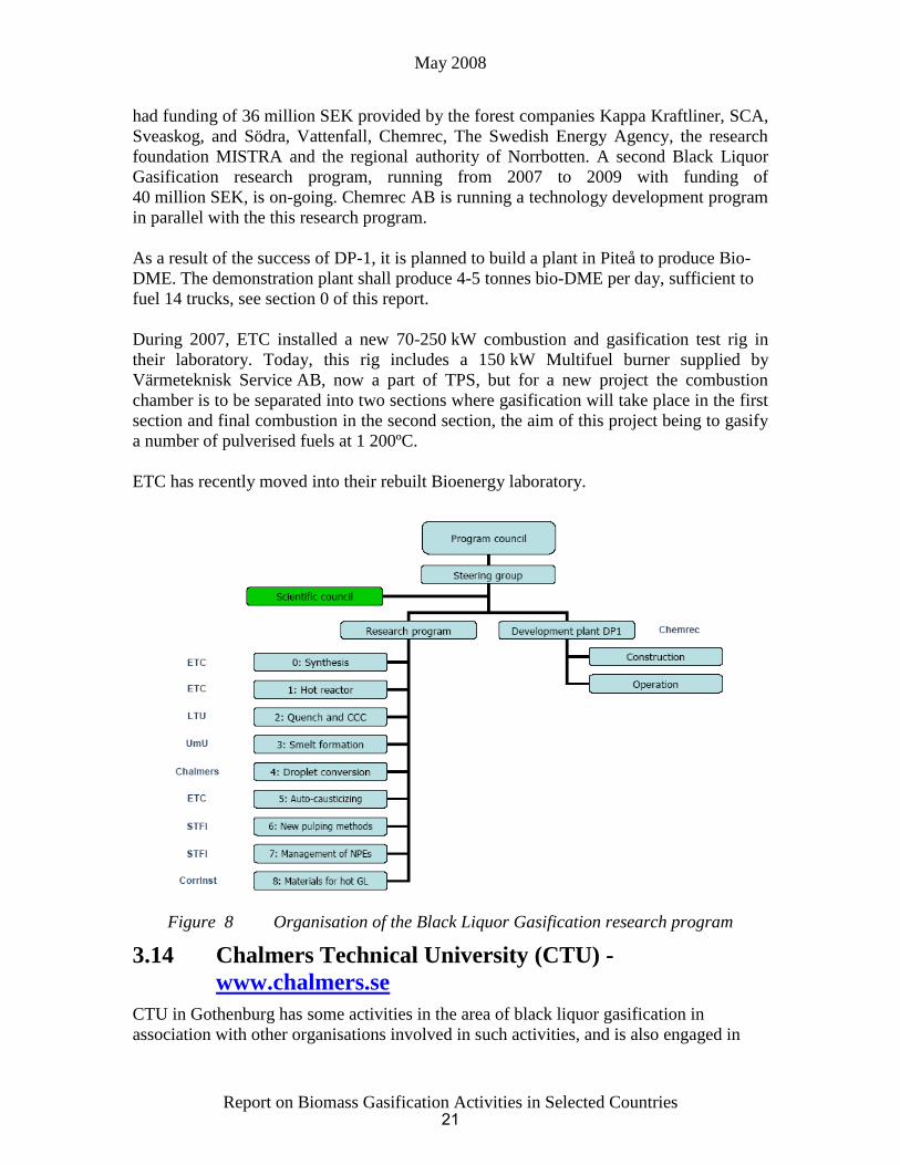
Development Plant 1 (DP-1). ETC was coordinator of the associated Black Liquor
Gasification research program (http://etcpitea.se/blg/) with projects at LTU, UmU,
Chalmers University of Technology, STFI-Packforsk (one of the world’s leading R&D
companies in the fields of pulp, paper, graphic media, packaging and logistics) and the
Swedish Corrosion Institute (Figure 8). The program period was from 2004 to 2006 and
20
May 2008
Report on Biomass Gasification Activities in Selected Countries
had funding of 36 million SEK provided by the forest companies Kappa Kraftliner, SCA,
Sveaskog, and Södra, Vattenfall, Chemrec, The Swedish Energy Agency, the research
foundation MISTRA and the regional authority of Norrbotten. A second Black Liquor
Gasification research program, running from 2007 to 2009 with funding of
40 million SEK, is on-going. Chemrec AB is running a technology development program
in parallel with the this research program.
As a result of the success of DP-1, it is planned to build a plant in Piteå to produce Bio-
DME. The demonstration plant shall produce 4-5 tonnes bio-DME per day, sufficient to
fuel 14 trucks, see section 0 of this report.
During 2007, ETC installed a new 70-250 kW combustion and gasification test rig in
their laboratory. Today, this rig includes a 150 kW Multifuel burner supplied by
Värmeteknisk Service AB, now a part of TPS, but for a new project the combustion
chamber is to be separated into two sections where gasification will take place in the first
section and final combustion in the second section, the aim of this project being to gasify
a number of pulverised fuels at 1 200ºC.
ETC has recently moved into their rebuilt Bioenergy laboratory.
Figure 8 Organisation of the Black Liquor Gasification research program
3.14 Chalmers Technical University (CTU) -
www.chalmers.se
CTU in Gothenburg has some activities in the area of black liquor gasification in
association with other organisations involved in such activities, and is also engaged in
21

May 2008
Report on Biomass Gasification Activities in Selected Countries
modelling of gasification energy cycles and catalysis research on the Fischer-Tropsch
process.
Chalmers has a long history and tradition in CFB combustion systems. More recently,
Göteborg Energi invested 11.5 million SEK in the construction of a nominal 2 MW (2-4
MW range) indirect gasifier supplied by Metso Power at CTH. The gasifier is connected
to the existing CFB co-generation boilers drawing hot sand from the combustor and
recycling char and cold sand, see Figures 9 and 10. Erection of the gasifier started in July
2007 and initial tests and the first measurement campaign were scheduled for November
2007 and February 2008, respectively. Approx 80 h operation with fuel and 250 h
without fuel have this far been logged, and tests have been performed on both wood chips
and wood pellets. Initial gas analysis data is given in the table below.
Gas analysis Vol% dry gas
H2 23
CH4 17
CO 41
CO2 15
C2H4 ~2,5
C2H6 0,5
N2 1
Tar Not analysed
LHV MJ/Nm3
The plant shall be used for development of the gasification technology for use in power
production and for producing motor fuels. The official inauguration of the plant will take
place at the end of April 2008.
22

May 2008
Report on Biomass Gasification Activities in Selected Countries
Figure 9 Integration of an indirect gasifier and a CFB boiler to be demonstrated at
2 MW scale
Figure 10 Integration of an indirect gasifier and a CFB boiler at Chalmers
3.15 Mälardalens Högskola - www.mdh.se
Mälardalens Högskola in Västerås has some limited activity on black liquor gasification
based on the fluidised bed process of ABB.
23

May 2008
Report on Biomass Gasification Activities in Selected Countries
3.16 Svenskt Gastekniskt Centrum (SGC) - www.sgc.se
SGC is the R&D centre for the natural gas industry in Sweden, an industry which is still
quite limited in comparison to continental Europe. Traditionally, SGC has not looked so
much at thermal gasification but has looked at biomass more as a source for biogas by
fermentation. However, with the emerging interest for SNG, GTC has increased its
profile if not its activities in the area of biomass gasification.
Industrial Biomass Gasification Activities, 1997-2006
3.17 General overview
Limited commercial development of biomass gasification in Sweden has taken place in
different markets during different periods. In the mid. 1970’s, and influenced by similar
development in the USA, a waste gasification plant (Motala Pyrogas) was built. After the
second oil crisis, a new process for methanol from biomass “MINO” was developed at
pilot scale but not commercialised.
To replace oil in existing kilns, e.g. lime kilns and dryers, fixed bed and circulating
fluidised bed gasifiers (CFBG) were installed. One plant for district heating was also
built. As a result of falling oil prices after 1986, no further gasifiers for these applications
were built.
During the 1990’s, future higher power prices were expected which led to the
development of gasifier/gas turbine combined-cycle (BIG-CC) both at pilot plant and
semi-commercial scale.
Figure11 and Table 3 give an overview of existing “commercial” gasifiers in Sweden.
Further details on these gasifiers are given below, as well as descriptions of other
technologies related to biomass gasification such as waste and black liquor gasification.
24

May 2008
Report on Biomass Gasification Activities in Selected Countries
Figure 11 Commercial biomass gasifiers in Sweden
Table 3 “Commercial” gasifiers in Sweden (1983-2006)
Process Location Type Size
(MWth)
Fuel Commissioned
date
Application Status
Bioneer Vilhelmina UD 5 sod peat 1986 boiler operating
Foster
Wheeler
Norrsundet CFB 20 bark/wood chips 1983 lime kiln shut down
in 2008
Foster
Wheeler
Karlsborg CFB 25 bark/wood chips 1985 lime kiln n.o.?
Metso
(Götaverken)
Värö CFB 35 bark/wood chips 1987 lime kiln operating
BIOFLOW Värnamo PCFB 18 wood chips 1994-96 IGCC See below
(test unit)
Chemrec
(Kværner)
(test unit)
Frövifors EF 4 black liquor 1993 boiler n.o.
Chemrec Piteå EF 1 black liquor 2005- pilot Operating
CHRISGAS Värnamo PCFB 18 biomass 2008 Synthesis
gas pilot
planned
DD = downdraft reactor, UD = updraft reactor, EF = entrained flow reactor, n.o. = not in operation
’OPEN TOP’ BIONEER BATTELLE/FERCO KVÆRNER HTW/LURGI
FLUIDYNE B&W VØLUND GÜSSING LURGI BIOFLOW/F-W
XYLOWATT NOVEL F-W CARBONA
PPC TPS
PYROFORCE
TERI
10 kW 100 kW 1000 kW 10 MW 100 MW FUEL CAPACITY
DOWNDRAFT FIXED BED UPDRAFT FIXED BED CFB
CFB or FB
BUBBLING FB Pressure > 1 MPa
Fuel
Air
Gas
Ash
25
May 2008
Report on Biomass Gasification Activities in Selected Countries
3.18 Downdraft gasifiers
See previous Country Report from 2006. Activity in this area has been low in recent
years.
3.19 Updraft gasifiers
Three updraft gasifiers have been installed in Sweden. The Finnish “Bioneer” gasifier
has, despite some problems, e.g., with feeding and varying gas quality, been running well
on both peat and wood chips. The feeder hopper design has been changed in one of the
plants. The most significant emission problem with fuels such as peat with a high
nitrogen content (250-350 mg/MJ) is NOx. After 1986 no units have been sold in Sweden
due to the low oil prices.
3.20 CFB gasifiers
The CFB lime kiln gasifiers sold in Sweden were ordered before 1986 when the oil price
was high and ash enrichment in the black liquor recovery cycle was a problem at the
pulverised wood combustion lime kiln at ASSI, Piteå, Sweden (Now Kappa Kraftliner).
At least two of the three plants, two from Foster Wheeler and one from Metso
(Götaverken) (Table 3), are still in continuous operation.
All the CFB gasifiers installed suffered from start-up and related problems. Gas leakages
and explosions in the feed hopper were major problems in the Norrsundet gasifier.
Sintering problems led to a special design of the lower part of the gasifier with easy
access to clean out sinters (Foster Wheeler). Multiple gas uses in lime kiln and boiler and
“hot dirty gas” valves have been a problem in the Metso (Götaverken) Värö gasifier.
Erosion in the valves led to a short valve lifetime. Expansion problems in the hot gas duct
were caused by settling of dust, which then required unforeseen insulation of the lower
part of the duct. Problems in the “hot gas” fired dryer were related to the high dust
content partly in the hot flue gas furnace and partly in the flue gas cleaning. The low
BTU gas combustion characteristics “longer and cooler flame” might, depending on the
original design of the rotary lime kiln, necessitate the need for oven and/or burner
modification. In 2003, this gasifier was operated with enriched air to de-bottleneck the
lime kiln in order to increase pulp capacity.
Despite some operational problems, the CFB gasifiers for lime kilns have been in
continuous operation for more than fifteen years and have accumulated more operating
hours than any other biomass gasifiers in the world.
3.21 Power generation with biomass gasification
Three main routes for power generation from biomass by using gasification have been
studied in Sweden:
atmospheric gasification coupled to dual fuel engine (3-10 MWe, TPS)
pressurised gasification with hot gas cleaning and IGCC. Either relatively small-scale
demonstration (6 MWe, Sydkraft/Foster Wheeler, see below) or large-scale (> 40
MWe, Vattenfall, see below)
26
May 2008
Report on Biomass Gasification Activities in Selected Countries
atmospheric gasification coupled to cold gas cleaning and IGCC at moderate size (10-
100 MWe, TPS, see below)
3.22 Waste gasification
Gasification of waste is an interesting option due to the potentially higher yield of
electricity, a more stable residue and cheaper gas cleaning as a result of the lower gas
volume to be treated.
In ordinary combustion plants, the yield of electricity is limited to approximately 23% by
high-temperature corrosion of the superheaters. Cleaning the gas before combustion
could increase the electricity yield in a steam cycle to 28%, and, if coupled to a gas
turbine, result in efficiencies of up to 35-40%. TPS has tested the gas cleaning at pilot
plant scale. The test indicated that despite a relatively high tar load in the gas due to the
fuel’s chlorine content, the bag house filters at about 200°C could be used to recover
dust, HCl and mercury. Two TPS CFB gasifiers, without fuel gas cleaning, but integrated
with a hot gas combustor and advanced flue gas cleaning, were built outside Florence,
Italy by Ansaldo Aerimpianti and put into operation (see below).
Mälarenergi AB, Sweden has plans to build a 200 MWth gasifier and fire the product
gasifier in an existing peat- and coal-fired boiler in Västerås. The feedstock shall be
number of different fuels but the primary fuel shall be sorted household and industrial
waste. The capital cost of this gasification alternative is less that of a new grate-fired
boiler and it will allow the possibility of a higher electrical efficiency. Mälarenergi
understands that the gasification concept is well proven but the necessary gas cleaning
has not yet been proven at large scale.
For hazardous waste, a special plasma-supported process “ScanArc” has been developed
(see section 3.27.6 of this report).
3.23 Black liquor gasification
Tomlinson boilers have been used and developed continuously for more than 100 years in
Kraft pulp chemical recovery processes. Their performance is very good in many ways,
but there are some limitations in the process, such as a fixed ratio between sulphide and
sodium in the melt. To increase the process flexibility and power output, new process
concepts such as black liquor gasification are considered. A future black liquor
gasification IGCC system could be combined with bark/chips gasification for a power
system with high yield of electricity in the pulp and paper industry.
Two different processes have been developed in Sweden. One is from former SKF
Plasma Technology and has been developed by Chemrec. The basic idea of the process is
to use an entrained flow gasifier at atmospheric pressure for boosting capacity in the soda
recovery cycle instead of installing a new large black liquor boiler. A first demonstration
plant (4 tonnes/hour dry substance) was erected at the Frövifors Mill in Sweden and was
started up in 1992-93 (see later). A pressurised test unit in Karlstad has been operated.
There were also plans to erect a new demonstration plant including a gas turbine at Assi,
Piteå. A grant for this demonstration plant was awarded by the Swedish State, but was
27

May 2008
Report on Biomass Gasification Activities in Selected Countries
staged to start with a research programme involving a smaller pilot facility commissioned
in 2005, and for which there is also paper and pulp industry co-financing. Further details
of this process development are given below.
ABB developed a low temperature CFB gasifier for black liquor in the late 80’s. Tests in
a small-scale fluidised bed gasifier showed that the carbon content could be reduced to an
acceptable level. The fluidised bed has also been shown to work well without any
additional fuel except for the black liquor organic. ABB also operated a pilot plant
gasifier in Västerås, Sweden, with a fluidised bed reactor both under atmospheric and
slightly pressurised conditions. This development is still worked on by Mälardalens
Högskola, Västerås.
3.24 Synthesis gas for liquid fuels and SNG
Following the oil crisis in the 1980’s, development on synthesis gas from biofuels and
peat was initiated, on the one hand by developments and co-operation with
Rheinbraun/UHDE on the HTW process and on the other hand by development of the
MINO process.
Since 2003, the interest in the field of synthesis gas has returned, and work has been
initiated both on black liquor and on biomass, see sections of this report on Chemrec and
CHRISGAS, both focusing on liquid motor fuels.
However, and somewhat more surprisingly, since the natural gas grid in Sweden only
covers the west coast from Malmö to the Norwegian border, an interest for SNG from
biomass emerged in 2005. Project Rya was a two year study co-ordinated by CTU,
financed by STEM and Göteborg Energi AB, and completed in 2006. The study was
aimed at evaluating the effects of introducing product gas from biomass gasification into
Gothenburg’s district heating network, in Western Sweden as a region and from a more
general and long-term system perspective. One focus of the study, in which Repotec
(www.repotec.at/en/) the supplier of the gasification plant in Güssing assisted, was the
integration of a 100 MW biomass gasification plant with the existing natural gas-fired
combined-cycle and district heating plant at Rya Kraftvärmeverk. Another focus was a
conceptual study of different technical process alternatives for production of heat,
electricity and motor fuels, including a more long-term alternative for hydrogen
production. Of the gasification-based alternatives studied, the most economic robust
solution was the production of SNG from wood chips for use as a motor fuel. Rebuilding
Rya Kraftvärmeverk for partly biomass-based heat production based on gasification was
also of economic interest but a rebuild for electric production with higher electric
efficiency was of more interest.
Göteborg Energi has an ambitious project called GoBiGas that has the aim of
demonstrating the possibilities of the gasification technology on a commercial scale (i.e.
approx. 100 MW SNG) by placing a gasification unit in operation by 2012. It is said that
by fulfilling this aim Göteborg Energi AB will take a significant step towards their
long-term target of replacing the natural gas in their plants and meeting their customers’
demand for renewable gas. In February 2007, the board of Göteborg Energi decided to
28

May 2008
Report on Biomass Gasification Activities in Selected Countries
support the project to at least the decision on preliminary investment is taken in the
summer of 2008.
E.ON Sweden has completed a preliminary study on the technical and economical
conditions for producing electricity/heat in a gas turbine and/or produce SNG as a
complement to natural gas. The results of the study are still being evaluated and a
decision to go ahead with the design of a 50 MWth gasification demonstration plant is
pending.
Technology Implementation and Plant and Projects
3.25 Commercial plants before 1990 (not in operation
today)
See previous reports for details of these older plants.
3.26 Commercial plants in operation after 1990 or still in
operation
In total, three commercial plants based on atmospheric CFB-gasification with a lime kiln
have been erected in Sweden, with the pulp industry as gas customer. At least two of
these gasifiers are still in operation today, for the third one at Karlsborg the operating
status appears to have changed recently and the extent of operation is not known. Foster
Wheeler erected the first unit, proving in practice that by drying the fuel, “flash
pyrolysis” and pre-heated air, a rich enough gas could be produced to achieve the desired
high temperature in the lime kiln. Other Swedish companies developed similar gasifiers
for the same application, e.g. Fläkt/TPS and Kværner. The technical description below
concentrates on the Kværner technology and the plant in Värö. The TPS technology is
described elsewhere in this report.
3.26.1 The Värö plant
The Värö gasifier plant was delivered by Götaverken (today, part of the Metso group)
and commissioned in 1987. The plant includes a rotary drum dryer, fuelled by biogas,
and fuel pre-treatment (Figure 12). Crushing of the fuel, both bark and wood wastes,
takes place in a primary and a secondary hammer mill to achieve the fuel size necessary
for the gasifier. The feed system consists of two pressurised rotary feeders with cooled
transport screws to the gasifier.
29

May 2008
Report on Biomass Gasification Activities in Selected Countries
Figure 12 Biomass gasification plant at Värö Mill
The gasifier was developed based on Götaverken’s CFB combustion experience and
gasification experience from KTH. A 2 MW pilot test unit preceded the erection of the
Värö plant. The Värö gasifier is a CFB of 30 MW fuel capacity with the fuel feed placed
a few metres above the bottom of the bed to create two distinct reaction zones. In an
upper zone, the fuel reacts via flash pyrolysis in the hot bed/inert flue gas atmosphere to a
gas rich in C2:s and also tar.
The lower reaction zone is essentially for char combustion (recycled char) and, to some
extent, char gasification. In theory, char combustion/flash pyrolysis should be balanced if
the fuel has a small particle size. In practice, and with coarser particles, the zones will be
less well defined and separated. To limit the amount of heavy hydrocarbons in the gas
and to allow for carryover of bed material to the lime kiln, dolomite is used as gasifier
bed material.
The gasifier is a refractory-lined free-standing vessel with solids recycling (Figure 13)
and air/gas heat exchange. The product gas is piped to the dryer furnace and the lime kiln,
controlled by valves.
30

May 2008
Report on Biomass Gasification Activities in Selected Countries
Figure 13 Värö gasifier
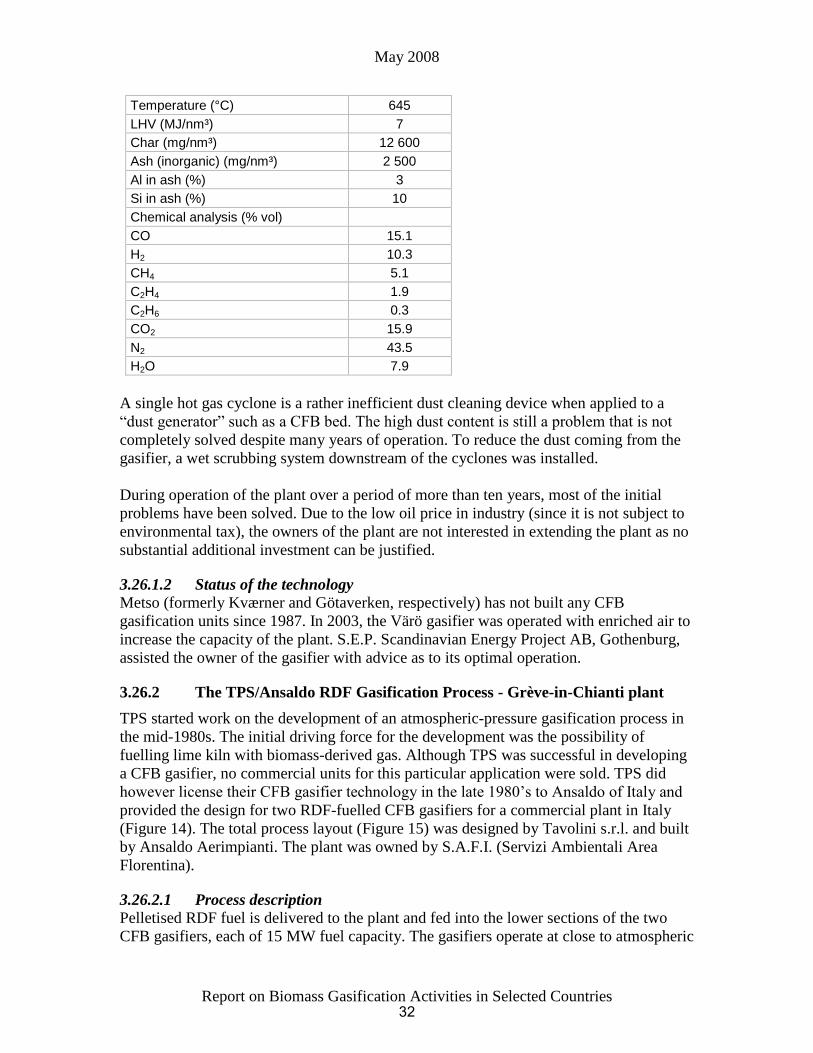
3.26.1.1 Operational experience
Normally, the product gas quality (HHV) is better than design figures (Table 4).
Due to a conservative design of the heat exchangers and pipes (i.e. low velocities), a
tendency for char/tar adhesion to the surfaces and settling of dust in the lower region of
the horizontal pipes occurred. This led to mechanical problems when restarting the unit
(i.e. differential expansion). After a few years, a smaller transport pipe was installed
which mainly solved the problem. Severe erosion/corrosion of high temperature control
valves occurred and led to a reduction of the number of delivery points for the gas from
three to two. Stopping the fuel feed and burning off the deposits every week or second
week cleaned the heat exchangers sufficiently.
Table 4 Physical and chemical data from the Värö gasifier
31
May 2008
Report on Biomass Gasification Activities in Selected Countries
Temperature (°C) 645
LHV (MJ/nm³) 7
Char (mg/nm³) 12 600
Ash (inorganic) (mg/nm³) 2 500
Al in ash (%) 3
Si in ash (%) 10
Chemical analysis (% vol)
CO 15.1
H2 10.3
CH4 5.1
C2H4 1.9
C2H6 0.3
CO2 15.9
N2 43.5
H2O 7.9
A single hot gas cyclone is a rather inefficient dust cleaning device when applied to a
“dust generator” such as a CFB bed. The high dust content is still a problem that is not
completely solved despite many years of operation. To reduce the dust coming from the
gasifier, a wet scrubbing system downstream of the cyclones was installed.
During operation of the plant over a period of more than ten years, most of the initial
problems have been solved. Due to the low oil price in industry (since it is not subject to
environmental tax), the owners of the plant are not interested in extending the plant as no
substantial additional investment can be justified.
3.26.1.2 Status of the technology
Metso (formerly Kværner and Götaverken, respectively) has not built any CFB
gasification units since 1987. In 2003, the Värö gasifier was operated with enriched air to
increase the capacity of the plant. S.E.P. Scandinavian Energy Project AB, Gothenburg,
assisted the owner of the gasifier with advice as to its optimal operation.
3.26.2 The TPS/Ansaldo RDF Gasification Process - Grève-in-Chianti plant
TPS started work on the development of an atmospheric-pressure gasification process in
the mid-1980s. The initial driving force for the development was the possibility of
fuelling lime kiln with biomass-derived gas. Although TPS was successful in developing
a CFB gasifier, no commercial units for this particular application were sold. TPS did
however license their CFB gasifier technology in the late 1980’s to Ansaldo of Italy and
provided the design for two RDF-fuelled CFB gasifiers for a commercial plant in Italy
(Figure 14). The total process layout (Figure 15) was designed by Tavolini s.r.l. and built
by Ansaldo Aerimpianti. The plant was owned by S.A.F.I. (Servizi Ambientali Area
Florentina).
3.26.2.1 Process description
Pelletised RDF fuel is delivered to the plant and fed into the lower sections of the two
CFB gasifiers, each of 15 MW fuel capacity. The gasifiers operate at close to atmospheric
32

May 2008
Report on Biomass Gasification Activities in Selected Countries
pressure and at a temperature of approximately 850°C, employing air as the
gasification/fluidising agent. Part of the air is injected into the gasifier vessel through the
bottom section, the remainder being injected part way up the vessel. This pattern of air
distribution creates a high-density bed in the lower part of the vessel, which allows the
gasifier to handle relatively large-sized fuel particles. The maximum length of the RDF
pellets delivered to the plant is 150 mm TPS has stated that its gasifier can operate on
unpelletised RDF fluff and that from the gasification point of view there is no need to
pelletise the fuel.
Figure 14 TPS/Ansaldo RDF gasification plant in Grève, Italy
CEMEN T IND U STRY
(MU LTI-U SE)
PRO CESS GA S
PO WER
PRO D UCTION
SECTION
G ASIFICATIO N
SECTION
FLU E GA S
TREATMENT SECTION
ELECTRIC PO WER
(p u b lic u se)
A SH ES
H EA T RECO VERY
FU EL
Figure 15 Process scheme of TPS/Ansaldo RDF gasification plant in Grève-in-
Chianti
33

May 2008
Report on Biomass Gasification Activities in Selected Countries
The raw gas from each gasifier passes through two stages of solids separation before
being fed to a furnace/boiler. Alternatively, part of this raw gas stream can be led to a
nearby cement factory to be used as fuel in the cement kilns. The gas heating value is
high, averaging 8 MJ/Nm³. The flue gas exiting the boiler is cleaned in a Research-
Cottrell three-stage dry scrubber system before being exhausted through the stack. Steam
produced in the boiler drives a 6.7 MWe steam condensing turbine. Due to local
restrictions, no flaring of the gas is permitted.
3.26.2.2 Status
Pilot tests at 2 MW thermal fuel capacity on RDF pellets were carried out at TPS during
1989-90. The Grève plant was turned over to the customer in 1993. Operational problems
in the Grève plant were mainly related to combustion of the gas with high dust content.
At times, fuel supply to the plant was limiting for the operation of the plant until an RDF
pellet production factory was commissioned in 1996.
The original process layout of the plant included a dedicated furnace/boiler and flue gas
cleaning system for each of the two gasifiers. To date, only one such line has been
installed.
In 1998, it was planned to modify the plant to include a second combustion line and a
product gas cleaning system comprised of a new cyclone solids separator, a high-
temperature acid gas/dechlorination unit, a second cyclone solids separator, and a gas
cooler and ceramic filters. The cost of the modification was estimated at € 9.7 million, of
which € 1.5 million was provided through the EU THERMIE programme, but this project
was not realised by the partnership.
In the Italian section of the 2004 IEA Task 33 Country Report, it is reported that 4 000
and 5 000 tonnes of RDF were processed in 2000 and 2001, respectively. It appears that
the plant was finally closed in 2004, the reason given being that a modern large scale
waste-to-energy plant had been built in the region.
3.27 Development activities
3.27.1 The VEGA project
In 1990-91, Vattenfall AB and Tampella Power Inc. (today Metso) made a joint effort
through EnviroPower to develop a biomass-fuelled IGCC system. This system is based
on a simplified IGCC process employing the gasification technology originally developed
by the Institute of Gas Technology (IGT) in Chicago (today, the Gas Technology Institute
(GTI)), and an advanced hot gas clean-up system. Enviropower’s gasification pilot plant
of 15 MW thermal input (80 tonne per day on biomass) in Tampere, Finland was used for
research, development and component testing of the gasification and gas clean-up
process. Gas turbine combustion tests, using low BTU gas, were carried out at the
General Electric Power Generation Development Laboratory in Schenectady, USA.
Biomass fuel drying tests were performed at commercial facilities of different dryer
manufacturers. A novel fuel feeding system was developed and tested by Vattenfall for
the direct feeding of mainly biomass type fuels to pressurised systems.
34
May 2008
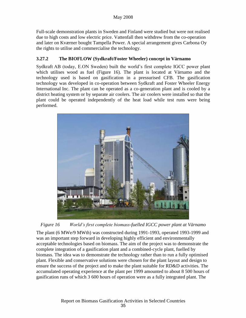
Report on Biomass Gasification Activities in Selected Countries
Full-scale demonstration plants in Sweden and Finland were studied but were not realised
due to high costs and low electric price. Vattenfall then withdrew from the co-operation
and later on Kværner bought Tampella Power. A special arrangement gives Carbona Oy
the rights to utilise and commercialise the technology.
3.27.2 The BIOFLOW (Sydkraft/Foster Wheeler) concept in Värnamo
Sydkraft AB (today, E.ON Sweden) built the world’s first complete IGCC power plant
which utilises wood as fuel (Figure 16). The plant is located at Värnamo and the
technology used is based on gasification in a pressurised CFB. The gasification
technology was developed in co-operation between Sydkraft and Foster Wheeler Energy
International Inc. The plant can be operated as a co-generation plant and is cooled by a
district heating system or by separate air coolers. The air coolers were installed so that the
plant could be operated independently of the heat load while test runs were being
performed.
Figure 16 World’s first complete biomass-fuelled IGCC power plant at Värnamo
The plant (6 MWe/9 MWth) was constructed during 1991-1993, operated 1993-1999 and
was an important step forward in developing highly efficient and environmentally
acceptable technologies based on biomass. The aim of the project was to demonstrate the
complete integration of a gasification plant and a combined-cycle plant, fuelled by
biomass. The idea was to demonstrate the technology rather than to run a fully optimised
plant. Flexible and conservative solutions were chosen for the plant layout and design to
ensure the success of the project and to make the plant suitable for RD&D activities. The
accumulated operating experience at the plant per 1999 amounted to about 8 500 hours of
gasification runs of which 3 600 hours of operation were as a fully integrated plant. The
35

May 2008
Report on Biomass Gasification Activities in Selected Countries
test runs were successful and the plant was operated on different wood fuels as well as
straw and refuse-derived fuel (RDF).
The demonstration programme was concluded in 2000 and the plant was mothballed as it
was not economical to operate given the commercial conditions prevailing in Sweden.
However, significant efforts have been made to make use of this plant as a research
facility and for this purpose a new company Växjö Värnamo Biomass Gasification Centre
(VVBGC) was established, see below.
A detailed summary report of the demonstration programme has been published in
Swedish and English: Krister Ståhl, Värnamoverket - Demonstrationsprogrammet 1996-
2000 (The Värnamo Plant, The Demonstration Program 1996-2000) Sydkraft Miljö och
Utveckling, 205 09 Malmö, www.eon.se.
3.27.2.1 Process description
A simplified process diagram, showing the components of the gasification plant, are
shown in Figure 17 and Figure 18, and some data given in Table 5.
Figure 17 Process diagram of Värnamo plant
36

May 2008
Report on Biomass Gasification Activities in Selected Countries
Figure 18 Cross section of the Värnamo gasification plant
Table 5 Technical data of the Värnamo plant
Power/heat generation 6 MWe/9 MWth
Fuel input 18 MW fuel (85% dry substance)
Fuel Wood chips (Several other fuels have been tested with good results.)
Net electrical efficiency (LCV basis) 32%
Total net efficiency (LCV basis) 83%
Gasification pressure/temperature 18 bar.g/950ºC
Lower calorific value of product gas 5 MJ/m³n
Steam pressure/temperature 40 bar.a/455ºC
Plant owner Sydkraft AB
The dried and crushed wood fuel is pressurised in a lock hopper system to a level
determined by the pressure ratio of the gas turbine, and fed by screw feeders into the
gasifier a few metres above the bottom. The operating temperature of the gasifier is
950-1 000°C and the pressure is approximately 18 bar.g.
The gasifier is an air-blown CFB and consists of the gasifier itself, cyclone and cyclone
return leg, all of which are fully refractory-lined. About 10% of the air in the gas turbine
compressor is extracted, further compressed in a booster compressor, and then injected
into the bottom of the gasifier. The fuel is dried, pyrolysed and gasified on entering the
gasifier. The gas produced transports the bed material and the remaining char to the top
of the gasifier and into the cyclone. In the cyclone, most of the solids are separated from
37

May 2008
Report on Biomass Gasification Activities in Selected Countries
the gas and are returned to the bottom of the gasifier through the return leg. The
recirculated solids contain some char, which is burned in the bottom zone where air is
introduced into the gasifier. Combustion of the fuel and gas maintains the required
temperature in the gasifier.
Downstream of the cyclone, the gas produced flows to a gas cooler and a hot gas filter.
The gas cooler is of a fire tube design and cools the gas to 350-400°C, after which the gas
enters the candle filter vessel where particulate clean-up occurs. Ash is discharged from
the candle filter, as well as from the bottom of the gasifier, and is cooled and
depressurised.
The gas produced is burned in the combustion chambers and expands through the gas
turbine, generating 4.2 MW of electricity. The gas turbine is a single-shaft industrial unit.
The fuel supply system, fuel injectors and the combustors were redesigned to suit the low
calorific value gas (5 MJ/m³).
The hot flue gas from the gas turbine is fed to the heat recovery steam generator, where
the steam generated, along with steam from the gas cooler, is superheated and then
supplied to a steam turbine (40 bar, 455°C), generating 1.8 MWe.
The plant is equipped with a flare on the roof of the gasification building, which is used
during start-up and to protect the gas turbine when testing under less well understood
conditions.
An extensive demonstration/development programme was carried out during 1996-2000.
The work was partly performed in collaboration between Sydkraft, Foster Wheeler,
Electricité de France and Elkraft. The overall aim of the programme was to verify the
status and future potential of the biomass IGCC concept from both technical and
economical points of view. In order to achieve this, it was important to identify and
verify the status of different parameters e.g. operability, maintainability and availability.
Of particular interest to the success of the gasification technology was verification of the
quality of the gas produced in the gasifier, as well as operation of the gas turbine.
3.27.2.2 Experience gained during test operation
The first gas was generated at low pressure in June 1993.
Tests with different bed materials, temperatures and pressure levels caused deposits to
occur at times. During the tests with limestone and dolomite as bed material,
recarbonisation of the limestone/dolomite resulted in deposits in the gas cooling system
which in turn provided insufficient cracking of high molecular by-products, which caused
fouling on the cooler tubes. The use of magnesite (MgO) as bed material in the gasifier
proved to be very successful. As magnesite is more expensive than dolomite, tests were
carried out to check the feasibility of recycling bottom ash, and thus reusing the
magnesite drained from the system. These tests proved to be successful. Whilst it was
concluded that significant deposits can be handled with a suitable design of gasifier and
downstream components, it is still believed that it will be useful to continue testing
38
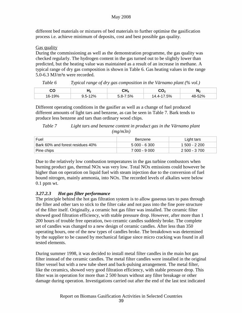
May 2008
Report on Biomass Gasification Activities in Selected Countries
different bed materials or mixtures of bed materials to further optimise the gasification
process i.e. achieve minimum of deposits, cost and best possible gas quality.
Gas quality
During the commissioning as well as the demonstration programme, the gas quality was
checked regularly. The hydrogen content in the gas turned out to be slightly lower than
predicted, but the heating value was maintained as a result of an increase in methane. A
typical range of dry gas composition is shown in Table 6. Gas heating values in the range
5.0-6.3 MJ/m³n were recorded.
Table 6 Typical range of dry gas composition in the Värnamo plant (% vol.)
CO H2 CH4 CO2 N2
16-19% 9.5-12% 5.8-7.5% 14.4-17.5% 48-52%
Different operating conditions in the gasifier as well as a change of fuel produced
different amounts of light tars and benzene, as can be seen in Table 7. Bark tends to
produce less benzene and tars than ordinary wood chips.
Table 7 Light tars and benzene content in product gas in the Värnamo plant
(mg/m3n)
Fuel Benzene Light tars
Bark 60% and forest residues 40% 5 000 - 6 300 1 500 - 2 200
Pine chips 7 000 - 9 000 2 500 - 3 700
Due to the relatively low combustion temperatures in the gas turbine combustors when
burning product gas, thermal NOx was very low. Total NOx emissions could however be
higher than on operation on liquid fuel with steam injection due to the conversion of fuel
bound nitrogen, mainly ammonia, into NOx. The recorded levels of alkalies were below
0.1 ppm wt.
3.27.2.3 Hot gas filter performance
The principle behind the hot gas filtration system is to allow gaseous tars to pass through
the filter and other tars to stick to the filter cake and not pass into the fine pore structure
of the filter itself. Originally, a ceramic hot gas filter was installed. The ceramic filter
showed good filtration efficiency, with stable pressure drop. However, after more than 1
200 hours of trouble free operation, two ceramic candles suddenly broke. The complete
set of candles was changed to a new design of ceramic candles. After less than 350
operating hours, one of the new types of candles broke. The breakdown was determined
by the supplier to be caused by mechanical fatigue since micro cracking was found in all
tested elements.
During summer 1998, it was decided to install metal filter candles in the main hot gas
filter instead of the ceramic candles. The metal filter candles were installed in the original
filter vessel but with a new tube sheet and back-pulsing arrangement. The metal filter,
like the ceramics, showed very good filtration efficiency, with stable pressure drop. This
filter was in operation for more than 2 500 hours without any filter breakage or other
damage during operation. Investigations carried out after the end of the last test indicated
39

May 2008
Report on Biomass Gasification Activities in Selected Countries
that there was no degradation of these elements although they had been exposed to gas
and ash not only from wood chips but also from RDF and straw.
3.27.2.4 Gas turbine experience
The gas turbine installed in the plant is a near-standard Typhoon from ABB Alstom Gas
Turbines in Lincoln, England (now Siemens Industrial Turbines). Modified components
are the combustors, the burners and the addition of an air bleed from the compressor. A
special design gas control module was also developed to control the product gas, steam
and nitrogen to the unit.
Prior to being supplied to Värnamo, the special combustors and burners were tested in a
rig in England utilizing synthetic gas. Combustion was always reliable in the turbine
whether operating on gas fuel or liquid. The relatively low heating value of the gas (about
1/10th of natural gas) caused no problem for the gas turbine and a stable flame was
always maintained even when the heating value was lower than normal. Not even during
earlier operation was it necessary to maintain a pilot flame of liquid fuel and operation
during all 3 600 hours as a fully integrated plant was on 100% gas for the LCV gas
operating range, i.e. from 40% to full load.
Complete combustion of the hydrocarbons was always achieved with emissions between
1 and 4 ppm only, whereas a slightly high figure of CO was observed with figures up to
and sometimes even above 200 ppm on part load.
As mentioned before, levels of NOx around 150 ppm were recorded when operating on
gas produced from biomass with high nitrogen content (such as bark), whilst the lower
nitrogen content of hardwood considerably reduces the NOx, down to as little as 50 ppm.
During commissioning and the first years of testing, forest residue and wood chips were
the fuels generally used. However, a variety of fuels were tested in the plant during the
demonstration programme, such as wood chips, forest residue (bark, branches, etc.),
sawdust and bark pellets, willow (salix), straw and RDF.
All these fuels proved to be easy to gasify without causing deposits or sinters in the
systems. Bark proved to be an excellent fuel, even with feed rates up to 100%, and was
easily gasified with the gas being suitable for filtration and gas turbine operation. The
high levels of alkalines in willow (salix) did not cause any problems in any part of the
system and the amount of sintered/agglomerated material in the bottom ash was very
small.
Straw has always been considered a very difficult fuel to burn/gasify due to its high
levels of alkaline and large amount of ash in the fuel. Also, the chlorine level is very high
in comparison to wood fuels. Tests were carried out with straw mixed with bark, and with
100% straw. About 200 tonnes of straw were gasified without any problems or sintering,
and a gas was produced with a hydrogen content slightly higher than normal, which
proved to be excellent for gas turbine operation.
40

May 2008
Report on Biomass Gasification Activities in Selected Countries
Encouraging results were achieved in the tests on RDF, including gas turbine operation
on the gas produced.
3.27.2.5 Conclusions from the demonstration programme
The difficulties encountered initially in the Värnamo project were overcome after a
couple of years of intense commissioning and testing.
The Demonstration Programme, which began in 1996, was very successful and proved
that pressurised biomass IGCC technology works. The complete plant was in operation in
excess of 3 600 hours with the gas turbine operating solely on product gas produced by
the gasifier. Huge experience was gained from more than 8 500 hours gasifier operation.
Results achieved are summarised as:
High pressure gasification technology works
Gas produced can be burnt in a gas turbine under stable conditions
Hot gas filtration is efficient and reliable
Technology is capable of gasifying “difficult fuels”
No harmful effects identified on gas turbine or other components
NOx emission slightly high at present for some fuels, but solutions available
Emissions of HC very low and emissions of dioxins below detection level also for
chlorine-rich fuels
The biomass gasification technology is very suitable for retrofit to existing natural gas
fired combined-cycle (NGCC) plants
The market potential for the pressurised gasification technology developed at Värnamo
can be summarised as follows:
Industrial back-pressure CHP generation plants, such as for process steam in the pulp
and paper industry, will have the highest competitiveness
The high fuel flexibility shown opens the way for building plants for more difficult
fuels, such as straw, RDF and bagasse
An interesting application may be to supplement a NGCC plant with a gasification
plant, so that part of the natural gas flow can be replaced by product gas
The competitiveness compared to conventional biofuel-fired condensing power plants
is promising
In the short-term perspective, the market will be dependent on political measures for
reducing CO2 emissions
Since 2000, efforts to create new partnerships to maintain and utilise the Värnamo plant
were made. In 2003, applications were made by several consortia to the EC for financial
support for projects aimed at generating a hydrogen-rich gas that can be upgraded to
commercial quality hydrogen or a synthesis gas, or for producing methanol, hydrogen,
ammonia and DME (Di Methyl Ether) or Fischer-Tropsch diesel from renewable fuels.
One application that was successful concerned a project based on the use of the Värnamo
plant, i.e. the CHRISGAS project, see next.
41

May 2008
Report on Biomass Gasification Activities in Selected Countries
3.27.3 The CHRISGAS project - www.chrisgas.com
Gasifying biomass to produce a hydrogen-rich synthesis gas and cleaning the gas by
steam reforming and upgrading promises higher efficiencies in the production of
hydrogen or liquid fuel for transport purposes. The achievable yield of motor fuel from
cellulosic biomass is higher for fuels derived via the gasification/synthesis gas route than
via the hydrolysis/ fermentation route.
3.27.3.1 Background
An application to DG Research in 2003 for part funding of the CHRISGAS project was
successful. This project is aimed at establishing the necessary design basis for each
process step and includes test work in the Värnamo plant using it for oxygen-blown
gasification to generate synthesis gas from biomass. The project started on 1st September
2004 and will continue through to 2009.
In order to guarantee the availability of the Värnamo plant by public funding when it was
mothballed by Sydkraft, a non-profit project-based company was established at Värnamo
by Växjö Energi AB and Värnamo Energi AB, both local publicly-owned energy
companies, on behalf of Växjö University. This company, named Växjö Värnamo
Biomass Gasification Centre (VVBGC) was incorporated in December 2003. The plant
and associated IPR were taken over from the previous plant owner in 2004, thereby
safeguarding access to and availability of the plant, including the use of qualified staff for
projects interested to use the Värnamo plant.
3.27.3.2 CHRISGAS objectives and structure
The primary objective of the CHRISGAS project is to demonstrate, in the Värnamo plant,
the manufacture of a hydrogen-rich gas from a renewable feedstock, i.e. biomass. The
demonstration part of the project consists of a number of tasks for which the objectives
are:
Conversion of several solid biofuels into a medium calorific value gas by gasification
at elevated pressure using a steam and oxygen mixture
Cleaning of the generated gas from particulates in a high temperature filter. Note that
hot gas cleaning is advantageous for the overall energy balance when a reformer is
applied directly after the cleaning section because reforming requires a high inlet
temperature
Purification of the generated gas by catalytic autothermal steam reforming of not only
tars, but of methane and other light hydrocarbons, to generate a raw synthesis gas
consisting mainly of carbon monoxide and hydrogen as energy carriers
In order to provide a sound technical background to the process to be installed at
Värnamo, a supporting R&D programme on various technical aspects of the proposed
process will be conducted, the objectives of which include:
Studies of the conditioning of the hydrogen-rich raw synthesis gas to the quality
stipulated for synthesis gas suitable for manufacture of DME or other potential
products
Studies of the production of these fuels from various biofuels, at the scale and cost
representative of typical biomass fuel chains in various regions in Europe
42

May 2008
Report on Biomass Gasification Activities in Selected Countries
Development of a feed system based on a piston feeder. The advantages of piston
feeding are that the total energy consumption is much lower than that of lock hoppers,
the feeder is more compact and the capacity of one feeder can be very large
During 2005 and 2006, planning of the modification of the plant for the CHRISGAS
project was made, and an application to STEM for the balance of funding required for the
program was submitted. In September 2006, following the application for financial
support in May 2006, an international expert evaluation of the project was made. STEM
evaluated this application favourably, but as a result budgetary restrictions and of the
STEM policy changes, 75% of the funding was allocated but only conditional on the
establishment of an industrial stakeholder group being formed to give stronger industrial
thrust to the project and to provide the balance of financing. The discussions regarding
industrial participation in the project have been on-going for a considerable time, and
have led to delays in the rebuilding of the plant.
The construction time estimated is approx. two years, so that in late 2009 at the earliest,
test work in the CHRISGAS project would begin. An addition of downstream units to
utilise the synthesis gas produced for production of liquid fuels, fuel cells, etc. is also
planned but is not part of CHRISGAS. Figure 19 gives some additional details of the
partners, the financing, etc. of the CHRISGAS project.
Sweden: Växjö University (co-ordinator), Växjö Värnamo
Biomass Gasification Centre (VVBGC), AGA-Linde, Catator,
KS Ducente, Royal Institute of Technology (KTH), S.E.P.
Scandinavian Energy Project, TPS Termiska Processer,
(Valutec),Växjö Energi
Denmark: TK Energi, Finland: Valutec, Germany: FZ Jülich,
Linde, Pall Schumacher, Italy: University of Bologna,
Netherlands: Technical University Delft, Spain: CIEMAT
•Budget 15.6 MEURO + costs outside project
• 9.5 M€ EU grant
• 1.5 M€ STEM grant + 7 M€ grant outside project
• Balancing financing 28 M€ applied for from STEM in May
Figure 19 CHRISGAS Partners and financing
3.27.3.3 Activities in the plant prior to the rebuild
The plant was mothballed in 2000. The first actions taken in 2004, apart from building a
new site organisation, was to make a status review of the existing facilities. This review
concluded that although, in general, the active mothballing scheme had prevented the
plant from any extensive deterioration, some localised damage had occurred from e.g.
freezing or corrosion, and furthermore, all wear in the plant on valves, etc. up to its
shut-down in 1999, naturally enough, remained and instrumentation had suffered from
aging. During the end of 2005 and the first half of 2006, all the mechanical repairs were
made, the vessel and other parts inspected and the turbines serviced.
43
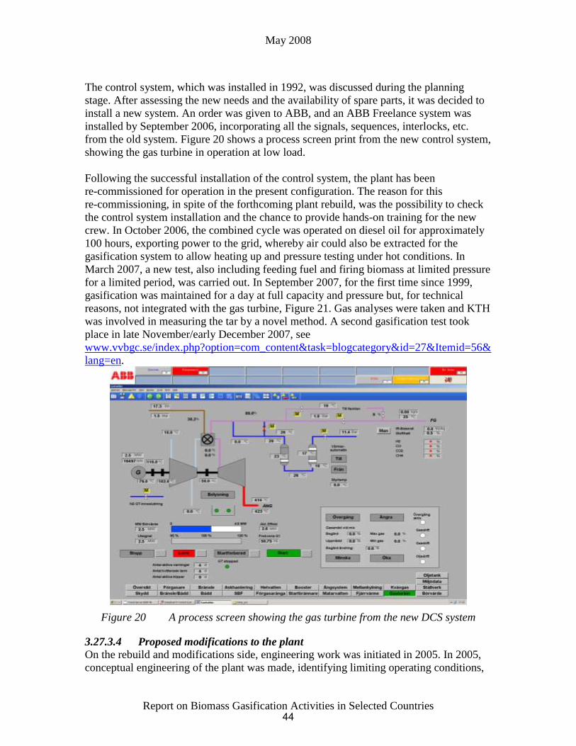
May 2008
Report on Biomass Gasification Activities in Selected Countries
The control system, which was installed in 1992, was discussed during the planning
stage. After assessing the new needs and the availability of spare parts, it was decided to
install a new system. An order was given to ABB, and an ABB Freelance system was
installed by September 2006, incorporating all the signals, sequences, interlocks, etc.
from the old system. Figure 20 shows a process screen print from the new control system,
showing the gas turbine in operation at low load.
Following the successful installation of the control system, the plant has been
re-commissioned for operation in the present configuration. The reason for this
re-commissioning, in spite of the forthcoming plant rebuild, was the possibility to check
the control system installation and the chance to provide hands-on training for the new
crew. In October 2006, the combined cycle was operated on diesel oil for approximately
100 hours, exporting power to the grid, whereby air could also be extracted for the
gasification system to allow heating up and pressure testing under hot conditions. In
March 2007, a new test, also including feeding fuel and firing biomass at limited pressure
for a limited period, was carried out. In September 2007, for the first time since 1999,
gasification was maintained for a day at full capacity and pressure but, for technical
reasons, not integrated with the gas turbine, Figure 21. Gas analyses were taken and KTH
was involved in measuring the tar by a novel method. A second gasification test took
place in late November/early December 2007, see
www.vvbgc.se/index.php?option=com_content&task=blogcategory&id=27&Itemid=56&
lang=en.
Figure 20 A process screen showing the gas turbine from the new DCS system
3.27.3.4 Proposed modifications to the plant
On the rebuild and modifications side, engineering work was initiated in 2005. In 2005,
conceptual engineering of the plant was made, identifying limiting operating conditions,
44

May 2008
Report on Biomass Gasification Activities in Selected Countries
interface problems between new and old equipment, resulting in an outline flow sheet. In
the end of 2005 and early 2006, a basic engineering study was made by some of the
Swedish CHRISGAS partners, with support from Carl Bro (today, Grontmij Sweden), a
Swedish engineering company. This resulted in a number of files containing PID’s,
material lists, etc., which were the basis for the budget estimate for the cost of the rebuild
of 182 million SEK, and the commissioning and operating cost amounting to 108 million
SEK. The application to STEM for financing was based on this work. In early 2007, a
contract for detailed engineering was awarded to Sweco PIC, but lack of funding has
prevented much progress.
The proposed modifications to the Värnamo plant are shown in Figure22. The most
important changes to the plant proposed are:
The gasifier is blown with pressurised oxygen and steam
A new hot gas filter is positioned directly downstream of the cyclone, and is therefore
exposed to a much higher temperature than the previous hot gas filter
A combined catalytic or thermal high temperature reformer is installed
A water gas shift system is added after reforming and gas cooling1
1 Note. The gas turbine is still in place as VVBGC intends to maintain the capacity to engage in IGCC
projects. Assuming that development of a new piston feeding system is successful, and that the feeder
prototype is suitable for installation at Värnamo, it may also be installed and demonstrated
45
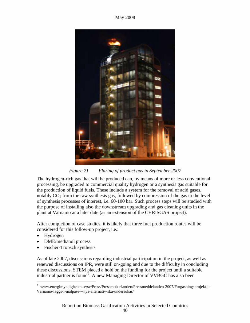
May 2008
Report on Biomass Gasification Activities in Selected Countries
Figure 21 Flaring of product gas in September 2007
The hydrogen-rich gas that will be produced can, by means of more or less conventional
processing, be upgraded to commercial quality hydrogen or a synthesis gas suitable for
the production of liquid fuels. These include a system for the removal of acid gases,
notably CO2 from the raw synthesis gas, followed by compression of the gas to the level
of synthesis processes of interest, i.e. 60-100 bar. Such process steps will be studied with
the purpose of installing also the downstream upgrading and gas cleaning units in the
plant at Värnamo at a later date (as an extension of the CHRISGAS project).
After completion of case studies, it is likely that three fuel production routes will be
considered for this follow-up project, i.e.:
Hydrogen
DME/methanol process
Fischer-Tropsch synthesis
As of late 2007, discussions regarding industrial participation in the project, as well as
renewed discussions on IPR, were still on-going and due to the difficulty in concluding
these discussions, STEM placed a hold on the funding for the project until a suitable
industrial partner is found2. A new Managing Director of VVBGC has also been
2 www.energimyndigheten.se/sv/Press/Pressmeddelanden/Pressmeddelanden-2007/Forgasningsprojekt-i-
Varnamo-laggs-i-malpase---nya-alternativ-ska-undersokas/
46
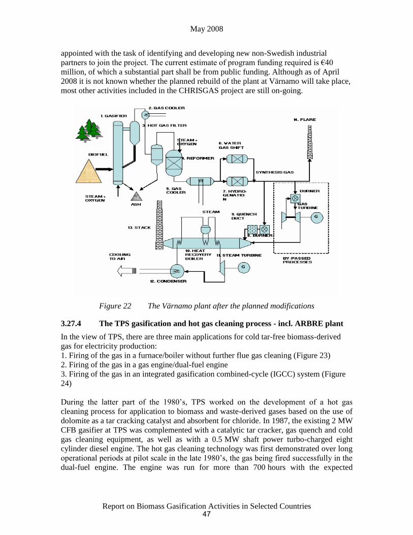
May 2008
Report on Biomass Gasification Activities in Selected Countries
appointed with the task of identifying and developing new non-Swedish industrial
partners to join the project. The current estimate of program funding required is €40
million, of which a substantial part shall be from public funding. Although as of April
2008 it is not known whether the planned rebuild of the plant at Värnamo will take place,
most other activities included in the CHRISGAS project are still on-going.
Figure 22 The Värnamo plant after the planned modifications
3.27.4 The TPS gasification and hot gas cleaning process - incl. ARBRE plant
In the view of TPS, there are three main applications for cold tar-free biomass-derived
gas for electricity production:
1. Firing of the gas in a furnace/boiler without further flue gas cleaning (Figure 23)
2. Firing of the gas in a gas engine/dual-fuel engine
3. Firing of the gas in an integrated gasification combined-cycle (IGCC) system (Figure
24)
During the latter part of the 1980’s, TPS worked on the development of a hot gas
cleaning process for application to biomass and waste-derived gases based on the use of
dolomite as a tar cracking catalyst and absorbent for chloride. In 1987, the existing 2 MW
CFB gasifier at TPS was complemented with a catalytic tar cracker, gas quench and cold
gas cleaning equipment, as well as with a 0.5 MW shaft power turbo-charged eight
cylinder diesel engine. The hot gas cleaning technology was first demonstrated over long
operational periods at pilot scale in the late 1980’s, the gas being fired successfully in the
dual-fuel engine. The engine was run for more than 700 hours with the expected
47

May 2008
Report on Biomass Gasification Activities in Selected Countries
efficiency, but yielded an exhaust gas with a relatively high concentration of CO and
hydrocarbons in comparison to combustion boilers.
TO FURNACE
DOLOMITEGAS
COOLER
FILTER
TAR CRACKER
GASIFIER
FUEL
AIR
AIR
Figure 23 TPS gasification and gas cleaning process scheme
Cracker
Air
Air
Gas turbine
Gas compressor
Gas purificationGasifier
DryerPreparation
Fuel
Fuel gas
Flue gas
Steam
turbine
Heat Recovery and
Steam Generation
Stack
G
Effluent
Fly ash
G
Electricity to local grid
Cooler evaporator
HT cooler
LT cooler
Figure 24 TPS CFBG IGCC process scheme
At that time, it was thought that a sizeable market existed in Sweden for the commercial
application of TPS’s gasification/hot gas cleaning technology to small-scale electricity
production plants (say 5 to 20 MWe). Although TPS did not succeed in selling any small-
scale plants based on this gasification/hot gas cleaning technology, TPS continued to
develop this application for IGCC systems and were successful in having its technology
selected for several important projects aimed at proving the technical and commercial
viability of biomass-fuelled IGCC systems (see below).
48

May 2008
Report on Biomass Gasification Activities in Selected Countries
3.27.4.1 Process description
The main advantage with gasification/dual-fuel engine is that a high yield of electricity
can be achieved in small-scale systems (30% efficiency at 3-10 MW). No commercial or
demonstration plants have yet been built.
As a part of the Brazilian project (see below), the TPS pilot plant was operated during ten
separate one-week tests. In April 1997, the gasifier and cracker were operated
continuously for four weeks with an availability of more than 90%. Up to 2002, further
tests were carried out on RDF and on sugar cane bagasse and trash, and mixtures of these
two fuels. In 2006, when TPS was relocating its offices, the pilot plant was demolished.
3.27.4.2 Projects and studies
In 1992, TPS was awarded a contract to further develop gasification technology for
application in a 30 MWe eucalyptus-fuelled IGCC plant to be built in North-eastern
Brazil. The development work was sponsored by, amongst others, the World Bank and
the Swedish National Board for Industrial and Technical Development (NUTEK), and
after 2000 also by the EC.
In 1995, the gasification development work was successfully completed and after an
evaluation of this technology and a competing pressurised gasification technology
proposed by Bioflow based on their experience from the Värnamo plant, TPS’s
technology was selected for use in the proposed plant. The General Electric LM 2500 gas
turbine, which was to be modified to accommodate the product gas from the gasifier, was
also selected for use.
A consortium for carrying out the project, SER, Sistemas de Energi Renovavel,
comprising of Shell Brasil, Eletrobrás and the local utility in Brazil CHESF, was
established but never became fully operative. With time, company policies and
perspectives changed and partners withdrew from the project. In early 2004, a private
company in Brazil interested in pursuing the project approached the World Bank for its
approval of this new arrangement, but the effort failed and the project was cancelled in
2004.
A similar project study in the Netherlands for UNA, the North Holland project was
conducted in the period 1993-1996 in cooperation with the Schelde group. The plant was
a similar size to that of the Brazilian plant and was meant to operate on a variety of waste
biomass. Again, the financing support failed and the project was terminated. TPS also
made a bid for the AMERGAS gasification plant together with Schelde, but the contract
was awarded to Lurgi.
Sugar cane bagasse
Apart from woody biomass, a huge potential for power generation from waste fuels exists
within the sugar cane industry. 1 200 million tonnes of sugar cane is harvested annually,
which corresponds to a worldwide electricity production potential of 40 000 MW or
300 TWh/annum in the eighty countries where sugar cane is grown on a significant basis.
49

May 2008
Report on Biomass Gasification Activities in Selected Countries
Project BRA/96/G31 - “Biomass Power Generation: Sugar Cane Bagasse and Trash” was
initiated in 1997 to evaluate and develop the technology required in the complete fuel-to-
electricity chain; starting with cultivation and recovery of sugar cane by-product fuels to
electric power generation with advanced systems (i.e. BIG-GT) integrated with a sugar
mill. The first phase of the project was organised as an extension of the eucalyptus-based
Brazilian BIG-GT project, financed roughly equally between Copersucar and GEF,
through UNDP. In 2000, additional support for an extension of the work was received
from the EU ENERGIE programme and STEM as part of the EU-BR-IDGE project.
Pilot plant tests on bagasse pellets were performed under two contracts, during 1998 and
1999, and the success of these tests led to an extension of the project, this extension also
being a part of the EU-BR-IDGE project The extension was to include test work on loose
sugar cane trash and was completed in 2001. On the basis of these tests, conceptual
engineering of a bagasse and cane trash-fuelled combined-cycle power plant integrated
with a typical sugar mill in Brazil was performed. However, plans to establish a
demonstration project in a sugar mill in Brazil, or Cuba, failed.
3.27.4.3 Project ARBRE
In 1993, the EU agreed to part-finance the construction of at least two short rotation
coppice-fuelled combined-cycle plants in Europe, each of 8 to 12 MWe capacity,
including Project ARBRE in the UK. (Figure24 )shows a simplified process flow
diagram of the plant.
In December 1994, the proposed plant became the recipient of an UK NFFO3
(Non-Fossil Fuel Obligation, 3rd tranche) contract providing an index-linked price of
8.75 p per kWh (1993, linked to the UK retail price index) guaranteed until 2013.
In December 1995, ARBRE Energy Limited (AEL), the majority owner of which were
Yorkshire water Plc, later to be renamed Kelda Plc, was formed to implement the plant
based on the following understanding of the role of AEL:
to contract with local farmers to cultivate, harvest and transport short rotation coppice
(SRC) to the generating plant
to contract with reputable fuel suppliers to deliver forestry residues to the generating
plant
to award a turnkey contract to a third party for design, construction, commissioning
and performance testing of the IGCC plant
to award a 15 year O&M contract to a third party
In the preparatory work for the RFP documentation, several important technical decisions
were made, including:
based on its proven use in similar applications, the Typhoon gas turbine from
Siemens. would be used
the plant would have a significant amount of supplementary firing in order to achieve
the desired 8 MWe output
the feedstock to the plant would be dried with the waste heat in the flue gas from the
gas turbine
50
May 2008
Report on Biomass Gasification Activities in Selected Countries
the process design of the gasification plant would be supplied by TPS through a
sub-contract to the turnkey contractor, the contract terms of which would be included
in the RFP documentation
The ARBRE plant is an IGCC plant comprised of the following major components:
wood delivery, weighing, reception/storage, drying and feeding
TPS atmospheric-pressure gasifier, including air supply
TPS hot gas conditioning vessel (so-called “tar cracker”)
fuel gas cooling
fuel gas cold cleaning (i.e. bag filter and wet scrubber)
fuel gas compressor
“Typhoon” gas turbine
waste heat boiler
steam turbine
The plant was to consume 43 000 dry tonnes of wood per year and its net electrical
efficiency was projected to be ca. 30%. This relatively low efficiency was a result of the
requirement of eligibility for the EU grant that net generation must reach 8 MWe, which
after selecting the technically proven Typhoon gas turbine of 4.5 MW could only be
achieved by increasing the contribution of the steam turbine cycle to the overall output by
firing a third of the gas produced directly into the HRSG, thereby bypassing the gas
turbine, such that the plant configuration was not an example of a typical generic
combined cycle.
Following the submission of an Environmental Statement in May 1996 and widespread
consultation with the local planning authority, local residents, the UK Department of
Energy and many other organisations, planning permission for the project was granted in
February 1997.
During 1996, the RFP documentation was issued and several companies submitted
preliminary offers. During 1996 and early 1997, detailed discussions took place with two
companies and in September 1997, a conditional turnkey contract, valued at ca. £23
million, was awarded to Schelde Engineers & Contractors BV, the Netherlands. At that
time, the planned start-up date for the plant was early 2000. McLellan and Partners, UK
was appointed as consulting engineer to the project and was responsible for managing the
turnkey contract.
In April 1998, and only after the plans for project financing had been abandoned and
replaced by majority financing by Kelda, could the turnkey contract be made
unconditional. At the same time, SEC signed the gasification process design sub-contract
with TPS. The plant’s O&M contract was awarded by AEL to Schelde Heat and Power
(SHP) UK Limited.
Fuel supply, preparation and feeding
The wood was to be delivered in chipped form to the plant by truck. The fuel supply,
preparation and feeding system consisted of a weigh-bridge, a reception pit, an A-frame
51

May 2008
Report on Biomass Gasification Activities in Selected Countries
storage building (providing three days bulk storage), a dryer (which dried the fuel to
around 10% moisture content with flue gases leaving the waste heat boiler) plus
travelling screws, screws and elevator and conveyors interconnecting these latter three
units and also leading to the two gasifier fuel feed silos.
Gas generation and tar cracking
The wood was to be fed to a TPS air-blown CFB gasifier operating at around 850°C and
at atmospheric pressure, and converted into a low calorific value gas.
The gas produced in the gasifier was to be cleansed of tars in a tar cracker; a second CFB
operating at a slightly higher temperature. By catalytically cracking the tar to simpler
compounds in this vessel, the gas can be cleansed of particulates and alkalis in
downstream conventional gas cleaning equipment. In addition, this catalytic process
means that there is no significant reduction in the chemical heating value of the gas, as
would be the case if the tar was thermally cracked at higher temperature.
Gas cooling, cleaning and compression
After leaving the tar cracker, the gas was to be cooled before passing through bag filters
at 200°C to remove fine particulates (fly ash, alkalis condensed on fly ash and chloride as
CaCl2). The gas would then be cooled further before the final cleaning stage. The heat
removed during the gas cooling stages would be recycled for boiler feedwater pre-heating
and steam raising. The final cleaning stage would be a wet scrubbing procedure to
condense out any remaining tars and water vapour and remove traces of alkali metals, as
well as to remove ammonia using a dilute sulphuric acid solution.
Power plant
The resulting clean gas would then be split into two streams and fed to the combined-
cycle generating plant.
The main gas stream would be compressed and fed to a Typhoon gas turbine with a rated
output of 4.75 MW. The hot gas turbine exhaust gases would then pass to a boiler for
heat recovery and steam generation. The Typhoon single-shaft industrial gas turbine is
designed specifically for electrical power generation and cogeneration applications. Its
application to biomass-produced fuel gas had already been proven in the Värnamo plant.
The second gas stream was to be combusted in the boiler to supplement the gas turbine
exhaust heat and generate additional steam. The steam raised in the boiler would then be
combined with that produced in the gas cooler and used to drive a 5.25 MW steam
turbine. The steam leaving the steam turbine would be condensed in a hybrid cooling
plant and returned to the boiler.
3.27.4.4 Construction and Commissioning of the Plant
Construction work on the site in Eggborough, North Yorkshire began in the spring of
1998.
During 1998, SEC’s parent company in the shipbuilding industry encountered such
serious economic difficulties that it was sold, and SEC was ultimately declared bankrupt.
52
May 2008
Report on Biomass Gasification Activities in Selected Countries
SEC’s obligations in relation to AEL gradually became impossible to meet and as a
result, construction of the plant suffered significant delays during 1998 and 1999. This
led to the cancellation of the O&M contract with SHP in 1999, and to AEL and SEC
agreeing in 2000 to terminate the turnkey contract. Prior to agreeing to terminate, the
start-up date for the plant had slipped to October 2000.
Following the departure of SEC from the project, AEL assumed direct responsibility for
plant construction as well as start-up and operation (the plant’s O&M activities were to
be managed by a team of 25 persons directly employed by AEL) and, at relatively short
notice, had to muster an engineering and site team to finalise the design and construction
of the plant. Difficulties encountered in completing the work meant that hot start-up
could only start in the beginning of 2001, and was then further delayed by inadequate
documentation and co-ordination between sub-contractors. Figure 25 shows the ARBRE
plant in June 2001.
3.27.4.5 Commissioning to mid. 2002
During commissioning, the plant suffered operational delays as a result of mechanical
problems. Most mechanical problems encountered were those associated with the
movement of solids, including fuel and ash. Most of these teething problems were easily
resolved, requiring only small modifications to the systems.
The fuel dryer operated without problems although its integrated operation with the rest
of the plant did lead to some difficulties. As more experience with its operation was
gained, the drying operation became more easily controlled.
The gasifier and tar cracker operated according to design, although operation in
gasification mode did not exceed 70% load, partly because of the limitation set by the gas
cooler (see later). The switchover from combustion mode to gasification mode was rapid
and trouble-free. The gasifier operated smoothly for a total period of more than
1 000 hours over ten test periods, each of varying duration. The fuels gasified included
many different wood species, including that from several of the SRC plantings.
53
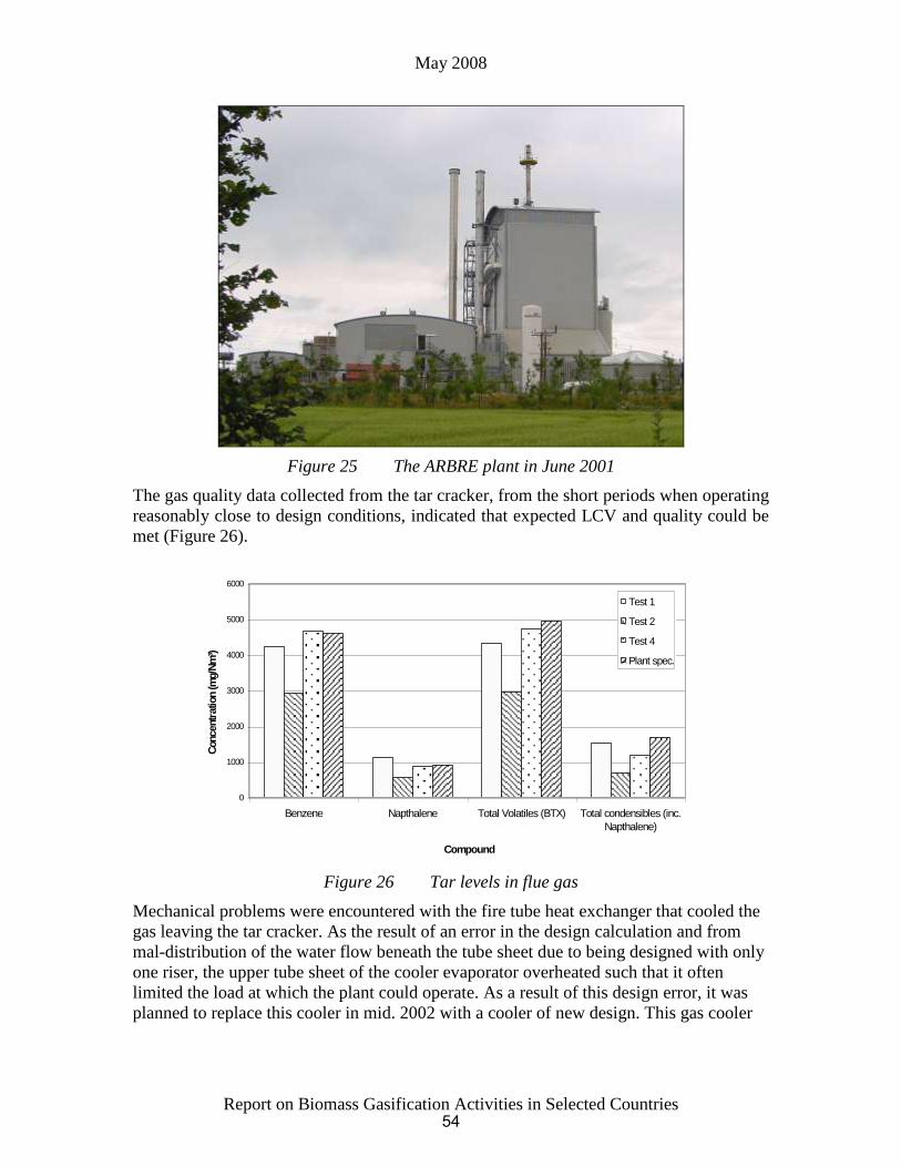
May 2008
Report on Biomass Gasification Activities in Selected Countries
Figure 25 The ARBRE plant in June 2001
The gas quality data collected from the tar cracker, from the short periods when operating
reasonably close to design conditions, indicated that expected LCV and quality could be
met (Figure 26).
0
1000
2000
3000
4000
5000
6000
Benzene Napthalene Total Volatiles (BTX) Total condensibles (inc.
Napthalene)
Compound
Concentr
ation (m
g/N
m³)
Test 1
Test 2
Test 4
Plant spec.
Figure 26 Tar levels in flue gas
Mechanical problems were encountered with the fire tube heat exchanger that cooled the
gas leaving the tar cracker. As the result of an error in the design calculation and from
mal-distribution of the water flow beneath the tube sheet due to being designed with only
one riser, the upper tube sheet of the cooler evaporator overheated such that it often
limited the load at which the plant could operate. As a result of this design error, it was
planned to replace this cooler in mid. 2002 with a cooler of new design. This gas cooler
54
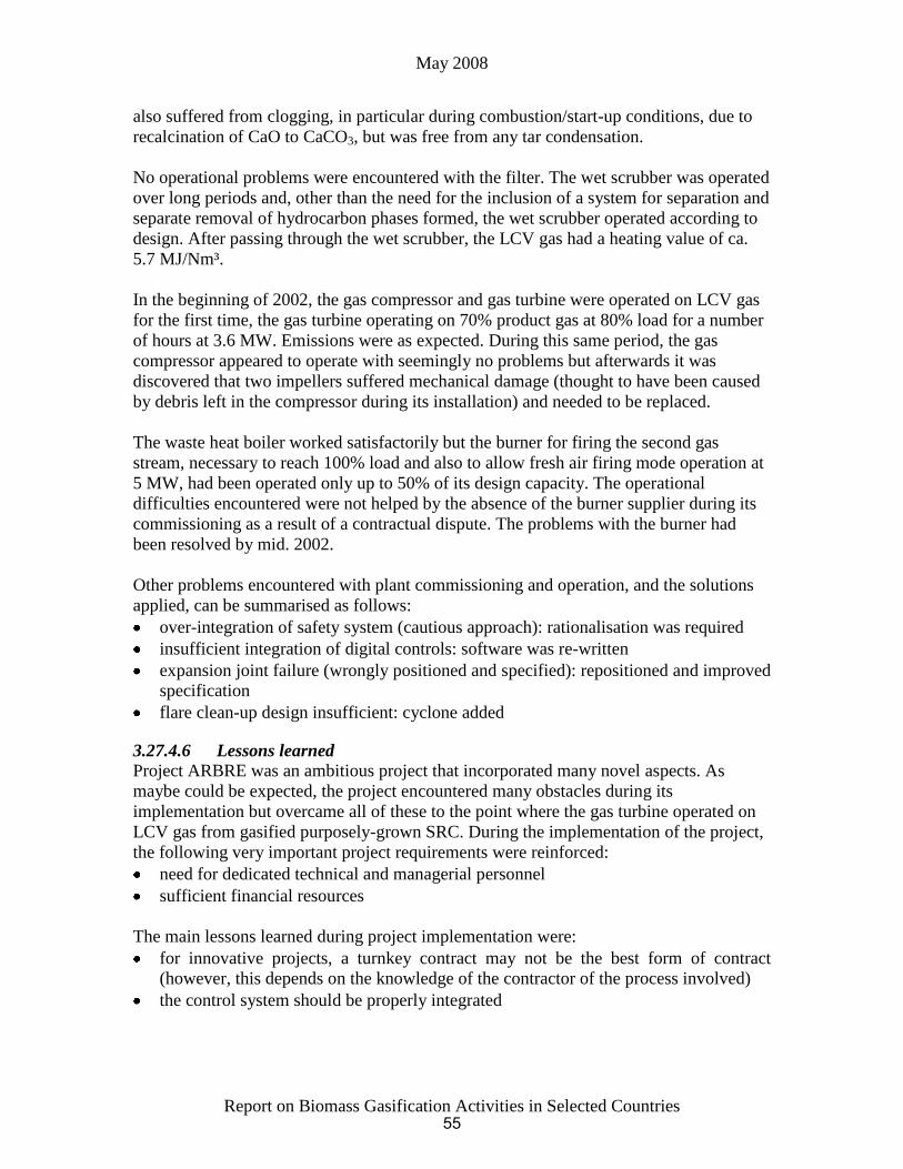
May 2008
Report on Biomass Gasification Activities in Selected Countries
also suffered from clogging, in particular during combustion/start-up conditions, due to
recalcination of CaO to CaCO3, but was free from any tar condensation.
No operational problems were encountered with the filter. The wet scrubber was operated
over long periods and, other than the need for the inclusion of a system for separation and
separate removal of hydrocarbon phases formed, the wet scrubber operated according to
design. After passing through the wet scrubber, the LCV gas had a heating value of ca.
5.7 MJ/Nm³.
In the beginning of 2002, the gas compressor and gas turbine were operated on LCV gas
for the first time, the gas turbine operating on 70% product gas at 80% load for a number
of hours at 3.6 MW. Emissions were as expected. During this same period, the gas
compressor appeared to operate with seemingly no problems but afterwards it was
discovered that two impellers suffered mechanical damage (thought to have been caused
by debris left in the compressor during its installation) and needed to be replaced.
The waste heat boiler worked satisfactorily but the burner for firing the second gas
stream, necessary to reach 100% load and also to allow fresh air firing mode operation at
5 MW, had been operated only up to 50% of its design capacity. The operational
difficulties encountered were not helped by the absence of the burner supplier during its
commissioning as a result of a contractual dispute. The problems with the burner had
been resolved by mid. 2002.
Other problems encountered with plant commissioning and operation, and the solutions
applied, can be summarised as follows:
over-integration of safety system (cautious approach): rationalisation was required
insufficient integration of digital controls: software was re-written
expansion joint failure (wrongly positioned and specified): repositioned and improved
specification
flare clean-up design insufficient: cyclone added
3.27.4.6 Lessons learned
Project ARBRE was an ambitious project that incorporated many novel aspects. As
maybe could be expected, the project encountered many obstacles during its
implementation but overcame all of these to the point where the gas turbine operated on
LCV gas from gasified purposely-grown SRC. During the implementation of the project,
the following very important project requirements were reinforced:
need for dedicated technical and managerial personnel
sufficient financial resources
The main lessons learned during project implementation were:
for innovative projects, a turnkey contract may not be the best form of contract
(however, this depends on the knowledge of the contractor of the process involved)
the control system should be properly integrated
55
May 2008
Report on Biomass Gasification Activities in Selected Countries
Project ARBRE has many positive operational aspects, the following being particularly
worthy of note:
fuel supply development demonstrated
process scale-up proven to be possible
no operational problems with CFB gasifier
no operational problems with catalytic tar cracker
LCV gas according to design specification
no operational problems with bag filters
no operational problems with gas turbine
3.27.4.7 Liquidation of ARBRE Energy Limited
ARBRE Energy Limited was placed in liquidation in summer 2002.
Ultimately, Project ARBRE failed as the result of insufficient dedicated managerial
personnel. Both SEC and Kelda became involved in Project ARBRE as a result of their
management’s wish to expand or change their core business, SEC moving from a
manufacturing basis to a project company in the new area of renewable energy and Kelda
expanding their none-regulated businesses and investing in renewables projects. Changes
in the management of both SEC and Kelda during the duration of Project ARBRE led to
both company’s changing their company strategy and ultimately withdrawing from
Project ARBRE.
During 2000, Kelda failed to receive permission from the regulatory authority for
requested price increases for water. This resulted in Kelda changing its strategy, and
deciding it would no longer invest in environmentally-oriented commercial development.
A consequence of this was that AEL was sold. From May 2002, AEL was owned by
Energy Power Resources (EPR) Limited of the UK, but the final takeover was
conditional on the success of operational trials at the end of 2002. The sale agreement
between Kelda and EPR included an effective write-off of a significant part of the loan
provided by Kelda to AEL, together with promised further write-offs once replacement
financing was put in place. The agreement also included a promise from Kelda to finance
the plant’s commissioning activities to the end of 2002.
In July 2002, Kelda withdrew its promise of support for plant commissioning to the end
of the year and despite the promising outlook for Project ARBRE as a result of the
reduction in loan debts, the preferential NFFO3 contract and the imminent commercial
operation of the plant, EPR decided to place AEL into immediate liquidation, citing
reasons of short term cash flow problem and long term economic viability. The EU, the
Department of Trade and Industry, UK (DTI) and STEM all expressed their concern over
the proposed liquidation of AEL and offered their assistance (including monetary
support) to prevent such a prospect. Despite these efforts and those made by other parties,
EPR placed the company in voluntary liquidation on 7 August 2002.
During the period September to November 2002, TPS had many contacts with companies
showing interest in “buying” Project ARBRE, most of which expressed the wish to see
56
May 2008
Report on Biomass Gasification Activities in Selected Countries
the project completed as originally intended. Several of these companies also held
discussions with the EU and the DTI on likely financial support.
In November 2002, bids were received from a number of companies and during
December and January 2003 serious discussions were held with interested parties,
following which new bids were to be received by mid. February 2003.
In April 2003, the sale of the assets of AEL to DAS Green Energy UK Ltd. (a subsidiary
of BDI of USA) was completed. Talks held in 2003 and 2004, and even as late as 2006,
between TPS and DAS Green Energy to complete Project ARBRE were unsuccessful.
The possibility for the plant to receive funding from the EU under existing contracts is no
longer available as these contracts have now expired.
As of April 2008, the fate of the ARBRE plant is not clear but it is unlikely that the plant
will ever be operated as it was originally intended.
3.27.5 Chemrec - www.chemrec.se
The Chemrec company was formed from the earlier SKF Plasma development company.
The plasma technology was bought by Kværner in 1990 and was a development company
within the Kværner Pulping organisation until 2000 when the majority of its shares were
sold to the German company Babcock Borsig Power. In 2002, Nykomb Synergetics
acquired the Babcock shares and became the majority owner. In 2003, Nykomb became
the sole owner of Chemrec after buying the remaining shares from Kværner.
In January 2007, AB Volvo (the truck company) through its daughter company Volvo
Technology Transfer (VTT) together with the California-based venture capital fund
Vantage Point Venture Partners (VPVP) took a 66% ownership position and injected new
capital into the company.
3.27.5.1 Technology
A major task of a Kraft recovery system is to recover cooking chemicals in a form
suitable for subsequent use in the delignification process. A conventional recovery
system has some limitations in this respect. Concepts such as split sulphidity pulping and
other sulphur-modified processes are difficult and costly to implement in existing
recovery systems.
The gasification-based recovery systems are more flexible, and cooking liquor
compositions ranging from sulphur saturated to low sulphidity or even sulphide-free
liquor may be obtained in quantities suitable for use in bleaching operations or for
sulphur-modified cooking.
The core of the Chemrec Kraft Recovery is the Chemrec gasifier - a refractory-lined
entrained flow reactor in which concentrated black liquor is gasified under reducing
conditions at around 1 000°C and 32 bar (Figure 27). The liquor is decomposed in the
reaction zone into melt droplets consisting of sodium compounds, and a combustible gas
containing CO, H2 and CO2.
57

May 2008
Report on Biomass Gasification Activities in Selected Countries
Figure 27 CHEMREC black liquor gasifier in DP-1 plant, see later
The smelt droplets and the combustible gas are separated in a quench dissolver, in which
they are simultaneously brought into direct contact with a cooling liquid. The melt
droplets dissolve in the liquid to form a green liquor solution. The gas leaving the quench
dissolver is cooled producing LP and IP steam. The cooling is done in counter current
mode which means that the gas is efficiently washed of particulate matters. The gas is
now free of melt droplets and can be scrubbed for H2S removal, and then used as a clean
fuel or syngas.
The three major applications for the CHEMREC™ Recovery technology are:
1. CHEMREC™ Booster
Relieve overloaded recovery boilers
Capacity expansion projects
2. CHEMREC™ - BLGCC
Replace old recovery systems (Tomlinson boiler)
Recovery technology for green-field mills with improved power yield
The CHEMREC BLGCC system utilises the syngas from the black liquor gasifier as feedstock for
electricity generation through combined cycle power generation. The CHEMREC BLGCC system has
several advantages over recovery boilers, the most significant being dramatically improved electricity
yield.
3. CHEMREC™ BLGMF/H2
Replace old recovery systems (Tomlinson boiler)
Recovery technology for green-field mills
Production of synthesis gas for production of black liquor gasification motor fuels
(BLMGF)
58

May 2008
Report on Biomass Gasification Activities in Selected Countries
The CHEMREC BLGMF system combines black liquor gasification with a chemical synthesis plant for
production of automotive fuels such as Methanol or DME. The new combined pulp and chemicals
production facility requires additional energy to compensate the pulp mill for the withdrawal of the new
automotive fuels. The efficiency of the CHEMREC BLGMF system for generating the new green
automotive fuels is very high.
The CHEMREC BLGH2 system utilises the syngas from the black liquor gasifier as feedstock for hydrogen
production.
Emerging recovery technologies based on gasification and energy recovery in advanced
gas turbine cycles promise substantial improvements in energy and environmental
performance. Besides a higher power to heat ratio, the CHEMREC™ IGCC system
(Table 8 and Figure 28) has a higher thermal efficiency relative to a recovery
boiler/steam cycle. This has a beneficial impact not only on emissions but also on the
supply of steam and power to the mill.
Table 8 CHEMREC™ vs. Recovery boiler, energy flows for co-generation
Modern recovery boiler CHEMREC™ IGCC
Electricity 14-16% 22%
Steam 54% ~50%
Losses ~30% 25-28%
The increased thermal efficiency and higher power to heat ratio in a CHEMREC™ IGCC
system increases the potential for power generation to the range 1.8-2.0 MWh/ADMT
(Air Dry Metric Tonne of pulp) from substantially lower figures in today’s most
advanced recovery boiler steam cycle systems. The current CHEMREC™ IGCC concept
is based on using oxygen as oxidant.
Figure 28 The CHEMREC™ BLGCC Technology
59

May 2008
Report on Biomass Gasification Activities in Selected Countries
Oxygen-blown gasification is an advantage in light of the increasing use of oxygen
chemicals in the modern mill. For the BLGMF concept, this is a prerequisite. When
considering synthetic motor fuels, the combination of synthesis gas generation with the
heat sinks available in the pulp mill means that not only can a good conversion efficiency
be achieved from black liquor, but more importantly, the extra biomass fuel required to
compensate for the loss of fuel value in the motor fuel product gives a > 65% conversion
efficiency. The cost of production of motor fuels is low due to the high biomass to fuel
conversion efficiency combined with a relatively low investment. A key reason for the
low investment is that the BLGMF technology (as well as BLGCC) is introduced in the
mill as a substitute for the recovery boiler at a time when it needs to be replaced.
3.27.5.2 Chemrec commercialisation
The Chemrec development milestones are highlighted in Figure 29.
A CHEMREC™ Booster atmospheric-pressure demonstration plant has been operating
successfully for some time at AssiDomän’s Frövifors mill in Sweden. The plant’s
capacity is 75 tonne per day of black liquor solids. The CHEMREC™ Booster system is
targeted to relieve overloaded recovery boilers, and unlike retrofitting a recovery boiler,
this system can be installed without any interruption in pulping operations. A commercial
facility of 300 tonne dry substance per day capacity (50 MW thermal rating) has been in
operation at the Weyerhauser New Bern pulp mill in USA since December 1996 (Figure
30). In the initial stage of operation, rapid refractory lining deterioration led to too short
intervals between ceramic replacements. The stainless steel reactor shell was cracked due
to SCC and taken out of service in 2000. After a long development and engineering
effort, a new carbon steel reactor with second generation refractory lining was installed
and the plant was restarted in June 2003. The new ceramic lining lasted 24 months before
it was replaced in October 2006. An even longer lifetime is expected for the current
lining. As of early 2008, the gasifier had clocked up 50 000 operating hours.
Figure 29 Chemrec development milestones, (A) atmospheric and (P) pressurised
plants
60

May 2008
Report on Biomass Gasification Activities in Selected Countries
Figure 30 Commercial Booster plant at New Bern
Gasification of black liquor under pressurised conditions, a pre-requisite for IGCC
operation based on the CHEMREC™ concept, has been performed and tested in a small
pilot plant in a mill in Karlstad, Sweden. A commercial-sized demonstration, planned in
1998-99 was delayed but allocated a grant from the Swedish state (237 million SEK, €26
million).
3.27.5.3 Pressurised facility DP-1
The €26 million grant from the Swedish state, together with co-financing from the
Swedish pulp & paper and utility industries as well as from the research foundation
MISTRA, was allocated to the construction of a pressurised development plant (Figure
31). The DP-1 is designed for gasification of about 20 dry tonnes/day of black liquor
(3 MW thermal rating) and operates at about 30 bar and 1 000ºC. DP-1 is located at the
Smurfit Kappa Kraftliner mill in Piteå, from which the black liquor is obtained and ETC
is a close neighbour to this mill site. DP-1 plant operation is managed by Chemrec and
during longer periods of operation supported by staff from the Kappa Kraftliner and SCA
Packaging Munksund mills. The first BLG Program during 2004-06 comprised the
construction, start-up and operation of DP-1 in parallel with the R&D program carried
out at five different universities and institutions. The budget for the three years was 101
million SEK (€11 million). A second phase, BLG II, started in January 2007 and will last
for another three years. The build up of the program is similar to the first part of the
program with strong connections between the R&D program and the operation of the
DP-1 plant. The budget for the second phase is approx. 85 million SEK (approx. €9
million).
61
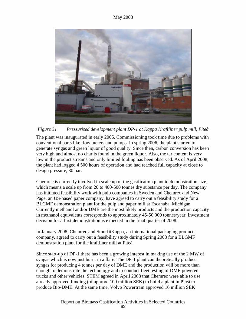
May 2008
Report on Biomass Gasification Activities in Selected Countries
Figure 31 Pressurised development plant DP-1 at Kappa Kraftliner pulp mill, Piteå
The plant was inaugurated in early 2005. Commissioning took time due to problems with
conventional parts like flow meters and pumps. In spring 2006, the plant started to
generate syngas and green liquor of good quality. Since then, carbon conversion has been
very high and almost no char is found in the green liquor. Also, the tar content is very
low in the product streams and only limited fouling has been observed. As of April 2008,
the plant had logged 4 500 hours of operation and had reached full capacity at close to
design pressure, 30 bar.
Chemrec is currently involved in scale up of the gasification plant to demonstration size,
which means a scale up from 20 to 400-500 tonnes dry substance per day. The company
has initiated feasibility work with pulp companies in Sweden and Chemrec and New
Page, an US-based paper company, have agreed to carry out a feasibility study for a
BLGMF demonstration plant for the pulp and paper mill at Escanaba, Michigan.
Currently methanol and/or DME are the most likely products and the production capacity
in methanol equivalents corresponds to approximately 45-50 000 tonnes/year. Investment
decision for a first demonstration is expected in the final quarter of 2008.
In January 2008, Chemrec and SmurfitKappa, an international packaging products
company, agreed to carry out a feasibility study during Spring 2008 for a BLGMF
demonstration plant for the kraftliner mill at Piteå.
Since start-up of DP-1 there has been a growing interest in making use of the 2 MW of
syngas which is now just burnt in a flare. The DP-1 plant can theoretically produce
syngas for producing 4 tonnes per day of DME and the production will be more than
enough to demonstrate the technology and to conduct fleet testing of DME powered
trucks and other vehicles. STEM agreed in April 2008 that Chemrec were able to use
already approved funding (of approx. 100 million SEK) to build a plant in Piteå to
produce Bio-DME. At the same time, Volvo Powertrain approved 16 million SEK
62

May 2008
Report on Biomass Gasification Activities in Selected Countries
funding to demonstrate the use of DME in their trucks. The go-ahead for the project,
named BioDME, that Volvo, Chemrec, Preem and ETC with three other partners will co-
operate on and which will be over a four year duration at a total cost of approx. €28
million, is conditional on receiving funding from the EU’s 7th Framework programme.
The decision from the EU is expected shortly.
3.27.6 Scanarc/Pyroarc (plasma) process - www.scanarc.se
The Plasma Gasification technique evolved from the metallurgical process developments
by SKF Steel in Sweden. In attempts to produce reducing gas for iron manufacture, a
plasma was introduced in the bottom of the shaft producing H2 and CO from coal and air.
The effectiveness of the plasma in this application was high, leading to a number of
proposed processes. Two of these processes were installed at full scale: the PlasmaZinc
and the PlasmaChrome for handling zinc dust and chrome materials. Several processes
for coal gasification using the Plasma Gasification technique were designed during the
early 1980’s, however none were realised.
Following the fall in energy prices during the 1980’s, the interest focused on Plasma
Gasification as a tool in waste handling, in particular, for special types of waste such as
hazardous wastes, medical wastes, etc.
The ScanArc (former “SKF Plasma”) process is a fixed bed, high temperature process
producing a molten slag. The gasification is carried out in an updraft shaft. Differences
with other processes are in the means to achieve the high temperature and in the cleaning
of the raw gas. In the ScanArc process, the gas cleaning is achieved in a plasma where
the gas is heated to very high temperatures, causing a decomposition of tar, chlorinated
hydrocarbons and ammonia.
3.27.6.1 Process description
The PyroArc process utilises the unique properties of plasma technology to achieve
complete decomposition of organic substances and to transform them into a clean fuel
gas. The process is suitable for nearly all types of waste including hazardous waste. The
PyroArc is well suited for recovery of metals and energy from hazardous waste
containing organic compounds (e.g. oil, dioxins, PCB, halogens) and/or heavy metals.
The pilot plant built in 1987 in Hofors, Sweden has tested a wide range of these types of
waste with good results. Solid waste is fed into the shaft gasifier through a lock hopper
system. The ScanArc process (Figure 32) uses a shaft reactor and is fed in the middle
with a mixture of air and oxygen. Non-combustible material is discharged from the shaft
as liquid slag or metal at about 1 450°C, while the gas, including halogenated aromatic
hydrocarbons, exits from the top of the gasifier at 400-600°C. Oxygen is needed when
the effective heat content of the wastes is too low to obtain a temperature of 1 200°C or
more. For fuels to the reactor with heat contents above 10-15 MJ/kg, this constitutes no
problem, however these heat contents are not always met with MSW unless other wastes
are added.
63

May 2008
Report on Biomass Gasification Activities in Selected Countries
Figure 32 SKF Plasma/ScanArc
The raw gas is fed to a second reactor, which is more or less an empty shaft with a
plasma generator on top. The electric plasma generates a theoretical temperature of more
than 15 000°C through which the gas is passed (thus, lowering the temperature) into the
shaft. The fuel to the plasma is composed of electricity and air for combustion
(oxidation). After the second reactor, chlorine is present as Cl2 or HCl, nitrogen as N2,
etc., i.e. all organic compounds and several others are decomposed.
After the plasma reactor, the gas is cooled and washed. The fly ash is collected and may
be sent for recovery of some metals since they are separated in a reduced state. Besides
the wash water, a “clean” gas and hot water is obtained. Available data do not provide
information as to what extent flue gas treatment is required after combustion.
Only few data are revealed from the process. The power consumption for the plasma,
depending on the heating value of the feed, is reported to be 200-400 kWh/tonne of feed.
These figures imply an energy efficiency of roughly 65-80%, calculated on the gas and
the hot water.
3.27.6.2 Status
The ScanArc gasification is tested on MSW in a pilot unit. The gasification is designed
for capacities of 50-100 000 tonnes per year and in this range the investments are
indicated to be US$ 700-1 000/tonne of feed (1997 figure). Offers have been made for
MSW plants, but no unit has yet been installed. At present, the ScanArc gasification
focuses on hazardous wastes where higher requirements on the process can more easily
afford the technique. There has been little apparent activity in Sweden during the last two
years.
64