swift-e swift-e+ 10kw-15kw load bank swift-e and swift-e+ load banks contain specially designed...
TRANSCRIPT

SWIFT-E
10KW-15KW LOAD BANK
SWIFT-E+


Page
1
Table of ContentsI. Warnings and Cautions ..................................................................................... 4II. Nameplates and Placards .................................................................................. 6
1. Introduction ......................................................................................................................... 62. Instruction Placards ........................................................................................................... 6
III. Description and Specification ........................................................................... 71. Introduction ......................................................................................................................... 72. Overview of Use .................................................................................................................. 73. Features ............................................................................................................................... 74. Safety ................................................................................................................................... 85. Specifications ..................................................................................................................... 8
IV. Unpacking ......................................................................................................... 101. Introduction ....................................................................................................................... 102. Included Components and Parts .................................................................................... 103. Primary Inspection ........................................................................................................... 10
V. Installation ..........................................................................................................111. Introduction ....................................................................................................................... 112. Load Bank Placement ...................................................................................................... 113. Wiring Connections .......................................................................................................... 13
VI. Operating Instructions ..................................................................................... 141. Introduction ....................................................................................................................... 142. Basic Operations .............................................................................................................. 14
VII. Alarms and Warnings ....................................................................................... 161. Introduction ....................................................................................................................... 162. Explanation of Failure ...................................................................................................... 163. Resolution for a Failure ................................................................................................... 164. Circuit Breaker Trips ........................................................................................................ 16
VIII. Diagnostics and Troubleshooting ................................................................... 181. Introduction ....................................................................................................................... 182. General Maintenance ....................................................................................................... 18
IX. Ordering Information ........................................................................................ 221. Swift-E or Swift-E+ (Circle Selection) ............................................................................. 222. Duffel Bag .......................................................................................................................... 223. Non-Standard Options .................................................................................................... 22
APPENDIX A — ABBREVIATIONS IN THIS MANUAL ..................................................................23APPENDIX B — TECHNICAL DATA ..............................................................................................24APPENDIX C — IMPORTANT FORMULA ......................................................................................28

Page
2
Table of FiguresI. Warnings and Cautions ..................................................................................... 4II. Nameplates and Placards .................................................................................. 6III. Description and Specification ........................................................................... 7
1. Table 1 ................................................................................................................................. 8IV. Unpacking ......................................................................................................... 10V. Installation ..........................................................................................................11
1. Figure 1 .............................................................................................................................. 112. Figure 2 .............................................................................................................................. 13
VI. Operating Instructions ..................................................................................... 141. Figure 3 .............................................................................................................................. 14
VII. Alarms and Warnings ....................................................................................... 16VIII. Diagnostics and Troubleshooting ................................................................... 18
1. Figure 4 .............................................................................................................................. 192. Figure 5 .............................................................................................................................. 193. Figure 6 .............................................................................................................................. 194. Table 2 ............................................................................................................................... 20
IX. Ordering Information ........................................................................................ 22

Page
3
Last Revision Date: February 21, 2013 For the most up-to-date information for this product and oth-
ers, please contact Simplex, Inc. at 1-217-483-1600 (Springfield, Il.) or 1-678-214-6575 (Atlanta, Ga.) or visit us on the web at
http://www.simplexdirect.com.
Page
4
1.0 WARNINGS AND CAUTIONSFour commonly used safety symbols accompany the DANGER, WARNING, and CAUTION blocks. The type of information each indicates is as follows:
This General warning symbol points out important safety infor-mation that, if not followed, could endanger personal safety and/or property of others.
This Explosion warning symbol points out potential explosion hazard(s).
This Fire warning symbol points out potential fire hazard(s).
This Electrical warning symbol points out potential electrical shock hazard(s).
Improper operation of this equipment such as neglecting its maintenance or being careless can cause possible injury or death. Permit only responsible and capable persons to install, operate, and/or maintain this equipment.
Potentially lethal voltages and amperages are present in these machines. Ensure all steps are taken to render the machine safe before attempting to work on the equipment.
ELECTRICAL WARNING
• All hardware covered by this manual have dangerous electrical voltages and can cause fatal electrical shock. Avoid contact with bare wires, terminals, connections, etc., on the hardware, if applicable. Ensure all appropriate covers, guards, grounds, and barriers are in place before operating the equipment. If work must be done around an operating unit, stand on an insulated dry surface to reduce shock hazard.
• Do not handle any kind of electrical device while standing in water, while barefoot, or while hands or feet are wet. DANGEROUS ELECTRICAL SHOCK MAY RESULT.
• If trained personnel must stand on metal or concrete while installing, servicing, ad-justing, or repairing this equipment, place insulative mats over a dry wooden plat-form. Work on the equipment only while standing on such insulative mats.
• The National Electrical Code (NEC), Article 250 requires the frame of the equipment to be connected to an approved earth ground and/or grounding rods. This grounding will help prevent dangerous electrical shock that might be caused by a ground fault condition or by static electricity. Never disconnect the ground wire.
• Wire gauge sizes of electrical wiring, cables, and cord sets must be adequate to han-dle the maximum electrical current (ampacity) to which they will be subjected.
• Before installing or servicing this (and related) equipment, make sure that all power voltage supplies are completely turned off at their source. Failure to do so will result

Page
5
in hazardous and possibly fatal electrical shock.
• In case of accident caused by electric shock, immediately shut down the source of electrical power. If this is not possible, attempt to free the victim from the live con-ductor. AVOID DIRECT CONTACT WITH THE VICTIM. Use a nonconducting implement, such as a dry rope or board, to free the victim from the live conductor. If the victim is unconscious, apply first aid and seek immediate medical attention.
• Never wear jewelry when working on this equipment. Jewelry can conduct electricity resulting in electric shock or may get caught in moving components causing injury.
FIRE WARNING
• Keep a fire extinguisher near the hardware at all times. Do NOT use any carbon tet-ra-chloride type extinguisher. Its fumes are toxic, and the liquid can deteriorate wir-ing insulation. Keep the extinguisher properly charged and be familiar with its use. If there are any questions pertaining to fire extinguishers, please consult the local fire department.
GENERAL WARNING
• The illustrations in this manual are examples only and may differ from your load bank.

Page
6
2.0 NAMEPLATES AND PLACARDS2.1 IntroductionThis section will provide copies of the nameplates and placards for the Swift-E and Swift-E+ Load Bank in the event that the current nameplates and placards become un-readable.
2.2 Instruction Placards

Page
7
3.0 DESCRIPTION AND SPECIFICATION3.1 IntroductionThis section will provide a brief synopsis of the use of the Simplex Swift-E Portable Load Bank. Simplex, Inc. reserves the right to change this synopsis, and this section should only serve as a brief concept of the device.In this section, you will find:
— An overview of normal usage of the Simplex Swift-E Portable Load Bank.
— An overview of hardware capabilities.
— An overview of safety functions.
3.2 Overview of UseThe Simplex Swift-E Portable Load Bank allows quick and easy testing of small genera-tors. The fully self-contained, lightweight and hand-transportable load bank can be used to test and maintain AC generators, AC rectifiers, inverters, power supplies, RV genera-tors, and other AC sources. The load bank is available as the standard 10KW Swift-E unit and the 15KW Swift-E+ unit. The Swift-E and Swift-E+ Load Banks contain specially designed power resistors, high temperature silicone insulated power wiring, industrial toggle switches, high-interrupt-ing capacity fuses, and load connection cables. All control and cooling circuits operate from the source under test. The Swift-E and Swift-E+ Load Banks are completely self-con-tained and portable, rugged test instruments. Complete test instrumentation and con-nection cables are provided.For a parts legend, please See “8.2 General Maintenance” on page 18. Always consult the parts legend drawing or “9.0 Ordering Information” on page 22 when ordering parts for a Swift-E or Swift-E+ Load Bank. The referenced illustration is for example only and shouldn’t be used for diagnostic purposes.
3.3 FeaturesIn interest of safety, the Swift-E unit includes sealed tubular-type load elements that are made up of nickel-chromium resistance wire, which is sealed in incoloy sheath (nickel alloy). In order to reduce the hazard of electrical shock and short circuiting of elements, the element has a nonconductive exterior. The element is also rustproof, vibration proof, and shock proof.Using the panel-mounted toggle switches for each load step as well as master load control, the load bank performs precise load control. For master load control as well as block loading, the Swift-E Load Bank contains main contactors for full control. In the interest of preventing overload and short circuit protection, the load bank has a main circuit breaker.With a connection cable set of 10’ with ring lug terminations, the load bank is also en-cased in a NEMA, type 1 enclosure of aluminum construction with exterior powder coating. In addition, the enclosure has protective rubber feet, handles for carrying, and cable wrap for neat storage.

Page
8
3.4 SafetyTo prevent a situation where the temperature is too high and damages the hardware or presents a dangerous scenario for operators, the Swift-E and Swift-E+ have an over-tem-perature sensor to trip the main contactor and activate the alarm indicator. Should the connection of the load bank be incorrectly installed, an over-voltage sensor is in place that will also trip the main contactor and activate the previously mentioned alarm indi-cator.
3.5 Specifications AC Ratings:
Model Ratings Description
Swift-E 10KW 120/240V, Single-Phase, 250W Step Resolution
Swift-E+ 15KW 120/240V, Single-Phase, 250W Step Resolution
Table 1

Page
9
Did You Know?
Simplex was founded in 1938 in Burlington, Iowa by Michael Debrey, a Hungarian immigrant. A self-taught inventor, Debrey introduced multiple innovations to the electrical engineering field, including the Automatic Voltage Regulator. Simplex was moved to East Moline, Illinois, where it remained until 1951, when the company relocated to Springfield, Illinois.

Page
10
4.0 UNPACKING4.1 IntroductionThis section will detail the procedure to unpack the Swift-E Load Bank. This guide will include preparation for setting up the equipment for proper use.In this section, you will find:
— A list of included components and parts.
— An inspection list.
4.2 Included Components and PartsThe following items are included with your Swift-E or Swift-E+ Load Bank. If the following is not included, please contact your Simplex representative or call Simplex Direct, Inc., at 217-483-1600.• Manual
• Swift-E Load Bank
4.3 Primary InspectionPreventative visual inspection of the shipping crate and the Load Bank is advised. Phys-ical or electrical problems due to handling and vibration may occur. Never apply power to a load bank before performing this procedure. The following five-point inspection is recommended before installation and as part of the 50-hour / 6-month maintenance schedule or as a Load Bank is relocated:
1. If the crate shows any signs of damage, examine the load bank in the corre-sponding areas for signs of initial problems.
2. Check the entire outside of the cabinet for any visual damage, which could cause internal electrical or mechanical problems due to reduced clearance.
3. Inspect all relays and control modules. Make sure all components are secure in their bases and safety bails are in place. Spot check electrical connections for tightness. If any loose connections are found, inspect and tighten all remaining connections.
4. Examine all accessible internal electrical components such as fuses, contactors, and relays. Check lugged wires at these components.
5. Visually inspect element chamber for foreign objects, broken ceramic insula-tors, and mechanical damage.
If any problems are observed during Primary Inspection, call the Simplex Service Manager at 217-483-1600 (24hrs), ext. 110.
Page
11
5.0 INSTALLATION5.1 IntroductionWhen using the Swift-E Load Bank, location is imperative in order to prevent damage to the load bank as well as safeguard against any injury. In this section, you will find:
— How to choose the load bank’s location.
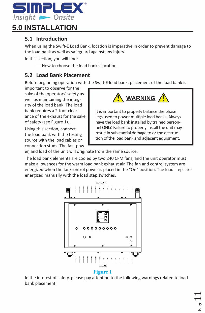
5.2 Load Bank PlacementBefore beginning operation with the Swift-E load bank, placement of the load bank is important to observe for the sake of the operators’ safety as well as maintaining the integ-rity of the load bank. The load bank requires a 2-foot clear-ance of the exhaust for the sake of safety (see Figure 1).Using this section, connect the load bank with the testing source with the load cables or connection studs. The fan, pow-er, and load of the unit will originate from the same source.The load bank elements are cooled by two 240 CFM fans, and the unit operator must make allowances for the warm load bank exhaust air. The fan and control system are energized when the fan/control power is placed in the “On” position. The load steps are energized manually with the load step switches.
Figure 1In the interest of safety, please pay attention to the following warnings related to load bank placement.
WARNING
It is important to properly balance the phase legs used to power multiple load banks. Always have the load bank installed by trained person-nel ONLY. Failure to properly install the unit may result in substantial damage to or the destruc-tion of the load bank and adjacent equipment.
Page
12
WARNING
Note: Load Bank warranty is void if incorrectly cooled.High Voltage: Turn off and disconnect power source before opening this compartment.High Temperature: Allow equipment to cool before servicing or opening this compart-ment.Rotating Equipment: Ensure that fan(s) has stopped before opening this compartment.For Operator Safety: Make sure this equipment is properly grounded when in use.All compression type connections on fuse blocks, load blocks, and contactors where used, should be checked for tightness frequently. This check should be established as part of routine maintenance.During operation, hot exhaust air must exit from the “top” of the load bank (see Figure 1). If not, shut down the load bank immediately. Correct the problem before applying power to the load bank. This load bank is high-powered, technical, industrial equipment operating at dangerous voltages and temperatures. It is capable of damage to itself or property or personnel if improperly used. It is not a consumer product.It must be installed, connected and operated by personnel properly trained and expe-rienced in its use. An operator’s manual is supplied with each load bank or available Online at http://www.simplexdirect.com.It is imperative that the operator be familiar with its contents and has access to it during operation.The following cautions should be observed before and during operation:
1. Check intake and exhaust screens as well as fan and load elements for foreign objects.
2. Position and install load bank with great consideration given to large cubic air-flow requirements, exhaust temperature and velocity. Therefore, do not point exhaust at any nearby surface or object, which may be adversely affected by high temperature. This includes but is not limited to painted surfaces, tarpaper and asphalt roofs, water sprinkler heads, fire alarms, and volatile material.
Do not use in confined spaces without due regard for an adequate supply of intake air and provision for exit of high temperature exhaust. Do not permit vertical airflow unit with wheels to sink into soft surfaces thereby cutting off bottom air intake. Be concerned with possibility that the load bank may have to compete with cooling air requirements of a nearby running engine generator set where cooling air intake to a confined space may not be ade-quate for both engine and load bank. Be especially careful not to bounce hot exhaust air off nearby obstructions for re-circulation through the load bank.
3. Verify that all control switch positions are correct for intended usage before mak-ing connection.
4. The load cables carry high amperage. Be constantly aware of possibility of in-ductively heating adjacent ferrous objects to temperatures sufficient to damage

Page
13
cable insulation.
5. Always connect safety ground cable to a proper ground. Do not rely on a possible grounded neutral somewhere else in the system.
6. Do not let equipment operate unattended for long periods of time.
7. Do not store or operate in rain adequate protection is provided.
8. Routinely inspect all components and electrical connections for tightness and integrity.
9. Repair any damaged or degraded components and wiring without delay.
If technical assistance, service or parts are needed, please call 800-837-8603 (24 Hours).
5.3 Wiring ConnectionsUsing the connection chart found on the Swift-E and Swift-E+ Load Banks nameplates (Figure 2), wire the load bank to the desired source for testing.
Figure 2
Page
14
6.0 OPERATING INSTRUCTIONS6.1 IntroductionBecause the Swift-E and Swift-E+ Load Bank was designed with simplicity in mind, the hardware is easy to maintain and use.The Swift-E and Swift-E+ Load Banks have discrete load steps to increase the applied load as desired.In this section, you will find:
— How to properly handle the unit.
— How to start the load bank.
— How to apply a load using the equipment.
6.2 Basic OperationsPrior to operating the Swift-E Load Bank, ensure that the unit is wired properly based on the instructions from “5.2 Load Bank Placement” on page 11 as well as “2.2 Instruc-tion Placards” on page 6 for the placard with wiring directions.
6.2.1 Startup1. When wired appropriately, the unit is ready to apply a load to a
test source. To perform this task, using the toggle switch, select the input value in the Meter Range section of the Swift-E and Swift-E+ nameplate. The values are either 120V or 240V.
2. Flip the toggle switch to “On” for the Fan/Control selection. If the system is operating properly, you will hear the fans start and the Datakom monitoring pan-el will illuminate.
6.2.2 Applying a Load1. Flip the toggle switch
under “Master” to “On.” This will allow the user to begin applying load to the source as each load step is activated.
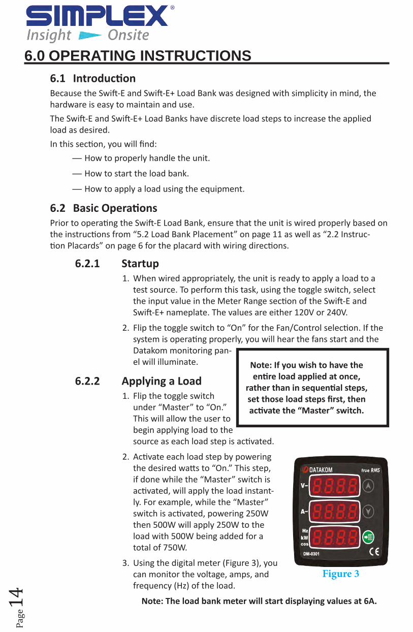
2. Activate each load step by powering the desired watts to “On.” This step, if done while the “Master” switch is activated, will apply the load instant-ly. For example, while the “Master” switch is activated, powering 250W then 500W will apply 250W to the load with 500W being added for a total of 750W.
3. Using the digital meter (Figure 3), you can monitor the voltage, amps, and frequency (Hz) of the load.
Note: The load bank meter will start displaying values at 6A.
Note: If you wish to have the entire load applied at once,
rather than in sequential steps, set those load steps first, then activate the “Master” switch.
Figure 3
Page
15
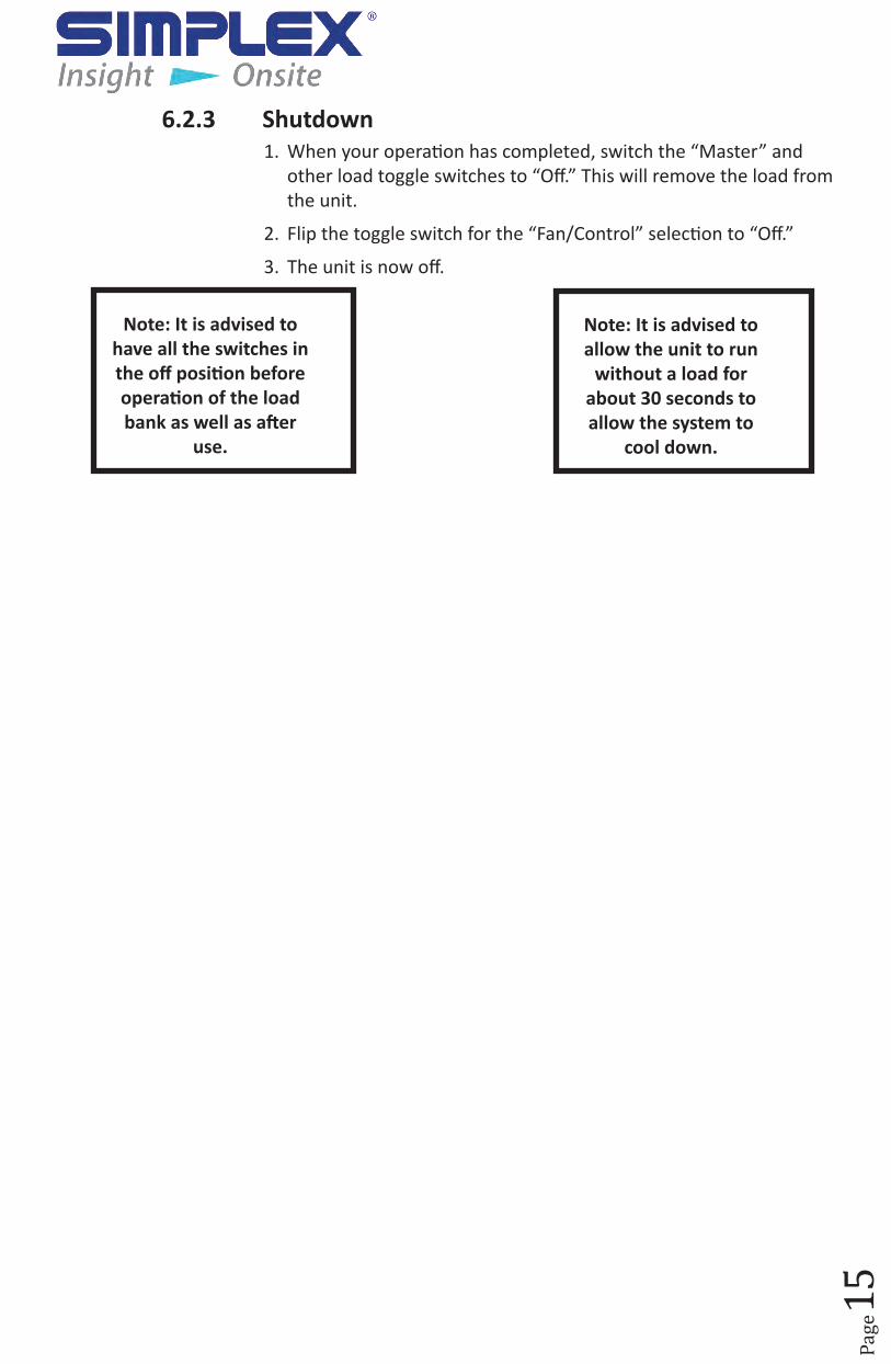
6.2.3 Shutdown1. When your operation has completed, switch the “Master” and
other load toggle switches to “Off.” This will remove the load from the unit.
2. Flip the toggle switch for the “Fan/Control” selection to “Off.”
3. The unit is now off.
Note: It is advised to allow the unit to run
without a load for about 30 seconds to allow the system to
cool down.
Note: It is advised to have all the switches in the off position before operation of the load bank as well as after
use.

Page
16
7.0 ALARMS AND WARNINGS7.1 IntroductionWith its simple design in the interest of efficiency, The Swift-E Load Bank has few areas for failure. In the unlikely event that an issue arises, you will find how to address these issues in this section.In this section, you will learn:
— Common alarms and warnings and how to address them.
7.2 Explanation of FailureIf the load bank exhaust air exceeds the set point (175° F) of the exhaust temperature switch (EXTS), a cooling failure is initiated. The Swift-E and Swift-E+ Load Banks control circuitry de-energizes the load steps during a cooling fail-ure. Cooling failure relay contacts in series with the cooling failure lamp close, and the lamp is illuminated.
7.3 Resolution for a FailureIf the over temperature alarm is triggered, the Swift-E Load Bank should be reset by power cycling the unit—powering completely down then powering it back on. The unit should be off for a couple of seconds. Before restarting the unit, check for the cause of failure. This step is imperative for the safety of the unit and load bank operators.
7.4 Circuit Breaker TripsIf the circuit breaker is tripped, remove the six (6) faceplate screws on the unit to access the circuit breaker.
Note: It is important to in-vestigate all cooling failures. Unresolved cooling issues can cause serious issues later in the load bank’s life cycle.

Page
17
Did You Know?
Simplex Onsite has the only factory trained technicians for Simplex load banks and fuel systems. Simplex Onsite not only provides service for new and existing load banks and fuel sys-tems but offers a full line of rental load banks, transformers and cables up to 15KV. Simplex Onsite is a division of Simplex so unlike other load bank rental companies our load banks are designed specifi-cally for Simplex Onsite Inc. We are not using multiple manu-factures of load banks and equipment that is not designed for rental applications.

Page
18
8.0 DIAGNOSTICS AND TROUBLESHOOTING8.1 IntroductionThrough good practice, cumulative issues can be prevented through basic maintenance. In the unlikely event that something goes wrong with your Simplex Load Bank, we will cover how to solve some of the more common problems. Finally, if the need arises, we will cover how to replace various parts for the Swift-E Load Bank.In this section, you will learn:
— How to perform preventative maintenance on the load bank.
— Some of the common issues you may run into and how to troubleshoot these items independently.
— About the part names, the part numbers, and what each primary function is in the Swift-E(+) Load Banks.
8.2 General MaintenanceAll electrical connections should be tightened every 6 months. Cooling fan motors are permanently lubricated and do not require maintenance.
WARNING
Always remove all power from the load bank and all fan/control power before servicing the load bank. Never operate or service a load bank that is not properly connected to an earth-ground.
WARNING
If a failure occurs during load bank opera-tion, the load bank will de-energize all load steps. The operator must reset the load bank by turning it “Off” then “On.” The load failure must be investigated and cor-rected before load application can resume.

Page
19
Figure 6
Figure 5
Figure 4
Page
20
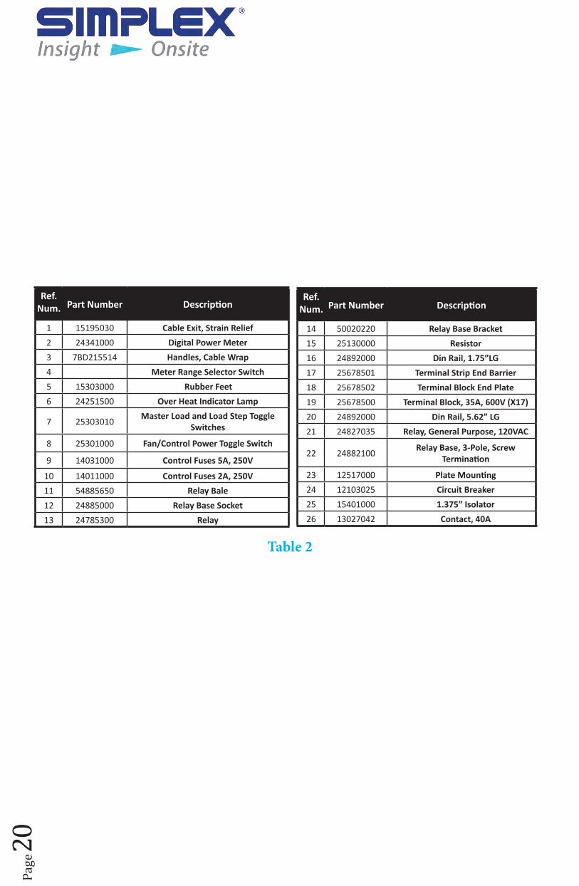
Ref. Num. Part Number Description
1 15195030 Cable Exit, Strain Relief2 24341000 Digital Power Meter3 7BD215514 Handles, Cable Wrap4 Meter Range Selector Switch5 15303000 Rubber Feet6 24251500 Over Heat Indicator Lamp
7 25303010 Master Load and Load Step Toggle Switches
8 25301000 Fan/Control Power Toggle Switch
9 14031000 Control Fuses 5A, 250V
10 14011000 Control Fuses 2A, 250V11 54885650 Relay Bale12 24885000 Relay Base Socket13 24785300 Relay
Ref. Num. Part Number Description
14 50020220 Relay Base Bracket15 25130000 Resistor16 24892000 Din Rail, 1.75”LG17 25678501 Terminal Strip End Barrier18 25678502 Terminal Block End Plate19 25678500 Terminal Block, 35A, 600V (X17)20 24892000 Din Rail, 5.62” LG21 24827035 Relay, General Purpose, 120VAC
22 24882100 Relay Base, 3-Pole, Screw Termination
23 12517000 Plate Mounting24 12103025 Circuit Breaker25 15401000 1.375” Isolator26 13027042 Contact, 40A
Table 2

Page
21
Did You Know?
Load banks simulate the “real world” loads that the power source will experience. Electrical load can be broadly classified as resistive, magnetic and capacitive. In the real world, these components are mixed, as they are with a load bank, except with the load bank, full control of the components is possible.The most common load bank and the load bank which is suitable for general load testing is the resistive load bank. A resistive load bank converts electrical energy to heat. Within the load bank, the load is divided into discrete circuits or “steps” capable of stepwise, controlled application. The load bank includes a means of cooling, most commonly forced air, but also water.

Page
22
9.0 ORDERING INFORMATIONThis section will serve as a guide to assist in the proper component selection for your Swift-E Portable Load Bank. The options below are for the standard models. For any cus-tom orders or for any clarification or questions on the items, please contact your Sim-plex Inc. representative. When ordering, please attach your purchase order to this form and fax it to Simplex, Inc. at 217-483-1616 or call Simplex, Inc. at 217-483-1600.
9.1 Swift-E or Swift-E+ (Circle Selection)
Swift-E OR Swift-E+KW
Capacity10KW 15KW
Voltage single-phase, 120V or 240VWeight 45 lbs
Dimensions 20”W x 17.75”H x 14”D
9.2 Duffel Bag Duffel Bag: YES OR NO
9.3 Non-Standard Options Add: CAM-LOK connectors (YES OR NO) Add: Nema Plugs (YES OR NO) Add: Clamps (YES OR NO)
Customer Name: P.O. #:
Fax to 217-483-1616
(Note: Using the following items will require customized work and create a longer lead time as they are not on stock models.)

Page
23
Appendix A — ABBReViATiOnS in THiS MAnUAL
Listed below are abbreviations of terms found for the Swift-E and the Swift-E+ Load Banks. When following a drawing, utilize this guide to define abbreviated system and component names. As this is a master list, drawings and text pertaining to your equipment may not con-tain all these terms.
- GroundA - Amps; AmperageCFM - Cubic Feet per MinuteF - FahrenheitHz - Hertz; FrequencyKW - Kilowatts V - Volts; VoltageVAC - Voltage, Alternating CurrentW - Watts; Wattage

Page
24
Appendix B — TeCHniCAL dATA
Swift-E Schematics

Page
25

Page
26
Swift-E+ Schematics

Page
27

Page
28
Appendix C — iMpORTAnT FORMULAOHMS LAW:
OHMS = VOLTS / AMPS ( R = E / I)AMPS = VOLTS / OHMS (I = E / R) VOLTS = AMPS / OHMS (E = IR)
3 PhaseResistance = (V² X 2) / W Amperage = W / (V X 1.732)
208V KW 1 5 10 20 25 40 50 100 200 250 400 500RES 86.5 17.3 8.6 4.3 3.46 2.16 1.73 0.865 0.432 0.346 0.276 0.173
AMP 2.77 13.9 27.8 55.5 69.4 111 139 278 555 694 1110 1388
240V KW 1 5 10 20 25 40 50 100 200 250 400 500RES 115 23.0 11.5 5.76 4.61 2.88 2.30 1.15 0.576 0.461 0.288 0.230
AMP 2.41 12.0 24.0 48.0 60.0 96.2 120 240 480 600 962 1200
380V KW 1 5 10 20 25 40 50 100 200 250 400 500RES 289 57.7 28.8 14.4 11.5 7.22 5.77 2.88 1.44 1.15 0.722 0.577
AMP 1.51 7.59 15.2 30.4 37.9 60.7 75.9 152 304 380 608 760
480V KW 1 5 10 20 25 40 50 100 200 250 400 500RES 460.8 92.2 46.1 23.0 18.4 11.5 9.22 4.61 2.30 1.84 1.15 0.922
AMP 1.20 6.01 12.0 24.0 30.0 48.1 60.0 120 240 300 481 6001 PhaseResistance = V² / W Amperage = W/ V
120V KW 1 5 10 20 25 50 100 200 250 500RES 57.6 28.8 14.4 7.20 4.80 3.60 2.88 1.44 0.720 0.360
AMP 2.08 4.16 8.33 16.7 25.0 33.3 41.7 83.3 167 333
208V KW 1 5 10 20 25 50 100 200 250 500RES 43.3 8.65 4.33 2.16 1.73 0.865 0.432 0.216 0.173 0.086
AMP 4.80 24.0 48.1 96.1 120 240 481 962 1202 2404
240V KW 1 5 10 20 25 50 100 200 250 500RES 57.6 11.5 5.8 2.88 2.30 1.15 0.576 0.288 0.230 0.115
AMP 4.16 20.8 41.6 83.3 104 208 417 833 1042 2083
KVA: 1 phase VOLTS X AMPS 3 phase 1.732 X VOLTS X AMPSDerating KW: KW(V2 / V1)² = deated KW; EX. 50KW (200/240)² = 34.722KWDerating KW and Hz: KW (V2/V1)² X (F1/F2) = Derated KW at different Hz3 Phase Henrys: V²/(Kvar X 3.14 X freq) 1 Phase Henrys: V²/(2 X 3.14 X freq X vars)1 Phase Farads: Kvar / (2 X 3.14 X freq X V²)MA Outputamps: amps / (833 X 16 + 4) volt: (V2 / V1) X 16 + 4
Heater Current (Wye)IH = WH * (VL-H/(XH*VH²))IH = Heater CurrentWH = Wattage of 1 HeaterXH = # of Heaters from Line to NeturalVH = Rated Voltage of 1 Heater Fuses for TransformerTotal Amperage = V*A / Source Voltage
Page
29
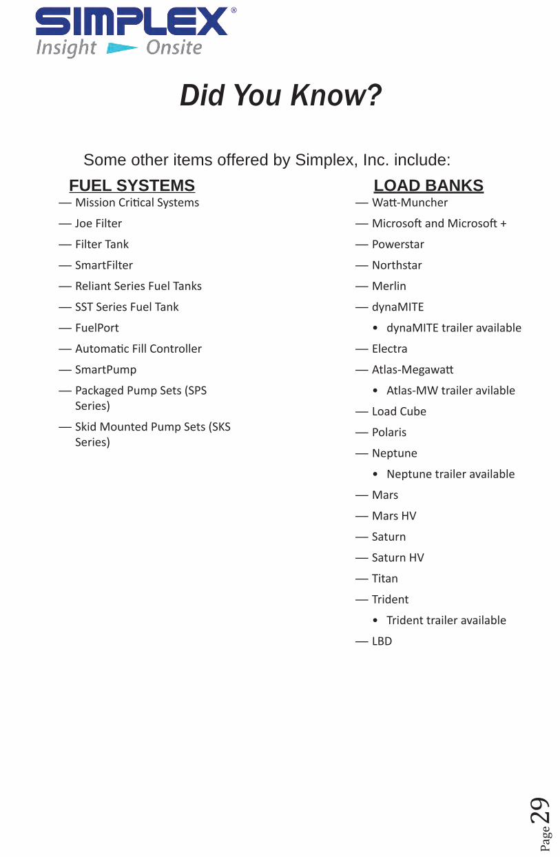
Did You Know?
Some other items offered by Simplex, Inc. include:
FUeL SYSTeMS — Mission Critical Systems
— Joe Filter
— Filter Tank
— SmartFilter
— Reliant Series Fuel Tanks
— SST Series Fuel Tank
— FuelPort
— Automatic Fill Controller
— SmartPump
— Packaged Pump Sets (SPS Series)
— Skid Mounted Pump Sets (SKS Series)
LOAd BAnKS — Watt-Muncher
— Microsoft and Microsoft +
— Powerstar
— Northstar
— Merlin
— dynaMITE
• dynaMITE trailer available
— Electra
— Atlas-Megawatt
• Atlas-MW trailer avilable
— Load Cube
— Polaris
— Neptune
• Neptune trailer available
— Mars
— Mars HV
— Saturn
— Saturn HV
— Titan
— Trident
• Trident trailer available
— LBD

Simplex, Inc.270 Riverside Parkway, Suite G
Austell, GA 30168(678) 214-6575
5300 Rising Moon RoadSpringfield, IL 62711(217) 483-1600 (24hrs)
http://www.simplexdirect.com