swing check body - flowserve corporation
TRANSCRIPT

INSTRUCTION MANUAL
Anchor Darling Swing Check Sizes 2-1/2” through 24”
FCD ADENIM0013-00
Installation
Operation
Maintenance

Swing Check Valves FCD ADENIM0013-00
1
REVISION RECORD
Revision Section Description Date
- All Original Issue 09/18/2003

Swing Check Valves FCD ADENIM0013-00
2
TABLE OF CONTENTS
1.0 VALVE DESCRIPTION Page
1.1 Recommended Uses .................................................5
1.2 Principles of Operation ..............................................5
1.3 Design Features ......................................................6
1.3.1 Bonnet Seals ...............................................6
1.3.2 Disc Assembly and Seats............................7
1.3.3 Seat ......................................................8
2.0 CARE OF VALVE PRIOR TO INSTALLATION
2.1 Receiving Inspection..................................................8
2.2 Handling ..................................................................9
2.3 Storage ..................................................................9
3.0 INSTALLATION INSTRUCTIONS
3.1 Rigging .....................................................................9
3.2 Cleaning .....................................................................9
3.3 Installing Valve In Line...............................................9
4.0 VALVE MAINTENANCE
4.1 Inspection .......................................................10
4.2 Cleaning .......................................................10
4.3 Bolt Torquing ........................................................10
4.4 Refinish Sealing Surfaces........................................10
Swing Check Valves FCD ADENIM0013-00
3
TABLE OF CONTENTS
5.0 DISASSEMBLY Page
5.1 Flanged Bonnet Valves.......................................................... 11
5.1.1 Bonnet .................................................................. 11
5.1.2 Disc Assembly......................................................... 13
5.1.2.1 Configuration A ......................................... 13
5.1.2.1.1 Pipe Plug Seal Cover .............. 14
5.1.2.1.2 Pressure Seal Cover ............... 15
5.1.2.1.3 Blind Cover Flange.................. 15
5.1.2.2 Configuration B ...................................... 16
5.1.2.3 Configuration C ...................................... 17
5.1.2.4 Disc/Hinge Assembly ................................ 18
5.2 Pressure Seal Bonnet Valves ................................................ 19
5.2.1 Bonnet .................................................................. 19
5.2.2 Disc Assembly......................................................... 19
6.0 ASSEMBLY
6.1 Flanged Bonnet Valves.......................................................... 21
6.1.1 Disc Assembly......................................................... 21
6.1.1.1 Disc/Hinge Connection.............................. 21
6.1.1.2 Hinge Mounting ......................................... 22
6.1.1.2.1 Pin Mounted in Body Wall ......... 22
6.1.1.2.2 Bracket Pin on Bonnet .............. 24
6.1.1.2.3 Bracket Pin in Body................... 25
6.1.2 Bonnet ..................................................................... 26
6.2 Pressure Seal Bonnet Valves ................................................ 27
6.2.1 Disc Assembly......................................................... 27
6.2.2 Bonnet ..................................................................... 28
Swing Check Valves FCD ADENIM0013-00
4
Swing Check Valves FCD ADENIM0013-00
5
1.0 VALVE DESCRIPTION
1.1 Recommended Uses
Anchor/Darling Swing Check Valves are designed to prevent the reversal of flow in a piping system. While they
may hold pressure in the reverse direction, they are not intended for use as isolation valves without special
provisions e.g. elastomeric seats. A reliable seal across the disc can be expected if the reverse flow or
differential pressure is large. However, when the differential pressure is low, difficulty may be encountered in
obtaining a tight seal without special features being added to the valve. If the system operation requires sealing
against a low pressure, Anchor/Darling should be consulted.
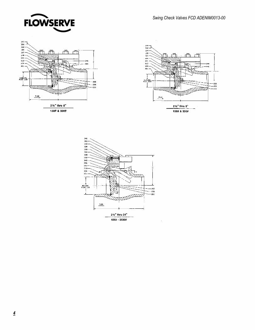
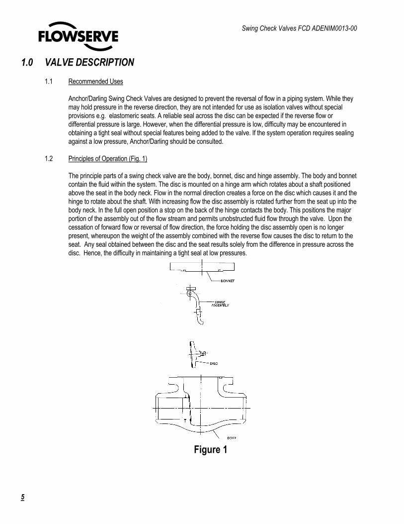
1.2 Principles of Operation (Fig. 1)
The principle parts of a swing check valve are the body, bonnet, disc and hinge assembly. The body and bonnet
contain the fluid within the system. The disc is mounted on a hinge arm which rotates about a shaft positioned
above the seat in the body neck. Flow in the normal direction creates a force on the disc which causes it and the
hinge to rotate about the shaft. With increasing flow the disc assembly is rotated further from the seat up into the
body neck. In the full open position a stop on the back of the hinge contacts the body. This positions the major
portion of the assembly out of the flow stream and permits unobstructed fluid flow through the valve. Upon the
cessation of forward flow or reversal of flow direction, the force holding the disc assembly open is no longer
present, whereupon the weight of the assembly combined with the reverse flow causes the disc to return to the
seat. Any seal obtained between the disc and the seat results solely from the difference in pressure across the
disc. Hence, the difficulty in maintaining a tight seal at low pressures.
Figure 1

Swing Check Valves FCD ADENIM0013-00
6
1.0 VALVE DESCRIPTION (Continued)
1.3 Design Features
1.3.1 Bonnet Seals
Anchor/Darling swing check valves are supplied with two basic types of body/bonnet closures; bolted
bonnet or pressure seal. The bolted bonnet closure (Fig. 2) is a bolted flange tongue and groove joint
with a gasket generally comprised of spiral-wound stainless steel and asbestos filler. The seal
depends upon the bolt preload to maintain sufficient compressive force on the gasket.
Pressure seal type closures (Fig. 3) utilize a tapered soft metal ring gasket for sealing. The gasket is
contained within the body neck bore by a retaining ring. The tapered inner surface of the gasket bears
against a mating angular surface on the valve bonnet. Under internal pressure, the bonnet is forced
against the pressure seal gasket, wedging it against the body neck wall. A slight interference angle
produces a line contact and high sealing pressure. The greater the valve pressure, the tighter the
metal-to-metal seal. No bolting is required to maintain the seal although the bonnet is initially drawn
into contact with the pressure seal by cap screws.
Figure 2 Figure 3
Swing Check Valves FCD ADENIM0013-00
7
1.0 VALVE DESCRIPTION (Continued)
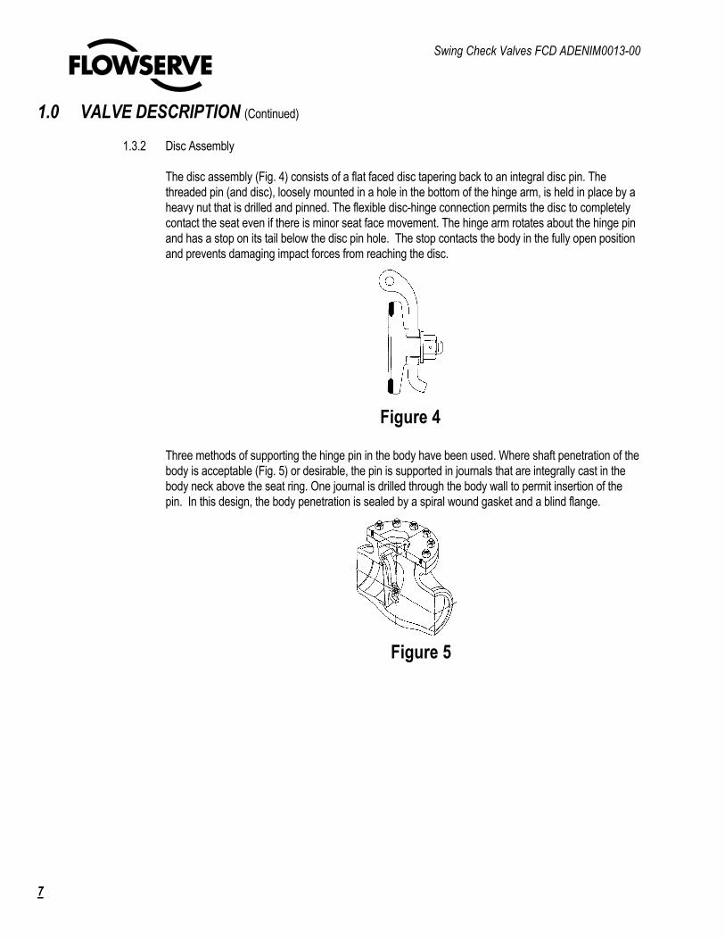
1.3.2 Disc Assembly
The disc assembly (Fig. 4) consists of a flat faced disc tapering back to an integral disc pin. The
threaded pin (and disc), loosely mounted in a hole in the bottom of the hinge arm, is held in place by a
heavy nut that is drilled and pinned. The flexible disc-hinge connection permits the disc to completely
contact the seat even if there is minor seat face movement. The hinge arm rotates about the hinge pin
and has a stop on its tail below the disc pin hole. The stop contacts the body in the fully open position
and prevents damaging impact forces from reaching the disc.
Three methods of supporting the hinge pin in the body have been used. Where shaft penetration of the
body is acceptable (Fig. 5) or desirable, the pin is supported in journals that are integrally cast in the
body neck above the seat ring. One journal is drilled through the body wall to permit insertion of the
pin. In this design, the body penetration is sealed by a spiral wound gasket and a blind flange.
Figure 4
Figure 5
Swing Check Valves FCD ADENIM0013-00
8
1.0 VALVE DESCRIPTION (Continued)
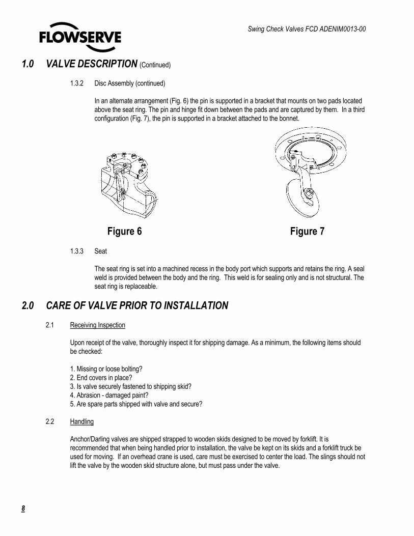
1.3.2 Disc Assembly (continued)
In an alternate arrangement (Fig. 6) the pin is supported in a bracket that mounts on two pads located
above the seat ring. The pin and hinge fit down between the pads and are captured by them. In a third
configuration (Fig. 7), the pin is supported in a bracket attached to the bonnet.
1.3.3 Seat
The seat ring is set into a machined recess in the body port which supports and retains the ring. A seal
weld is provided between the body and the ring. This weld is for sealing only and is not structural. The
seat ring is replaceable.
2.0 CARE OF VALVE PRIOR TO INSTALLATION
2.1 Receiving Inspection
Upon receipt of the valve, thoroughly inspect it for shipping damage. As a minimum, the following items should
be checked:
1. Missing or loose bolting?
2. End covers in place?
3. Is valve securely fastened to shipping skid?
4. Abrasion - damaged paint?
5. Are spare parts shipped with valve and secure?
2.2 Handling
Anchor/Darling valves are shipped strapped to wooden skids designed to be moved by forklift. It is
recommended that when being handled prior to installation, the valve be kept on its skids and a forklift truck be
used for moving. If an overhead crane is used, care must be exercised to center the load. The slings should not
lift the valve by the wooden skid structure alone, but must pass under the valve.
Figure 6 Figure 7

Swing Check Valves FCD ADENIM0013-00
9
2.0 CARE OF VALVE PRIOR TO INSTALLATION (Continued)
2.3 Storage
Store valves on their shipping skids in a clean and dry area protected from the weather.
3.0 INSTALLATION INSTRUCTIONS
3.1 Rigging
When lifting the valve for installation in the line, it is important that slings of adequate size be used. The capacity
of the sling must exceed the weight of the valve. Slings should pass under the valve body. Block carefully to
prevent damage or abrasion of component parts and finishes.
3.2 Cleaning
Prior to installation remove the valve end covers and inspect for cleanliness. If any sign of foreign matter is
observed
in the valve internals, open the valve and place it on its side and flush thoroughly with water. Steam or air may
be used if water is not available but exercise caution that the high velocity does not drive debris into clearance
spaces.
3.3 Installing Valve In-line
The pipe must be properly supported and aligned with the valve. Seat leakage in valves is frequently caused by
seat misalignment resulting from excessive end movements introduced in the cold springing of the connecting
pipe. Check valves, with their automatic operation, must be installed with the flow in the proper direction. The
arrow on body should point in the normal flow direction, I.e., the direction in which flow is desired. Swing check
valves can be installed in both horizontal and vertical lines. However, in vertical lines the normal flow must be
upward and the checked flow downward. In all installations the valve must be oriented such that the hinge pin is
horizontal.
4.0 VALVE MAINTENANCE
Anchor/Darling Valves are designed to be essentially maintenance free pieces of equipment. When used in the proper
application and operated correctly they will provide reliable operation for many years. Some other maintenance
recommendations are included in the following sections for information.

Swing Check Valves FCD ADENIM0013-00
10
4.0 VALVE MAINTENANCE (Continued)
4.1 Inspection
The most important aspect of valve maintenance is periodic inspection. The early detection of a malfunction
can, in many cases, prevent a minor defect from becoming a major problem. It is very important that leakage
from any of the major seals (disc/seat, body-bonnet) be addressed immediately. The smallest weepage can
quickly become a major problem if it is not treated promptly. Some other areas that should be included in a
periodic inspection program are:
1. Cleaning: Pressure Seal Area and Body-Bonnet Studs
2. Bolting: Body-Bonnet and Hinge Pin Cover
4.2 Cleaning
The frequency and extent of cleaning will depend on the valves' location and service conditions. Do not allow
water or dirt to collect in the body neck bore area above the pressure seal of pressure seal valves. The build up
of corrosion or extraneous material may interfere with removal of the bonnet. For the same reason, excessive
rust should not be allowed to build-up on the body-bonnet bolting of bolted bonnet valves.
4.3 Bolt Torquing
At regular intervals, not more than six months, check the tightness of all bolting. Bolted bonnet valves should
have the body-bonnet bolting torqued to the valves shown in Table 2.
4.4 Refinishing Sealing Surfaces
Minor discontinuities in both the disc and seat sealing surfaces, which may cause leakage, can, in many cases,
be removed by lapping. Major defects such as cracks or deep gouges will generally require replacement of the
part.
(NOTE: Lapping is a polishing process in which a sealing surface is ground with an abrasive held in place by a
special fixture. The abrasive is commonly found in paste form or bonded to a paper backing. Detailed
instructions on the use of lapping abrasives and fixtures, normally supplied with such equipment, should be
adhered to). In addition to the following lapping materials manufacturers' recommendations, the following
precaution should be observed. Anchor/Darling swing check valves are supplied with a crowned sealing
surface on the seat in order to provide precise seat width and tight sealing. Lapping of the seat will cause the
sealing band width to be significantly increased.
Subsequent to all seat refinishing operations, the seat width must be checked against dimensions supplied in
Table 1 and reduced if necessary. Failure to do so may create leakage problems, particularly at low pressures.

Swing Check Valves FCD ADENIM0013-00
11
4.0 VALVE MAINTENANCE (Continued)
4.4 Refinishing Sealing Surfaces (Continued)
5.0 DISASSEMBLY
By carefully following these instructions, any Anchor/Darling valve can be easily disassembled and reassembled. If
problems are encountered with equipment, Anchor/Darling Field Service should be contacted. The use of improper tools
or methods may cause severe damage to the valve and may void the warranty. Prior to attempting disassembly of a
particular valve, refer to the specific assembly drawing for the valve.
5.1 Flanged Bonnet Valves
5.1.1 Bonnet (Fig. 8)
Remove the nuts (230) from the bonnet studs (200). Although it is not imperative, it may be helpful to
loosen the nuts in a criss-cross pattern (Fig. 18). With the nuts removed, the bonnet can be lifted off
the body. Tapped holes are provided in the top of larger bonnets to accept eyebolts. The bonnets on
these valves are most easily raised using slings attached to the eyebolts. (NOTE: Some older
Anchor/Darling swing check valves were designed with the disc assembly attached to the bonnet (See
5.1.2.2). With this design care should be taken in raising the bonnet so that the disc is not damaged.)
With the bonnet removed, the old gasket (100) should be lifted out of its groove. Be careful not to
damage the gasket sealing surface.
F Valve Size
600# 900# 1500#
2-1/2 .090 .090 .125
3 .090 .090 .125
4 .090 .090 .156
6 .125 .125 .187
8 .125 .156 .218
10 .156 .156 .250
12 .156 .187 .250
14 .156 .187 .250
16 .187 .218 .281
18 .187 .218 .312
20 .187 .218 .312
22 .187 .218 .312
24 .187 .218 .312
Swing Check For 150# and 300#
F = 3/32”
Hardfacing
Seat Ring
TABLE 1
NOMINAL SEAT WIDTH

Swing Check Valves FCD ADENIM0013-00
12
5.0 DISASSEMBLY (Continued)
FIGURE 8
Swing Check Valves FCD ADENIM0013-00
13
5.0 DISASSEMBLY (Continued)
5.1.2 Disc Assembly
Three methods of supporting the disc assembly in the body have been used by Anchor/Darling.
A. Hinge rotates on pin inserted through body wall (Fig. 9).
B. Hinge rotates on pin mounted in bracket hung from bonnet (Fig. 14).
C. Hinge rotates on pin supported in bracket mounted on pads above seat ring (Fig 15).
(Fig. 15) is the design currently supplied by Anchor/Darling.
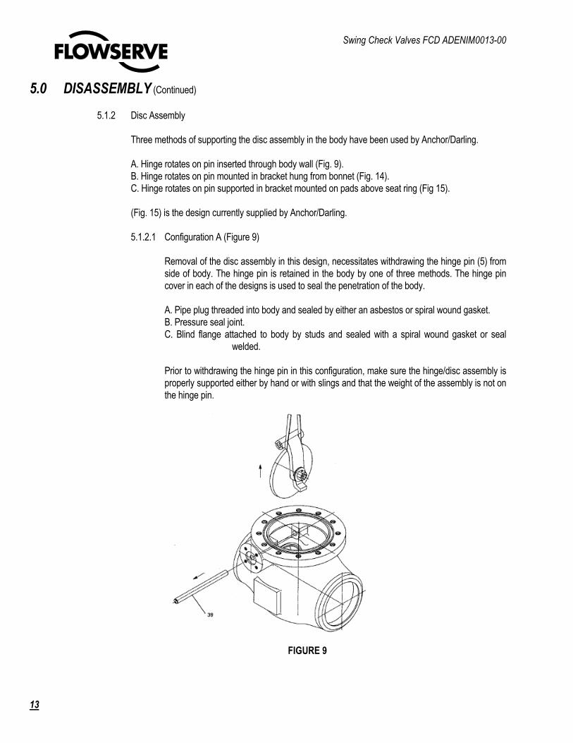
5.1.2.1 Configuration A (Figure 9)
Removal of the disc assembly in this design, necessitates withdrawing the hinge pin (5) from
side of body. The hinge pin is retained in the body by one of three methods. The hinge pin
cover in each of the designs is used to seal the penetration of the body.
A. Pipe plug threaded into body and sealed by either an asbestos or spiral wound gasket.
B. Pressure seal joint.
C. Blind flange attached to body by studs and sealed with a spiral wound gasket or seal
welded.
Prior to withdrawing the hinge pin in this configuration, make sure the hinge/disc assembly is
properly supported either by hand or with slings and that the weight of the assembly is not on
the hinge pin.
FIGURE 9
Swing Check Valves FCD ADENIM0013-00
14
5.0 DISASSEMBLY (Continued)
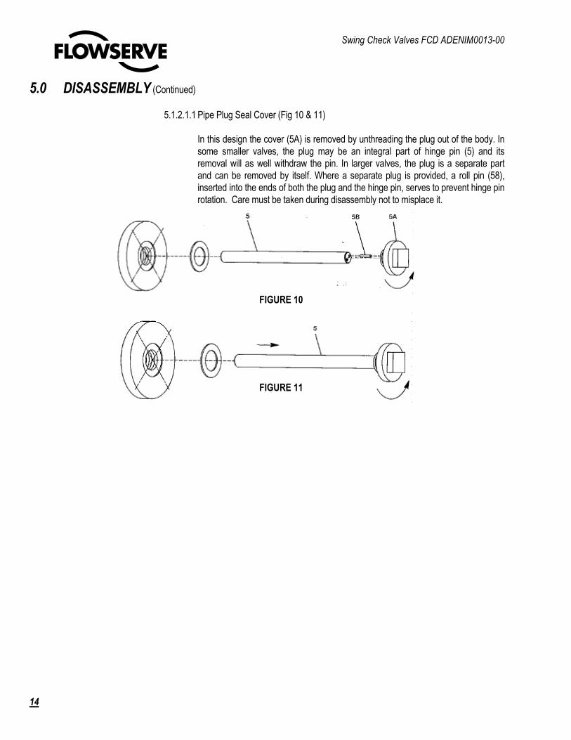
5.1.2.1.1 Pipe Plug Seal Cover (Fig 10 & 11)
In this design the cover (5A) is removed by unthreading the plug out of the body. In
some smaller valves, the plug may be an integral part of hinge pin (5) and its
removal will as well withdraw the pin. In larger valves, the plug is a separate part
and can be removed by itself. Where a separate plug is provided, a roll pin (58),
inserted into the ends of both the plug and the hinge pin, serves to prevent hinge pin
rotation. Care must be taken during disassembly not to misplace it.
FIGURE 10
FIGURE 11

Swing Check Valves FCD ADENIM0013-00
15
5.0 DISASSEMBLY (Continued)
5.1.2.1.2 Pressure Seal Cover (Fig 12)
In this design, the hinge pin cover (10) holds a metal gasket (6A) against the hinge
pin bonnet (2A) by studs threaded into the body. As with the pipe plug design, in
small valves the bonnet may be an integral part of the hinge pin (5). To remove the
cover, unthread the nuts (8A) off the studs (8). The cover can then be removed. The
gasket and bonnet are most easily removed as one unit. The bonnet is provided
with a tapped hole in the end. If the hinge pin cover has not been disassembled for
a long period of time the gasket and bonnet may stick in the body. Prior to
attempting removal, lubricate the area well with penetrating oil. Although the hole in
the bonnet is intended for an eye bolt, if the bonnet is extremely tight a slide
hammer may be attached to the bonnet to free it. In withdrawing the bonnet/gasket it
is important to pull on the assembly squarely. If the bonnet/gasket becomes cocked,
removal can be quite difficult. Once the bonnet and gasket are removed, the hinge
pin can be withdrawn.
5.1.2.1.3 Blind Flange Cover (Fig 13)
In this design the cover (037) is held against a spiral wound gasket (101) by nuts on
studs threaded into the body. The cover can be removed after the cover nuts (229)
are unthreaded off the studs. A roll pin (263) inserted into the cover and the end of
the hinge pin (039) is used to prevent rotation of the hinge pin. Care must be taken
during disassembly to avoid misplacing it. With the cover off, the hinge pin can be
withdrawn. A tapped hole is provided in the end of the hinge pin to facilitate
withdrawal.
FIGURE 12
FIGURE 13
Swing Check Valves FCD ADENIM0013-00
16
5.0 DISASSEMBLY (Continued)
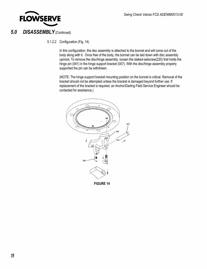
5.1.2.2 Configuration (Fig. 14)
In this configuration, the disc assembly is attached to the bonnet and will come out of the
body along with it. Once free of the body, the bonnet can be laid down with disc assembly
upmost. To remove the disc/hinge assembly, loosen the staked-setscrew(220) that holds the
hinge pin (041) in the hinge support bracket (007). With the disc/hinge assembly properly
supported the pin can be withdrawn.
(NOTE: The hinge support bracket mounting position on the bonnet is critical. Removal of the
bracket should not be attempted unless the bracket is damaged beyond further use. If
replacement of the bracket is required, an Anchor/Darling Field Service Engineer should be
contacted for assistance.)
FIGURE 14

Swing Check Valves FCD ADENIM0013-00
17
5.0 DISASSEMBLY (Continued)
5.1.2.3 Configuration C (Fig. 15)
In this configuration, the disc assembly is mounted on pads in the body and held in place by
hex head bolts. To remove the assembly, bend back the tabs on the tab lock washers (251)
and unthread the hex head bolts (289). The hinge support (007) can now be raised. The
hinge pin (041) is held in place by two retaining rings (245). Once the disc assembly is safely
supported, the retaining rings can be removed and the pin withdrawn. A pin (257) is used to
prevent rotation of pin in the bracket. Care should be taken not to misplace it.
FIGURE 15
Swing Check Valves FCD ADENIM0013-00
18
5.0 DISASSEMBLY (Continued)
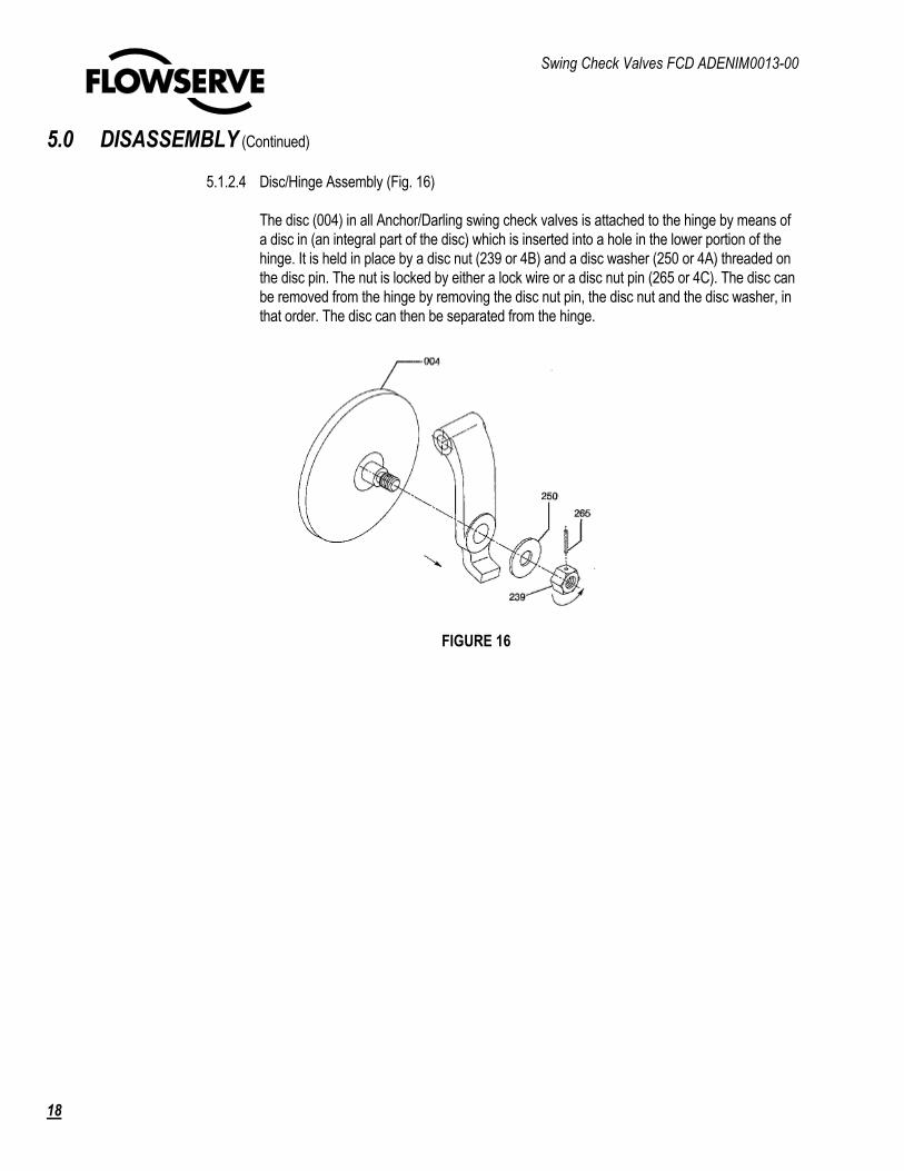
5.1.2.4 Disc/Hinge Assembly (Fig. 16)
The disc (004) in all Anchor/Darling swing check valves is attached to the hinge by means of
a disc in (an integral part of the disc) which is inserted into a hole in the lower portion of the
hinge. It is held in place by a disc nut (239 or 4B) and a disc washer (250 or 4A) threaded on
the disc pin. The nut is locked by either a lock wire or a disc nut pin (265 or 4C). The disc can
be removed from the hinge by removing the disc nut pin, the disc nut and the disc washer, in
that order. The disc can then be separated from the hinge.
FIGURE 16

Swing Check Valves FCD ADENIM0013-00
19
5.0 DISASSEMBLY (Continued)
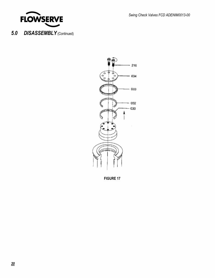
5.2 Pressure Seal Bonnet Valves (Fig 17)
5.2.1 Bonnet
A. Unbolt the capscrews (bonnet) (216) and remove the bonnet retainer (034). Set aside for use later.
B. Tap Ule 150nnet sharply to break the seal between it and the pressure seal gasket (030).The
bonnet will drop downward against its stop, uncovering the retaining ring (gasket) (033).
C. The retaining ring (gasket) (033) is comprised of four segments, one of which has a small drilled
hole. Remove this piece first. The groove in the top of the retaining ring gasket permits the use of a
pry bar or screwdriver in removing the segments. In some cases, it may be necessary to loosen the
segments by tapping with a hammer or bar.
D. The bonnet is now ready for removal from the body. The tight clearances between the body bonnet
and gasket, necessary for a reliable seal, require that the' bonnet be withdrawn squarely 'from the neck
bore. The slightest cocking of the bonnet during withdrawal can cause it to bind. Therefore, it is
recommended prior to removal, that the squareness of bonnet and gasket with respect to the body be
checked. This is most easily accomplished by measuring the distance between the top of the gasket
and top of the body neck. If the gasket is not square, it should be tapped with a brass rod until it is.
With large bonnets i(is a good idea as well to periodically check the squareness of bonnet as it 'is
being withdrawn. Binding any time during withdrawal indicates the bonnet has cocked. Further efforts
to force the, bonnet will generally make the situation worse. At the first sign of binding, stop and check
the squareness of the bonnet.
E. The preferred method of lifting the bonnet is by using slings attached to an eyebolt threaded into the
tapped hole in its center.
F. Following the above procedure will, in most cases, result in removal of the bonnet with little difficulty.
However, certain circumstances, such as installation of the valve in other than a horizontal orientation,
may cause complications. If greater difficulty is encountered, an Anchor/Darling service engineer
should be consulted. Excessive force which may damage critical surfaces should be avoided.
G. It is not normally recommended that the pressure seal gasket be reused. However, if a spare
gasket is not available, mark the gasket, bonnet and body prior to removal so that the gasket may be
reinstalled in its original orientation.
5.2.2 Disc Assembly
Anchor/Darling pressure seal swing check valves have been supplied with disc support configurations
as described in sections 5.1.2.1 and 5.1.2.3. Refer to these sections and section 5.1.2.4 for
disassembly procedures.
Swing Check Valves FCD ADENIM0013-00
20
5.0 DISASSEMBLY (Continued)
FIGURE 17
Swing Check Valves FCD ADENIM0013-00
21
6.0 ASSEMBLY
Before starting the reassembly of the valve, all parts should be thoroughly cleaned and inspected. All foreign material
should be removed from any area of the valve. However, there are certain critical areas that must be free of dirt, weld
spatter, filings, etc. These include the following:
1. Disc and seat sealing surfaces
2. Bonnet 00 (on pressure seal valves)
3. Body neck 10 (on pressure seal valves)
4. Gasket tongue (on flanged bonnets)
5. Gasket groove (on flanged bodies)
6. Bonnet studs and nuts
7. Hinge pin
8. Hinge pin cover gasket groove in body
9. Hinge pin cover
10. Pressure seal gasket
The above areas must also be free of any nicks, scratches, gouges, etc. Any damage in these areas must be repaired.
Any questions about the acceptability of any surface condition should be discussed with a service engineer prior to using
the part.
6.1 Flanged Bonnet Valves
6.1.1 Disc Assembly
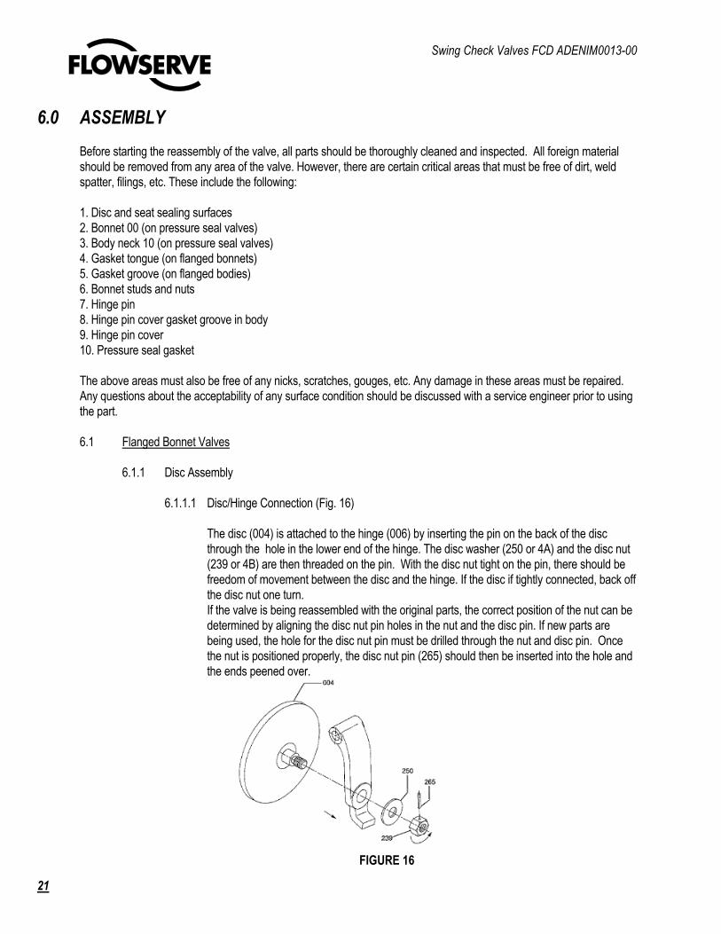
6.1.1.1 Disc/Hinge Connection (Fig. 16)
The disc (004) is attached to the hinge (006) by inserting the pin on the back of the disc
through the hole in the lower end of the hinge. The disc washer (250 or 4A) and the disc nut
(239 or 4B) are then threaded on the pin. With the disc nut tight on the pin, there should be
freedom of movement between the disc and the hinge. If the disc if tightly connected, back off
the disc nut one turn.
If the valve is being reassembled with the original parts, the correct position of the nut can be
determined by aligning the disc nut pin holes in the nut and the disc pin. If new parts are
being used, the hole for the disc nut pin must be drilled through the nut and disc pin. Once
the nut is positioned properly, the disc nut pin (265) should then be inserted into the hole and
the ends peened over.
FIGURE 16
Swing Check Valves FCD ADENIM0013-00
22
6.0 ASSEMBLY (Continued)
6.1.1.2 Hinge Mounting
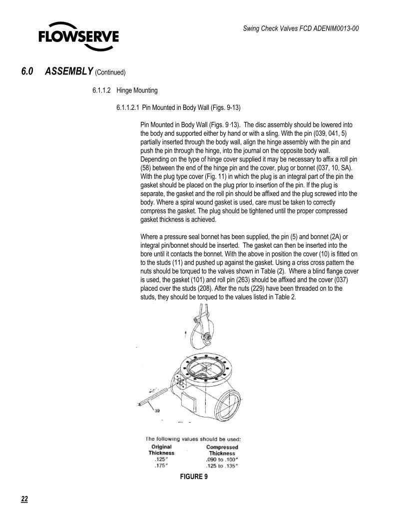
6.1.1.2.1 Pin Mounted in Body Wall (Figs. 9-13)
Pin Mounted in Body Wall (Figs. 9�13). The disc assembly should be lowered into
the body and supported either by hand or with a sling. With the pin (039, 041, 5)
partially inserted through the body wall, align the hinge assembly with the pin and
push the pin through the hinge, into the journal on the opposite body wall.
Depending on the type of hinge cover supplied it may be necessary to affix a roll pin
(58) between the end of the hinge pin and the cover, plug or bonnet (037, 10, SA).
With the plug type cover (Fig. 11) in which the plug is an integral part of the pin the
gasket should be placed on the plug prior to insertion of the pin. If the plug is
separate, the gasket and the roll pin should be affixed and the plug screwed into the
body. Where a spiral wound gasket is used, care must be taken to correctly
compress the gasket. The plug should be tightened until the proper compressed
gasket thickness is achieved.
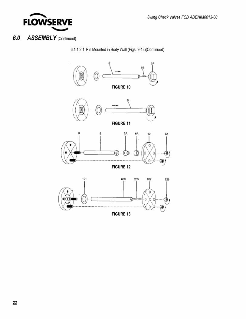
Where a pressure seal bonnet has been supplied, the pin (5) and bonnet (2A) or
integral pin/bonnet should be inserted. The gasket can then be inserted into the
bore until it contacts the bonnet. With the above in position the cover (10) is fitted on
to the studs (11) and pushed up against the gasket. Using a criss cross pattern the
nuts should be torqued to the valves shown in Table (2). Where a blind flange cover
is used, the gasket (101) and roll pin (263) should be affixed and the cover (037)
placed over the studs (208). After the nuts (229) have been threaded on to the
studs, they should be torqued to the values listed in Table 2.
FIGURE 9
Swing Check Valves FCD ADENIM0013-00
23
6.0 ASSEMBLY (Continued)
6.1.1.2.1 Pin Mounted in Body Wall (Figs. 9-13)(Continued)
FIGURE 10
FIGURE 11
FIGURE 12
FIGURE 13
Swing Check Valves FCD ADENIM0013-00
24
6.0 ASSEMBLY (Continued)
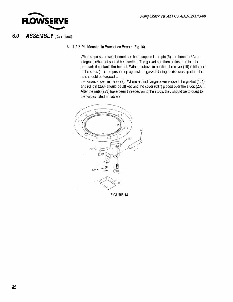
6.1.1.2.2 Pin Mounted in Bracket on Bonnet (Fig 14)
Where a pressure seal bonnet has been supplied, the pin (5) and bonnet (2A) or
integral pin/bonnet should be inserted. The gasket can then be inserted into the
bore until it contacts the bonnet. With the above in position the cover (10) is fitted on
to the studs (11) and pushed up against the gasket. Using a criss cross pattern the
nuts should be torqued to
the vaives shown in Table (2). Where a blind flange cover is used, the gasket (101)
and roll pin (263) should be affixed and the cover (037) placed over the studs (208).
After the nuts (229) have been threaded on to the studs, they should be torqued to
the values listed in Table 2.
FIGURE 14
Swing Check Valves FCD ADENIM0013-00
25
6.0 ASSEMBLY (Continued)
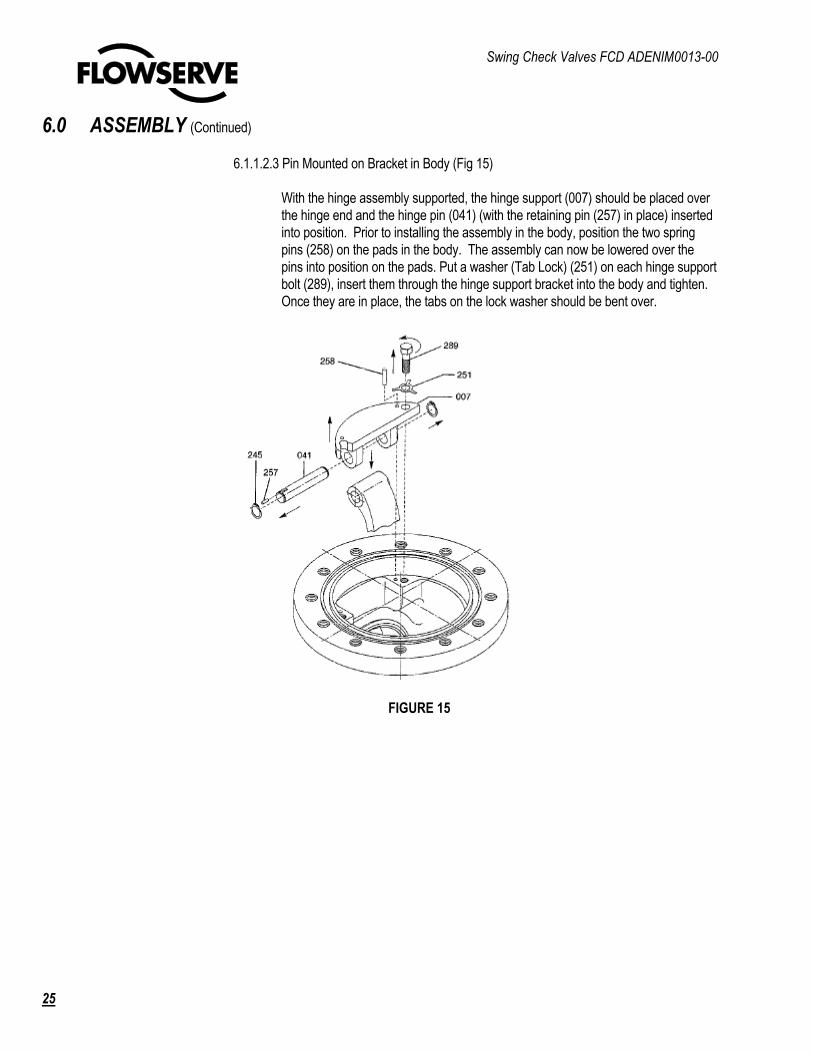
6.1.1.2.3 Pin Mounted on Bracket in Body (Fig 15)
With the hinge assembly supported, the hinge support (007) should be placed over
the hinge end and the hinge pin (041) (with the retaining pin (257) in place) inserted
into position. Prior to installing the assembly in the body, position the two spring
pins (258) on the pads in the body. The assembly can now be lowered over the
pins into position on the pads. Put a washer (Tab Lock) (251) on each hinge support
bolt (289), insert them through the hinge support bracket into the body and tighten.
Once they are in place, the tabs on the lock washer should be bent over.
FIGURE 15
Swing Check Valves FCD ADENIM0013-00
26
6.0 ASSEMBLY (Continued)
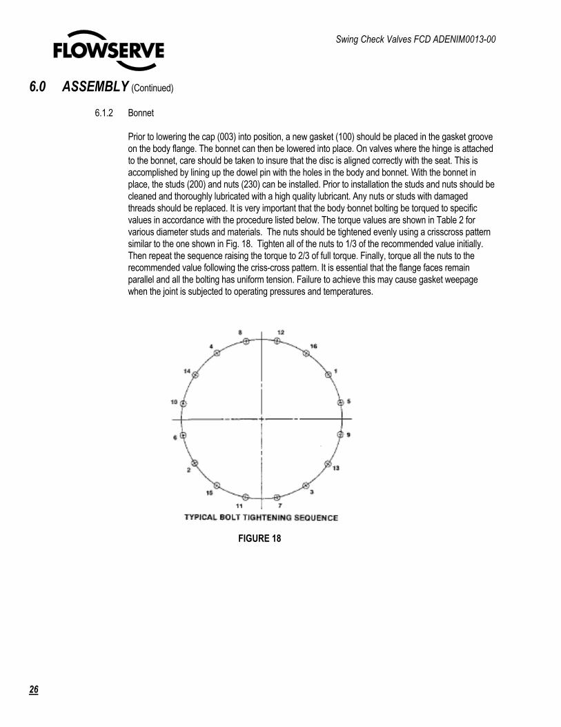
6.1.2 Bonnet
Prior to lowering the cap (003) into position, a new gasket (100) should be placed in the gasket groove
on the body flange. The bonnet can then be lowered into place. On valves where the hinge is attached
to the bonnet, care should be taken to insure that the disc is aligned correctly with the seat. This is
accomplished by lining up the dowel pin with the holes in the body and bonnet. With the bonnet in
place, the studs (200) and nuts (230) can be installed. Prior to installation the studs and nuts should be
cleaned and thoroughly lubricated with a high quality lubricant. Any nuts or studs with damaged
threads should be replaced. It is very important that the body�bonnet bolting be torqued to specific
values in accordance with the procedure listed below. The torque values are shown in Table 2 for
various diameter studs and materials. The nuts should be tightened evenly using a crisscross pattern
similar to the one shown in Fig. 18. Tighten all of the nuts to 1/3 of the recommended value initially.
Then repeat the sequence raising the torque to 2/3 of full torque. Finally, torque all the nuts to the
recommended value following the criss-cross pattern. It is essential that the flange faces remain
parallel and all the bolting has uniform tension. Failure to achieve this may cause gasket weepage
when the joint is subjected to operating pressures and temperatures.
FIGURE 18
Swing Check Valves FCD ADENIM0013-00
27
6.0 ASSEMBLY (Continued)
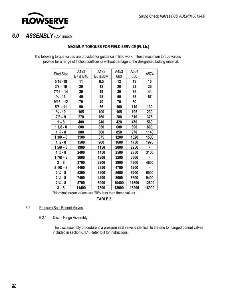
MAXIMUM TORQUES FOR FIELD SERVICE (Ft. Lb.)
The following torque values are provided for guidance in filed work. These maximum torque values
provide for a range of friction coefficients without damage to the designated bolting material.
Stud Size A193
B7 & B16
A193
B8 &B8M
A453
660
A564
630 A574
5/16 -18 11 6.5 12 13 15
3/8 – 16 20 12 20 23 26
7/16 – 14 30 19 30 36 44
½ - 13 45 28 50 55 67
9/16 – 12 70 40 70 80 -
5/8 – 11 90 56 100 110 130
¾ - 10 165 100 165 195 230
7/8 – 9 270 160 280 310 375
1 – 8 400 240 420 470 560
1 1/8 - 8 600 350 600 690 800
1 ¼ - 8 800 500 850 970 1140
1 3/8 – 8 1100 675 1200 1320 1500
1 ½ - 8 1500 900 1600 1750 1970
1 5/8 – 8 1900 1150 2000 2250 -
1 ¾ - 8 2400 1450 2500 2850 3100
1 7/8 – 8 3000 1800 3200 3500 -
2 – 8 3700 2200 3900 4300 4600
2 1/8 – 8 4400 2650 4700 5200 -
2 ¼ - 8 5300 3200 5600 6200 6900
2 ½ - 8 7400 4400 8000 8600 9400
2 ¾ - 8 8700 5900 10400 11600 12800
3 – 8 11400 7800 13000 15200 16900
*Nominal torque values are 20% less than these values.
6.2 Pressure Seal Bonnet Valves
6.2.1 Disc – Hinge Assembly
The disc assembly procedure in a pressure seal valve is identical to the one for flanged bonnet valves
included in section 6.1.1. Refer to it for instructions.
TABLE 2

Swing Check Valves FCD ADENIM0013-00
28
6.0 ASSEMBLY (Continued)
6.2.2 Bonnet
Once the hinge - disc assembly is in place, the bonnet (002) can be inserted into the neck. Care must
be taken in lowering the bonnet. It is again very important to keep the bonnet from cocking, as it is
lowered into the body. If it does bind, the bonnet must be straightened before insertion can continue.
Measuring from the bonnet bolting surface to the top of the body is the simplest way to detect cocking.
With the bonnet resting on the counterbore in the neck, a new gasket (030) and the spacer ring (032)
can be inserted. In that the gasket may also cock, it must be inserted with care. Once these are in
place, the four-piece gasket retainer (033) can be put into place. It is important to remember that the
piece with the drilled hole must be positioned last. If the valve is installed in other than a horizontal
position, it may be necessary to orient or hold the retainer such that the pieces stay in place until the
bonnet is moved into its raised position. Prior to installing the bonnet retainer, the pipe plug (336)
should be removed. A threaded rod, long enough to extend from the top of the bonnet above the body
neck should be inserted into the tapped hole in the center of the bonnet. The bonnet retainer (034)
can now be lowered over the top of the rod and set into position. Using the threaded rod the bonnet
can be raised into its position and the bonnet capscrews (216) inserted through the retainer and
threaded into their holes in the bonnet. By turning each capscrew a couple of turns, proceeding to the
adjacent capscrew, turning it and then repeating this around the bolt circle, the bonnet will be raised
squarely until it is firmly in contact with the gasket. Note that while the capscrews need not be torqued
to a specific value to maintain a tight seal at system pressures, they should be tightened with wrench
to insure good gasket-body-bonnet seal contact before the full pressure is reached.
FIGURE 17

United States Flowserve Corporation Flow Control Division 1900 S. Saunders Street Raleigh, NC 27603 Phone: (919) 832-0525 Fax: (919) 831-3369
Flowserve Corporation has established industry leadership in the design and manufacture of its products. When properly selected, this Flowserve product is designed to perform its intended function safely during its useful life. However, the purchaser or user of Flowserve products should be aware that Flowserve products might be used in numerous applications under a wide variety of industrial service conditions. Although Flowserve can provide general guidelines, it cannot provide specific data and warnings for all possible applications. The purchaser/user must therefore assume the ultimate responsibility for the proper sizing and selection, installation, operation, and maintenance of Flowserve products. The purchaser/user should read and understand the (INSERT OFFICIAL USER INSTRUCTION TITLE) instructions included with the product, and train its employees and contractors in the safe use of Flowserve products in connection with the specific application. While the information and specifications contained in this literature are believed to be accurate, they are supplied for informative purposes only and should not be considered certified or as a guarantee of satisfactory results by reliance thereon. Nothing contained herein is to be construed as a warranty or guarantee, express or implied, regarding any matter with respect to this product. Because Flowserve is continually improving and upgrading its product design, the specifications, dimensions and information contained herein are subject to change without notice. Should any question arise concerning these provisions, the purchaser/user should contact Flowserve Corporation at any one of its worldwide operations or offices. © 2006 Flowserve Corporation, Irving, Texas USA. Flowserve is a registered trademark of Flowserve Corporation
FDC ADENIM0013-00 Printed in USA.
To find your local Flowserve representative: For more information about Flowserve Corporation, visit
www.flowserve.com or call USA 1 800 225 6989