switch mode, manual automatic, lead acid …...owner's manual please read this manual before...
TRANSCRIPT

OWNER'S MANUALPlease read this manual BEFORE operating your battery charger
Switch Mode, Automatic, Lead Acid Battery Charger
MODELS:SEC-1280ULSEC-2440UL

2 | SAMLEX AMERICA INC.
OWNER'S MANUAL: Battery Chargers | Index
SECTION 1: Important Safety Precautions ......................................3
SECTION 2: Description & Features ................................................5
SECTION 3: Layout .........................................................................6
SECTION 4: Principle of Operation .................................................7
SECTION 5: Protections ................................................................14
SECTION 6: Installation ................................................................16
SECTION 7: Preparing the Charger for Operation ........................18
SECTION 8: Operation ................................................................ 24
SECTION 9: Troubleshooting ........................................................26
SECTION 10: Internal Fuse Ratings .................................................28
SECTION 11: Specifications ............................................................28
SECTION 12: Warranty ...................................................................30
Disclaimer of LiabilityUNLESS SPECIFICALLY AGREED TO IN WRITING, SAMLEX AMERICA, INC.:
1. MAKES NO WARRANTY AS TO THE ACCURACY, SUFFICIENCY OR SUITABILITY OF ANY TECHNICAL OR OTHER INFORMATION PROVIDED IN ITS MANUALS OR OTHER DOCUMENTATION.
2. ASSUMES NO RESPONSIBILITY OR LIABILITY FOR LOSSES, DAMAGES, COSTS OR EXPENSES, WHETHER SPECIAL, DIRECT, INDIRECT, CONSEQUENTIAL OR INCIDENTAL, WHICH MIGHT ARISE OUT OF THE USE OF SUCH INFORMATION. THE USE OF ANY SUCH INFORMATION WILL BE ENTIRELY AT THE USERS RISK.
Copyright Notice/Notice of CopyrightCopyright © 2016 by Samlex America, Inc. All rights reserved. Permission to copy, distribute and/or modify this document is prohibited without express written permission by Samlex America, Inc.

2 | SAMLEX AMERICA INC. SAMLEX AMERICA INC. | 3
SECTION 1 | Important Safety Precautions
The following safety symbols will be used in this manual to highlight safety and information:
WARNING!
Indicates possibility of physical harm to the user in case of non-compliance.
! CAUTION!
Indicates possibility of damage to the equipment in case of non-compliance.
i
INFO
Indicates useful supplemental information.
Hazardous conditions may result if the charger is not installed or operated correctly. Please read the following instructions to prevent personal injury or damage to the charger.
BATTERY RELATED • Toreducetheriskofbatteryexplosion,followtheseinstructionsandthosemarkedon
the battery.
• Neversmokeorallowanopensparkorflameinthevicinityofthebatteryortheengine.
• ChargeonlyLeadAcidtypeofbatteries(Flooded/AbsorbedGlassMat(AGM)/GelCell).DonotchargeothertypeofbatterieslikeNickelCadmium(NiCad),Nickel-MetalHydride(Ni-MH),Dry-Celletc.Othertypesofbatteriesmightburstcausingpersonalinjury.
• Neverchargeafrozenbattery.
• WorkinginthevicinityofLeadAcidbatteriesisdangerous.Batteriesgenerateex-plosiveHydrogenandOxygengasesduringnormaloperation.Takenecessarysafetyprecautions when installing the charger near a battery or in a battery compartment (Followsafetyinstructionsgivenbythebatterymanufacturer).
• Neverplacethechargerdirectlyaboveorbelowthebatterybeingcharged;gasesorfluidsfromthebatterywillcorrodeanddamagethecharger.Locatethechargerasfaraway from the battery as DC cables permit. Do not install in the same compartment as batteries.
• Usecautiontoreducetheriskofdroppingametaltoolonthebattery.Itcouldsparkorshortcircuitthebatteryorotherelectricalpartsandcouldcauseanexplosion.

4 | SAMLEX AMERICA INC.
SECTION 1 | Important Safety Precautions
• Removemetalitemslikerings,braceletsandwatcheswhenworkingwithbatteries.The batteries can produce a short circuit current high enough to weld a ring or the liketometalandthuscauseasevereburn.
• Ifyouneedtoremoveabattery,alwaysremovethegroundterminalfromthebatteryfirst.Makesurethatalltheaccessoriesareoffsothatyoudonotcauseaspark.
CHARGER RELATED • ThemaximumAhcapacitiesofthebatteriesmustbelimitedasfollows:
- SEC-1280UL: 800Ah
- SEC-2440UL: 400Ah
• Donotoperatethechargerinaclosed-inareaorrestrictventilationinanyway. Installinawellventilated,cool,dryplace.
• Thechargermustnotbeoperatedinadamporwetenvironment.Whenmounting inaboat,makesureitisnotsubjectedtobilgewatersplash.
• Donotblocktheventilationopenings/openingsforthecoolingfan.Thereshould be at least 6 inches clearance all around the unit.
• InstallationandwiringmustcomplywiththelocalandtheNationalElectricalCodes.It is recommended that installation may be carried out by a certified electrician.
• Wronginstallationonaboatmayleadtocorrosionoftheboat.Itisrecommendedthat installation on the boat must be carried out by a boat electrician.
• DisconnecttheACinputpowertothechargerbeforeconnecting/disconnectingthebatteriesorotherDCloadsorwhenworkingonthecharger.
• DisconnecttheACinputpowerbeforechangingthesettingoftheDipSwitches.
• Thechassisofthechargerisconnectedtotheearthgroundpinofthepowercordplug.EnsurethattheearthgroundpinofACreceptaclefeedingthechargeris connected to earth ground.
• Donotuseanadapter.Ifagroundingtypeofreceptacleisnotavailable,donotusethis charger until proper outlet is installed by a qualified electrician.
• Donotoperatethechargerifthepowercordisdamaged.

4 | SAMLEX AMERICA INC. SAMLEX AMERICA INC. | 5
SECTION 2 | Description & Features
SEC-1280UL(for12Vbatteries)andSEC-2440UL(for24Vbatteries)arehighcurrent,3StageChargers(alsocalledIUOU)thatdeliver80Aand40Arespectivelyforalmost75%to80%ofthechargingcycleensuringaveryfast,safeandcompletechargingofLeadAcidbatteries.Thenomenclature“IUOU”isaDINnomenclatureandsignifiesthe3chargingstages–“I”forBulkChargeStage,“UO”Absorption/Over-chargeStageand“U”forFloat/MaintenanceStage(underDINspecification,voltageisdesignated“U”andcurrentisdesignated“I”.Thesubscript“O”in“UO”signifiesover-charge).
FEATURES• State-of-the-artSwitchModeTechnologyforhighefficiency,light-weightandquiet
operation.
• UserconfigurableACinputvoltage–120VACor230VAC,50/60Hz
• AutomaticoperationforalltypesofLeadAcidBatteries-Flooded,AGMorGelCell
• Userselectable2or3-StageautomaticchargingalgorithmwithtimedAbsorptionStageandtemperaturecompensationensuresrapid,safeandfullreturnofcapacityfor stand-alone and loaded batteries.
• Abilitytoreducemaximumchargingcurrenttoapproximately1/2oftheratedcapac-ityduring“HalfPowerMode”.Thisallowssafechargingoflowercapacitybatteries.
• IncludesaBatteryTemperatureSensorallowingtemperaturecompensatedcharging,if required.
• 2banksofbatteriescanbechargedsimultaneouslywithouttheuseofanexternalbatteryisolator.Thechargingcurrentwillbesharedbetweenthetwobanksdepend-ing upon the depth of discharge of the connected batteries.
• VoltmeterandAmmeterformonitoring
• Fancooled-fanON/OFF based on output current.
• Protectionsagainstshortcircuit,overcurrent,reversebatteryconnectionand over-temperature.
• CanbeusedasapowersupplyorasaDCUPS(UninterruptiblePowerSupply) when used in conjunction with a battery.
• OptionalRemoteLEDPanelModel900-RCwith10Metersofwireforremote ON/OFFcontrolandindicationofchargingstatus.
• SafetycertifiedandlistedtoULStandardUL-1564
• EMIcomplianttoFCCPart15(B),ClassA
MAXIMUM AH CAPACITY OF BATTERY TO BE CHARGEDIfthechargersareusedtochargeveryhighcapacitybatteries,theywillbeforcedtosupplytheirmaximumratedchargingcurrentforlongertimethanthedesignedlimitandhence,thecomponentswillbeoverstressedandarelikelytofailprematurely.Topreventprematurefailure,themaximumAhcapacitiesofthebatteriesmustbelimitedas follows:
- SEC-1280UL:800Ah- SEC-2440UL:400Ah
6 | SAMLEX AMERICA INC.
SECTION 3 | Layout
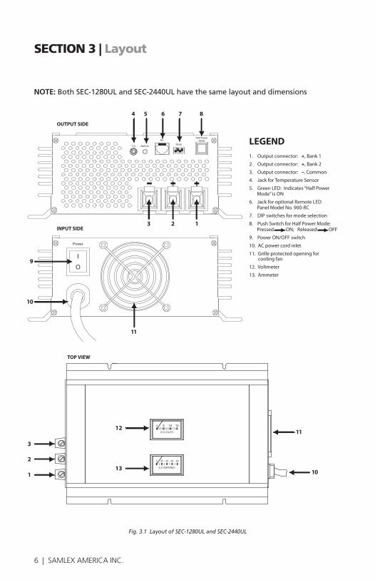
NOTE:BothSEC-1280ULandSEC-2440ULhavethesamelayoutanddimensions
Fig. 3.1 Layout of SEC-1280UL and SEC-2440UL
4 5 6 7 8
3 2 1
9
10
11
OUTPUT SIDE
INPUT SIDE
12
13
LEGEND1. Output connector: +, Bank 1
2. Output connector: +, Bank 2
3. Output connector: –, Common
4. Jack for Temperature Sensor
5. Green LED: Indicates “Half Power Mode” is ON
6. Jack for optional Remote LED Panel Model No. 900-RC
7. DIP switches for mode selection
8. Push Switch for Half Power Mode: Pressed ON; Released OFF
9. Power ON/OFF switch
10. AC power cord inlet
11. Grille protected opening for cooling fan
12. Voltmeter
13. Ammeter
TOP VIEW
3
2
1
11
10
SEC-1280UL & SEC-2440UL

6 | SAMLEX AMERICA INC. SAMLEX AMERICA INC. | 7
SECTION 4 | Principle of Operation
i
INFO
Forcompleteunderstandingofworkingofbatterychargers,understandingofoperationofLeadAcidbatteriesisdesirable.
Fordetailedinformationonconstruction,workingandapplicationofbatteries,pleaserefertoWhitePapersorwww.samlexamerica.com.
BATTERY CHARGER IS A CURRENT LIMITED DC POWER SUPPLYThechargerisacurrentlimitedDCpowersupplythatconverts120/230VAC,50/60HztoregulatedDCvoltagesandlimitsthemaximumoutputcurrentasfollows:
Model No. Current Limit
Constant Voltage at Bulk
Stage “I”
Constant Voltage at Absorption Stage “U0”
Constant Voltage at Float Stage
“U”
SEC-1280UL 80A 13.5VDC14.0VDCor14.4VDC
13.5VDC
SEC-2440UL 40A 27VDC28.0VDCor28.8VDC
27VDC
Thespecifiedoutputvoltageofthechargerduringparticularchargingstageisheldconstanttillthecurrentlimitvalueisreached.WhenthebatteryorDCloadtriestodrawcurrent>thecurrentlimitvalue,thechargerlimitsthecurrenttothecurrentlimitvalueandtheoutputvoltageofthechargerdropsandisnolongerconstant.Whenthechar-gerisconnectedtoabatteryandisincurrentlimitcondition,theterminalvoltageofthechargerwillbeclampedtotheactuallowerintrinsicterminalvoltageofthebattery(assumingthechargerisveryclosetothebatteryandthereisnovoltagedropinthewiresconnectionthechargertothebatteries).
BATTERY IMPEDANCE AND CHARGING CURRENT Theinternalimpedanceofahealthybatteryisverylow-intensofmilliOhms(Theimpedance is higher in discharged condition due to Lead Sulfate formation and reduces whenthebatteryisfullycharged–LeadSulfategetsfullyconvertedtoLeadandLeadDioxide).Averageimpedancemaybeassumedas20milliOhmor0.02Ohm
Whenthechargerisdeliveringaconstantvoltage(isnotincurrentlimitcondition),thecharging current drawn by the battery can be roughly calculated as follows:Charging current = (Charger Voltage - Intrinsic battery voltage) ÷ Internal resistance (0.02 Ohm)
8 | SAMLEX AMERICA INC.
SECTION 4 | Principle of Operation
Forexample,whenSEC-1280ULisintheBulkChargeStage1,itsoutputvoltageissetat13.5VDC.Whenabatterydischargedtosay10.5Vischarged,itwilltrytodrawverylargecurrent=(13.5V-10.5V)÷Internalresistance(0.02Ω)=150A.SEC-1280ULwill,however,limitthiscurrentto80A.
CHARGING STAGESThebatteryischargedin3stages:
• STAGE1-BULKSTAGE(“I”Phase),
• STAGE2-ABSORPTIONSTAGE(“UO”Phase)and
• STAGE3-FLOATSTAGE(“U”Phase)
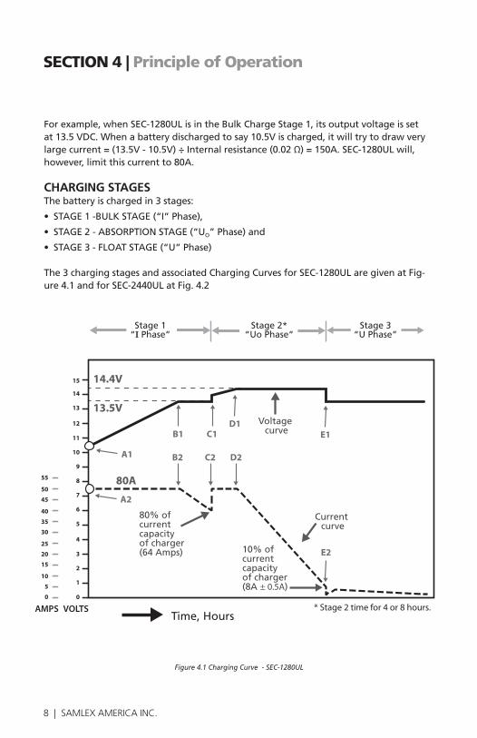
The3chargingstagesandassociatedChargingCurvesforSEC-1280ULaregivenatFig-ure 4.1 and for SEC-2440UL at Fig. 4.2
Figure 4.1 Charging Curve - SEC-1280UL
* Stage 2 time for 4 or 8 hours.
Voltage curve
Current curve
10% ofcurrent capacityof charger(8A ± 0.5A)
80% of current capacityof charger(64 Amps)
Time, Hours
14.4V
13.5V
15
14
13
12
11
10
9
8
7
6
5
4
3
2
1
0
55
50
45
40
35
30
25
20
15
10
5
0
AMPS VOLTS
Fig xxx - SEC-1250UL Charging Curves (Absorption 14.4V, Float 13.5V)
80A
Stage 1“I Phase”
Stage 2*“Uo Phase”
Stage 3“U Phase”
B1 C1D1
E1
B2 C2 D2
E2
A1
A2
8 | SAMLEX AMERICA INC. SAMLEX AMERICA INC. | 9
SECTION 4 | Principle of Operation
Voltage curve
28.8V
27V
30
28
26
24
22
20
18
16
14
12
10
8
6
4
2
0
27.5
25.0
22.5
20.0
17.5
15.0
12.5
10.0
7.5
5.0
2.5
0
Fig xxx - SEC-2425UL Charging Curves (Absorption 28.8V, Float 27V)
B1 C1D1
E1
B2 C2 D2
E2
40A
A1
A2
Stage 1“I Phase”
Stage 2*“Uo Phase”
Stage 3“U Phase”
* Stage 2 time for 4 or 8 hours.
Voltage curve
Current curve
80% ofcurrent capacityof charger(32 amps) 10% of
current capacityof charger(4A ± 0,5A)
Time, HoursAMPS VOLTS
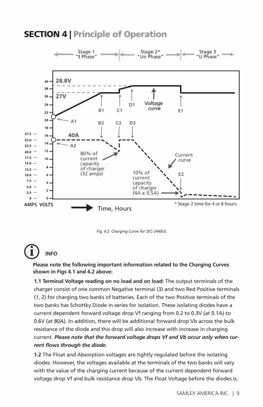
Fig. 4.2 Charging Curve for SEC-2440UL
i
INFO
Please note the following important information related to the Charging Curves shown in Figs 4.1 and 4.2 above:
1.1 Terminal Voltage reading on no load and on load: The output terminals of the
chargerconsistofonecommonNegativeterminal(3)andtwoRedPositiveterminals
(1,2)forchargingtwobanksofbatteries.EachofthetwoPositiveterminalsofthe
twobankshasSchottkyDiodeinseriesforisolation.Theseisolatingdiodeshavea
currentdependentforwardvoltagedropVfrangingfrom0.2to0.3V(at0.1A)to
0.6V(at80A).Inaddition,therewillbeadditionalforwarddropVbacrossthebulk
resistance of the diode and this drop will also increase with increase in charging
current. Please note that the forward voltage drops Vf and Vb occur only when cur-
rent flows through the diode.
1.2TheFloatandAbsorptionvoltagesaretightlyregulatedbeforetheisolating
diodes.However,thevoltagesavailableattheterminalsofthetwobankswillvary
withthevalueofthechargingcurrentbecauseofthecurrentdependentforward
voltagedropVfandbulkresistancedropVb.TheFloatVoltagebeforethediodesis,
10 | SAMLEX AMERICA INC.
SECTION 4 | Principle of Operation
therefore,set0.2to0.3Vhighertocompensatefortheforwarddropsduringfloat
conditionwhenthechargingcurrentwouldhavedroppedtolessthan1A.Hence,
theoutputvoltageattheterminalsofthetwobanksatnoload(nothingconnected
totheterminalsofthebanks)willread0.2to0.3Vhigherbecausethereisnofor-
wardvoltagedropasthereisnocurrentflowthroughthediodes.Thevoltagesare
specifiedwithrespecttocharging/loadcurrentasfollows:
AbsorptionStage(“UO”Phase)of14.4/14VforSEC-1280UL At8A+/-0.5A
AbsorptionStage(“UO”Phase)of28.8/28VforSEC-2440UL At4A+/-0.5A
FloatStage(“U”Phase)of13.5VforSEC-1280UL At0.1A
FloatStage(“U”Phase)of13.5VforSEC-2440UL At0.1A
1.3 Pleasealsonotethattheoutputvoltageatthetwobanksmaydifferbetween
0.2to0.6Vdependinguponthedifferentvaluesofthechargingcurrentbeingdeliv-
eredthrougheachasaresultofdifferentvaluesofvoltagedropsVfandVb.
2.1 Standard Temperature Conditions:Thechargingvoltagesshownpertaintobat-
teryelectrolytetemperatureof77°F(25°C)
3.1 Charger / Battery Voltage / Current Values:Whenthebatteryisconnectedto
thechargerandthechargerisinONcondition,thevoltageatthecommoncharger
/batteryterminalswillbetheactualbatteryterminalvoltagecorrespondingtoits
stateofchargeONLYwhenthechargerisin“currentlimitcondition”andissup-
plying80AforSEC-1280ULand40AforSEC-2440UL.WhenthechargerisNOTin
“currentlimit”conditionandissupplying<80AforSEC-1280ULor<40Afor
SEC-2440A,itsterminalvoltagewillbenearlyregulatedandwillbenearlyequalto
thesetBulk/FloatVoltageof13.5VforSEC-1280UL(27VforSEC-2440UL)ornearly
equaltotheAbsorptionVoltageof14.4/14VforSEC-1280UL(28.8V/28VforSEC-
2440UL).Undertheseconditions,thebatteryterminalvoltagewillalsobeat13.5
(27V)or14.4/14V(28.8V/28V)although the actual intrinsic terminal voltage of the
battery corresponding to its State of Charge at that point of time will be lower.
3.2 Thevoltagecurveshowsthevoltageatthechargeroutputterminals,whichwill
bethesameasthevoltageatthebatteryterminals(assumingthatthereisnovolt-
agedropalongthewiresconnectingthechargertothebatteries)
3.3.TheCurrentCurveshowsthecurrentbeingdrawnbythebattery

10 | SAMLEX AMERICA INC. SAMLEX AMERICA INC. | 11
SECTION 4 | Principle of Operation
STAGE 1- BULK CHARGE STAGE (“I” PHASE) InthisstageSEC-1280ULoutputsvoltageof13.5VDCandSEC-2440Aoutputs27V. ThefollowingexplanationisforSEC-1280UL.ExplanationforSEC-2440ULwillbe samebutthevoltagevalueswillbe2timesandcurrentvalueswillbehalfascomparedto SEC-1280UL.
NOTE: For explanation purpose, it is assumed that the battery is deeply discharged to around 10.5 / 21V when charging is initiated.
Whenthechargerisswitchedon,thebatterywilltrytodrawverylargecurrent=(13.5V-10.5V)÷Internalresistance(0.02Ω)=150Awhichwillbemuchhigherthanthecurrentlimitvalueof80A.Thechargerwillentercurrentlimitcondition(pointA2),itsinternalvoltagewilltrytodropbutwillbeclampedtotheterminalvoltageofthebatteryi.e.10.5V(pointA1).Thebatterystartschargingatconstantcurrentof80A(Sec-tionA2-B2)anditsintrinsicvoltagestartsrisingalmostlinearly(SectionA1-B1).Whenitsintrinsicvoltageapproaches13.5V,thecurrentdrawnbythebatterywillreduceto<80A.Atthispoint(B2),thechargerwillexitcurrentlimitandwilloutputaconstantvoltageof13.5V(pointB1).Asthebatterychargesfurtherunderconstantvoltageof13.5V(SectionB1–C1),itsintrinsicvoltagerisesfurtheranditscurrentstartstotaperdown(SectionB2–C2).Thecurrenttapersdownbecausetheintrinsicbatteryvoltageisrisingandthedifferentialvoltagebetween13.5Vofthechargerandintrinsicvoltageofthebatteryisreducingthereby,lessercurrentisdrivenintothebattery.Taperingchargeisprovidedatthistransitiontoreducesurfacechargeeffecttoensurethatthechargeslowlydiffusestotheinternalthicknessoftheplatesandpreventsovercharging.Whenthechargingcurrenttapersdownto80%oftheratedcapacityofthecharger(64AforSEC-1280ULand32AforSEC-2440UL)atpoint“B2”,thechargertransitionstothenextStage2-AbsorptionBoostStage(“UO”Phase)
Charging Characteristics During This Stage Are As Follows:
• Batteryvoltagerisesslowlyandalmostlinearly(itwillstartrisingsharplyat thebeginningofthenextAbsorptionStage2).
• TheentirechargingcurrentisusedtoconvertLeadSulfatetoSpongeLeadat theNegativeplatesandtoLeadDioxideatthePositiveplates.
• Thereisnogassingandthechargingefficiencyishigh-around91%.
• Therestoredcapacityinthisstageisinverselyproportionaltothechargingrate(duetoPeukertEffect).Thismeansthatasthechargingrateisincreased,thecapacityrestoredreduces.Thisstagerestores60%ofcapacityatchargingrate ofC/5,70%to75%capacityatchargingrateofC/10and85%to90%of capacityatchargingrateofC/20
• RedLEDmarked“IPhase”willbelitontheoptionalRemoteControl Model900-RC
12 | SAMLEX AMERICA INC.
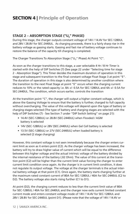
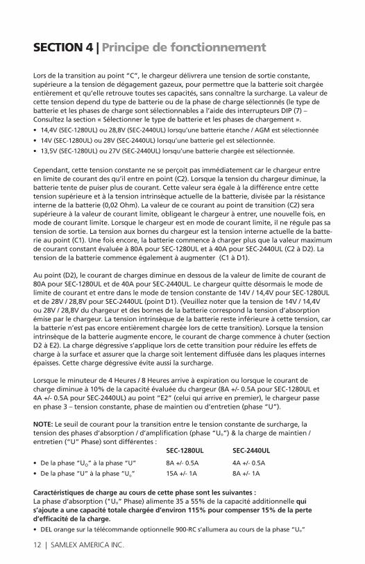
STAGE 2 – ABSORPTION STAGE (“U0” PHASE)Duringthisstage,thechargeroutputsconstantvoltageof14V/14.4VforSEC-1280ULand28V/28.8VforSEC-2440UL.Aschargingproceeds,thereisafairlysharpriseinthebatteryvoltageasgassingstarts.Gassingandfastriseofbatteryvoltagecontinuestorestore the balance of the capacity till charging is completed.
TheChargerTransitionsToAbsorptionStage(“UO”Phase)AtPoint“C”. Assoonasthechargertransitionstothisstage,auserselectable4Hr/8HrTimerisstartedwiththehelpofDIPSwitches(7)(Seepage22under“Selectingtimeforstage2-AbsorptionStage”).ThisTimerdecidesthemaximumdurationofoperationinthisstageandsubsequenttransitiontothefinalconstantvoltageFloatStage3atpoint“E”.The duration of operation in this stage is also determined by another condition where thetransitiontothenextFloatStageatpoint“E”occurswhenthechargingcurrentreducesto10%ortheratedcapacityi.e.8A+/-0.5AforSEC-1280ULand4A+/-0.5AforSEC-2440UL.Thecondition,whichoccursearlier,controlsthetransition
Atthetransitionpoint“C”,thechargerwilloutputahigherconstantvoltage,whichisabovetheGassingVoltagetoensurethatthebatteryisfurther,chargedtofullcapacitywithoutovercharging.Thevalueofthisvoltagewilldependuponthetypeofbatteryorchargingstagesselected(ThetypeofbatteryandchargingstagesareselectedwiththehelpofDIPSwitches(7)-SeeSection7under“DIPSwitchSetting”onpage21):
• 14.4V(SEC-1280UL)or28.8V(SEC-2440UL)whenFlooded/AGM battery is selected
• 14V(SEC-1280UL)or28V(SEC-2440UL)whenGelCellbatteryisselected
• 13.5V(SEC-1280UL)or27V(SEC-2440UL)whenloadedbatteryis selected(2stagecharging)
However,thisconstantvoltageisnotseenimmediatelybecausethechargerenterscur-rentlimitassoonasitenterspoint(C2).Asthechargervoltagehasbeenincreased,thebatterywilltrytodrawhighervalueofcurrentwhichwillbeequaltothedifferencebetweenthishighervoltageandtheactualintrinsicvoltageofthebatterydividedbytheinternalresistanceofthebattery(.02Ohm).Thevalueofthiscurrentatthetransi-tionpoint(C2)willbehigherthanthecurrentlimitvalueforcingthechargertoentercurrentlimitconditiononceagain.Asthechargerisincurrentlimitcondition,itdoesnotregulateitsoutputvoltage.Thevoltageatthechargerterminalsistheactualinter-nalbatteryvoltageatthatpoint(C1).Onceagain,thebatterystartschargingfurtheratthemaximumratedconstantcurrentof80AforSEC-1280UL/40AforSEC-2440UL(C2toD2).Thebatteryvoltagealsostartsrisingfurther(C1toD1).
Atpoint(D2),thechargingcurrentreducestolessthanthecurrentlimitvalueof80AforSEC-1280UL/40AforSEC-2440ULandthechargernowexitscurrentlimitedconstantcurrentmodeandentersconstantvoltagemodeof14V/14.4VforSEC-1280ULand 28V/28.8VforSEC-2440UL(pointD1).(Pleasenotethatthevoltageof14V/14.4Vor
SECTION 4 | Principle of Operation

12 | SAMLEX AMERICA INC. SAMLEX AMERICA INC. | 13
SECTION 4 | Principle of Operation
28V/28.8VatboththechargerandbatteryterminalsistheconstantAbsorptionVolt-agebeingputoutbythecharger.Theintrinsicvoltageofthebatteryisstilllowerthanthisvoltageasthebatteryisstillnotfullychargedatthistransition).Astheintrinsicvoltageofthebatteryrisesfurther,thechargingcurrentstartstaperingdown(sectionD2toE2).Taperingchargeisprovidedatthistransitiontoreducesurfacechargeeffecttoensurethatthechargeslowlydiffusestotheinternalthicknessoftheplatesandpreventsovercharging.
Whenthe4Hr/8HrTimerrunsoutorwhenthechargingcurrenttapersdownto10%oftheratedcapacityofthecharger(8A+/-0.5AforSEC-1280ULand4A+/-0.5AforSEC-2440UL)atpoint“E2”(whicheverisearlier),thechargertransitionstothenextStage3-ConstantVoltage,FloatorMaintenanceChargeStage(“U”Phase)
NOTE: Thethresholdofcurrentforchange-overbetweentheConstantOverchargeVolt-age,TimedVoltageAbsorption/BoostStage(“U0”Phase)&theFloat/MaintenanceChargeMode(“U”Phase)aredifferentasfollows:
SEC-1280UL SEC-2440UL From“Uo”Phaseto“U”Phase 8A+/-0.5A 4A+/-0.5A From“U”Phaseto“Uo”Phase 15A+/-1A 8A+/-1A
Charging Characteristics During This Stage Are As Follows:
• TheAbsorptionStage(“UO”Phase)feedsadditional35%to55%ofthecapacitythataddsuptoatotalchargedcapacityofaround115%totakecareofaround15%lossof charging efficiency.
• OrangeLEDmarked“UO”PhaseontheoptionalRemoteControl900-RCwillbelit
STAGE 3 - CONSTANT VOLTAGE, FLOAT OR MAINTENANCE CHARGE STAGE (U PHASE) Duringthismode,thechargeroutputsaconstantvoltage"U"=13.5V(SEC-1280UL)or27V(SEC-2440UL).Thishelpsinmaintainingfullcapacityofthebatteryandalsopro-videsreplacementchargetoovercomeselfdischargeofthebattery.Thebattery canremainconnectedinthisstageindefinitelywithouttheriskofdischarging.
Charging characteristics during this stage are as follows: GreenLEDmarkedFloatStage(“U”Phase)ontheoptionalRemoteControl 900-RCwillbelit.

14 | SAMLEX AMERICA INC.
SECTION 4 | Principle of Operation
! CAUTION!
3stagechargingisrecommendedforchargingstand-alone,unloadedbatteries(thereisnoloadconnectedtothebatterywhenitisbeingcharged).Ifaloadisalsoconnectedsimultaneously,apartofthecharger’soutputcurrentwillbedivertedtothisload.Thus,thechargermayremainlockedinStage2ifthecurrentdrawnbytheloadismorethanthepresetvalueofthresholdcurrentdeterminingchangeoverfromStage2toStage3.Thiswillleadtoover-charg-ing and loss of electrolyte.
Forchargingabatterywhenaloadisalsoconnectedsimultaneously,Stage2voltageshouldbesameasStage3.Select“LoadedBattery”withthehelpofDIPSwitchesmarked“Mode”(7)-SeeSection7under“DIPSwitchSetting”onpage 21.
SECTION 5 | Protections
The charger has the following protections:
SHORT CIRCUIT SHUT DOWN Incaseofashortcircuitontheoutputside,theoutputofthechargerwillbeshutdown.AnothersymptomofshortcircuitshutdownisthatthefanwillbeONtilltheunitisresetorswitchedOFF.OntheoptionalRemoteControl900-RC,GreenLEDmarked"Power"andRedLED"IPhase"willbelit.ThechargerwillbelatchedinthisshutdownconditionandwillNOTrecoverautomaticallyevenaftertheshortcircuitconditionisremoved.Toreset,theACinputpowerON/OFFswitchatthebackoftheunithastobeswitchedOFFandONagain.
OVER LOAD CURRENT LIMITING Thecurrentdrawnbytheloadisautomaticallylimitedtoamaximumof80Afor SEC-1280UL(40A+/-1Ain“HalfPowerMode”)and40AforSEC-2440UL(20A+/-1Awhenin“HalfPowerMode”).Iftheloadtriestodrawahighercurrentthantheselim-its,theoutputvoltageoftheunitwillstarttodrop.Theunitwillautomaticallyrecoverwhentheoverloadconditionisremoved.
REVERSE BATTERY CONNECTION – DC SIDE FUSES WILL BLOW TheoutputisinternallyfusedontheDCside-3x30AfusesforSEC-1280ULand3x15AfusesforSEC-2440UL.Incase,thepolarityofthebatteryconnectionisreversed,thefuse(s)willblow.AnothersymptomofblownfuseonDCsideisthatthefanwillbeONtilltheunitisswitchedOFF.OntheoptionalRemoteControl900-RC,GreenLEDmarked"Power"andRedLEDmarked"IPhase"willbelit.

14 | SAMLEX AMERICA INC. SAMLEX AMERICA INC. | 15
SECTION 5 | Protections
COOLINGThechargeriscooledbyconvectionandinaddition,hasafanforforcedair-cooling.The operation of the fan is controlled by the current supplied by the charger and will be switchedONandOFFautomaticallyasfollows:
SEC-1280UL SEC-2440UL
SwitchONcurrent 15A+/-1A 8A+/-1A
Switch OFF current 8A+/-0.5A 4A+/-0.5A
NOTE:Oncethefanswitchesonatthespecifiedcurrentthreshold,itwillswitchoffatalowerthreshold.Forexample,thefaninSEC-1280ULswitchesONat15AbutswitchesOFFat8A.ThisistopreventthefanfromoscillatingbetweenONandOFFconditionsduetominorfluctuationsinloadcurrent
OVER TEMPERATURE SHUTDOWN
! CAUTION!
Keepthechargerinawellventilated,coolandopenarea.DONOTBLOCKTHEVENTHOLESonthesidesorthedischargeopeningsofthecoolingfan.Keepatleast 6” clearance on all sides
In case the fan fails or if the cooling is not adequate due to higher ambient tempera-ture,inadequateaircirculationorblockageofairventilationopenings,thetemperatureinsidetheunitwillrise.Atemperaturesensorismountedoninthewindingsofthepowertransformer.At105°C+/-5°Cthethermalsensorwillactivateandshutdowntheoutputvoltageofthecharger.ThefanwillbeON.OntheoptionalRemoteControl 900-RC,GreenLEDmarked"Power"andRedLEDmarked"IPhase"willbelit.The chargerwillbelatchedinthisshutdownconditionandwillNOTresetautomaticallyevenaftertheunithascooleddown.Toreset,theACinputpowerON/OFFswitchatthebackoftheunithastobeswitchedOFFandONagain.
PROTECTION AGAINST TRANSIENTS / SURGES IN THE AC INPUT Inanumberoflocations,theAClineinputisnotcleanandmaycontainhighvolt-agetransients/surges.Topreventdamagetotheinternalcomponentsagainsttheseunwantedhighvoltages,thechargerusesaMOV(MetalOxideVaristor)forprotection.Ifsurge/transientvoltagehigherthanapproximately170VACin120VMode/340VACin230VACModeappearintheACinput,theMOVwillconductandwillblowtheACside fuse.

16 | SAMLEX AMERICA INC.
SECTION 6 | Installation
INSTALLATION DIMENSIONSInstallationdimensionsaregivenbelow.DimensionsaresameforSEC-1280ULandSEC-2440UL.
SEC-1280-2440UL Top View Dimensions
2
244
381
350
5
75
2
75
200
244
97
9

16 | SAMLEX AMERICA INC. SAMLEX AMERICA INC. | 17
SECTION 6 | Installation
LOCATION, MOUNTING AND SAFETY Thechargerisrequiredtobeinstalledinasafe,wellventilatedanddrylocation.Pleaseseethedetailsgivenunder“ImportantSafetyPrecautions”.Thechargercanbemountedhorizontallyorvertically.Whenmountingverticallyonawallorabulkhead,pleaseensurethattheaxisofthefanrotorishorizontali.e.thefanexhaustopeningshouldfaceleftorrightbutNOTfaceupordown.
WARNING!
MountingtheunitverticallyonaverticalsurfacewiththefanopeningfacingupordownisNOTallowedforsafety.Thisistopreventfallingofobjectsintothe unit through the fan grille when the fan opening faces up. If fan opening facesdown,hotdamagedcomponentsmayfallout.
OUTPUT CONNECTORS Connectorswithtubular,screwdowntypeofterminalsareusedforoutputconnection.Thediameterofthetubularholeoftheconnectoris8mm(0.31inches).Twopositiveoutputconnectors(1,2)areprovidedforconnectingtothePositiveterminalsofthe2banksofbatteries.Onecommonconnector(3)isprovidedfortheNegativeconnection.ThesetscrewsizeisM8.
TERMINAL LUGS FOR CONNECTION TO THE CHARGER Forfirmconnectionwhenusingstrandedwire,crimp/solder“pin”styleterminallugsonthechargerendoftheDCwiresusedforconnectingtothebattery/otherDCloads.3piecesof“pin”styleterminallugshavebeenprovidedasfollows:
• ForSEC-1280UL WillaccommodateuptoAWG#2wire/35mm2 wire
• ForSEC-2440UL WillaccommodateuptoAWG#4wire/25mm2 wire
WIRES Toavoidpolarityerrorsandpossibledamage,neverusewiresofonlyonecolor.UseRedinsulatedwire(s)forPositiveconnection(s)andBlackforNegativeconnection(s).RecommendedDCwiresizesaregivenbelow(Basedonavoltagedropof2%).ThelengthinfeetisthelengthofthepairofthepositiveandnegativeDCwiresfromthechargertothebattery/otherDCloads.
Distance From Battery SEC-1280UL SEC-2440UL
Up to 6 ft. AWG#2 AWG#8
6 to 10 ft AWG#1/0 AWG#6
10 to 20 ft. AWG#3/0 AWG#4
TERMINATION OF WIRE ENDSForfirmconnectionwhenusingstrandedwire,wireendsfortheconnectiontothe chargershouldbeterminatedwithpintypesoflugsthathavebeenprovided.
18 | SAMLEX AMERICA INC.
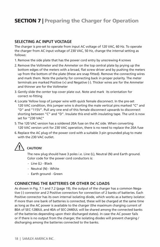
SELECTING AC INPUT VOLTAGEThechargerispre-settooperatefrominputACvoltageof120VAC,60Hz.TooperatethechargerfromACinputvoltageof230VAC,50Hz,changetheinternalsettingasfollows:
1.Removethesideplatethathasthepowercordentrybyunscrewing4screws
2.RemovetheVoltmeterandtheAmmeteronthetopcentralplatebypryingupthebottomedgesofthemeterswithabroad,flatscrewdriverandbypushingthemetersupfromthebottomoftheplate(thesearesnapfitted).Removetheconnectingwiresandmarkthem.Notethepolarityforconnectingbackinproperpolarity.ThemeterterminalsaremarkedPositive(+)andNegative(-).ThickerwiresarefortheAmmeterandthinnerarefortheVoltmeter
3.Gentlyslidethecentertopcoverplateout.Noteandmarkitsorientationfor correct re-fitting
4.LocateYellowloopofjumperwirewithquickfemaledisconnect.Inthepre-set 120VACcondition,thisjumperwireisshortingthemaleverticalpinsmarked“C”and“D”and“115V”.Pullanyoneendofthisfemaledisconnectupwardstodisconnectshortingbetween“C”and“D”.Insulatethisendwithinsulatingtape.Theunitisnowsetfor“230VAC”
5.The120VACversionhasasoldered20AfuseontheACside.Whenconverting 120VACversionunitfor230VACoperation,thereisnoneedtoreplacethe20Afuse
6.ReplacetheACplugofthepowercordwithasuitable3pingroundedplugtomatewiththe230VACoutlet.
! CAUTION!
Thenewplugshouldhave3polesi.e.Line(L),Neutral(N)andEarthground.Color code for the power cord conductors is:
- Line(L)-Black
- Neutral(N)-White
- Earthground-Green
CONNECTING THE BATTERIES OR OTHER DC LOADS AsshowninFig.7.1and7.2(page19),theoutputofthechargerhasacommonNega-tive(-)connectorand2Positiveconnectorsforconnectionof2banksofbatteries.EachPositiveconnectorhasitsowninternalisolatingdiode,whichworksasabatteryisolator.Ifmorethanonebankofbatteriesisconnected,thesewillbechargedatthesametimeaslongastheACpowerisavailabletothecharger(themaximumchargingcurrentof80AofSEC-1280ULand40AofSEC-2440ULwillbesharedamongtheconnectedbanksofthebatteriesdependingupontheirdischargedstates).IncasetheACpowerfailsorifthereisnooutputfromthecharger,theisolatingdiodeswillpreventcharging/dischargingamongthebatteriesconnectedtothebanks.
SECTION 7 | Preparing the Charger for Operation

18 | SAMLEX AMERICA INC. SAMLEX AMERICA INC. | 19
SECTION 7 | Preparing the Charger for Operation
StarterBattery
Auxilary /HouseBattery
Battery 4 Battery 3 Battery 2 Battery 1
Negative Wire “B”
Positive Wire “A”
Fig 7.1 Connecting 2 separate battery systems to 2 separate banks
Fig. 7.2 Connecting bank of paralleled batteries to single bank
20 | SAMLEX AMERICA INC.
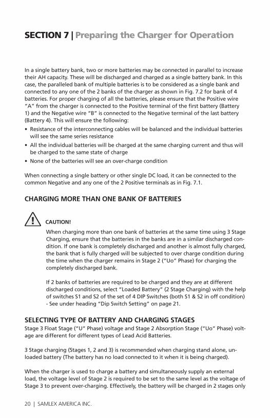
Inasinglebatterybank,twoormorebatteriesmaybeconnectedinparalleltoincreasetheirAHcapacity.Thesewillbedischargedandchargedasasinglebatterybank.Inthiscase,theparalleledbankofmultiplebatteriesistobeconsideredasasinglebankandconnectedtoanyoneofthe2banksofthechargerasshowninFig.7.2forbankof4batteries.Forproperchargingofallthebatteries,pleaseensurethatthePositivewire“A”fromthechargerisconnectedtothePositiveterminalofthefirstbattery(Battery1)andtheNegativewire“B”isconnectedtotheNegativeterminalofthelastbattery(Battery4).Thiswillensurethefollowing:
• Resistanceoftheinterconnectingcableswillbebalancedandtheindividualbatterieswill see the same series resistance
• Alltheindividualbatterieswillbechargedatthesamechargingcurrentandthuswillbe charged to the same state of charge
• Noneofthebatterieswillseeanover-chargecondition
WhenconnectingasinglebatteryorothersingleDCload,itcanbeconnectedtothecommonNegativeandanyoneofthe2PositiveterminalsasinFig.7.1.
CHARGING MORE THAN ONE BANK OF BATTERIES
! CAUTION!
Whenchargingmorethanonebankofbatteriesatthesametimeusing3StageCharging,ensurethatthebatteriesinthebanksareinasimilardischargedcon-dition.Ifonebankiscompletelydischargedandanotherisalmostfullycharged,thebankthatisfullychargedwillbesubjectedtooverchargeconditionduringthetimewhenthechargerremainsinStage2(“Uo”Phase)forchargingthecompletelydischargedbank.
If2banksofbatteriesarerequiredtobechargedandtheyareatdifferentdischargedconditions,select“LoadedBattery”(2StageCharging)withthehelpofswitchesS1andS2ofthesetof4DIPSwitches(bothS1&S2inoffcondition)-Seeunderheading“DipSwitchSetting”onpage21.
SELECTING TYPE OF BATTERY AND CHARGING STAGES Stage3FloatStage(“U”Phase)voltageandStage2AbsorptionStage(“Uo”Phase)volt-agearedifferentfordifferenttypesofLeadAcidBatteries. 3Stagecharging(Stages1,2and3)isrecommendedwhenchargingstandalone,un-loadedbattery(Thebatteryhasnoloadconnectedtoitwhenitisbeingcharged).
Whenthechargerisusedtochargeabatteryandsimultaneouslysupplyanexternalload,thevoltagelevelofStage2isrequiredtobesettothesamelevelasthevoltageofStage3topreventover-charging.Effectively,thebatterywillbechargedin2stagesonly
SECTION 7 | Preparing the Charger for Operation
20 | SAMLEX AMERICA INC. SAMLEX AMERICA INC. | 21
SECTION 7 | Preparing the Charger for Operation
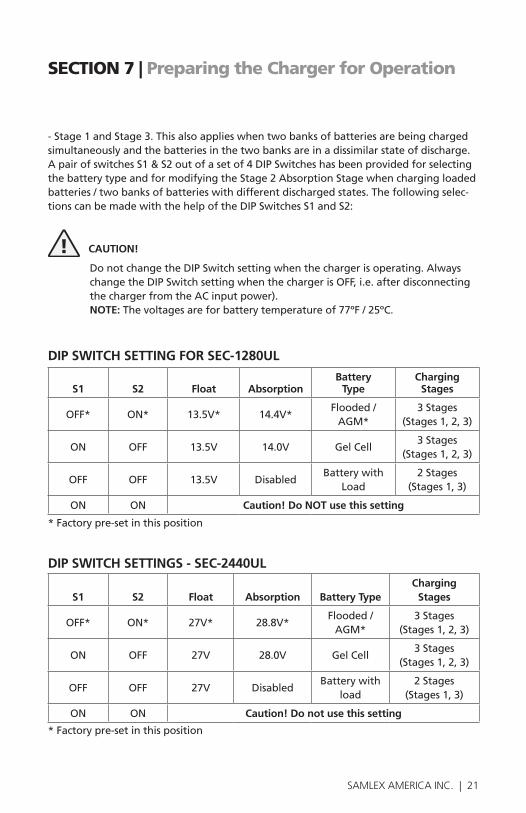
-Stage1andStage3.Thisalsoapplieswhentwobanksofbatteriesarebeingchargedsimultaneouslyandthebatteriesinthetwobanksareinadissimilarstateofdischarge.ApairofswitchesS1&S2outofasetof4DIPSwitcheshasbeenprovidedforselectingthebatterytypeandformodifyingtheStage2AbsorptionStagewhenchargingloadedbatteries/twobanksofbatterieswithdifferentdischargedstates.Thefollowingselec-tions can be made with the help of the DIP Switches S1 and S2:
! CAUTION!
DonotchangetheDIPSwitchsettingwhenthechargerisoperating.AlwayschangetheDIPSwitchsettingwhenthechargerisOFF,i.e.afterdisconnectingthechargerfromtheACinputpower).NOTE:Thevoltagesareforbatterytemperatureof77ºF/25ºC.
DIP SWITCH SETTING FOR SEC-1280UL
S1 S2 Float AbsorptionBattery
TypeCharging
Stages
OFF* ON* 13.5V* 14.4V*Flooded/AGM*
3Stages(Stages1,2,3)
ON OFF 13.5V 14.0V GelCell3Stages
(Stages1,2,3)
OFF OFF 13.5V DisabledBattery with
Load2 Stages
(Stages1,3)
ON ON Caution! Do NOT use this setting
* Factory pre-set in this position
DIP SWITCH SETTINGS - SEC-2440UL
S1 S2 Float Absorption Battery TypeCharging
Stages
OFF* ON* 27V* 28.8V*Flooded/ AGM*
3Stages (Stages1,2,3)
ON OFF 27V 28.0V GelCell3Stages
(Stages1,2,3)
OFF OFF 27V DisabledBattery with
load2 Stages
(Stages1,3)
ON ON Caution! Do not use this setting
* Factory pre-set in this position

22 | SAMLEX AMERICA INC.
! CAUTION! PLEASE ENSURE THAT POSITION S1- ON AND S2 - ON IS NEVER SELECTED
SELECTING THE TIME FOR STAGE 2 - ABSORPTION STAGE (“U0” Phase)Stage2-AbsorptionStage(“Uo”Phase)iscontrolledbyaninternaltimercircuit.Timeof4hoursor8hourscanbeselectedwiththehelpofapairofswitchesS3&S4ofthesetof4DIPSwitches(5).Checkwiththebatterymanufacturerfortheoptimumsetting.Thepresetvalueis4Hrs.Selectthetimesasfollows:
Time DIP Switch S3 DIP Switch S4 Type of Battery
4 hours* OFF* ON* Flooded/WetCell
8 hours ON OFF GelCell&AGM
Disable OFF OFF -
* Factory preset in this position
! CAUTION!PLEASE ENSURE THAT POSITION S3- ON AND S4 - ON IS NEVER SELECTED
REDUCTION OF MAXIMUM CHARGING CAPACITY TO HALF FOR SAFE CHARGING OF LOWER CAPACITY BATTERIES - HALF POWER MODEBatteriesshouldnotbechargedatveryhighcurrentstoensurelonglife.Unlessap-provedbythemanufacturer,themaximumchargingcurrentshouldbelimitedtoapproximatelyC/10(whereCistheAhcapacityofthebatteryat20HourRate).Thus,attheratedcurrentcapacities(80AforSEC-1280ULand40AforSEC-2440UL),theAhcapacity of the battery that should be charged with the charger will be:
• 80Ax10=800AhforSEC-1280UL
• 40Ax10=400AhforSEC-2440UL
IfbatterywithlowerAhcapacityischargedatthefullchargingrate,thebatterylifeislikelytobereduced.
Aprovisionhasbeenmadetoreducethemaximumchargingcurrenttoapproximatelyhalf:40A+/-1AforSEC-1280UL&20A+/-1AforSEC-2440UL.Thismodeistermedas“HalfPowerMode”.Thismodecanbeselectedbypressingpushswitchmarked“HalfPowerMode”(8).Whenselected,aGreenLEDmarked“HalfOn”(5)willbelighted.When“HalfPowerMode”isselected,batterieswiththefollowinglowercapacitiescanbesafelychargedatC/10chargingrate:
• SEC-1280UL-400Ah
• SEC-2440UL-200Ah
SECTION 7 | Preparing the Charger for Operation

22 | SAMLEX AMERICA INC. SAMLEX AMERICA INC. | 23
SECTION 7 | Preparing the Charger for Operation
TEMPERATURE COMPENSATION Thecellvoltagesofabatterydependuponthetemperatureofthecellsinsidethebat-tery.ThecellshaveaNegativeTemperatureCoefficient-theirvoltagelevelsincreaseatlowertemperatureanddecreaseathighertemperature.TheNegativeTemperatureCoefficientis-2.5mV/ºF/cellor-15.0mV/ºF/6cellsfora12Vbatteryor- 30.0mV/ºF/12cellsfora24Vbattery.
Thebatteryandbatterychargervoltagesarenormallyspecifiedatatemperatureof 77ºF(25ºC).Thus,ifthebatterytemperatureisconsiderablylowerthanorhigherthan77ºF,itwillbeunder-chargedorover-chargedunlessthebatterychargerhastempera-ture compensation.
TEMPERATURE SENSOR PROBE TF-500 Thischargerhasaprovisionfortemperaturecompensation.Atemperaturesensorunit-ModelNo.TF-500(Fig.7.3)isprovidedforthispurpose.
Fig. 7.3. Temperature Sensor Model No. TF-500
! CAUTION!
This temperature sensor is matched and calibrated for each battery charger and should not be interchanged with the sensor from another battery charger.
Thetemperaturesensorcomeswith5Metercable.Ithasaplugononeend.ConnectthisplugintothejackmarkedTS(4)ontherearpanelofthecharger.Theotherendhasthetemperaturesensorelement.Mountthistemperaturesensorelementflushwiththesidesurface of the battery for proper heat transfer.
Whenthetemperaturesensorisconnected,thevoltagesduringStages2and3areautomaticallyadjustedasperthetemperatureofthebatteryandtheabovetemperaturecoefficient.
Plug TemperatureSensor Element

24 | SAMLEX AMERICA INC.
REMOTE CONTROL PANEL MODEL NO. 900-RC
Fig 7.4 Remote Control Panel Model No. 900-RC
AnoptionalwiredRemoteControlPanelModelNo.900-RC(Fig7.4above)canbeordered.Itcomeswith10metersofRJ-45,8P8CModular,Straightcable.ItispluggedintotheRemoteControlJack(6).TheRemoteControlPanelcanbeusedtoswitchON/switchOFFthechargerandalsomonitorthechargingstatusofthechargerfromaremote location. Please read the manual for the optional Remote Control Panel 900-RC for related indications.
SECTION 8 | Operation
! CAUTION!
NegativeTemperatureCoefficient(NTC)thermistorsareusedinserieswiththeACinputcircuittolimitverylargespikeofinrushcurrentdrawnbyinputsidecapacitors,whichactalmostlikeashortcircuitduringthefirsthalfcycleafterthechargerisswitchedON.WhenchargerisswitchedON,NTCisincoldstate,itsresistanceishighandhence,theinrushcur-rentspikeissuppressedtosafelevel.Itheatsupveryfastanditsresistancedropstoalmostzero.ItremainsinheatedconditionaslongasthechargerremainsswitchedON.WhenthechargerisswitchedOFF,theNTCrequiresaround2to3mintocooldownandresetitsresistancetohighcoldstatevalueforspikesuppressionthenexttimeitisneeded.Thefol-lowingprecautionsaretobetakentopreventdamagetotheNTCandtotheinputcircuit:
• DonotswitchON,switchOFFandSwitchONthechargerinquicksuccession.Afterswitch-ingOFFthecharger,waitforatleast5minutesbeforeswitchingONagaintoallowcool-ingdownoftheNTC
• Whenpoweringthechargerfromagenerator,allowthegeneratortowarmupandstabilizeinvoltagebeforeswitchingONthecharger.IfthechargerisinONconditionandthegeneratorisstarted,highvoltagetransientsproducedbythegeneratorduringstartupmaydamagetheNTC
SECTION 7 | Preparing the Charger for Operation
Remote Panel
Cable with plug

24 | SAMLEX AMERICA INC. SAMLEX AMERICA INC. | 25
SECTION 8 | Operation
SWITCHING ON / OFF ThechargerisswitchedON/OFFwiththeilluminatedACinputpowerON/OFFswitch(9)locatedontherearpaneloftheunit.TheswitchisilluminatedRedwhenswitchedON.
INDICATION OF NORMAL OPERATION AND CHARGING STATUS WhenthechargerisswitchedONwithoutanyload,thefanwillcomeonmomentarilyand switch OFF.Voltmeter(12)willindicatethevoltageattheterminalsofthecharger.Ammeter(13)willindicatethecurrentbeingdrawnfromthecharger.Whenastand-alonebatteryisbeingchargedandhaschargedfully,thecurrentwillbealmost0A.WhenthechargerisincurrentlimitconditionduringtheStage1-BulkChargeStage(“I”Phase)orStage2–AbsorptionStage(“Uo”Phase),thecurrentshownwillbefull80AforSEC-1280ULand40AforSEC-2440A. POWERING OTHER DC LOADS ThechargercanbeusedasapowersupplyorasaDCUPS(DCUninterruptiblePowerSupply.Forboththeseapplications,firstsetswitchesS1andS2ofDIPSwitchtoOFFpositiontosetthechargertoworkin2stagemode(Seeunder“DIPSwitchSetting”onpage21).
USING THE CHARGER AS A POWER SUPPLY Touseasapowersupply,firstswitchofftheDCload.ConnecttheDCloadbetweenthecommonNegativeterminalandoneofthe2Positiveterminals.Ensurethatthemaxi-mumcurrentdrawnbytheDCloadisbelowthemaximumcurrentratingofthecharger.Switch on the charger and then the DC load.
USING THE CHARGER AS A DC UPS InaDCUPS(UninterruptiblePowerSupply),thechargersimultaneouslypowerstheDCloadaswellasthebattery.AslongastheACpowertothechargerisavailableandthechargerisworkingnormally,thechargerwillsupplytheDCloadaswellascharge/floatthebattery.IncasetheACpowerfailsorifthechargerstopsworking,thebatterywillautomaticallypowertheDCload.AssoonastheACpowertothechargerisrestored,the DC load will once again be fed by the charger and at the same time the battery will be recharged.
! CAUTION!
Please ensure that the sum of the current drawn by the DC load and the currentdesiredforchargingthebatteryislessthanthemaximumcurrentcapacityofthe
charger.
TouseasaDCUPS,firstswitchOFFtheDCloadandconnectittothebattery.Nowconnectthebatterytothechargerasexplainedaboveunder.SwitchonthechargerandthenswitchontheDCload.Foroperationinthismode,setswitchesS1&S2ofDIPswitchesmarkedMode(7)toOFFfor"BatterywithLoad"application(Seeunder“DIPSwitchSetting”onpage21).
26 | SAMLEX AMERICA INC.
Thesymptomsofabnormaloperationandthepossiblecause(s)andremediesaregivenin the succeeding paragraphs.
THERE IS NO OUTPUT. THE AC POWER ON/OFF SWITCH DOES NOT ILLUMINATE WHEN SWITCHED ON. THE VOLTAGE METER DOESN’T MOVE (ON THE REMOTE PANEL, THE GREEN LED UNDER “POWER” IS OFF). •ThereisnoACinputvoltageintheoutlet:CheckthatACpowerisavailableintheACoutlet
receptacleandthatitisswitchedON.•TheACinputsidefuseisblowndueto:
- High input voltage:Checkthattheinputvoltageis120VACnominal(normalrangeis108 to132VAC).
- High voltage transients / surges in the AC input line:EnsurethattheACinputvoltageiscleananddoesnothavehighvoltagetransients/surges.Inputvoltagesurges/transients>170VACwillblowtheACsidefuse.UseasuitableAClineconditioner/surgesuppressor,ifnecessary.
- The unit has become defective:Iffuseisnotblowingduetotheabovetwocauses,theunithasbecomedefective.CallTechnicalSupportofassistance.
THERE IS NO OUTPUT VOLTAGE. THE VOLTAGE METER DOESN’T MOVE AND THE AC POWER ON/OFF SWITCH IS ILLUMINATED RED (ON THE OPTIONAL REMOTE CONTROL 900-RC, THE RED LED UNDER “I PHASE” IS LIGHTED, THE GREEN LED UNDER “POWER” IS LIGHTED). THE FAN IS ON CONTINUOUSLY.
• The DC side output fuse is blown: The DC side fuse will blow if the battery is connected in wrong polarity.EnsurethatthePositivebatterypostisconnectedtothePositiveconnectorofthecharger(eitherBank1orBank2)andtheNegativebatterypostisconnectedtotheNegativeconnector(common)ofthecharger.Replacethefusewithafuseofthespecifiedrating.
• The battery / DC load is shorted: Checkandremovetheshortcircuit.ThechargerwilllatchintheOFFconditionifitwasshutdownduetoshortcircuitandwillNOTresetautomatically.Tore-set,switchofftheACpowerinputON/OFFswitchandswitchONagain.
•Shut down due to high temperature:Checkthatthecoolingfanisworking,theairventsarenotcloggedandtheambienttemperatureisnotveryhigh.ThechargerwillbelatchedinthisshutdownconditionandwillNOTresetautomaticallyevenaftertheunithascooleddown.Toreset,theACinputpowerON/OFFswitchhastobeswitchedOFF and ON again.
•AC input has been set to 230 VAC and is being operated at 120 VAC:Checkthepositionofthein-ternaljumperforsetting120VAC/230VACoperation.For120VACoperation,thejumpershouldbeconnectedandshouldbeshortingpoints“C”and“D”onthePCB
WHEN THE CHARGER IS POWERED AND IS BEING USED AS A DC POWER SUPPLY / UPS, THE OUTPUT VOLTAGE DROPS WHEN THE DC LOAD IS SWITCHED ON OR INCREASED. The charger is being forced into current limit condition. The load is trying to draw current more thanthecurrentlimitvalueofthecharger-80AforNormaloperation&40A+/-1Afor“HalfPowerMode”forSEC-1280ULand40AforNormaloperation&20A+/-1Afor“HalfPowerMode”forSEC-2440UL(thecurrentlimitvalueisthemaximumspecifiedchargingAmps).Oncetheloadcurrentreachesthecurrentlimitvalue,thecurrentlimitcircuitisactivatedandtheoutputvoltagedrops.Someloadslikemotors,compressors,incandescentlamps,halogenlamps,heatingelements,relays,
SECTION 9 | Troubleshooting
26 | SAMLEX AMERICA INC. SAMLEX AMERICA INC. | 27
SECTION 9 | Troubleshooting
coils,capacitorsetc.drawverylargeinrush/startingcurrentswhichmayreachupto10timestheirnormaloperatingcurrents.Ensurethatthestarting/inrushcurrentorthemaximumoperatingcur-rentoftheloadislowerthanthecurrentlimitvalueofthecharger.Donotusealoadthatdrawsmorethan80A(40A+/-1Afor“HalfPowerMode”)forSEC-1280ULormorethan40A(20A+/-1Afor“HalfPowerMode”)forSEC-2440UL.Oncetheloadcurrentisreducedbelowtheabovelimitingvalues,thechargerwillrecoverautomatically.
THE BATTERY IS GETTING OVER CHARGED / OVERHEATED / LOSES WATER OR BOILS. •There is an external load connected to the battery when it is being charged:3-stagechargingis
recommendedforchargingstand-aloneorunloadedbatteries(thereisnoloadconnectedtothebatterywhenitisbeingcharged).Ifaloadisalsoconnectedsimultaneously,apartofthecharger’soutputcurrentwillbedivertedtothisload.Thus,thechargermayremainlockedinStage2ifthecurrentdrawnbytheloadismorethanthepresetvalueofthresholdcurrentdeterminingtransitionfromStage2toStage3.Thiswillleadtoovercharging,overheatingandlossofelectrolyte. Forchargingabatterywhenaloadisalsoconnectedsimultaneously,Stage2voltageshouldbethesameasStage3voltage(Stage2isdisabled).Select“LoadedBattery”withthehelpofDIPSwitchesS1andS2ofthesetof4DIPSwitches-Seeunder“DIPSwitchSetting”onpage21.
•Two banks of batteries are being charged and the batteries in the two banks are in dissimilar state of discharge:Whenchargingmorethanonebankofbatteriesatthesametimeusing3StageCharging,ensurethatthebatteriesinthebanksareinasimilardischargedcondition.Ifonebankiscompletelydischargedandanotherisalmostfullycharged,thebankthatisfullychargedwillbesubjectedtooverchargeconditionduringthetimewhenthechargerremainsinStage2forchargingthecompletelydischargedbank.
If2banksofbatteriesarerequiredtobechargedandtheyareatdifferentdischargedconditions,select“2StageCharging”withthehelpofswitchesS1andS2ofthesetof4DipSwitches(bothS1&S2inoffcondition)-Seeunder“DIPSwitchSetting”onpage21.
• Very high charging current for low Ah capacity battery: Charging rate should normally be limited toC/10unlessspecifiedotherwisebythebatterymanufacturer.Veryhighchargingratemayleadtoreductioninthecellvoltagewhengassingstartsandcanresultinhighertemperatures,lossofwater and boiling of the battery.
THE BATTERY IS TAKING EXCESSIVELY LONG TIME TO FULLY RECHARGE OR WHEN THE CHARGER IS POWERED AND IS BEING USED AS A DC POWER SUPPLY / UPS, THE OUT-PUT VOLTAGE DROPS AT LOWER DC LOAD CURRENTS. • The unit is in “Half Power Mode”:(GreenLED(8)locatedonthebottomleftcornerofthefront
paneloftheunitislighted).Whenthismodeisselected,themaximumchargingcurrentwillbeautomaticallyreducedto40A+/-1AforSEC-1280ULand20A+/-1AforSEC-2440UL.Hence,thechargingtimewillincrease.Switchoffthe“HalfPowerMode”ifthefullratedchargingcapacityisrequired.

28 | SAMLEX AMERICA INC.
BoththeACinputsideandDCoutputsidehavefuses.
TheACinputsidefuseislocatedonthePCBF1insidetheunit.Itisratedat250V,20A,TimeDelay(Size6.3mmx32mm,pig-tail).
TheDCsidefusesarelocatedinsidetheunit.Toaccessthesefuses,removethetopcover.Theseareautomotivebladefuses(forexample,“Littelfuse”TypeATO)ratedasfollows:
SEC-1280UL 3pieces,eachratedat32V,30A
SEC-2440UL 3pieces,eachratedat32V,15A
SECTION 10 | Internal Fuse Ratings
PARAMETER SEC-1280UL SEC-2440UL
NOMINALINPUTVOLTAGE Factory Preset
By changing internal jumper
120 VAC, 50 /60 Hz(108 to 132 VAC)
230 VAC, 50 / 60 Hz(207 to 253 VAC)
INPUTCURRENTAt 120 VAC inputAt 230 VAC input
15.9A8.6A
15.3A8.3A
OUTPUTVOLTAGEBulk “I Phase”
Absorption “Uo Phase”*Float “U Phase”*
13.5V +/-0.05V14V / 14.4V +/-0.05V
13.5V +/- 0.05V
27.0V +/- 0.05V28V / 28.8V +/- 0.05V
27.0V +/- 0.05V
MAXIMUMBULK CHARGINGCURRENT,I
Normal OperationHalf Power Mode
80A40A +/-1A
40A20A +/- 1A
THRESHOLDOFCURRENTFOR CHANGEOVERABSORPTIONFrom Float “U” to Absorption “Uo”From Absorption “Uo” to Float “U”
15A +/-1A8A +/-0.5A
8A +/-1A4A +/-0.5A
DURATIONOFABSORPTION/BOOSTSTAGE
4 Hrs or 8 Hrs (Switch selectable)
MAXIMUMBATTERYCAPACITY 800 Ah 400 Ah
TEMPERATURECOMPENSATION YES, with Temperature Sensor TF-500
SECTION 11 | Specifications
28 | SAMLEX AMERICA INC. SAMLEX AMERICA INC. | 29
SECTION 11 | Specifications
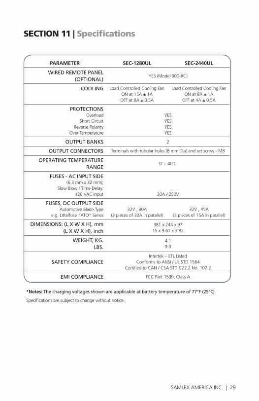
PARAMETER SEC-1280UL SEC-2440UL
WIREDREMOTEPANEL (OPTIONAL)
YES (Model 900-RC)
COOLING Load Controlled Cooling FanON at 15A ± 1AOFF at 8A ± 0.5A
Load Controlled Cooling FanON at 8A ± 1A
OFF at 4A ± 0.5A
PROTECTIONSOverload
Short CircuitReverse Polarity
Over Temperature
YESYESYESYES
OUTPUTBANKS 2
OUTPUTCONNECTORS Terminals with tubular holes (8 mm Dia) and set screw - M8
OPERATINGTEMPERATURERANGE
0˚ – 40˚C
FUSES-ACINPUTSIDE (6.3 mm x 32 mm);
Slow Blow / Time Delay:120 VAC Input 20A / 250V
FUSES,DCOUTPUTSIDEAutomotive Blade Type
e.g. Littelfuse “ATO” Series 32V , 90A
(3 pieces of 30A in parallel)32V , 45A
(3 pieces of 15A in parallel)
DIMENSIONS:(LXWXH),mm(LXWXH),inch
381 x 244 x 9715 x 9.61 x 3.82
WEIGHT,KG.LBS.
4.19.0
SAFETYCOMPLIANCEIntertek – ETL Listed
Conforms to ANSI / UL STD 1564Certified to CAN / CSA STD C22.2 No. 107.2
EMICOMPLIANCE FCC Part 15(B), Class A
*Notes:Thechargingvoltagesshownareapplicableatbatterytemperatureof77°F(25°C)
Specifications are subject to change without notice.
30 | SAMLEX AMERICA INC.
SECTION 12 | Warranty
2 YEAR LIMITED WARRANTY
SEC-1280UL/SEC-2440ULmanufacturedbySamlexAmerica,Inc.(the “Warrantor“)iswarrantedtobefreefromdefectsinworkmanshipand materialsundernormaluseandservice.Thewarrantyperiodis2yearsfor theUnitedStatesandCanada,andisineffectfromthedateofpurchase bytheuser(the“Purchaser“).
• WarrantyoutsideoftheUnitedStatesandCanadaislimitedto6months.Forawarrantyclaim,thePurchasershouldcontacttheplaceofpurchasetoobtainaReturnAuthorizationNumber.
• ThedefectivepartorunitshouldbereturnedatthePurchaser’sexpensetotheauthorizedlocation.Awrittenstatementdescribingthenatureofthedefect,thedateofpurchase,theplaceofpurchase,andthePurchas-er’sname,addressandtelephonenumbershouldalsobeincluded.
• IfupontheWarrantor’sexamination,thedefectprovestobetheresultofdefectivematerialorworkmanship,theequipmentwillberepairedorreplacedattheWarrantor’soptionwithoutcharge,andreturnedtothePurchaserattheWarrantor’sexpense.(ContiguousUSandCanadaonly)
• NorefundofthepurchasepricewillbegrantedtothePurchaser,unlesstheWarrantorisunabletoremedythedefectafterhavingareasonablenumberofopportunitiestodoso.WarrantyserviceshallbeperformedonlybytheWarrantor.AnyattempttoremedythedefectbyanyoneotherthantheWarrantorshallrenderthiswarrantyvoid.Thereshallbenowarrantyfordefectsordamagescausedbyfaultyinstallationorhook-up,abuseormisuseoftheequipmentincludingexposuretoexcessiveheat,saltorfreshwaterspray,orwaterimmersion.
• Nootherexpresswarrantyisherebygivenandtherearenowarrantieswhichextendbeyondthosedescribedherein.Thiswarrantyisexpressly inlieuofanyotherexpressedorimpliedwarranties,includinganyimpliedwarrantyofmerchantability,fitnessfortheordinarypurposesforwhichsuchgoodsareused,orfitnessforaparticularpurpose,oranyotherobli-gationsonthepartoftheWarrantororitsemployeesand representatives.
30 | SAMLEX AMERICA INC. SAMLEX AMERICA INC. | 31
SECTION 12 | Warranty
• ThereshallbenoresponsibilityorliabilitywhatsoeveronthepartoftheWarrantororitsemployeesandrepresentativesforinjurytoanypersons,ordamagetopersonorpersons,ordamagetoproperty,orlossofincomeorprofit,oranyotherconsequentialorresultingdamagewhichmaybeclaimedtohavebeenincurredthroughtheuseorsaleoftheequipment,includinganypossiblefailureofmalfunctionoftheequipment,orpartthereof.TheWarrantorassumesnoliabilityforincidentalorconsequen-tialdamagesofanykind.
Samlex America Inc. (the “Warrantor”)www.samlexamerica.com

Contact Information
Toll Free NumbersPh: 1 800 561 5885
Fax: 1 888 814 5210
Local NumbersPh: 604 525 3836
Fax: 604 525 5221
Websitewww.samlexamerica.com
USA Shipping WarehouseKent WA
Canadian Shipping WarehouseDelta BC
Email purchase orders [email protected]
11001-SEC-1280-2440UL-0616-EN

GUIDE D'UTILISATION Veuillez consulter ce manuel avant d'utiliser votre chargeur de batterie
Chargeur de batterie automatique
MODELÉS:SEC-1280ULSEC-2440UL

2 | SAMLEX AMERICA INC.
GUIDE D'UTILISATION: Chargeur de Batterie | Indice
SECTION 1: Précautions importante de sécurité ............................ 3
SECTION 2: Description et caractéristiques ................................... 5
SECTION 3: Présentation ............................................................... 6
SECTION 4: Principe de fonctionnement ...................................... 7
SECTION 5: Protections ............................................................... 13
SECTION 6: Installation ............................................................... 15
SECTION 7: Preparer Le Chargeur Pour L'Utilisation ................... 17
SECTION 8: Fonctionnement ...................................................... 23
SECTION 9: Resolution Des Problemes ........................................ 25
SECTION 10: Calibration Des Fusibles Internes ............................. 27
SECTION 11: Spécificités ................................................................ 28
SECTION 12: Guarantie ............................................................... 30
Exclusion de responsabilitéSAUF ACCORD ÉCRIT, SAMLEX AMERICA, INC. :
1. N'OFFRE AUCUNE GARANTIE QUANT À L'EXACTITUDE, L'EXHAUSTIVITÉ OU LA PERTINENCE DE TOUTE TECHNIQUE OU D'AUTRES INFORMATIONS FOURNIES DANS SES MANUELS OU D'AUTRES DOCUMENTS.
2. N'ASSUME AUCUNE RESPONSABILITÉ OU RESPONSABILITÉ POUR LES PERTES, DOMMAGES, COÛTS OU DÉPENSES, QU'IL S'AGISSE DE PARTICULIERS, DIRECTS, INDIRECTS, CONSÉCUTIFS OU ACCESSOIRES, QUI POURRAIENT DÉCOULER DE L'UTILISATION DE TELLES INFORMATIONS. L'UTILISATION DE CES RENSEIGNEMENTS SERONT ENTIÈREMENT À L'UTILISATEURS RISQUE.
Avis de droit d'auteur/Mention de réserve du droit d'auteurCopyright © 2016 par Samlex America, Inc. Tous droits réservés. L'autorisation de copier, distribuer et/ou modifier ce document est interdite sans l'autorisation expresse et écrite de Samlex America, Inc.

2 | SAMLEX AMERICA INC. SAMLEX AMERICA INC. | 3
SECTION 1 | Précautions importante de sécurité
Les symboles de sécurité suivant seront utilisés dans ce manuel pour insister sur les informa-tions liées à la sécurité lors de l’installation et de l’utilisation :
AVERTISSEMENT !
Indique une possibilité de dommages corporels chez l’utilisateur en cas de non conformité.
! ATTENTION !
Indique une possibilité de dommages de l’équipement en cas de non conformité.
i
INFO
Indique que de plus amples informations utiles sont disponibles.
Des situations dangereuses peuvent survenir si le chargeur n’est pas installe ou ne fonctionne pas correctement. Veuillez lire les instructions suivantes afin d’éviter toute blessures et dom-mages sur le chargeur.
INFORMATIONS RELATIVE A LA BATTERIE• Afinderéduirelerisqued’explosiondelabatterie,veuillezsuivrecesinstructionsetcellesindi-
quées sur la batterie.
• Nejamaisfumeretévitertouteétincelleouflammeauxenvironsdelabatterieoudumoteur.
• Chargezuniquementlesbatteriesdetypeplomb-acide(inondées/AGM/Cellulesgelées).Nepaschargerd’autrestypesdebatterietelsqueleNickelCadmium(Ni-Cd),Nickel-MetalHydride(Ni-Mh),Pilessèchesetc.D’autrestypesdebatteriespeuventexploseretprovoquerdegravesbles-sures.
• Nejamaischargerunebatteriegelée.
• Travaillerauxenvironsdebatteriesplombacideestdangereux.Lorsqu’ellesfonctionnent,lesbat-teriesgénèrentdesgazesd’hydrogèneetd’oxygèneinflammables.Prenezlesprécautionsnéces-saireslorsquevousinstallezlechargeurprèsd’unebatterieoudansuncompartimentdebatterie(Suivezlesmesuresdesécuritédonnéesparlefabricantdelabatterie).
• Nejamaispositionnerlechargeurdirectementaudessusouendessousdelabatterieencharge,desgazesetfluidesémanantdelabatteriepeuventcorroderouendommagerlechargeur.Disposezlechargeurleplusloinpossibledelabatterie,lescâblesdeCClepermettant.Nepasledisposez dans le même compartiment que celui de la batterie.
• FaitesATTENTIONpouréviterlesrisquesdechutesd’objetsmétalliquessurlabatterie.Celapour-raitprovoquerdesétincellesoucourtcircuiterlabatterieoudesélémentsélectriques,etcelapeutégalementprovoqueruneexplosion.
• Retireztoutobjetsmétalliques,telsquelesbagues,braceletsetmontreslorsquevousutilisezlesbatteries.Celles-cipeuventprovoqueruncourantdecourt-circuitsuffisammentpuisant,poursouderunebagueouautresmétauxetprovoquerainsiunevivebrulure.
• Sivousdevezenleverunebatterie,retireztoujourslabornedeterredelabatterieenpremier.Assurez-vousquetouslesaccessoiressontéteints,demanièreànepasprovoquerd’étincelles.
4 | SAMLEX AMERICA INC.
SECTION 1 | Précautions importante de sécurité
INFORMATIONS RELATIVES AU CHARGEUR • LescapacitésmaximalesAhdesbatteriesdoiventêtreslimitées,commesuit:
- SEC-1280UL: 800Ah
- SEC-2440UL: 400Ah
• Nepasfairefonctionnerlechargeurdansunendroitclosoudansunepiècemalventilée.Installez-ledansunendroitcorrectementventilé,secetfrais.
• Lechargeurnedoitpasêtreutilisédansunenvironnementhumideoumouillé.Lorsqu’ilestfixésurunbateau,assurez-vousqu’ilestàl’abridetouteséclaboussures.
• Nepasbloquerlesbouchesdeventilationoulessortiesd’aérationduventilateur.Conservezunespacelibred’aumoins15centimètrestoutautourdel’unité.
• L’installationetlebranchementdoiventêtreconformesauxCodesElectriqueslocauxetnation-aux.Ilestpréférabledefaireinstalleretdebrancherl’unitéparunélectricienprofessionnel
• Unemauvaiseinstallationsurunbateaupeutprovoquerlacorrosiondubateau.Ilestpréférablede faire installer l’unité par un électricien bateau.
• Débranchezl’alimentationélectriquedeCAduchargeuravantdebrancher/débrancherlesbat-teriesoulesautreschargesdeCC,oulorsquevoustravaillezsurlechargeur
• Débranchezl’alimentationélectriquedeCAavantdemodifierlesréglagesdesinterrupteursDIP.
• Lechâssisduchargeurestconnectéàlabrochedemiseàlaterreducordond’alimentationdelaprise.Assurez-vousqueleréceptacledelabrochedemiseàlaterredeCAalimentantlechargeur,est connecté à la terre.
• Nepasutiliserd’adaptateur.Siuntypederéceptacledemiseàlaterren’estpasdisponible,n’utilisez pas ce chargeur avant qu’une unité appropriée ne soit installée par un électricien professionnel.
• Nepasutiliserlechargeursilecordond’alimentationestendommagé.
4 | SAMLEX AMERICA INC. SAMLEX AMERICA INC. | 5
SECTION 2 | Description et Caractéristiques
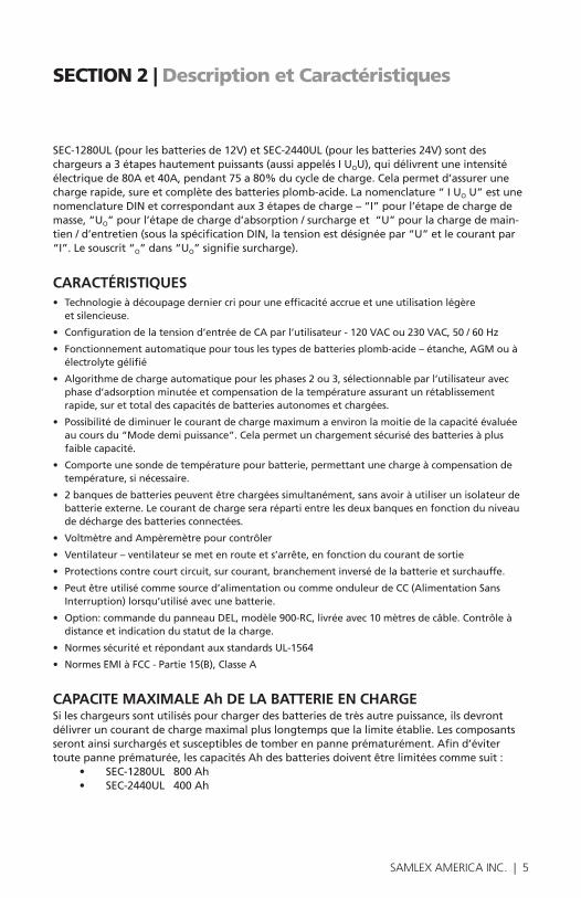
SEC-1280UL(pourlesbatteriesde12V)etSEC-2440UL(pourlesbatteries24V)sontdeschargeursa3étapeshautementpuissants(aussiappelésIUOU),quidélivrentuneintensitéélectriquede80Aet40A,pendant75a80%ducycledecharge.Celapermetd’assurerunechargerapide,sureetcomplètedesbatteriesplomb-acide.Lanomenclature“IUO U” est une nomenclatureDINetcorrespondantaux3étapesdecharge–“I”pourl’étapedechargedemasse,“UO”pourl’étapedecharged’absorption/surchargeet“U”pourlachargedemain-tien/d’entretien(souslaspécificationDIN,latensionestdésignéepar“U”etlecourantpar“I”.Lesouscrit“O”dans“UO”signifiesurcharge).
CARACTÉRISTIQUES • Technologieàdécoupagederniercripouruneefficacitéaccrueetuneutilisationlégère
et silencieuse.
• Configurationdelatensiond’entréedeCAparl’utilisateur-120VACou230VAC,50/60Hz
• Fonctionnementautomatiquepourtouslestypesdebatteriesplomb-acide–étanche,AGMouàélectrolytegélifié
• Algorithmedechargeautomatiquepourlesphases2ou3,sélectionnableparl’utilisateuravecphase d’adsorption minutée et compensation de la température assurant un rétablissement rapide,surettotaldescapacitésdebatteriesautonomesetchargées.
• Possibilitédediminuerlecourantdechargemaximumaenvironlamoitiedelacapacitéévaluéeaucoursdu“Modedemipuissance”.Celapermetunchargementsécurisédesbatteriesàplusfaible capacité.
• Comporteunesondedetempératurepourbatterie,permettantunechargeàcompensationdetempérature,sinécessaire.
• 2banquesdebatteriespeuventêtrechargéessimultanément,sansavoiràutiliserunisolateurdebatterieexterne.Lecourantdechargeserarépartientrelesdeuxbanquesenfonctionduniveaude décharge des batteries connectées.
• VoltmètreandAmpèremètrepourcontrôler
• Ventilateur–ventilateursemetenrouteets’arrête,enfonctionducourantdesortie
• Protectionscontrecourtcircuit,surcourant,branchementinversédelabatterieetsurchauffe.
• Peutêtreutilisécommesourced’alimentationoucommeonduleurdeCC(AlimentationSans Interruption)lorsqu’utiliséavecunebatterie.
• Option:commandedupanneauDEL,modèle900-RC,livréeavec10mètresdecâble.Contrôleàdistance et indication du statut de la charge.
• NormessécuritéetrépondantauxstandardsUL-1564
• NormesEMIàFCC-Partie15(B),ClasseA
CAPACITE MAXIMALE Ah DE LA BATTERIE EN CHARGE Sileschargeurssontutiliséspourchargerdesbatteriesdetrèsautrepuissance,ilsdevrontdélivreruncourantdechargemaximalpluslongtempsquelalimiteétablie.Lescomposantsserontainsisurchargésetsusceptiblesdetomberenpanneprématurément.Afind’évitertoutepanneprématurée,lescapacitésAhdesbatteriesdoiventêtrelimitéescommesuit:
• SEC-1280UL800Ah• SEC-2440UL400Ah
6 | SAMLEX AMERICA INC.
SECTION 3 | Présentation
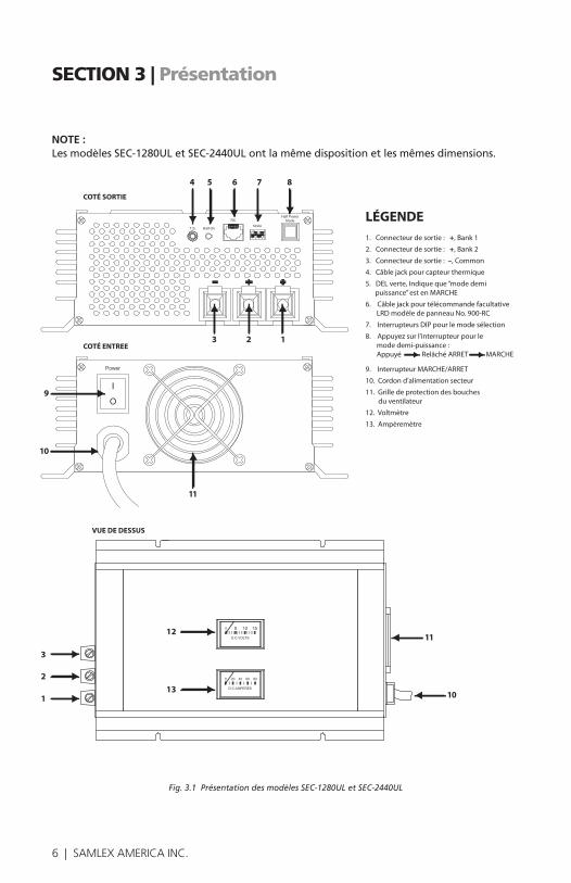
NOTE : LesmodèlesSEC-1280ULetSEC-2440ULontlamêmedispositionetlesmêmesdimensions.
Fig. 3.1 Présentation des modèles SEC-1280UL et SEC-2440UL
4 5 6 7 8
3 2 1
9
10
11
12
13
3
2
1
11
10
SEC-1280UL & SEC-2440UL
COTÉ SORTIE
COTÉ ENTREE
VUE DE DESSUS
LÉGENDE1. Connecteur de sortie : +, Bank 1
2. Connecteur de sortie : +, Bank 2
3. Connecteur de sortie : –, Common
4. Câble jack pour capteur thermique
5. DEL verte, Indique que “mode demi puissance” est en MARCHE
6. Câble jack pour télécommande facultative LRD modèle de panneau No. 900-RC
7. Interrupteurs DIP pour le mode sélection
8. Appuyez sur l’interrupteur pour le mode demi-puissance : Appuyé Relâché ARRET MARCHE
9. Interrupteur MARCHE/ARRET
10. Cordon d’alimentation secteur
11. Grille de protection des bouches du ventilateur
12. Voltmètre
13. Ampèremètre

6 | SAMLEX AMERICA INC. SAMLEX AMERICA INC. | 7
SECTION 4 | Principe de fonctionnement
i
INFORMATIONS
Pourunetotalecompréhensiondufonctionnementdeschargeursdebatterie,unecompréhension du fonctionnement des batteries plomb-acide est préférable.
Pourplusdedétailssurlafabrication,lefonctionnementetl’utilisationdesbatteries,veuillez consulter les livres blancs ou www.samlexamerica.com.
LE CHARGEUR DE BATTERIE EST UNE SOURCE D’ALIMENTATION AVEC SORTIE DC DE COURANT LIMITEE La chargeur est une source d’alimentation avec une sortie DC de courant limitée qui convertit 120/230VAC,50/60HzentensionsdeCCréguléesetlimitelecourantdesortiemaximalcomme suit :
Modèl No.Limite de courant
Tension constante lors de la charge de
masse “I”
Tension constante lors de la charge d’absorption
“U0”
Tension constante lors de la charge de maintien “U”
SEC-1280UL 80A 13,5VDC14,0VDCou 14,4VDC
13,5VDC
SEC-2440UL 40A 27VDC28,0VDCou28,8VDC
27VDC
Latensiondesortieduchargeuraucoursd’unephasedechargeestconstantejusqu’àcequela valeur limite de courant ne soit atteinte. Lorsque la batterie ou la charge de CC tente de puiserducourantsupérieuràlavaleurdelimitedecourant,lechargeurlimitelecourantala valeur de limite de courant. La tension de sortie du chargeur chute et devient inconstante. Lorsquelechargeurestconnectealabatterieestenmodelimitedecourant,latensionter-minaleduchargeurseraverrouilléealatensionterminaleintrinsèqueactuelledelabatterie(enconsidérantquelechargeursoittrèsprochedelabatterieetqu’iln’yaitpasdechutedetensionauseindescâblesconnectantlechargeurauxbatteries).
IMPEDANCE DE LA BATTERIE ET COURANT DE CHARGE L’impédanceinterned’unebatteriesaineesttrèsbasse,ellesemesureendizainesdemilliOhms(l’impédanceestplusélevéelorsquelabatterieestdéchargée,enraisondudépôtdesulfatedeplomb.L’impédancediminuelorsquelabatterieestpleinementchargée,carlesulfatedeplombestentièrementtransformeenplombetdioxydedeplomb).L’impédancemoyennepeutêtreévaluéeà20milliOhmou0,02Ohm.
Lorsquelecourantdélivreunetensioncourante(etqu’iln’estpasenlimitedecourant),lecourant de charge absorbé par la batterie peut être calculé comme suit :Courant de charge = Tension du chargeur – tension intrinsèque de la batterie ÷ résistance interne (0,02 Ohm)
8 | SAMLEX AMERICA INC.
SECTION 4 | Principe de fonctionnement
Parexemple,lorsqueSEC-1280ULestenphasedechargedemasse1,satensiondesortieestrégléea13,5VDC.Lorsqu’unebatteriecomplètementdéchargéeestchargéea10,5V,celapuiserauncouranttrèsimportant=(13,5V-10,5V)÷Resistanceinterne(0,02Ω)=150A. SEC-1280UL,limitera,cependant,soncouranta80A.
ETAPES DE CHARGELa batterie se charge en 3 phases :
• PHASE1–CHARGEDEMASSE(“I”Phase),
• PHASE2–CHARGED’ABSORPTION(Phase“U0”)et
• PHASE3-CHARGEDEFLOTTEMENT(Phase“U”)
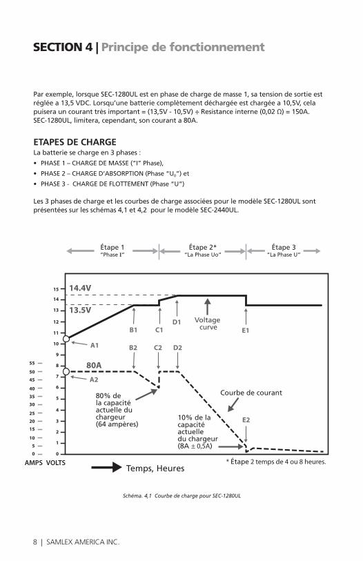
Les3phasesdechargeetlescourbesdechargeassociéespourlemodèleSEC-1280ULsontprésentéessurlesschémas4,1et4,2pourlemodèleSEC-2440UL.
Schéma. 4,1 Courbe de charge pour SEC-1280UL
Voltage curve
14.4V
13.5V
15
14
13
12
11
10
9
8
7
6
5
4
3
2
1
0
55
50
45
40
35
30
25
20
15
10
5
0
AMPS VOLTS
Fig 4.1 - SEC-1280UL Charging Curves
80A
B1 C1D1
E1
B2 C2 D2
E2
A1
A2
Étape 1“Phase I”
Étape 2*“La Phase Uo”
Étape 3“La Phase U”
* Étape 2 temps de 4 ou 8 heures.
Courbe de courant
10% de lacapacité actuelle du chargeur(8A ± 0,5A)
80% de la capacité actuelle du chargeur(64 ampères)
Temps, Heures

8 | SAMLEX AMERICA INC. SAMLEX AMERICA INC. | 9
SECTION 4 | Principe de fonctionnement
Voltage curve
28.8V
27V
30
28
26
24
22
20
18
16
14
12
10
8
6
4
2
0
27.5
25.0
22.5
20.0
17.5
15.0
12.5
10.0
7.5
5.0
2.5
0
Fig 4.2 SEC-2440UL Charging Curves
B1 C1D1
E1
B2 C2 D2
E2
40A
A1
A2
Voltage curve
AMPS VOLTS
Étape 1“Phase I”
Étape 2*“La Phase Uo”
Étape 3“La Phase U”
Courbe de courant
10% de lacapacité actuelle du chargeur(4A ± 0,5A)
80% de la capacité actuelle du chargeur(32 ampères)
* Étape 2 temps de 4 ou 8 heures.Temps, Heures
Schéma. 4,2 Courbe de charge pour SEC-2440UL
i
INFORMATIONS
Veuillez noter que les informations suivantes relatives aux courbes de charge sont présentées sur les schémas 4,1 et 4,2 ci-dessus :
1.1 Lecture de tension terminale en et hors charge : Les bornes de sortie du chargeur sont composéesd’unebornenégativecommune(3)etdedeuxbornespositivesrouges(1,2)pourchargerdeuxbanquesdebatteries.ChacunedesdeuxbornespositivesdesdeuxbanquespossèdedesdiodesSchottkyensériepourpermettrel’isolation.Cesdiodesisolantesdisposentd’uncourantquidépenddelachutedetensiondirecteVfallantde0,2à0,3V(à0,1A)jusqu’à0,6V(à80A).Deplus,ilyauraunechutedetensiondirectesupplémentaireVbàtraverslarésistance de masse de la diode et cette chute augmentera également le courant de charge. Veuillez noter que les chutes de tension directe Vf et Vb ont uniquement lieu lorsque le cou-rant circule à travers la diode. 1.2 Les tensions de maintien et d’absorption sont fermement régulées avant que les diodes nesoientisolées.Cependant,lestensionsdisponiblesauxbornesdesdeuxbanquespeuventvarieraveclavaleurducourantdecharge,enraisonducourantdépendantdelachutedetension Vf et de la chute de la résistance de masse Vb.
Latensiondemaintienavantquelesdiodesnelesoient,estparconséquent,régléeentre0,2à0,3Vsupplémentaires,afindecompenserleschutesdetensiondirecteaucoursdelaphasedemaintien,lorsquelecourantdechargeaurachutéendessousde1A.Ainsi,latensiondesortieauxbornesdesdeuxbanquesdéchargées(sansqueriennesoitbranchéauxbornesdes
10 | SAMLEX AMERICA INC.
SECTION 4 | Principe de fonctionnement
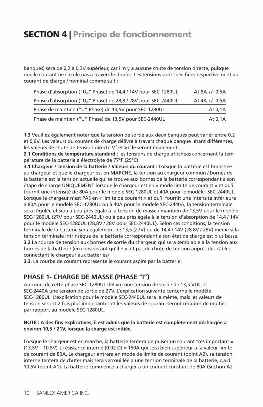
banques)serade0,2à0,3Vsupérieur,carilnyaaucunechutedetensiondirecte,puisquequelecourantnecirculepasatraverslediodes.Lestensionssontspécifiéesrespectivementaucourantdecharge/nominalcommesuit:
Phased’absorption(“UO”Phase)de14,4/14VpourSEC-1280UL At8A+/-0.5A
Phased’absorption(“UO”Phase)de28,8/28VpourSEC-2440UL At4A+/-0.5A
Phasedemaintien(“U”Phase)de13,5VpourSEC-1280UL At0,1A
Phasedemaintien(“U”Phase)de13,5VpourSEC-2440UL At0,1A
1.3 Veuillezégalementnoterquelatensiondesortieauxdeuxbanquespeutvarierentre0,2et0,6V.Lesvaleursducourantdechargedélivréàtraverschaquebanqueétantdifférentes,les valeurs de chute de tension directe Vf et Vb le seront également. 2.1 Conditions de température standard :lestensionsdechargeaffichéesconcernentlatem-pératuredelabatterieàélectrolytede77°F(25°C)3.1 Chargeur / Tension de la batterie / Valeurs du courant : Lorsque la batterie est branchée auchargeuretquelechargeurestenMARCHE,latensionauchargeurcommun/bornesdelabatterieestlatensionactuellequisetrouveauxbornesdelabatteriecorrespondantasonétapedechargeUNIQUEMENTlorsquelechargeuresten«modelimitedecourant»etqu’ilfournituneintensitéde80ApourlemodèleSEC-1280ULet40ApourlemodèleSEC-2440UL.Lorsquelechargeurn’estPASen«limitedecourant»etqu’ilfournituneintensitéinférieureà80ApourlemodèleSEC-1280ULouà40ApourlemodèleSEC-2440A,latensionterminaleseraréguléeetseraàpeuprèségaleàlatensiondemasse/maintiende13,5VpourlemodèleSEC-1280UL(27VpourSEC-2440UL)ouàpeuprèségaleàlatensiond’absorptionde14,4/14VpourlemodèleSEC-1280UL(28,8V/28VpourSEC-2440UL).Seloncesconditions,latensionterminaledelabatterieseraégalementde13,5(27V)oude14,4/14V(28,8V/28V)mêmesilatensionterminaleintrinsèquedelabatteriecorrespondantàsonétatdechargeestplusbasse.3.2Lacourbedetensionauxbornesdesortieduchargeur,quiserasemblablealatensionauxbornesdelabatterie(enconsidérantqu’ilnyaitpasdechutedetensionauprèsdescâblesconnectantlechargeurauxbatteries)3.3. La courbe de courant représente le courant aspire par la batterie.
PHASE 1- CHARGE DE MASSE (PHASE “I”) AucoursdecettephaseSEC-1280ULdélivreunetensiondesortiede13,5VDCet SEC-2440Aunetensiondesortiede27V.L’explicationsuivanteconcernelemodèle SEC-1280UL.L’explicationpourlemodèleSEC-2440ULseralamême,maislesvaleursde tensionseront2foisplusimportantesetlesvaleursdecourantserontréduitesdemoitie, parrapportaumodèleSEC-1280UL.
NOTE : A des fins explicatives, il est admis que la batterie est complètement déchargée a environ 10,5 / 21V, lorsque la charge est initiée.
Lorsquelechargeurestenmarche,labatterietenteradepuiseruncouranttrèsimportant=(13,5V–10,5V)÷résistanceinterne(0.02Ω)=150Aquiserabiensupérieuralavaleurlimitedecourantde80A.Lechargeurentreraenmodedelimitedecourant(pointA2),satensioninternetenteradechutermaisseraverrouilléeaunetensionterminaledelabatterie,c.a.d10.5V(pointA1).Labatteriecommenceàchargerauncourantconstantde80A(SectionA2-

10 | SAMLEX AMERICA INC. SAMLEX AMERICA INC. | 11
SECTION 4 | Principe de fonctionnement
B2)estsatensionintrinsèqueavoisine13,5V,lecouranttireparlabatteriediminueraamoinsde80A.Acepoint(B2),lechargeurquitteralalimitedecourantetdélivreraunetensiondesortiede13,5V(pointB1).Lorsquelabatteriechargebienendessousdesatensionconstantede13,5V(SectionB1–C1),satensionintrinsèqueaugmentedeplusbelleetsoncourantcom-menceàdiminuer(SectionB2–C2).Lecourantdiminuecarlatensionintrinsèquedelabat-terieaugmenteetquelatensiondifférentiellede13,5Vduchargeuretlatensionintrinsèquedelabatteriediminue.Parconséquent,moinsdecourantcirculeàtraverslabatterie.Lorsquelabatteriecontinuesachargesousunetensionconstantede13,5V(SectionB1–C1),saten-sionintrinsèqueaugmenteetsoncourantcommenceàchuter(SectionB2–C2).Lecourantchutecarlatensionintrinsèquedelabatterieaugmenteetlatensiondifférentiellede13,5Vduchargeuretlatensionintrinsèquedelabatteriediminuent.Parconséquent,unequantitémoindre de courant est délivré dans la batterie. La charge dégressive s’applique lors de cette transition pour réduire les effets de charge a la surface et assurer que la charge soit lentement diffusée dans les plaques internes épaisses. Cette charge dégressive évite aussi la surcharge. Lorsquelecourantdechargediminueendessousde80%delacapacitéévaluéeduchargeur(40ApourSEC-1280ULet32ApourSEC-2440UL)aupoint“B2”,lechargeurpasseenphase2,quiestlaphased’absorption(“U0”Phase).
Caractéristiques de charge au cours de cette phase sont les suivantes :
• Latensiondelabatterieaugmentlégèrementetsurtoutdemanièrelinéaire(ellecommenceraaaugmenterdemanièresignificativeaudébutdelaphased’absorption(phase2).
• L’intégralitéducourantdechargeestutiliséepourconvertirlesulfatedeplombenplombporeuxauxplaquesnégativesetendioxydedeplombauxplaquespositives.
• Ilnyaaucundégagementgazeuxetl’efficacitédelachargeestélevée,elleavoisineles91%.
• Lerétablissementdescapacitésacestadeestinversementproportionnelleautauxdecharge(enraisondel’effetPeukert).Celasignifiequelorsqueletauxdechargeaugmente,lescapacitésré-tabliesdiminuent.Cettephaserétablit60%descapacitésàuntauxdechargedeC/5,70%à75%descapacitésàuntauxdechargedeC/10et85%à90%descapacitésàuntauxdechargedeC/20
• DELrougeindiquantla“PhaseI”s’allumerasur la télécommande optionnelle Modèle Model 900-RC
PHASE 2 – PHASE D’ABSORPTION (PHASE “Uo”) Aucoursdecettephase,lechargeurdélivreunetensiondesortieconstanted’unevaleurde14V/14,4VpourSEC-1280ULet28V/28,8VpourSEC-2440UL.Lorsquelachargesemetenroute,latensiondelabatterieaugmentedefaçonassezmarquée,carledégagementgazeuxestentraindeseproduire.Cedégagementgazeuxetl’augmentationrapidedelatensiondelabatteriecontinuederestaurerl’équilibredelacapacitéjusqu’acequelachargesoittotale.
Lechargeurpasseàlaphased’absorption(“U0”Phase)aupoint“C”.
Dèsquelechargeurtransiteverscettephase,uneminuteriede4Heures/8Heuresréglableparl’utilisateur,estmiseenmarcheàl’aidedesinterrupteursDIP(7)(Voirsection7sous«Sélectionneruneduréepourlaphase2-Phased’absorption»).Cetteminuteriedécidedeladuréemaximumdecettephaseetdelatransitionàunetensionconstantefinaledelaphasedemaintien3aupoint“E”.Laduréedecettephaseestégalementdéterminéelorsquelatransitionverslaprochainephasedemaintienaupoint“E”seproduitetquelecourantdechargediminuede10%ouquelacapacitéévaluéeestde8A+/-0,5ApourSEC-1280ULet4A+/-0,5ApourSEC-1240UL.Lacondition,quisurvientplustôt,contrôlelatransition.
12 | SAMLEX AMERICA INC.
Lorsdelatransitionaupoint“C”,lechargeurdélivreraunetensiondesortieconstante,supérieurealatensiondedégagementgazeux,pourpermettrequelabatteriesoitchargéeentièrementetqu’elleretrouvetoutessescapacités,sansconnaîtrelasurcharge.Lavaleurdecettetensiondependdutypedebatterieoudelaphasedechargesélectionnés(letypedebatterieetlesphasesdechargesontsélectionnablesal’aidedesinterrupteursDIP(7)– Consultezlasection«Sélectionnerletypedebatterieetlesphasesdechargement».
• 14,4V(SEC-1280UL)ou28,8V(SEC-2440UL)lorsqu’unebatterieétanche/AGMestsélectionnée
• 14V(SEC-1280UL)ou28V(SEC-2440UL)lorsqu’unebatteriegelestsélectionnée.
• 13,5V(SEC-1280UL)ou27V(SEC-2440UL)lorsqu’unebatteriechargéeestsélectionnée.
Cependant,cettetensionconstanteneseperçoitpasimmédiatementcarlechargeurentreenlimitedecourantdesqu’ilentreenpoint(C2).Lorsquelatensionduchargeurdiminue,labatterie tente de puiser plus de courant. Cette valeur sera égale à la différence entre cette tensionsupérieureetàlatensionintrinsèqueactuelledelabatterie,diviséeparlarésistanceinternedelabatterie(0,02Ohm).Lavaleurdececourantaupointdetransition(C2)serasupérieureàlavaleurdecourantlimite,obligeantlechargeuràentrer,unenouvellefois,enmodedecourantlimite.Lorsquelechargeurestenmodedecourantlimite,ilnerégulepassatensiondesortie.Latensionauxbornesduchargeurestlatensioninterneactuelledelabatte-rieaupoint(C1).Unefoisencore,labatteriecommenceàchargerplusquelavaleurmaximumdecourantconstantévaluéeà80ApourSEC-1280ULetà40ApourSEC-2440UL(C2àD2).Latensiondelabatteriecommenceégalementàaugmenter(C1àD1).
Aupoint(D2),lecourantdechargesdiminueendessousdelavaleurdelimitedecourantde80ApourSEC-1280ULetde40ApourSEC-2440UL.Lechargeurquittedésormaislemodedelimitedecourantetentredanslemodedetensionconstantede14V/14,4VpourSEC-1280ULetde28V/28,8VpourSEC-2440UL(pointD1).(Veuilleznoterquelatensionde14V/14,4Vou28V/28,8Vduchargeuretdesbornesdelabatteriecorrespondlatensiond’absorptionémiseparlechargeur.Latensionintrinsèquedelabatterieresteinférieureàcettetension,carlabatterien’estpasencoreentièrementchargéelorsdecettetransition).Lorsquelatensionintrinsèquedelabatterieaugmenteencore,lecourantdechargecommenceàchuter(sectionD2àE2).Lachargedégressives’appliquelorsdecettetransitionpourréduireleseffetsdecharge à la surface et assurer que la charge soit lentement diffusée dans les plaques internes épaisses. Cette charge dégressive évite aussi la surcharge. Lorsqueleminuteurde4Heures/8Heuresarriveàexpirationoulorsquelecourantde chargediminueà10%delacapacitéévaluéeduchargeur(8A+/-0.5ApourSEC-1280ULet 4A+/-0.5ApourSEC-2440UL)aupoint“E2”(celuiquiarriveenpremier),lechargeurpasse enphase3–tensionconstante,phasedemaintienoud’entretien(phase“U”).
NOTE:Leseuildecourantpourlatransitionentreletensionconstantedesurcharge,la tensiondesphasesd’absorption/d’amplification(phase“Uo”)&lachargedemaintien/ entretien(“U”Phase)sontdifférentes: SEC-1280UL SEC-2440UL
• Delaphase“UO”àlaphase“U” 8A+/-0.5A 4A+/-0.5A
• Delaphase“U”àlaphase“Uo” 15A+/-1A 8A+/-1A
Caractéristiques de charge au cours de cette phase sont les suivantes : Laphased’absorption("Uo”Phase)alimente35a55%delacapacitéadditionnelle qui s’ajoute a une capacité totale chargée d’environ 115% pour compenser 15% de la perte d’efficacité de la charge.
• DELorangesurlatélécommandeoptionnelle900-RCs’allumeraaucoursdelaphase“Uo”
SECTION 4 | Principe de fonctionnement

12 | SAMLEX AMERICA INC. SAMLEX AMERICA INC. | 13
SECTION 4 | Principe de fonctionnement
PHASE 3 – TENSION CONSTANTE, PHASE DE CHARGE DE MAINTIEN OU D’ENTRETIEN (U PHASE) Aucoursdecemode,lechargeurdélivreunetensionconstanteU=U=13,5V(SEC-1280UL)oude27V(SEC-2440UL).Celaipermetdemaintenirlacapacitétotaledelabatterieetprocureégalement une charge de remplacement pour pallier à l’auto décharge de la batterie. La batteriepeutdemeurerconnectéedanscettephaseindéfinimentsansaucunsrisquesdedécharge.
Caractéristiques de charge au cours de cette phase sont les suivantes :
• DELvertesurlatélécommandeoptionnelle900-RCs’allumeraaucoursdelaphasedemaintien(Phase“U”)
! ATTENTION !
La charge en 3 phases est recommandé pour charger les batteries autonomes et déchargées(aucunechargen’estconnectéealabatterielorsqu’elleestencoursdecharge).Siunechargeestégalementconnectéesimultanément,unepartieducou-rantdesortieduchargeurseradétournéverscettecharge.Ainsi,lechargeurpeutresterverrouilléenphase2,silecouranttiréparlachargeestsupérieuràlavaleurprésélectionnée du seuil de courant. Cela détermine le passage de la phase 2 à la phase 3 et provoquera une surcharge ou une perte d’électrolyte.
Pourchangerunebatterielorsquelachargeestégalementconnectéesimultané-ment. La tension de phase 2 devra être la même que celle de la phase 3. Sélectionnez «Batteriechargée»àl’aidedesinterrupteursDIP«Mode»(7)–lirelasection7sous«RéglageduCommutateurDIPàlapage21».
SECTION 5 | ProtectionsLe chargeur est équipé des protections suivantes :
ARRET EN CAS DE COURT CIRCUITEncasdecourt-circuitducotédelasortie,lasortieduchargeurdoitêtreéteinte.Un autre symptômecaractéristiqueducourtcircuitestqueleventilateurseraALLUMEjusqu’àcequel’unitésoitréinitialiséeouETEINTEsurlatélécommandeoptionnelle900-RC,LEDverteaffiché"Power"(puissance)etLESrouge"IPhase"(Phase1)seraallumé. Le chargeur sera verrouillé danscettepositionéteinteenNEredémarreraPASautomatiquementmêmeaprèsquelecourt-circuitn’aétéréparé.Pourleredémarrer,l’interrupteurd’alimentationsecteurdeCAMARCHE/ARRETaudosdel’unité,doitêtreETEINTpuisRALLUME.
LIMITATION DE COURANT DE SURCHARGE Lecouranttiréparlachargeestautomatiquementlimitéaunmaximumde80Apour SEC-1280UL(40A+/-1Aen“Modedemipuissance”)etde40ApourSEC-2440UL(20A+/-1Alorsqu’en“Modedemipuissance”).Silachargetentedepuiseruncourantsupérieuràces limites,latensiondesortiedel’unitécommenceraàchuter.L’unitéredémarreraautoma-tiquement,lorsquelaconditiondesurchargeauradisparue.
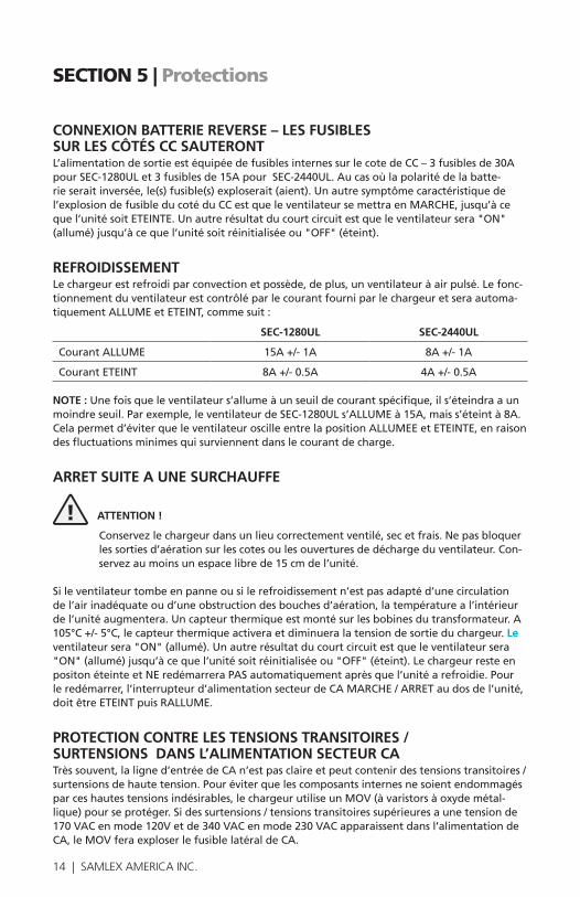
14 | SAMLEX AMERICA INC.
SECTION 5 | Protections
CONNEXION BATTERIE REVERSE – LES FUSIBLES SUR LES CÔTÉS CC SAUTERONT L’alimentationdesortieestéquipéedefusiblesinternessurlecotedeCC–3fusiblesde30ApourSEC-1280ULet3fusiblesde15ApourSEC-2440UL.Aucasoùlapolaritédelabatte-rieseraitinversée,le(s)fusible(s)exploserait(aient).Unautresymptômecaractéristiquedel’explosiondefusibleducotéduCCestqueleventilateursemettraenMARCHE,jusqu’àcequel’unitésoitETEINTE.Unautrerésultatducourtcircuitestqueleventilateursera"ON"(allumé)jusqu’àcequel’unitésoitréinitialiséeou"OFF"(éteint).
REFROIDISSEMENTLechargeurestrefroidiparconvectionetpossède,deplus,unventilateuràairpulsé.Lefonc-tionnementduventilateurestcontrôléparlecourantfourniparlechargeuretseraautoma-tiquementALLUMEetETEINT,commesuit:
SEC-1280UL SEC-2440UL
CourantALLUME 15A+/-1A 8A+/-1A
CourantETEINT 8A+/-0.5A 4A+/-0.5A
NOTE :Unefoisqueleventilateurs’allumeàunseuildecourantspécifique,ils’éteindraaunmoindreseuil.Parexemple,leventilateurdeSEC-1280ULs’ALLUMEà15A,maiss’éteintà8A.Celapermetd’éviterqueleventilateuroscilleentrelapositionALLUMEEetETEINTE,enraisondesfluctuationsminimesquisurviennentdanslecourantdecharge.
ARRET SUITE A UNE SURCHAUFFE
! ATTENTION !
Conservezlechargeurdansunlieucorrectementventilé,secetfrais.Nepasbloquerles sorties d’aération sur les cotes ou les ouvertures de décharge du ventilateur. Con-servez au moins un espace libre de 15 cm de l’unité.
Si le ventilateur tombe en panne ou si le refroidissement n’est pas adapté d’une circulation del’airinadéquateoud’uneobstructiondesbouchesd’aération,latempératureal’intérieurdel’unitéaugmentera.Uncapteurthermiqueestmontésurlesbobinesdutransformateur.A105°C+/-5°C,lecapteurthermiqueactiveraetdiminueralatensiondesortieduchargeur.Le ventilateursera"ON"(allumé). Un autre résultat du court circuit est que le ventilateur sera "ON"(allumé)jusqu’àcequel’unitésoitréinitialiséeou"OFF"(éteint).LechargeurresteenpositonéteinteetNEredémarreraPASautomatiquementaprèsquel’unitéarefroidie.Pourleredémarrer,l’interrupteurd’alimentationsecteurdeCAMARCHE/ARRETaudosdel’unité,doitêtreETEINTpuisRALLUME.
PROTECTION CONTRE LES TENSIONS TRANSITOIRES / SURTENSIONS DANS L’ALIMENTATION SECTEUR CA Trèssouvent,laligned’entréedeCAn’estpasclaireetpeutcontenirdestensionstransitoires/surtensionsdehautetension.Pouréviterquelescomposantsinternesnesoientendommagésparceshautestensionsindésirables,lechargeurutiliseunMOV(àvaristorsàoxydemétal-lique)pourseprotéger.Sidessurtensions/tensionstransitoiressupérieuresaunetensionde170VACenmode120Vetde340VACenmode230VACapparaissentdansl’alimentationdeCA,leMOVferaexploserlefusiblelatéraldeCA.

14 | SAMLEX AMERICA INC. SAMLEX AMERICA INC. | 15
SECTION 6 | Installation
DIMENSIONS D’INSTALLATION Les dimensions d’installation sont données ci-dessous. Les dimensions sont les mêmes pour SEC-1280UL and SEC-2440UL
SEC-1280-2440UL Top View Dimensions
2
244
381
350
5
75
2
75
200
244
97
9

16 | SAMLEX AMERICA INC.
SECTION 6 | Installation
EMPLACEMENT, MONTAGE ET SECURITÉLechargeurdoitêtreinstallédansunlieucorrectementventilé,secetfrais.Veuillezconsultezlasection«Précautionsimportantesdesécurité».Lechargeurpeutêtremontédemanièrehorizontaleouverticale.Lorsqu’ilestmontéverticalementsurunmurouunecloison,veuillezvousassurerquel’axedel’héliceduventilateuresthorizontal,c.a.dquel’ouvertureduventi-lateurestdisposéeversladroiteouverslagauche,maisNIverslebas,NIverslehaut.
AVERTISSEMENT !
Fixezl’unitéverticalementsurunesurfaceverticaleaveclessortiesduventilateurenhautouenbasn’estPASautorisé.Celaestdangereuxetpermetd’éviterlachuted’objetsdansl’unitéàtraverslagrilleduventilateur,lorsquel’ouvertureduventi-lateurestorientéeverslehaut.Sil’ouvertureduventilateurestorientéeverlebas,certainsdescomposantsendommagésencorechauds,peuventtomber.
CONNECTEURS DE SORTIELesconnecteursauxbornestubulairesouàcouronnesvisséessontutiliséspourlesbranche-mentsdesortie.Lediamètredutroutubulaireduconnecteurestde8mm(0.31pouces).Deuxconnecteursdesortiepositifs(1,2)sontfournispourêtreraccordésauxbornespositivesdes2banquesdebatteries.Unconnecteurcommun(3)estfournipourleraccordàlabornenégative.LataillefixedevisestM8.
COSSES DE BORNE POUR LA CONNEXION AU CHARGEUR Pourunbonbranchementlorsquevousutilisezdescâblestorsadés,pincez/soudezdescossesdeborneen«tête»d’épinglesurlaterminaisondescâblesdeCAduchargeurpourcon-necterlabatterie/d’autreschargesdeCC. 3piècesdecossesdebornedetype«têted’épingle»sontfournies:
• PourSEC-1280UL marcheraavecdescâblesAWG#2/35mm2wire
• PourSEC-2440UL marcheraavecdescâblesAWG#4/25mm2wire
CABLESAfind’évitertouteerreursdepolaritéetdedégâtséventuels,nejamaisutiliserdecâblesd’uneseulecouleur.Utilisezdescâblesisolésrougespourlesconnexionspositivesetdescâblesisolésnoirspourlesconnexionsnégatives.Lesdiamètresdecâblesrecommandéssontindiquésci-dessous(enfonctiond’unechutedetensionde2%).Lalongueurencm,concernelalongueurd’unepairedecâblespositifetnégatifdeCCdepuislechargeurdelabatterie/d’autres charges de CC.
Distance depuis la batterie SEC-1280UL SEC-2440UL
Jusqu’ à 15 cm AWG#2 AWG#8
15 à 25 cm AWG#1/0 AWG#6
25 à 50 cm AWG#3/0 AWG#4
TERMINAISON DES CABLESPourunbranchementsolide,lorsquevousutilisezdescâblesstandards,laterminaisondescâblesdoitsetermineraveclescossesentêted’épinglefournies.

16 | SAMLEX AMERICA INC. SAMLEX AMERICA INC. | 17
SECTION 7 | Preparer Le Chargeur Pour L'Utilisation
SELECTIONNER UNE TENSION D’ENTREE DE CA Lechargeurestpréréglépourfonctionneravecunetensiondel’entréedeCAde120VAC, 60Hz.Pourutiliserlechargeuravecunetensiond’entréedeCAde230VAC,50Hz,changezles réglages internes comme suit :
1.Retirezlaplaquelatéralequicontientl’entréeducordond’alimentation,endévissantles4visses.
2.Retirezlevoltmètreetl’ampèremètresurlaplaquecentraleenfaisantlevieraveclesbordsdesmètresavecuntournevisplatetenpoussantlesmètresverslehaut,depuislebasdelaplaque(ceux-cisontclipsés).Retirezlescâblesdeconnexionetmarquez-les.Notezlapolaritépourlesrebranchercorrectementparlasuite.LesbornesdesmètressontmarquéesPositive(+)etNégative(-).Lescâblesdel’ampèremètresontplusépaisqueceuxduvoltmètre,quieux,sontplusfins.
3.Faitesdoucementglisserlaplaquedecouverturecentrale.Notezetmarquezsonorientationpourla replacer correctement par la suite.
4.Localisezlabouclejaunedufilderaccordementaveclecâblefemelle.Danslesréglagesde 120VAC,cefilderaccordementcourt-circuitelesbrochesmalesverticalesmarquées“C“et“D“et“115V“.Tirezsurl’unedesextrémitésdecescâblesfemellespourdébrancherlecourtcircuitentre“C“et“D“.Isolezcetteextrémitéavecdiscotchisolant.L’unitéestdésormaisprêteafonctionnersousdu“230VAC“.
5.Laversion120VACdisposed’unfusiblede20AsoudesursoncotédeCA.Lorsqu’uneunitéde120VACestconvertieen230VAC,ilnyapasbesoinderemplacerlefusiblede20A.
6.RemplacezlaprisedeCAducordond’alimentationavecunepriseà3brochesadaptéeaufonc-tionnementdel’unitésous230VAC.
! ATTENTION !
Lanouvelleprisedoitcomporter3pôles,c.a.d.Ligne(L),Neutre(N)etMisealaterre.Le code couleur pour les conducteurs du cordon d’alimentation est :-Ligne(L)-Noir-Neutre(N)-Blanc- Mise à la terre - Vert
BRANCHEMENT DES BATTERIES OU AUTRES CHARGES DE CC Commemontresurlesschémas7,1et7,1ci-dessus,lasortieduchargeurpossèdeunebornenégativecommuneet2bornespositives,pourpouvoirbrancher2banquesdebatteries.Chaquebornepositivepossèdeunediodeinterneisolante,quifonctionnecommeisolantdebatterie.Siplusd’unebanquedebatteriesestbranchée,ellesserontchargéesenmêmetempsquel’alimentationdeCAdisponibleauchargeur(lecourantdechargemaximumde80ApourSEC-1280ULetde40ApourSEC-2440ULserarepartiparmilesbanquesbranchéesauxbatter-ies,enfonctiondel’étatdeleurdécharge).Aucasoul’alimentationdeCAtombaitenpanneous’iln’yavaitaucunesortiedepuislechargeur,lesdiodesisolanteséviterontlacharge/ladéchargedesbatteriesconnectéesauxbanques.
Dansuneseulebanquedebatterie,deuxouplusieursbatteriespeuventêtrebranchéesenparallèle,afind’augmenterleurscapacitésAH.Ellesserontdéchargéesetchargéescommeunebanquedebatterieunique.Danscecas,labanquedesbatteriesmultiplesbranchéeenparallèledoitêtreconsidéréecommeunebanqueuniqueetdoitêtrebranchéeàl’unedes2banquesduchargeur,telquemontrésurleschéma7.2pourunebanquede4batteries.Pourunechargecorrectedetouteslesbatteries,assurez-vousquelecâblepositif“A”duchargeursoitbranchéàlabornepositivedelapremièrebatterie(Batterie1)etquelecâblenégatif“B”soitbranchéàlabornenégativedeladernièrebatterie(batterie4).Celapermettraque:

18 | SAMLEX AMERICA INC.
• Larésistancedescâblesd’interconnexionsoitéquilibréeetquelesbatteriesindividuellesconnais-sent la même résistance en série.
• Touteslesbatteriesindividuellessoientchargéesaumêmecourantdechargeetsoientainsichargées au même niveau de charge.
• Aucunesdesbatteriesneconnaissed’étatdesurcharge.
LorsquevousbranchezunebatterieuniqueàuneautrechargeuniquedeCC,ellepuisseêtreconnectéeàunebornenégativecommuneouàl’unedes2bornespositives,telquemontrésurleschéma7,1.
CHARGER PLUS D’UNE BANQUE DE BATTERIES
! ATTENTION !
Lorsque vous chargez plus d’une banque de batterie à la fois en utilisant la charge en 3étapes,assurez-vousquel’étatdedéchargedesbatteriesdesbanquesestéquiva-lent.Siunebanqueestcomplètementdéchargéeetquel’autreestquasimentpleine,labanquepleinementchargéeserasujetteàunesurcharge,pendantquelechargeurdemeureenphase2(“Uo”Phase)pourchargerlabanquecomplètementdéchargée.
Si 2 banques de batteries doivent être chargées et qu’elles sont à des états de déchargedifférents,sélectionner“Batteriechargée”(chargementen2phases)grâceauxinterrupteursS1etS2,parmiles4interrupteursDIP(S1&S2sontdésactivés).Consultezlasection"RéglageduCommutateurDIPàlapage21".
SELECTIONNER LE TYPE DE BATTERIE ET LES PHASES DE CHARGELatensiondelaphasedemaintien3(phase“U”)etcelledelaphased’adsorption2(phase“Uo”)sontdifférentespourlesdiverstypesdebatteriesplomb-acide.
Lechargementen3phases(phase1,2et3)estrecommandelorsqu’unebatterieestchargéedemanièreautonome,etqu’elleestdéchargée(labatterien’aaucunechargeconnectéelorsqu’elleestencoursdecharge).
Lorsque le chargeur est utilise pour charger la batterie et pour à la fois fournir une charge externe,leniveaudetensiondelaphase2doitêtrerégléaumêmeniveauquealtensiondelaphase3,afind’évitertoutesurcharge.Sicelaestefficace,labatterieserachargéeen2phasesuniquement,enphase1et3.Celas’appliqueégalementlorsquedeuxbanquesdebatteriesontchargéessimultanémentetquelesbatteriesdesdeuxbanquessontàunstadededéchargedifférent.DeuxinterrupteursS1&S2parmiles4interrupteursDIPontétéfournisafindepouvoirsélectionnerletypedebatterieetpourmodifierlaphased’absorption2,lorsquedesbatterieschargées/deuxbanquesdebatterieauxétatsdechargedifférentssonten train d’être chargées. Les sélections suivantes peuvent être effectuées à l’aide des inter-rupteursDIPS1etS2:
SECTION 7 | Preparer Le Chargeur Pour L'Utilisation
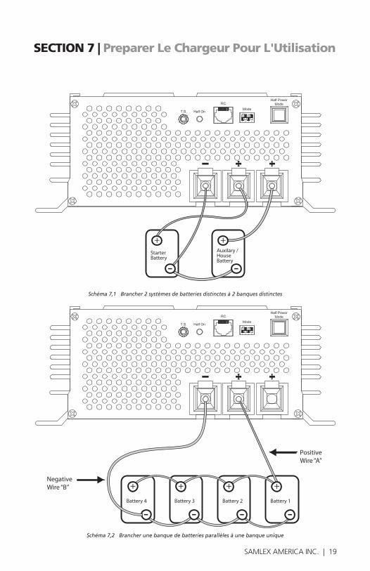
18 | SAMLEX AMERICA INC. SAMLEX AMERICA INC. | 19
SECTION 7 | Preparer Le Chargeur Pour L'Utilisation
StarterBattery
Auxilary /HouseBattery
Battery 4 Battery 3 Battery 2 Battery 1
Negative Wire “B”
Positive Wire “A”
Schéma 7,1 Brancher 2 systèmes de batteries distinctes à 2 banques distinctes
Schéma 7,2 Brancher une banque de batteries parallèles à une banque unique
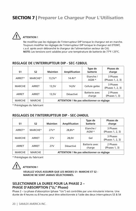
20 | SAMLEX AMERICA INC.
! ATTENTION !
Nemodifiezpaslesréglagesdel’interrupteurDIPlorsquelechargeurestenmarche.Toujoursmodifierlesréglagesdel’interrupteurDIPlorsquelechargeurestETEINT,c.a.d.aprèsavoirdébranchélechargeurdel’alimentationsecteurdeCA).NOTE:Lestensionssontvalablespourunetempératuredebatteriede77ºF/25ºC.
REGLAGE DE L’INTERRUPTEUR DIP - SEC-1280UL
S1 S2 Maintien AmplificationType de batterie
Phases de charge
ARRET* MARCHE* 13,5V* 14.4V*Etanche/AGM*
3Phases(Phases1,2,3)
MARCHE ARRET 13,5V 14,0V Cellule gelée3Phases
(Phases1,2,3)
ARRET ARRET 13,5V DésactivéBatterieavec
charge2Phases
(Phases1,3)
MARCHE MARCHE ATTENTION ! Ne pas sélectionner ce réglage
*Préréglagesdufabricant
REGLAGES DE l’INTERRUPTEUR DIP - SEC-2440UL
S1 S2 Maintien AmplificationType de batterie
Phases de charge
ARRET* MARCHE* 27V* 28,8V*Etanche/AGM*
3Phases(Phases1,2,3)
MARCHE ARRET 27V 28,0V Gel3Phases
(Phases1,2,3)
ARRET ARRET 27V DésactivéBatterieavec
charge2Phases
(Phases1,3)
MARCHE MARCHE ATTENTION ! Ne pas sélectionner ce réglage
*Préréglagesdufabricant
! ATTENTION !
VEUILLEZ VOUS ASSURER QUE LES MODES S1- MARCHE ET S2 - MARCHE NE SONT JAMAIS SÉLECTIONNÉS.
SELECTIONNER LA DUREE POUR LA PHASE 2 – PHASE D’ABSORPTION (“U0” Phase)Phase2–Laphased’absorption(phase“Uo”)estcontrôléeparuneminuterieinterne.Uneduréede4heuresou8heurespeutêtresélectionnéeàl’aidedesdeuxinterrupteursS3&S4
SECTION 7 | Preparer Le Chargeur Pour L'Utilisation
20 | SAMLEX AMERICA INC. SAMLEX AMERICA INC. | 21
SECTION 7 | Preparer Le Chargeur Pour L'Utilisation
del’ensembledes4interrupteursDIP(5).Demandezaufabricantdevotrebatteried’effectuerun réglage optimal. La valeur présélectionnée est 4 heures. Sélectionnez les durées comme suit :
Durée Interrupteur DIP S3 Interrupteur DIP S4 Type de Batterie
4heures* ARRET* MARCHE* Etanche/électrolyte
8 heures MARCHE ARRET Cellulegelée&AGM
Désactiver ARRET ARRET -
*Préréglagesdufabricant
! ATTENTION !
VEUILLEZ VOUS ASSURER QUE LES MODES S3 – MARCHE ET S4 – MARCHE NE SONT JAMAIS SÉLECTIONNÉS.
REDUCTION DE LA CAPACITE MAXIMALE DE CHARGE PAR DEUX POUR CHARGER CHARGE SURE DES BATTERIES A PLUS FAIBLES CAPACITES – MODE DEMI PUISSANCE Lesbatteriesnedoiventpasêtrechargéesàdetrèsfortscourants,afindeprolongerleurduréedevie.Saufsiapprouvéparlefabricant,lecourantdechargemaximaldoitêtrelimitéàapproximativementC/10(ouCestlacapacitéAhdelabatterieàuntauxhorairede20).Ainsi,auxcapacitésdecourantnominal(80ApourSEC-1280ULet40ApourSEC-2440UL),lacapacitéAhdelabatteriedevantêtrechargéeaveclechargeursera:
• 80Ax10=800AhpourSEC-1280UL
• 40Ax10=400AhpourSEC-2440UL
SiunebatterieàlacapacitéAhmoindre,estchargéeàuntauxdecourantmaximal,laduréede vie de la batterie sera certainement réduite.
Uneprovisionaétéeffectuéepourréduirelecourantdechargemaximumaenviron:40A+/-1ApourSEC-1280UL&20A+/-1ApourSEC-2440UL.Cemodeestdéfinicomme“Modededemipuissance”.Cemodepeutêtresélectionnéenpressantl’interrupteur“Modededemipuissance”(8).Unefoissélectionné,lesbatteriesauxplusfaiblescapacitéssuivantes,peuventêtrechargéesdemanièresureàuntauxdechargedeC/10:
• SEC-1280UL-400Ah
• SEC-2440UL-200Ah
COMPENSATION DE TEMPERATURE La tension des cellules de la batterie dépendent de la température des cellules à l’intérieur decelle-ci.Lescellulesontuncoefficientdetempératurenégative.Leursniveauxdetensionaugmentent lorsque la température est basse et diminue lorsque la température est élevée. Le coefficientdetempératurenégativeestde-2.5mV/ºF/celluleoude-15.0mV/ºF/6cellulespourunebatterie12Vou-30.0mV/ºF/12cellulespourunebatterie24V.

22 | SAMLEX AMERICA INC.
La batterie et les tensions du chargeur de batterie indiquent normalement une température de77ºF(25ºC).Ainsi,silatempératuredelabatterieestconsidérablementsupérieureouinferieurea77ºF,elleserasouschargéeousurchargée,saufsilechargeurdebatteriedisposed’une compensateur thermique.
SONDE DE TEMPERATURE TF-500 Cechargeurintègreunecompensationdelatempérature.Unesondedetempérature,modèleNo.TF-500(Schéma.7,3)estfourniàceteffet.
Schéma. 7,3. Capteur thermique Modèle No. TF-500
! ATTENTION !
Ce capteur thermique est relié et calibré pour chaque chargeur de batterie et ne doit pas être interverti avec les capteurs d’un autre chargeur de batterie.
Lecapteurthermiqueestlivréavecuncâblede5mètres.Ilpossèdeunepriseàsonextrémité.Branchezcettepriseàl’undesjacksmarquéTS(4)surlepanneauarrièreduchargeur.L’autreextrémitécomportelecapteurthermique.Encastrezcecapteurthermiquesurlapartielaté-rale de la batterie pour un transfert de température adéquat.
Lorsquelecapteurthermiqueestbranche,lestensionsaucoursdesphases2et3sontautomatiquementajustéesenfonctiondelatempératuredelabatterieetducoefficientdetempérature ci-dessus.
TELECOMMANDE DU PANNEAU, MODELE NO. 900-RC
Schéma 7,4 Télécommande du panneau, Modèle No. 900-RC
SECTION 7 | Preparer Le Chargeur Pour L'Utilisation
Plug TemperatureSensor Element
Remote Panel
Cable with plug

22 | SAMLEX AMERICA INC. SAMLEX AMERICA INC. | 23
SECTION 7 | Preparer Le Chargeur Pour L'Utilisation
Unetélécommandedupanneau,modèleNo.900-RCoptionnelle(Schéma8.1ci-dessus)peutêtrecommandée.Elleestlivréeavecuncâblemodulaireetdroitde10mètresdelong.Ilestbranchéàlatélécommandeparunjack(6).La télécommande du panneau peut être utilisée pour ALLUMER / ETEINDRE le chargeur et pour contrôler l’état de charge du chargeur à distance.
Veuillez consultez ce manuel pour en savoir plus sur la commande du panneau optionnelle 900-RC.
SECTION 8 | Fonctionnement ! CAUTION!
Coefficientdetempératurenégatif(CTN)thermistancessontutilisésensérieaveclecircuitd'entréeCApourlimiterdestrèsgrandpicdecourantd'appelétabliparlescondensa-teursducôtéd’entrée,quiagissentcommeuncourt-circuitpendantlepremierdemi-cycleaprèsquelechargeurest"ON"(allumé).Lorsquelechargeurest"ON"(allumé),CTNestàl'étatfroid,sarésistanceestélevée,donclepicdecourantd'appelestsuppriméauniveausécuritaire.Ilchauffetrèsrapidementetsarésistanceretombepresqueàzéro.Ilrestedansunétatchaufféainsiquelechargeurreste"ON"(allumé).Lorsquelechargeurest"OFF"(éteint),leCTNnécessiteenviron2à3minpourrefroidiretréinstallesarésistanceàunétathaut/froidspoursupprimerlepiclaprochainefoisquecelaserarequis.Lesprécautionssuivantesdoiventêtreprisespouréviterd'endommagerleCTNetaucircuitd'entrée:
• Nemettezpasenmarche"ON",éteignez"OFF"etallumez"ON"lechargeurensucces-sionrapide.Aprèsavoiréteintlechargeur,attendezaumoins5minutesavantderallumer"ON"pourpermettrelerefroidissementduCTN.
• Lorsquevousallumezlechargeurd’ungénérateur,permettezlegénérateurdeseréchaufferetdesestabiliserentensionavantd’allumer"ON"lechargeur.Silechargeurestenétat"ON"(allumé)etlegénérateurestdémarré,leshautestensionstransitoiresproduitsparlegénérateurlorsdudémarragepeuventendommagerleCTN.
ALLUMER / ETEINDRE LechargeurestALLUME/ETEINTal’aidedel’interrupteurMARCHE/ARRETdeCA(9)situésurlepanneauarrièredel’unité.L’interrupteurs’allumeenrougelorsqu’ilestenMARCHE.
INDICATION DE FONCTIONNEMENT NORMAL ET STATUT DE LA CHARGE Lorsquelechargeurestallumesansaucunecharge,leventilateurs’allumeramomentanémentpuis s’éteindra.
Levoltmètre(12)indiqueralatensionauxbornesduchargeur.L’ampèremètre(13)indiquerale courant puisé depuis le chargeur. Lorsqu’une batterie autonome est en cours de charge etqu’elleestpleinementchargée,lecourantavoisinera0A.Lorsquelechargeurestenlimitedecourantaucoursdelaphase1–phasedechargedemasse(phase“I”)oudephase2–phased’absorption(phase“UO”),lecourantindiquesera80ApourSEC-1280ULet40ApourSEC-2440A.

24 | SAMLEX AMERICA INC.
ALIMENTER D’AUTRES CHARGES DE CC Lechargeurpeutêtreutilisécommesourced’alimentationoucommeonduleurdeCC(sourced’alimentationininterrompuedeCC.Pourcesdeuxutilisations,veuillezd’abordmettrelesinterrupteursS1etS2enpositionéteinte,afinderéglerlechargeursurlemodechargeen2phases(Consultez"RéglageduCommutateurDIPàlapage21").
UTILISER LE CHARGEUR COMME SOURCE D’ALIMENTATION Afindel’utilisercommesourced’alimentation,débrancheztoutd’abordlachargedeCC.ConnectezlachargedeCCàlabornecommunenégativeetàl’unedesdeuxbornespositives.Assurez-vousquelecourantmaximumtireparlachargedeCCsoitinferieursauseuildecou-rantmaximumduchargeur.Allumezlechargeur,puislachargedeCC. Pourlefonctionnementdanscemode,réglezlescommutateursS1etS2decommutateurDIPnoteMode(7)à"OFF"(éteint)pourl’application"BatterieavecCharge".
UTILISER LE CHARGEUR COMME ONDULEUR DE CC DansunonduleurdeCC(sourced’alimentationsansinterruption),lechargeuralimentealafoislachargedeCCetlabatterie.Tantquel’alimentationdeCAverslechargeurestdisponibleetqueelchargeurfonctionnenormalement,lechargeurfourniraunechargedeCCetchargera/maintiendralabatterie.Aucasoul’alimentationdeCAdisparaissaitousilechargeurcessaitdefonctionner,labatteriealimenteraautomatiquementlachargedeCC.Desquel’alimentationdeCAverslechargeurestrestaurée,lachargeDCseradenouveaualimen-téeparlechargeuret,danslemêmetemps,labatterieserarechargée.
! ATTENTION !
FaitesensortequelasommeducouranttiréparlachargeCCetquelecourantsou-haitépourlachargedelabatteriesoitinférieursàlacapacitémaximumducourantdu chargeur.
PourutiliserunonduleurdeCC,veuilleztoutd’abord,ETEINDRElachargeCCetlabrancheràlabatterie.Ensuite,connectezlabatterieauchargeurcommeexpliquéci-dessus.Allumezlechargeur,puislachargeCC.Pourlefonctionnementdanscemode,réglezlescommutateursS1etS2decommutateurDIPnoteMode(7)à"OFF"(éteint)pourl’application"BatterieavecCharge".
SECTION 8 | Fonctionnement

24 | SAMLEX AMERICA INC. SAMLEX AMERICA INC. | 25
SECTION 9 | Resolution Des Problemes
Lessymptômesd’unfonctionnementanormaletlescausesetremèdesprobablessontdonnesdans les paragraphes suivants.
IL N Y A AUCUNE TENSION DE SORTIE. L’INTERRUPTEUR MARCHE / ARRET DE CA NE S’ALLUME PAS LORSQU’IL EST ENCLENCHE. LE VOLTMÈTRE RESTE IMMOBILE. (SUR LE PAN-NEAU DE COMMANDE, LA DEL VERTE SOUS « POWER » EST ÉTEINTE).
• Il n y a aucune tension d’entrée de CA dans la prise : vérifiezquel’alimentationdeCAestdis-ponibledansleréceptacledelaprisedeCAetqu’elleestALLUMEE.
• Le fusible latéral d’entrée de CA a explosé en raison de :Tensiond’entréeélevée:vérifiezquelatensiond’entréenominaleestde120VAC(étenduenormaleestentre108et132VAC).
• Tensions transitoires / surtensions de haute tension dans la ligne d’entrée de CA :vérifiezqueletensiond’entréedeCAestclaireetneprésentepasdetensionstransitoires/surtensionsdehautetension.Lestensionstransitoiresetsurtensionsd’entréesupérieuresà170VACferontexploserlefusiblelatéraldeCA.Utilisezuneconditionneurdetensionouunparasurtenseurs,sinécessaire.
• L’unité est défectueuse :silefusiblen’explosepasenraisondesdeuxraisonsci-dessus.
IL N Y A AUCUNE TENSION DE SORTIE. LE VOLTMÈTRE RESTE IMMOBILE ET L’INTERRUPTEUR MARCHE / ARRET DE CA S’ALLUME EN ROUGE (SUR LE PANNEAU DE COMMANDE, LA DEL ROUGE SOUS LA “PHASE I” EST ALLUMÉE, LA DEL VERTE SOUS “POWER” EST ALLUMÉE). LE VENTILATEUR EST ALLUME DE MANIÈRE CONTINUE.
• Le fusible latéral de sortie de CC a explosé :lefusiblelatéralexploserasilabatterieestbranchéeavecunepolaritéinversée.Assurez-vousdeconnecterlepolepositifdelabatterieauconnecteurpositifduchargeur(soitlabanque1ou2)etquelepolenégatifestconnecteauconnecteurnégatif(commun)duchargeur.Remplacezlesfusiblesavecdesfusiblesdemêmecalibre.
• La batterie / charge de CC a court circuité :vérifiezetréparezlecoutcircuit.Lechargeurresteraenpositonéteinte,s’ils’estarrêtéenraisonducourtcircuitetNEredémarreraPASautomatiquement.Pourleredémarrer.Eteignezl’interrupteurMARCHE/ARRETdel’entréedeCA,puisrallumez-le.
• Arrêt en raison d’une surchauffe :vérifiezqueleventilateurfonctionnenormalement,quelessorties d’aération ne sont pas obstruées et que la température ambiante n’est pas trop élevée. Le chargeurresteraenpositonéteinte,s’ils’estarrêtéenraisonducourtcircuitetNEredémarreraPASautomatiquement,mêmeunefoisquel’unitéarefroidie.Eteignezl’interrupteurMARCHE/ARRETdel’entréedeCA,puisrallumez-le.
• L’entrée de CA est réglée sur 230 VAC et est utilisée à 120 VAC :vérifiezlapositiondufilderac-cordementinterne,etréglezl’utilisationsur120VACou230VAC.Pouruneutilisationsous120VAC,lefilderaccordementdoitêtrebranchéetcourt-circuiterlespointsCetDsurlePCB.
LORSQUE LE CHARGEUR EST ALIMENTE ET UTILISE COMME SOURCE D’ALIMENTATION DE CC / ONDULEUR, LA TENSION DE SORTIE CHUTE LORSQUE LA CHARGE DE CC EST ACTIVÉE OU AUGMENTÉE.
• Lechargeurdoitsemettreenmodedelimitedecourant.Lachargetentedepuiserplusdecourantquelavaleurlimitedecourantduchargeur.80Apourunfonctionnementnormal&40A+/-1Apourle“modedemipuissance”pourSEC-1280ULet40Apourunfonctionnementnormal&20A+/-1Apourle“modedemipuissance”pourSEC-2440UL(lavaleurdelimitedecourantcorrespondauxAmpsdechargemaximumsspécifiés).Unefoisquelecourantatteintlavaleurdecourantlimite,lecircuitdecourantlimiteestactivéetlatensiondesortiechute.Certaineschargescommelesmoteurs,compresseurs,lampesincandescentes,lampeshalogènes,élémentsdechauffage,relais,bobines,condensateursetc.puisentuncourantd’appel/dedémarragetrèsélevéoulecourantdefonctionnementmaximumdelachargeestinferieuralavaleurdecourantlimiteduchargeur.Nepasutiliserunechargequipuiseplusde80A(40A+/-1Apour“modedemi

26 | SAMLEX AMERICA INC.
puissance”)pourSEC-1280ULouplusde40A(20A+/-1Apourle“modedemipuissance”) pourSEC-2440UL.Unefoisquelecourantdechargeestinferieurauxvaleurslimitesci-dessus, lechargeurrécupèreraautomatiquement.
LA BATTERIE EST EN ÉTAT DE SURCHARGE / SURCHAUFFE OU CONNAÎT UNE PERTE D’EAU OU ÉBULLITION
• Une charge externe est connectée a la batterie lorsque celle-ci est en cours de charge : la charge en3phasesestrecommandépourchargerlesbatteriesautonomesetdéchargées(aucunechargen’estconnectéealabatterielorsqu’elleestencoursdecharge).Siunechargeestégalementconnectéesimultanément,unepartieducourantdesortieduchargeurseradétournéverscettecharge.Ainsi,lechargeurpeutresterverrouilléenphase2,silecouranttiréparlachargeestsupérieur à la valeur présélectionnée du seuil de courant. Cela détermine le passage de la phase 2 à la phase 3 et provoquera une surcharge ou une perte d’électrolyte.
Pourchangerunebatterielorsquelachargeestégalementconnectéesimultanément.Latensiondephase2devraêtrelamêmequecelledelaphase3.Sélectionnez«Batteriechargée»al’aidedesinterrupteursDIP«Mode»(7)–lirelasection7sous«Sélectionnerletypedebatterieetlesphasesdechargement».
• Deuxbanquesdebatteriessontchargéesetlesbatteriesdesdeuxbanquessontaunétatdedécharge différent : lorsque vous chargez plus d’une banque de batteries en même temps en utilisantlachargeen3phases,assurez-vousquel’étatdedéchargedesbatteriesdesbanquesestéquivalent.Siunebanqueestcomplètementdéchargéeetquel’autreestquasimentpleine,labanquepleinementchargéeserasujetteàunesurcharge,pendantquelechargeurdemeureenphase2(“Uo”Phase)pourchargerlabanquecomplètementdéchargée.
Si2banquesdebatteriesdoiventêtrechargéesetqu’ellessontàdesétatsdedéchargedifférents,sélectionner“Batteriechargée”(chargementen2phases)grâceauxinterrupteursS1etS2,parmiles4interrupteursDIP(S1&S2sontdésactivés).Consultezlasection“RéglageduCommutateurDIPàlapage 21”.
• Courant de charge très élevé pour batterie a faible capacité Ah :letauxdechargedoitêtrenor-malementlimitéaC/10,saufsispécifiédifféremmentparlefabricantdevotrebatterie.Untauxdechargetrèsélevépeutprovoqueruneréductiondelatensiondecharge,lorsqueledégage-mentgazeuxdébuteetpeutcauseruneforteaugmentationdestempératures,laperted’eauetl’ébullition de la batterie.
LA BATTERIE PREND ÉNORMÉMENT DE TEMPS À SE RECHARGER COMPLÈTEMENT OU LORSQUE LE CHARGEUR EST EN MARCHE ET EST UTILISE COMME FOURNISSEUR DE CC / ONDULEUR. LA TENSION DE SORTIE CHUTE A UN FAIBLE NIVEAU DE COURANT DE CHARGE CC.
• L’unité est en “mode demi puissance” :(DELverte(8)situéedanslecoininferieurgauchedupanneaufrontaldel’unitéestallumée).Lorsquelemodeestsélectionné,lecourantdechargemaximumseraautomatiquementréduita40A+/-1ApourSEC-1280ULet20A+/-1Apour SEC-2440UL.Ainsi,letempsdechargeserapluslong.Désactivezle“modedemipuissance”, si la charge de la pleine capacité de la batterie est requise.
SECTION 9 | Resolution Des Problemes
26 | SAMLEX AMERICA INC. SAMLEX AMERICA INC. | 27
SECTION 10 | Calibration Des Fusibles Internes
LescotésCAetCCdisposentdefusibles.
LefusibleducotéCAestsituésurlePCBF1àl’intérieurdel’unité.Ilestévaluéà250V,20A,temporisé(Taille6.3mmx32mm,spirale).
LesfusiblesducotéCCsontsituésàl’intérieurdel’unité.Pouraccéderàcesfusibles,retirezlaplaquesupérieure.Cesontdesfusiblesalame,detypeautomobile(parexemple,“Littelfuse”,detypeATO)estcalibrédelamanièresuivante:
SEC-1280UL 3pièces,chacunecalibréeà32V,30A
SEC-2440UL 3pièces,chacunecalibréeà32V,15A

28 | SAMLEX AMERICA INC.
SECTION 11 | Spécificités
PARAMETRE SEC-1280UL SEC-2440UL
TENSIOND'ENTRÉENOMINALE Préréglages du fabricant
En changeant le cavalier interne
120 VAC, 50 /60 Hz(108 à 132 VAC)
230 VAC, 50 / 60 Hz(207 à 253 VAC)
COURANTD'ENTRÉEA une tension d’entrée de 120 VACA une tension d’entrée de 230 VAC
15.9A8.6A
15.3A8.3A
TENSIONDESORTIEMasse “phase I ”
Absorption “ phase Uo”*Maintien “phase U”*
13.5V +/-0.05V14V / 14.4V +/-0.05V
13.5V +/- 0.05V
27.0V +/- 0.05V28V / 28.8V +/- 0.05V
27.0V +/- 0.05V
COURANTDECHARGEDEMASSEMAXIMUM,I
Fonctionnement normalMode demi puissance
80A40A +/-1A
40A20A +/- 1A
SEUILDECOURANT POURCHANGEMENT
De maintien “U” à amplification “Uo”D’amplification “Uo” à maintien “U”
15A +/-1A8A +/-0.5A
8A +/-1A4A +/-0.5A
DURÉEDEL’ABSORPTION/ PHASED’AMPLIFICATION
4 Heures or 8 Heures(Sélectionnable avec l’interrupteur)
CAPACITÉMAXIMUMDELABATTERIE 800 Ah 400 Ah
COMPENSATIONDELATEMPÉRATURE Oui. Avec sonde de température TF-500
TÉLÉCOMMANDEDUPANNEAU(OPTIONNEL)
Oui. Model 900-RC
REFROIDISSEMENT Charge contrôlée par ventilateur –
MARCHE à 15A ± 1A ARRET à 8A ± 0.5A
Charge contrôlée par ventilateur –
MARCHE à 8A ± 1A ARRET à 4A ± 0.5A
PROTECTIONS Surcharge
Court circuitPolarité inversée
Surchauffe
OUIOUIOUIOUI
BANQUESDESORTIE 2
CONNECTEURSDESORTIE Bornes a trous tubulaires (8 mm de diamètre) et vis de réglage - M8
ETENDUEDELATEMPÉRATUREDEFONCTIONNEMENT
0˚ – 40˚C
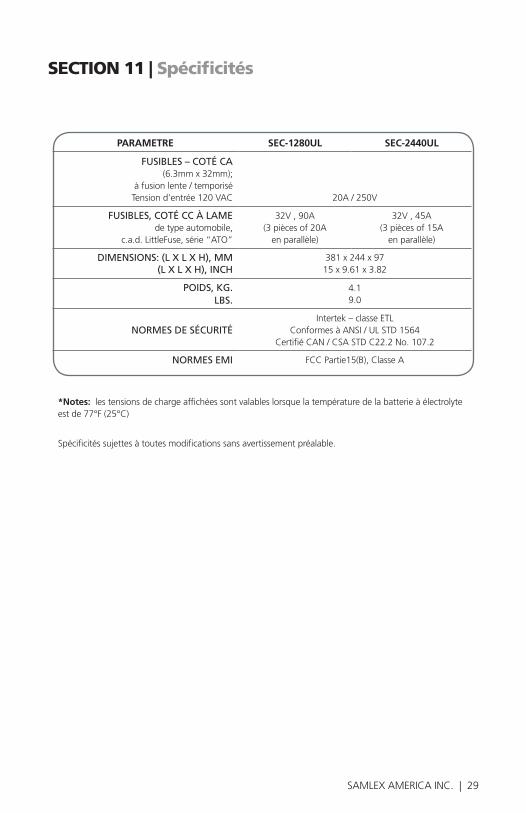
28 | SAMLEX AMERICA INC. SAMLEX AMERICA INC. | 29
SECTION 11 | Spécificités
PARAMETRE SEC-1280UL SEC-2440UL
FUSIBLES–COTÉCA (6.3mm x 32mm);
à fusion lente / temporisé Tension d’entrée 120 VAC 20A / 250V
FUSIBLES,COTÉCCÀLAMEde type automobile,
c.a.d. LittleFuse, série “ATO”
32V , 90A(3 pièces of 20A
en parallèle)
32V , 45A(3 pièces of 15A
en parallèle)
DIMENSIONS:(LXLXH),MM(LXLXH),INCH
381 x 244 x 9715 x 9.61 x 3.82
POIDS,KG.LBS.
4.19.0
NORMESDESÉCURITÉIntertek – classe ETL
Conformes à ANSI / UL STD 1564Certifié CAN / CSA STD C22.2 No. 107.2
NORMESEMI FCC Partie15(B), Classe A
*Notes: les tensions de charge affichées sont valables lorsque la température de la batterie à électrolyte est de 77°F (25°C)
Spécificités sujettes à toutes modifications sans avertissement préalable.

30 | SAMLEX AMERICA INC.
SECTION 12 | Garantie
GARANTIE LIMITEE SOUS 2 ANS
SEC-1280UL,SEC-2440UL,fabriquésparSamlexAmerica,Inc.(le«Garant»)sontgarantisêtrenondéfectueuxdanslaconceptionetdanslesmatériaux,moyennantuneutilisationetunservicenormaux.Lapériodedegarantieestde2anspourlesEtats-UnisetleCanada,etprendeffetlejourdel’achatparl’utilisateur(«l’Acheteur»).
LagarantiehorsdesEtatsUnisetduCanadaestlimitéeà6mois.Pouruneréclamationconcernantlagarantie,l’Acheteurdevracontacterlepointdeventeoul’achataétéeffectuéafind’obtenirunNumérod’AutorisationpourleRetour.
Lapièceoul’unitédéfectueusedevraêtreretournéeauxfraisdel’acheteuraupointdeventeagrée.Unedéclarationécritedécrivantlanaturedudéfaut,ladateetlelieud’achatainsiquelenom,l’adresseetlenumérodetéléphonedel’Acheteurdevrontégalementêtrerenseignés.
Sial’examinationdelademandeparleGarant,ledéfautestréellementlerésultatd’unmatériauoud’unassemblagedéfectueux,l’équipementseraréparéouremplacégratuitementetrenvoyéal’AcheteurauxfraisduGarant.(Etats-UnisetCanadauniquement).
Aucunremboursementduprixd’achatneseraaccordeal’Acheteur,saufsileGarantestincapablederemédieraudéfautaprèsavoireuplusieursoccasiondelefaire.LeservicedegarantiedoitêtreeffectueuniquementparleGarant.Toutetentativesderemédieraudéfautparquelqu’und’autrequeleGarantrendentcettegarantienulleetsanseffet.Iln’existeaucunegarantieconcer-nant les défauts ou dommages causés par une installation défectueuse ou ina-daptée,parunabusouunemauvaiseutilisationdel’équipement,ycompris,uneexpositionexcessivealachaleur,ausel,auxéclaboussuresd’eaufraicheou a l’immersion dans l’eau.
Aucuneautregarantieexpressn’estaccordéeetiln’existeaucunesgarantiesqui s’étendent au delà des conditions décrites par la présente. Cette garan-tieestlaseulegarantievalableetreconnueparleGarant,etprédominesurd’autresgarantieimplicites,ycomprislesgarantiesimplicitesliéesalagar-antiedequalitémarchande,al’usagedesobjectifshabituelspourlesquels

30 | SAMLEX AMERICA INC. SAMLEX AMERICA INC. | 31
SECTION 12 | Garantie
detellesmarchandisessontutilisées,oul’usagepourunobjectifparticulier,outoutesautresobligationsdelapartduGarantoudesesemployésetreprésentants.
IlnedoitpasexisterderesponsabilitéouautredelapartduGrantoudessesemployésetreprésentants,encequiconcernelesblessurescorporelles,oulesdommagesdepersonneapersonne,oulesdégâtssurunepropriété,oulapertederevenusoudebénéfices,ouautresdommagescollatéraux,pouvantêtre rapportés comme ayant survenus au cours de l’utilisation ou de la vente dumatériel,ycompristousdisfonctionnementsouéchecsdumatériel,ouunepartiedecelui-ci.LeGarantn’assumeaucuneresponsabilitéconcernanttoutessortes de dommages accidentels ou indirects.
Samlex America Inc. (le « Garant »)www.samlexamerica.com

InformationContact
Numéros gratuitsTel : 1 800 561 5885Fax : 1 888 814 5210
Numéros locauxTel : 604 525 3836Fax : 604 525 5221
Site internetwww.samlexamerica.com
Entrepôt USA Kent, WA
Entrepôt CanadaDelta, BC
Adresse email pour passer commande
11001-SEC-1280-2440UL-0616-FR