switchgear type 8dj20 up to 24 kv, gas-insulated type 8dj20 up to 24 kv, gas-insulated · siemens ha...
TRANSCRIPT

www.siemens.com/energy
Switchgear Type 8DJ20
up to 24 kV, Gas-Insulated
Medium-Voltage Switchgear
Catalog HA 45.31 · 2008

Switchgear Type 8DJ20 up to 24 kV, Gas-Insulated · Siemens HA 45.31 · 20082
8DJ20 switchgear is a factory-assembled, type-tested, metal-enclosed switchgear for indoorinstallation.
Typical uses
8DJ20 switchgear is used forpower distribution in substations– even under severe environmen-tal conditions, such as:
• Industrial environments
• Damp, sandy or dusty areas
• Simple outdoor substations
Main uses
• Compact substations
• Compact transformer substations,e. g. for wind power stations
• Garage and vault substations
• Underground and underfloorsubstations
• Sidewalk substations, e.g.containing switchgear with avery small overall width – inparticular the basic versionsof schemes 10, 32 and 71 –in conurbations
• Substations with control aisle
Technology
• Switchgear design with up to5 feeders
• Maintenance-free
• Climate-independent
• Partition class: PM(metallic partition)
• Three-pole primary enclosure,metal-enclosed
• Insulating gas SF6
• Welded switchgear vessel with-out seals, made of stainlesssteel, with welded-in bushingsfor electrical connections andmechanical components
• Three-position switch-discon-nector with load-break andmake-proof earthing function
• Cable connection forbushings with outside cone
• Connection with cable plugs– In ring-main feeders with
bolted contact (M16)– In transformer feeders with
plug-in contact
• Option: Connection withconventional sealing ends
– For thermoplastic-insulatedcables via elbow adapterAKE 20/630 (make Siemens)
– For paper-insulated mass-im-pregnated cables via commer-cially available adapter systems
• Easy installation
Personal safety
• Safe-to-touch and hermetically-sealed primary enclosure
• HV HRC fuses and cable sealingends are only accessible whenoutgoing feeders are earthed
• Operation only possible whenenclosure is closed
• Logical mechanical interlocking
• Capacitive voltage detectingsystem to verify safe isolationfrom supply
• Feeder earthing by means ofmake-proof earthing switches
Security of operation
• Hermetically-sealed primaryenclosure independent of en-vironmental effects such aspollution, humidity and smallanimals – sealed for life:
– Welded switchgear vessel– Welded-in bushings and
operating mechanism
• Operating mechanism partsmaintenance-free(IEC 62 271-1/VDE 0671-1)
• Operating mechanisms ofswitching devices located out-side the switchgear vessel(primary enclosure)
• Switchgear interlocking systemwith logical mechanical inter-locks
Cost-efficiency
Extremely low “life-cycle costs”throughout the entire productservice life as a result of:
• Maintenance-free concept
• Climatic independence
• Minimum space requirements
• Maximum availability
Standards
see page 21
Technical Data
Electrical data, filling pressure, temperature 4
Application, Requirements
Features, typical use 2 and 3
Product Range
Equipment features 4Product range overview, schemes 5
Design
Panel design 6
Dimensions
Switchgear 10 to 13Floor openings, fixing points 14 and 15Examples for cable connection 16
Designs, Special Designs
LV compartment, outdoor enclosures 18 to 20
Standards, Notes
Standards, specifications,guidelines, classification 21 to 23
Shipping
Types of transport, transport data 17
Components
Three-position switch-disconnector,operating mechanisms 7HV HRC fuse assembly, secondaryequipment, pressure absorber system 8Cable connection 9
For further information, please refer to
• Catalog HA 40.1:Switchgear Types 8DJ and 8DH, General Part
• HA 45.31/41.11:Supplements to Switchgear Types 8DJ and 8DH
Invalid: Catalog HA 45.31 · 2006
The products and systems described in this catalogare manufactured and sold according to a certifiedquality and environmental management system(acc. to ISO 9001 and ISO 14001).(DQS Certificate Reg. No. DQS 003473 QM UM).The certificate is accepted in all IQNet countries.
Contents Application, RequirementsFeatures
© Siemens AG 2008
Page

Switchgear Type 8DJ20 up to 24 kV, Gas-Insulated · Siemens HA 45.31 · 2008 3
Our product range extends fromswitchgear installed in a radialtransformer panel (individualpanel) to switchgear with 5feeders, consisting of
• Ring-main feeders
• Transformer feeders withHV HRC fuse assemblies
• Circuit-breaker feeders (forthe complete product rangesee Supplements to CatalogsHA 45.31/41.11 – 2006)
The switchgear is available inthree overall heights:
• 1200 mm(with low subframe)
• 1400 mm and 1760 mm(with high subframe)
These overall heights cover allareas of application, from com-pact substations to switchgearrooms with control aisle.
Basic design
• Manual operating mechanism
• Transformer cable connectionat the front (standard)
• With logical mechanical inter-locks
• With ready-for-service indicator
• With capacitive voltage de-tecting system at the ring-main feeders
Options (others on request)
• Capacitive voltage detectingsystem at the transformerfeeders
• Motor operating mechanismsfor the three-position switch-disconnectors
• Auxiliary switch for three-posi-tion switch-disconnector andmake-proof earthing switch
• Short-circuit indicator withbuilt-in housing
• Surge arresters for ring-mainfeeders
• Shunt releases for transformerfeeders
• Secondary equipment forremote operation or remoteindication, e.g. with local-remote switch in the case ofmotor operating mechanismsor ”tripped signal” in the caseof transformer feeders
• Locking devices
• Closing lock-out
• De-earthing lock-out
• Cable clamps
Radial transformerpanel
1 transformer feeder1 radial cable connection
Scheme 01
Ring-main/transformer block
2 ring-main feeders1 transformer feeder
Scheme 10
Ring-main/transformer block
3 ring-main feeders2 transformer feeders
Scheme 82
R-HA
45-0
99ce
ps
R-HA
45-1
00b
eps
R-HA
45-1
01ce
ps
R-HA
45-0
86ce
ps 8DJ20 switchgear ina compact substation
Typical useFeatures
Application

Switchgear Type 8DJ20 up to 24 kV, Gas-Insulated · Siemens HA 45.31 · 20084
• Basic equipment
° Additional equipment(option), furtheradditional equipmenton request
x Notapplicable
– Not avail-able
Equipment
Manual operating mechanism forthree-position switch-disconnector:
– As spring-operated mechanism– As spring-operat./stored-energy mech.
Motor operating mechanism forthree-position switch-disconnector
Interlock for cable compartmentcover
Cable compartment cover lockedin place/screwed on
Cable bracket 2) in ring-main and cablefeeders, cable routing downwards
Cable bracket in transformer feeder:For cable routing
– Downwards (standard), f. cable elb. plugsor
– Downwards, for straight cable plugsor
– To the rear, for cable elbow plugs
Low-voltage terminals in theoperating mechanism(option for secondary equipment)
Shunt release
Auxiliary switch for– Switch-disconnector
CLOSED/OPEN: 1 NO + 2 NC– EARTHING CLOSED/OPEN:
1 NO + 1 NC
Locking device forthree-position switch-disconnector
Short-circuit or earth-fault indicator
– Wiring at the indicator(standard)
– Wiring to terminal (option)
De-earthing lock-out formake-proof earthing switchin transformer feeder
Closing lock-out forthree-position switch-disconnector
Double cable connection for
– Overall height of switchgear 1200 mm– Overall height of switchgear 1400 mm– Overall height of switchgear 1760 mm
Surge arrester for
– Overall height of switchgear 1200 mm– Overall height of switchgear 1400 mm– Overall height of switchgear 1760 mm
Cable clamps for cable fixing
– Supplied separately– Preassembled (option)
Radial cable
connecti
on, pan
elK(E
) for sc
heme 21
(with
additio
nalea
rthing sw
itch)
Radial cable
connecti
on, pan
elK fo
r schem
e 02
(with
out earth
ing switc
h)
Ring-m
ainfe
eders
panel
RK
Transfo
rmer fe
eder
panel
1T insc
heme 01
Tran
sform
er
feed
ers
pane
lT
1) According to some national requirements, higher values of therated short-duration power-frequency withstand voltageavailable for Ik = 20 kA with:– 42 kV for phase-to-phase, phase-to-earth and open contact
gap as well as– 48 kV across the isolating distance
Higher values of the rated lightning impulse withstand voltage:– 95 kV for phase-to-phase, phase-to-earth and open contact
gap as well as– 110 kV across the isolating distance
2) For overall height of switchgear 1200 mm:Cable bracket below the feeder
3) Cable fixing by customer(the switchgear is supplied without cable bracket)
4) In case of scheme 01 the cable compartment cover is bolted.The transformer connection is effected via the bushingsarranged underneath the switchgear vessel. The transformerfeeder is earthed by the three-position switch
5) Temperature range, reduced normal currents at ambient airtemperatures > + 40 °C
6) Surge arrester type RDA with RICS (Tyco Electronics) notpossible for a height of 1200 mm
o. r. = on request
•–
xx
•–
–•
–•
– x ° ° °• – • • •
– • – – –
• • • • x
x
x
x
x
x
x
x
x
x
x
•
without3)
•
•
without3)
• – • • •
– – – ° °
°° x
x
°°
°°
°°
° x ° ° °
°°
°°
°°
–
–
–
–
° x x x 4) °– x ° – –
°°°
°°°
°°°
xxx
xxx
–
°°
–
°°
o. r. 6)
°°
xxx
xxx
°°
°°
°°
°– °°
Rated voltage Ur kV 7.2 12 15 17.5 24
Rated insulation level
Rated short-duration kVpower-frequencywithstand voltage Ud
20 28 1) 36 38 50
Rated lightning impulse kVwithstand voltage Up
60 75 1) 95 95 125
Rated frequency fr 50/60 Hz
Rated normal current Ir
for ring-main feeders 400 or 630 A
for transformer feedersdepending on theHV HRC fuse link
200 A
for schemes 01 and 21depending on theHV HRC fuse link
200 A
Rated short-timewithstand current Ik
at 1 s kAkAkA
–2025
–2025
–2025
162025
1620–
at 3 s (option) kA 20 20 20 20 20
Rated peak kAwithstand current Ip kA
kA
–5063
–5063
–5063
405063
4050–
Rated short-circuitmaking current Ima
for transformer feeders kA 25 25 25 25 25
for ring-main feeders kAkAkA
–5063
–5063
–5063
405063
4050–
Ambient air temperature T(operating conditions acc. toIEC 62 271-200/Clause 2 orIEC 62 271-1)
– Without secondary equipment– With secondary equipment,
class “Minus 5 indoor”
- 40 to + 70 °C 5)
- 5 to 55 °C 5)
Pressure values at 20 °Cfor the insulation:
Rated filling level pre 1500 hPa (absolute)
Minimum functional level pme 1300 hPA (absolute)
Technical Data, Product Range
Electrical data, temperature, filling pressure Equipment features of panels

Switchgear Type 8DJ20 up to 24 kV, Gas-Insulated · Siemens HA 45.31 · 2008 5
K Radial cableconnection asinfeed
K(E) Radial cableconnection, K asK(E) with make-proofearthing switch
Radial transformer panels
Scheme 01 * 1 transformer feeder,1 radial cable connection
(Abbreviation 1T)
510 775 120014001760
140160200
Radial panel
Scheme 02 1 ring-main feeder withradial cable connection
(Abbreviation 1RK)
710 775 120014001760
150170210
Block versions, consisting of ring-main and transformer feeders (with HV HRC fuse assembly)
Scheme 10 * 2 ring-main feeders,1 transformer feeder
(Abbreviations 2RK+1T)
1060 775 120014001760
280300340
Scheme 71 * 3 ring-main feeders,1 transformer feeder
(Abbreviations 3RK+1T)
1410 775 120014001760
340360400
Scheme 81 * 2 ring-main feeders,2 transformer feeders
(Abbreviations 2RK+2T)
1410 775 120014001760
400420460
Block versions, consisting of ring-main feeders (without HV HRC fuse assembly)
Scheme 11 2 ring-main feeders
(Abbreviation 2RK)
710 775 120014001760
160170210
Scheme 70 * 4 ring-main feeders
(Abbreviation 4RK)
1410 775 120014001760
280300340
Scheme
Components shown in dottedlines can be used optionally.
Overall dimensions Net 1)
weightapprox.
kg
Width
mm
Depth2)3)mm
Height
mm
Scheme
Components shown in dottedlines can be used optionally.
Overall dimensions Net 1)
weightapprox.
kg
Width
mm
Depth2)3)
mm
Height
mm
Scheme 21 1 radial cable connection,1 transformer feeder
(Abbreviations 1K(E)+1T)
710 775 120014001760
200210250
Scheme 20 1 ring-main feeder,1 transformer feeder
(Abbreviations 1RK+1T)
710 775 120014001760
200210250
Scheme 72 4 ring-main feeders,1 transformer feeder
(Abbreviations 4RK+1T)
1760 775 120014001760
420440480
Scheme 82 3 ring-main feeders,2 transformer feeders
(Abbreviations 3RK+2T)
1760 775 120014001760
470500540
Scheme 84 5 ring-main feeders
(Abbreviation 5RK)
1760 775 120014001760
350380420
Scheme 32 * 3 ring-main feeders
(Abbreviation 3RK)
1060 775 120014001760
210230270
1) Depending on the relevant equipment, e.g. motor operating mechanism
2) Additional wall distance required: W 15 mm
3) For cable routing of transformer cables downwards
* Scheme is also suitable for outdoor enclosure (see pages 18 and 19)
Abbreviations:
RK = Ring-main feeder K = Cable feeder T = Transformer feeder
K(E) = Cable feeder for radial cable connection with make-proof earthing switch
�
����
����
��
�
�
����
����
���
�
�� �
����
����
���
�
�� ���
����
����
���
�
�� ��� ��
����
����
���
�
�� ����
����
����
���
�
�� ��
����
����
���
�
�� ���� �� �� ���� �� ��
����
����
���
� ��
����
����
��
�� ����
����
����
���
�
�� ���� ��
����
����
���
�
�� ��� �� ��
����
����
���
�
���
����
����
���
�
�����
Product range overview, schemes
Product Range

Switchgear Type 8DJ20 up to 24 kV, Gas-Insulated · Siemens HA 45.31 · 20086
1 Niche for customer-side low-voltage equipment
2 Feeder designation label
Position indicatorsin the ring-main feeder:
3 Load-break function ”CLOSED – OPEN”4 Earthing function ”OPEN – EARTHED”
5 Rating and type plate
6 Ready-for-service indicator
7 Mimic diagram
8 Short-circuit/earth-fault indicator (option)
9 Sockets for voltage detecting system
10 Interlock of the cable compartment cover
11 HV HRC fuse assembly, cover removed
12 Handle for replacing the HV HRC fuse link
13 Interlock for HV HRC fuse assembly
Position indicatorsin the transformer feeder:
14 Earthing function ”OPEN – EARTHED”15 Load-break function ”CLOSED – OPEN”
with ”HV HRC fuse tripped” or ”shunt releasetripped”, where applicable
16 Locking device(option for three-position switch-disconnector)
17 Manual operation for the mechanism ofthe earthing function
OptionCable connection for cable elbowplugs, cable routing to the rear(cable fixing by customer)
18 Manual operation for the mechanism ofthe load-break function
19 Switchgear vessel, filled with gas
20 Connecting bar to cable connection
21 Arrangement of cable connections
22 Cable compartment
23 Cable bracket
24 Cable (not included in the scope of supply)
25 Cover of the HV HRC fuse compartment
26 Connecting bar to the bushingsfor the HV HRC fuse
27 Three-position switch-disconnector
28 Spring-operated/stored-energy mechanism
29 Bushing as interface type “A” forcable plug with plug-in contactOption: Bushing as interface type “C”for cable plug with bolted contact (M16)
30 Option: Cable elbow plug withplug-in contact
31 Cable compartment cover
32 M12 earthing connection
33 Spring-operated mechanism
34 Bushing as interface type “C“ for cableplug with bolted contact (M16)
35 Option: Cable T-plug with bolted contact
36 Pressure relief device
37 Option: Straight cable plug withplug-in contact
38 Option: Low-voltage compartment
����
����
��
�
������
�
�
�
�
�
�
�
�
�
��
��
��
��
��
��
��
�
�
��
��
��
��
��
��
��
��
�
��
�
��
��
��
��
��
��
��
��
��
��
��
��
��
� ��
��
� �
����
���
���
��
��
��
��
��
��
����
���
����
��
��
��
��
��
��
��
Ring-main/transformer block
StandardCable connection for cable elbow plugs(option: for cable T-plugs),cable routing downwards
Scheme 10
Transformer feeder
Section A-A
Cable connection with bolted contact (M16):– For cable T-plug or cable elbow plug– For conventional cable sealing ends via
elbow adapter AKE 20/630
OptionCable connection forstraight cable plugs,cable routing downwards
Ring-main feeder
Section B-B
Personal safety
All feeder-related covers can only beopened if the associated three-positionswitch-disconnector has been switched tothe “EARTHED” position.
Design
Panel design (example)

Switchgear Type 8DJ20 up to 24 kV, Gas-Insulated · Siemens HA 45.31 · 2008 7
Three-positionswitch-disconnector
The switching device usedis the proven three-positionswitch-disconnector
Functions
• Load-break function
• Earthing function withshort-circuit making capacity
• Switch positionsCLOSED – OPEN – EARTHED
Operating mechanisms
The three-position switch-disconnector is operated fromthe switchgear front via
Detachable lever mechanism(standard)
• Spring-operated mechanism– With ”spring-operated
CLOSED” and ”spring-oper-ated OPEN” for installationin ring-main feeders
• Spring-operated/stored-energy mechanism
– With ”spring-operatedCLOSED” and ”spring-oper-ated OPEN” for installationin transformer feeders
– With an additional energystore for the function ”stored-energy OPEN” after trippingby the HV HRC fuse (strikertripping) or by the shuntrelease
Options
• Motor operating mechanismfor switch-disconnector
• Rotary operating mechanism
• Locking devices
• Auxiliary contacts for three-position switch-disconnectorand make-proof earthingswitch
• Shunt release for transformerfeeders
• Closing lock-out for ring-main feeders
• De-earthing lock-out fortransformer feeders
• Different operating levers 1) forthe operating mechanisms ofthe switch-disconnector and ofthe make-proof earthing switch
Three-position switch-disconnector
R-HA
45-1
02ep
s
Operating mechanisms
Switchgear vessel of aring-main/transformerblock, scheme 10(rear view)
1 Three-position switch-disconnector in thetransformer feeder
2 Three-position switch-disconnector in thering-main feeders
3 Pressure relief device
Control board for detach-able lever mechanisms(standard)
Example:Ring-main/transformer block,scheme 10
4 Locking device (option)for the detachable levermechanism
5 Detachable leveroperation for theearthing function
6 Detachable leveroperation for theload-break function
7 Detachable levermechanism for thering-main feeder
8 Detachable levermechanism for thetransformer feeder
Control board for rotaryoperating mechanisms(option)
Example: Ring-main feeder
9 Symbols for the actuatingdirection of the rotaryoperating mechanism
10 Locking device for the ro-tary operating mechanism
R-HA
45-1
03a
eps
R-HA
45-1
04ep
s
R-HA
45-1
05ep
sR-
HA45
-106
aep
sR-
HA45
-107
eps 11 Rotary operating
mechanism (option)
10
1
11
2
3
9
4
5
6
87
1) According to VDN */ VDEW **recommendation
* Association of German NetworkOperators VDN e.V. at the VDEW inGermany (as of 2003)
** Association of GermanPower Stations – VDEW e.V.
Three-position switch-disconnector, operating mechanisms
Components

Switchgear Type 8DJ20 up to 24 kV, Gas-Insulated · Siemens HA 45.31 · 20088
HV HRC fuse assembly
The HV HRC fuse boxes aresingle-phase insulated and lo-cated above the transformerfeeder outside the switchgearvessel.
Standards (see page 21)
HV HRC fuse links with striker in“medium” version according to
• IEC 60 282-1
• VDE 0670 Parts 4 and 402
• DIN 43 625 main dimensions
Features
• Requirements fulfilled as HValternating current switch-fuse combination
• Selection of HV HRC fuses fortransformers
• For further featuressee Catalog HA 40.1
Secondary equipment (option)
• Auxiliary switches, motoroperating mechanisms orshunt releases wired to aterminal strip
• Location of the terminal stripnext to the operating mecha-nism module of the feederconcerned
• Customer-side cable routingto the terminal strip from theside or rear
Pressure absorber system(option)
• Maintenance-free
• For all schemes (except radialtransformer panel, scheme 01)
• For rated short-time with-stand current Ik w 16 kA,with IAC (internal arcclassification, see page 22)
• With 105 mm deep pressurerelief duct for pressure reliefupwards
• For overall height of switch-gear:
– Standard: 1400 mm– Option: 1760 mm
• For wall-standing arrangement
• Transformer cable routing:– Standard: Downwards– Option: To the rear for
schemes 10, 71 and 72
• Weight approx. 110 kg
HV HRC fuse compartment
HV HRC fuse compartmentwith cable compartmentcover removed
Phase L1:HV HRC fuse box withHV HRC fuse slide removed
Phase L2:HV HRC fuse box closed
Phase L3:Replacement of HV HRC fuses
Auxiliary switch, motoroperating mechanism andshunt release
Example: Transformer feeder
1 Wiring duct
2 Terminal strip
3 Auxiliary switch at spring-operated mechanism of aring-main feeder
4 Auxiliary contactors(standard for motoroperating mechanism)
5 Motor operating mechanismat spring-operated/stored-energy mechanism
6 Locking device(standard for motoroperating mechanism)
7 Shunt release at spring-operated/stored-energymechanism
Sectional views of thepressure absorber system
1 Wall distance
2 Pressure absorber systemwith rear pressure reliefduct directed upwards
3 Cable bushing
4 Divided floor plate forcable entry for on-siteinstallation
5 Floor opening for thecable feeder
����
����
���
��
��
������
�����
���
��
�
�
7
1
2 6
����
����
���
����
�
������
�����
���
�
���
R-HA
45-1
08ep
sR-
HA45
-133
eps
3
4
5
Pressure absorber system(option)
Standard: Overall height 1400 mm Option: Overall height 1760 mm
Secondary equipment (option)
Components
HV HRC fuse assembly, secondary equipment, pressure absorber system
Switchgear Type 8DJ20 up to 24 kV, Gas-Insulated · Siemens HA 45.31 · 2008 9
• Bushings according toEN 50 181/DIN EN 50 181 1)
with outside cone
• Cable connection at one level
• Access to the cable compart-ment only if the feeder hasbeen isolated and earthed
Ring-main cable connection
• With bolted contact (M16) asinterface type ”C” accordingto EN 50 181/DIN EN 50 181
• For thermoplastic-insulatedcables
• For paper-insulated mass-impregnated cables withadapter systems
• For conventional cable sealingends via elbow adaptersAKE 20/630 (make Siemens)
• For cable T-plugs or cableelbow plugs with boltedcontact (M16)
• For connection cross-sectionsup to 300 mm2 (standard)
• Cable routing downwards,cable connection at front
• For rated normal currents of400/630 A
Options
• Suitable for the connection ofsurge arresters
• Short-circuit/earth-faultindicator
• Mounted cable clamps
• Double cable connection withcorresponding cable plugs
Transformer cable connection
• With plug-in contact as inter-face type “A” according toEN 50 181/DIN EN 50 181
• For cable elbow plugs(standard) or straight cableplugs with plug-in contact
• For thermoplastic-insulatedcables
• For connection cross-sectionsup to 120 mm2
• For rated normal currentsof 200 A
Options
• With bolted contact (M16) asinterface type “C” accordingto EN 50 181/DIN EN 50 181
• Mounted cable clamps
• Cable routing to the rear(for cable elbow plugs)
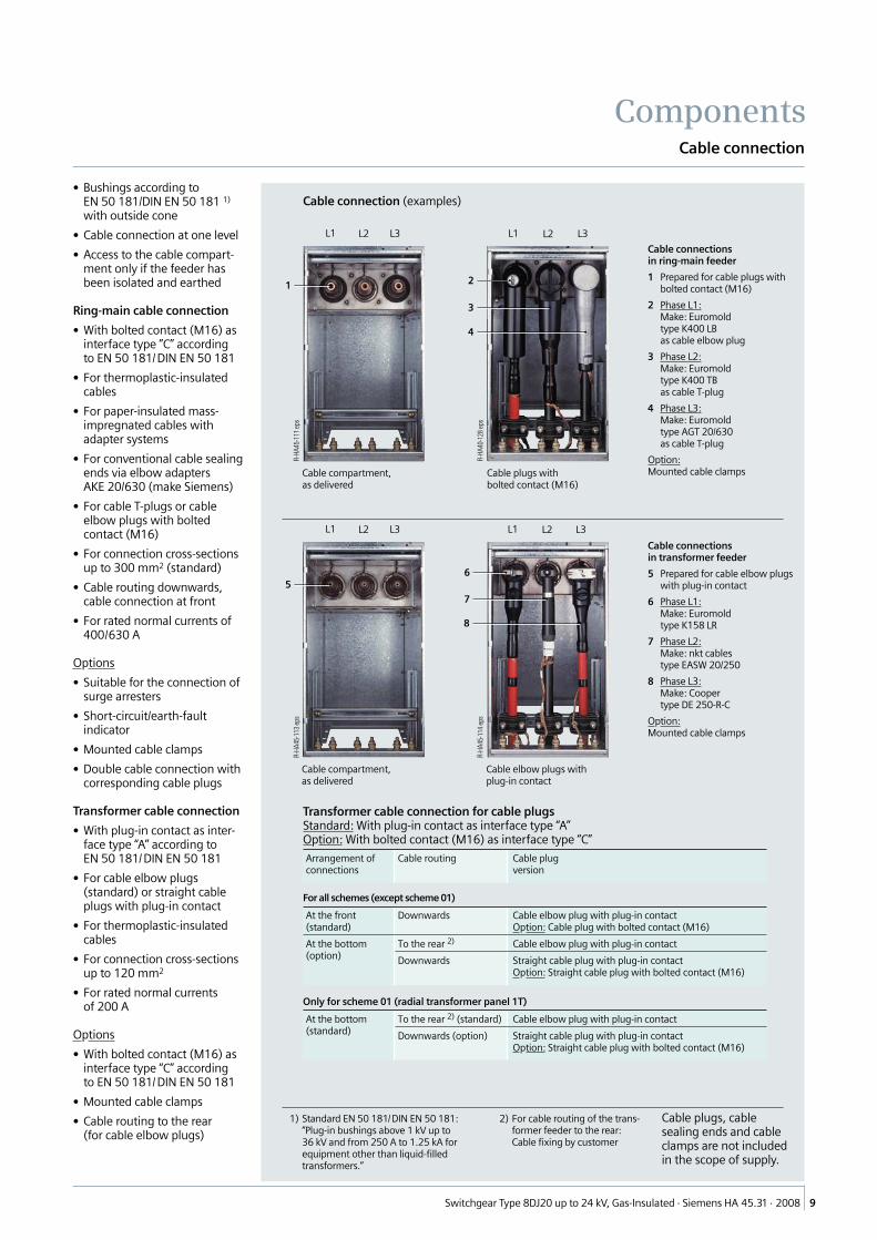
Cable connection (examples)
Cable connectionsin ring-main feeder
1 Prepared for cable plugs withbolted contact (M16)
2 Phase L1:Make: Euromoldtype K400 LBas cable elbow plug
3 Phase L2:Make: Euromoldtype K400 TBas cable T-plug
4 Phase L3:Make: Euromoldtype AGT 20/630as cable T-plug
Option:Mounted cable clampsCable plugs with
bolted contact (M16)Cable compartment,as delivered
R-HA
45-1
13ep
s
R-HA
40-1
28ep
s
R-HA
45-1
11ep
s
R-HA
45-1
14ep
s
Cable connectionsin transformer feeder
5 Prepared for cable elbow plugswith plug-in contact
6 Phase L1:Make: Euromoldtype K158 LR
7 Phase L2:Make: nkt cablestype EASW 20/250
8 Phase L3:Make: Coopertype DE 250-R-C
Option:Mounted cable clamps
Cable compartment,as delivered
Cable elbow plugs withplug-in contact
Transformer cable connection for cable plugsStandard: With plug-in contact as interface type “A”Option: With bolted contact (M16) as interface type “C”
Arrangement ofconnections
Cable routing Cable plugversion
For all schemes (except scheme 01)
At the front(standard)
Downwards Cable elbow plug with plug-in contactOption: Cable plug with bolted contact (M16)
At the bottom(option)
To the rear 2) Cable elbow plug with plug-in contact
Downwards Straight cable plug with plug-in contactOption: Straight cable plug with bolted contact (M16)
Only for scheme 01 (radial transformer panel 1T)
At the bottom(standard)
To the rear 2) (standard) Cable elbow plug with plug-in contact
Downwards (option) Straight cable plug with plug-in contactOption: Straight cable plug with bolted contact (M16)
1) Standard EN 50 181/DIN EN 50 181:“Plug-in bushings above 1 kV up to36 kV and from 250 A to 1.25 kA forequipment other than liquid-filledtransformers.”
1 2
3
4
L1 L2 L3 L3L2L1
56
7
8
L1 L2 L3 L3L2L1
Cable plugs, cablesealing ends and cableclamps are not includedin the scope of supply.
2) For cable routing of the trans-former feeder to the rear:Cable fixing by customer
Cable connection
Components

Switchgear Type 8DJ20 up to 24 kV, Gas-Insulated · Siemens HA 45.31 · 200810
����
����
�
���
���
��������������
���
���
���
����
����
��
��
����
����
���
�
���
� ��� �
��� ����
�
����
����
�
����
����
�
����
���
���
���
�
����
���
���
���
����
����
�
�
�
�
����
����
���
�
���
�
����
���
����
����
�
���
���
��������������
���
����
����
��
��
���
���
���
���
���
��������������
���
����
����
�
���
�
����
�
���
1 Bushing at the front for cable routing downwards (infeed)Standard: For cable elbow plugs with plug-in contactOption: For cable T-plugs with bolted contact (M16)
2 Bushing at the bottom as interface type “A” with plug-in contactfor cable routing to the rear (feeder T)
3 Bushing at the bottom as interface type “A” with plug-in contactfor cable routing downwards (feeder T)
4 Bolted joint of cable compartment cover (only for scheme 01)
Radial transformer panels · optionally in 3 overall heights
Scheme 01(with radial cableconnection as infeed)
1 Bushing at the front (standard) for cable routing downwards
2 Bushing at the bottom (option) for cable routing to the rear ordownwards
Section B-B Section B-B
Section B-BSection A-A
* Dimension depending on the bushing size and make/type of cable plug
** Dimensions depending on the overall heights of switchgear 1200 and 1400 mm
*** For cable routing to the rear, the depth dimensions are 10 mm deeper
BB Dimension for bushing as interface type “A” with plug-in contact
Transformerfeeder T
Radial cableconnection K(E)with make-proofearthing switch
Transformerfeeder T
Cable routingof feederdownwardswith straightcable plugs
Transformerfeeder T
Cable routingof feederto the rearwith cableelbow plugs
* Dimension depending on the bushing size and make/type of cable plug
** Dimensions depending on the overall heights of switchgear 1200 and 1400 mm
*** For cable routing to the rear, the depth dimensions are 10 mm deeper
B Dimension for bushing as interface type “C” with bolted contact (M16)
BB Dimension for bushing as interface type “A” with plug-in contact
(on
requ
est)
Dimension a
– 40 mm foroverall height 1400 mm
– 130 mm foroverall height 1200 mm
Dimension a
– 40 mm foroverall height 1400 mm
– 130 mm foroverall height 1200 mm
Scheme 21
Dimensions
Switchgear (for floor openings and fixing points refer to page 14)

Switchgear Type 8DJ20 up to 24 kV, Gas-Insulated · Siemens HA 45.31 · 2008 11
�
�
��
�
��
�
���
�
��
�
��
� �
�� ���
�
���
��
���
�
��
� � �
�� �� ��
���
�
�
��
�
�� ��
����
����
����
�
����
����
�
����
���
���
���
�
���
����
����
���
�
����
����
����
�
��
���
�� �� �� ��
��� ��� ��� ���
����
Block versions, consisting of ring-main feeders · optionally in 3 overall heights
Scheme 84
4 Bolted joint of cable compartment cover
Section A-A
** Dimensions depending on the overall heights of switchgear 1200 and 1400 mm
B Dimension for bushing as interface type “C” with bolted contact (M16)
Ring-mainfeeder RK
Dimension a
– 40 mm foroverall height 1400 mm
– 130 mm foroverall height 1200 mm
Scheme 02 (1RK withradial cable connection)
Further scheme types (side views, section A-A, see scheme 84)
Scheme 11 Scheme 32 Scheme 70
Switchgear (for floor openings and fixing points refer to page 14)
Dimensions

Switchgear Type 8DJ20 up to 24 kV, Gas-Insulated · Siemens HA 45.31 · 200812
����
����
����
�
��
� �
�
��� ��
�
�
��
� � �
�
��� �� ��
�
�
���
��
���
� � � �
�
��� �� �� ��
�
���
����
����
�
����
���
���
���
�
���
����
����
���
�
����
����
����
�
��
���
�� �� �� �
��� ��� ��� ����
�
����
����
����
�
���
���
��������������
���
���
���
����
����
��
��
����
���
Scheme 72
Section A-A
Ring-mainfeeder RK
Scheme 20
Further scheme types (for side views, sections A-A and B-B, see scheme 72)
Scheme 10 Scheme 71
Section B-B
Trans-formerfeederT
1 Bushing at the front (standard) for cable routing downwards
2 Bushing at the bottom (option) for cable routing to the rear ordownwards
* Dimension depending on the bushing size and make/type of cable plug
** Dimensions depending on the overall heights of switchgear 1200 and 1400 mm
*** For cable routing to the rear, the depth dimensions are 10 mm deeper
B Dimension for bushing as interface type “C” with bolted contact (M16)
BB Dimension for bushing as interface type “A” with plug-in contact
Dimension a
– 40 mm for overall height 1400 mm– 130 mm for overall height 1200 mm
Block versions, consisting of ring-main feeders and 1 transformer feeder · optionally in 3 overall heights
Dimensions
Switchgear (for floor openings and fixing points refer to page 15)

Switchgear Type 8DJ20 up to 24 kV, Gas-Insulated · Siemens HA 45.31 · 2008 13
����
����
����
�
�
���
��
���
�
��
� � �
�� �� ���
�
���
����
����
���
�
����
����
����
�
� �� �� �� �
�
����
��� ��� ��� ��� ���
�
����
����
�
����
���
���
���
�
���
����
����
�
���
���
��������������
���
���
���
����
����
��
��
����
���
Scheme 82
Section A-A
Ring-mainfeeder RK
Scheme 81
Section B-B
Trans-formerfeederT
Block versions, consisting of ring-main feeders and 2 transformer feeders · optionally in 3 overall heights
Dimension a
– 40 mm for overall height 1400 mm– 130 mm for overall height 1200 mm
1 Bushing at the front (standard) for cable routing downwards
2 Bushing at the bottom (option) for cable routing to the rear ordownwards
* Dimension depending on the bushing size and make/type of cable plug
** Dimensions depending on the overall heights of switchgear 1200 and 1400 mm
*** For cable routing to the rear, the depth dimensions are 10 mm deeper
B Dimension for bushing as interface type “C” with bolted contact (M16)
BB Dimension for bushing as interface type “A” with plug-in contact
Further scheme type (for side views, sections A-A and B-B, see scheme 82)
Switchgear (for floor openings and fixing points refer to page 15)
Dimensions

Switchgear Type 8DJ20 up to 24 kV, Gas-Insulated · Siemens HA 45.31 · 200814
�������
��
�
���
���
��
��
���
����
���
���
��
����
�
�
��
��
�����
����
����
���
��
����
���� �
�
�
��
�
��
�
����
����
����
�����
���
���
���
��
��
���
����
���
���
���
����
�
�
��
��
���
��
������
�
�
��
�
��������
��
����
��
�� �� ��
����
��
����
��
����
��
�� ���
���
���
����
�� �� �� �������
For transformer panels For block versions, consisting of ring-main feeders
Scheme 01
Scheme 84
����
����
����
�����
�
���
���
��
��
���
����
���
���
���
����
�
�
��
��
��
��
������
��������
��
����
��
�� ��
���
���
���
�
�
�
��
��
��
�
�
�
��
�������
Scheme 21
���
������
���
�� ��
� ����
�
Scheme 02 * and 11 *
��
����
����
����
�� ��
� ��
���
Scheme 32 *
���
��
����
����
���
�� ���
� ���
Scheme 70 *
Position of the floor openings for switchgear with pressure absorber system (for overall heights 1400 and 1760 mm)
�
����
����
����
���
�
� ��
���
���
��
��
��
Pressure absorbersystem forschemes02, 11, 20 and 21
�
���
� ��
� ����������
���
���
��
��
����
����
���� Pressure absorber
system forall otherschemes
1 Wall distance
13 Pressure relief duct
1 Wall distance
2 Fixing points
3 Position of the incoming cables for the incoming feeder
4 Position of the incoming cables for the outgoing feeder
5 Position of the incoming cables in the ring-main feeder
6 Position of the incoming cables in the cable feeder
7 Position of the incoming cables in the transformer feeder
8 Position of the incoming cables in the transformer feeder (option)
9 Floor opening for HV cables (and, if applicable, control cables)
10 Fixing frame (base) of the switchgear
11 Cutouts for an overall height of switchgear of 1200 mm
12 Cutouts for an overall height of switchgear of 1200 mm only whenconnecting the transformer cables to the bushing via straight cableplugs
1) Depending on additional options (e.g. surge arrester, 2nd cable, cable-typecurrent transformer) the corresponding floor openings have to be provided asstandard (see also page 16)
* Complete dimensions see top figure on the right
Furtherconnectioncombinations:
• For double cable connectionon request
• For surge arrester – Standardpossible for the following – 25 mm deepercable compartment covers: – 150 mm deeper
Dimensions
Floor openings (dimensions 1) in red) and fixing points

Switchgear Type 8DJ20 up to 24 kV, Gas-Insulated · Siemens HA 45.31 · 2008 15
����
����
����
���
���
��
�
��
��
�����
���������� �� ��
���
����
���
���
����
�
�
���
��� ��
���������� ���� ���� ����
�����
��
�� �� �� ��
�� ���
���
���
���
�
��
�
�
��
��
��
������� �� �����
����
����
����
���
���
���
���
����
���
���
���
����
�
��
��
���
��
������
�
�� �� ��
��
��
��
�
��
���
����
��������
��
����
��
����
��
����
��
���
���
���
�
�� ���
�
��
�
��
��
��
�
��
�� �� �� �������
For block versions, consisting of ring-main feedersand 1 transformer feeder
For block versions, consisting of ring-main feedersand 2 transformer feeders
Scheme 72 Scheme 82
�
�� ��
����
����
����
� ��
���
����
������
��� ��
�
�� ���
� ���
Position of the floor openings and fixing points for double cable connection in ring-main feeders����
���
����
����
���
�
�� ���
���
���
����
���
���
���
��
���
���
���
����
��
����
���� � ���
��
����
���
����
����
�����
Scheme 10 *(example)
Abbreviations
RK = Ring-main feederT = Transformer feeder
* Complete dimensions see top figure on the left
** Depending on the cable plug used (see also page 16)
*** 300 mm deeper cable compartment cover version
**** 105 mm deeper cable compartment cover version
Note:
Double cable connection in ring-main feedersonly possible for switchgear with an overallheight of 1400 mm
* Complete dimensions see top figures on the right and left
��
���
�� ���
����
����
����
� ���
��
�� ��
����
����
����
� ��
���
Scheme 20 *
Scheme 71 *
Scheme 10 * Scheme 81 *
1 Wall distance
2 Fixing points
5 Position of the incoming cables in the ring-main feeder
7 Position of the incoming cables in the transformer feeder
8 Position of the incoming cables in the transformer feeder (option)
9 Floor opening for HV cables (and, if applicable, control cables)
10 Fixing frame (base) of the switchgear
11 Cutouts for an overall height of switchgear of 1200 mm
12 Cutouts for an overall height of switchgear of 1200 mm only whenconnecting the transformer cables to the bushing via straight cableplugs1) Depending on additional options (e.g. surge arrester,
2nd cable, cable-type current transformer) other flooropenings have to be provided as standard accordingly(see also page 16)
Floor openings (dimensions 1) in red) and fixing points
Dimensions

Switchgear Type 8DJ20 up to 24 kV, Gas-Insulated · Siemens HA 45.31 · 200816
����
����
���
�
���
���
����
���
���
����������
������
�
���������
���
���
���
����
�
7 Elbow adapter,make Siemens,type AKE 20/630with conventional cablesealing end,make Lovink Enertech,type IAE 20
On request:8 Surge arrester,
make Siemens
����
����
���
�
���
���
����
���
���
�������
�
Standardcable compartment cover
9 Cable plug,make Südkabel,type SET (12/24)
10 Surge arrester,make Südkabel,type MUT (13/23)
11 Cable plug,make Südkabel,type SEHDT (13/23)
12 Surge arrester,make Südkabel,type MUW (12/22)
or
11 Cable plug,make Euromold,type (K)400 TB/G
12 Surge arrester,e.g. make Euromold,type 400 Pbor similar types ofconstruction
150 mm deeper cablecompartment cover
����
����
���
�
���
���
����
���
���
���������
����
����
����
���
���
���
��
���
������
��
��
Cable connection (examples for overall height 1400 mm)
3 Cable T-plug, make nkt cables,type CB 24-630 andCC 24-630
4 Cable T-plug, make Südkabel,type SET (12/24) and SET (12/24)with coupling insert KU 23.2
����
����
���
�
���
����
���
���
�������
�
���
���
���
���������
�
���
Cable compartment cover for double cable connection
1 Elbow adapter, make Siemens,type AKE 20/630 with conventionalcable sealing end, makeLovink Enertech, type IAE 20
2 Cable T-plug, make Euromold,type (K)400 TB/G
Standard cable compartment cover
25 mm deeper cablecompartment cover
����
����
��
���
��
����
��
�
�����
�
�
Standardcable compartment cover
Overall height of switchgear: 1400 mm
5 Cable plug,make Tyco Electronics,type RICS 5139
6 Surge arrester,make Tyco Electronics,up to type RDA21 andtype RDA24
Dimension a
– 610 mm up to type RDA21– 635 mm for type RDA24
Overall height of switchgear: 1200 mm
Numbers 5 and 6 not possible
Cable connection with surge arresters (examples for overall height 1400 mm)
Combination on request
Dimensions
Examples *** for cable connection in ring-main feeders
B Dimension for bushing with bolted contact (M16)
* Max. mounting space for cable and/or surge arrester
** Depth of floor opening
*** Non-binding examples; further examples see Catalog HA 40.1

Switchgear Type 8DJ20 up to 24 kV, Gas-Insulated · Siemens HA 45.31 · 2008 17
RK = Ring-main feederT = Transformer feederK(E) = Cable feeder for radial cable connection
with make-proof earthing switch
2) Depending onthe relevantequipment, e.g.motor operatingmechanism
Abbre-viations:
Transport overseas by seafreightPacking with PE protective foil and seaworthy crate
01 1T 1200 1.10 2.0 1.15 2.53 230
1400 1.10 2.0 1.15 2.53 250
1760 1.10 2.0 1.15 2.53 270
02 1RK 1200 1.10 2.0 1.15 2.53 270
1400 1.10 2.0 1.15 2.53 290
1760 1.10 2.0 1.15 2.53 320
10 2RK+1T 1200 1.45 2.0 1.15 3.34 450
1400 1.45 2.0 1.15 3.34 470
1760 1.45 2.0 1.15 3.34 510
11 2RK 1200 1.10 2.0 1.15 2.53 280
1400 1.10 2.0 1.15 2.53 290
1760 1.10 2.0 1.15 2.53 320
20 1RK+1T 1200 1.10 2.0 1.15 2.53 320
1400 1.10 2.0 1.15 2.53 340
1760 1.10 2.0 1.15 2.53 370
21 1K(E)+1T 1200 1.10 2.0 1.15 2.53 310
1400 1.10 2.0 1.15 2.53 340
1760 1.10 2.0 1.15 2.53 370
32 3RK 1200 1.45 2.0 1.15 3.34 380
1400 1.45 2.0 1.15 3.34 400
1760 1.45 2.0 1.15 3.34 440
70 4RK 1200 1.80 2.0 1.15 4.14 470
1400 1.80 2.0 1.15 4.14 500
1760 1.80 2.0 1.15 4.14 550
71 3RK+1T 1200 1.80 2.0 1.15 4.14 530
1400 1.80 2.0 1.15 4.14 560
1760 1.80 2.0 1.15 4.14 610
72 4RK+1T 1200 2.05 2.0 1.15 4.72 640
1400 2.05 2.0 1.15 4.72 670
1760 2.05 2.0 1.15 4.72 730
81 2RK+2T 1200 1.80 2.0 1.15 4.14 590
1400 1.80 2.0 1.15 4.14 620
1760 1.80 2.0 1.15 4.14 670
82 3RK+2T 1200 2.05 2.0 1.15 4.72 700
1400 2.05 2.0 1.15 4.72 730
1760 2.05 2.0 1.15 4.72 790
84 5RK 1200 2.05 2.0 1.15 4.72 580
1400 2.05 2.0 1.15 4.72 610
1760 2.05 2.0 1.15 4.72 670
Transport in Europe by rail, truck, containerPacking with PE protective foil and wooden base
01 1T 1200 1.10 1.4 1.10 1.69 170
1400 1.10 1.6 1.10 1.94 180
1760 1.10 1.96 1.10 2.37 210
02 1RK 1200 1.10 1.4 1.10 1.69 210
1400 1.10 1.6 1.10 1.94 230
1760 1.10 1.96 1.10 2.37 260
10 2RK+1T 1200 1.45 1.4 1.10 2.23 370
1400 1.45 1.6 1.10 2.55 400
1760 1.45 1.96 1.10 3.13 440
11 2RK 1200 1.10 1.4 1.10 1.69 210
1400 1.10 1.6 1.10 1.94 230
1760 1.45 1.96 1.10 3.13 260
20 1RK+1T 1200 1.10 1.4 1.10 1.69 260
1400 1.10 1.6 1.10 1.94 280
1760 1.10 1.96 1.10 2.37 310
21 1K(E)+1T 1200 1.10 1.4 1.10 1.69 260
1400 1.10 1.6 1.10 1.94 280
1760 1.10 1.96 1.10 2.37 310
32 3RK 1200 1.45 1.4 1.10 2.23 300
1400 1.45 1.6 1.10 2.55 330
1760 1.45 1.96 1.10 3.13 370
70 4RK 1200 1.80 1.4 1.10 2.77 380
1400 1.80 1.6 1.10 3.17 420
1760 1.80 1.96 1.10 3.88 470
71 3RK+1T 1200 1.80 1.4 1.10 2.77 440
1400 1.80 1.6 1.10 3.17 480
1760 1.80 1.96 1.10 3.88 530
72 4RK+1T 1200 2.05 1.4 1.10 3.16 510
1400 2.05 1.6 1.10 3.61 560
1760 2.05 1.96 1.10 4.42 620
81 2RK+2T 1200 1.80 1.4 1.10 2.77 500
1400 1.80 1.6 1.10 3.17 540
1760 1.80 1.96 1.10 3.88 590
82 3RK+2T 1200 2.05 1.4 1.10 3.16 570
1400 2.05 1.6 1.10 3.61 620
1760 2.05 1.96 1.10 4.42 680
84 5RK 1200 2.05 1.4 1.10 3.16 450
1400 2.05 1.6 1.10 3.61 500
1760 2.05 1.96 1.10 4.42 560
Sche-meno.
Version(abbre-viations)
Switch-gearheight(with-out 1)LVcompart-ment)mm
Transportdimensions 1)
Width Height Depth
m m m
Vol-ume
m3
Gross 2)
weight
approx.kg
Sche-meno.
Version(abbre-viations)
Switch-gearheight(with-out 1)LVcompart-ment)mm
Transportdimensions 1)
Width Height Depth
m m m
Vol-ume
m3
Gross 2)
weight
approx.kg
8DJ20 switchgear isdelivered as completetransport unit.
The following must benoted:
• Transport facilities onsite
• Transport dimensionsand weights
• Size of door open-ings in building
• Switchgear with LVcompartment:Please take othertransport dimensionsand weights intoaccount
Packing
Place of destination in-side Germany or otherEuropean countries
• Means of transport:Rail and truck
• Type of packing:– Panels on open
pallets– Covered with PE
protective foil
Place of destinationoverseas
• Means of transport:Ship
• Type of packing:– Panels on open
pallets– In closed crates with
sealed PE protectivefoil
– With desiccant bags– With sealed wooden
base– Max. storage time:
6 months
1) With LV compartment:Other transportdimensions andweights
Transport data
Shipping
Types of transport

Switchgear Type 8DJ20 up to 24 kV, Gas-Insulated · Siemens HA 45.31 · 200818
Option low-voltagecompartment
• Overall height– Standard: 400 mm– Option: 600 or 900 mm– Option: Cover
• Installation on the switchgear– Possible per feeder– Customer-specific
configuration– Separate cable duct on the
switchgear next to thelow-voltage compartment
Shipping and transport data
If the switchgear is deliveredwith low-voltage compartment,other transport dimensions andweights have to be taken intoaccount.
Switchgear installation
Free-standing arrangement(on request)
(Switchgear installation only forpressure relief downwards)
�� ���
����
����
����
����
����
����
���
�� ���
����
����
����
����
����
����
���
�� ���
����
����
����
����
���
Switchgear height
1200 mm 1400 mm 1760 mm
Combinations with low-voltage compartmentDimensions e.g. for scheme 20
Wall-standing arrangement
Overall height 1200 mm
Direction ofpressure relief
Overall height 1400 mm
Downwards
DownwardsOption: to the rear
Overall height 1760 mm
DownwardsOption: to the rear
Pressure relief downwards(all overall heights)
Option: Pressure relief tothe rear, overall height ofswitchgear 1400 or 1760 mm(only for transformer cableconnection downwards)
1 Switchgear
2 Floor opening into cable duct
3 Expanded metal(not included in the scopeof supply)
4 Direction of pressure relief
5 Cable
6 Partition (e.g. of sheet-metal, not included in thescope of supply)
7 Wall distance
8 Rear cutout in theswitchgear (size approx.350 mm x 615 mm, notfor scheme 01/ = 1T)
���
���
����
����
���
�
�
�
�
�
�
�
� ����
����
���
�
�����
��� �
�
�
�
�
�
�
Designs
Switchgear with low-voltage compartment, switchgear installation

Switchgear Type 8DJ20 up to 24 kV, Gas-Insulated · Siemens HA 45.31 · 2008 19
Application
8DJ20 switchgear in outdoorenclosures is used where thenetwork structure requires this,but without transformers andlow-voltage distributionboards.
Features
• Two sizes– For switchgear with 3 feeders– For switchgear with 4 feeders
• Degree of protection IP 44
• 8DJ20 switchgear installed inoutdoor enclosure
• Cable compartment parti-tioned off adjacent feeders
• With lockable door
• Complete interlockingfunctions
Cable connection
See pages 9 and 16.
• Cable entry from below
• Floor cover– Divided and bolted– Removable for inserting the
cables
• Cable bracket movableupwards or to the rear to suitcable sealing ends
• Cables fixed by cable clamps(option) on C-rails of cablebracket
• Option:Cable clamps
Schemes
• For 3-panel outdoorenclosure:
– Scheme 10– Scheme 32
• For 4-panel outdoorenclosure:
– Scheme 70– Scheme 71– Scheme 81
** Option: Surge arrester
Only such surge arresters canbe used which are suitable for acable compartment cover flushwith the operating front,e.g. make Tyco Electronics,type RDA (see also Catalog HA 40.1“Cable connections”).
For 3-panel switchgear
Outdoor enclosurewith 2-wing door
Overall width 1150 mm
Outdoor enclosurewith 2-wing door
Overall width 1500 mm
As above,however withdoors removed, some cablecompartment covers removed
As above,however with doors removed
For 4-panel switchgear
R-HA
45-1
15ce
ps
R-HA
45-1
17ce
psR-
HA45
-118
dep
s
R-HA
45-1
16d
eps
Scheme10 **
Scheme32 **
Scheme70 **
Scheme71 **
Scheme81 **
����
����
���
�
�� ���
����
����
���
�
�� ����
����
����
���
�
�� ���� ��
����
����
���
�
�� ��� ��
����
����
���
�
�� ����
Outdoor enclosures with 8DJ20 switchgear
Special Designs

Switchgear Type 8DJ20 up to 24 kV, Gas-Insulated · Siemens HA 45.31 · 200820
����
����
����
���
�
�
���
��������
���
����
����
���
���
����
����
���������
�
�
�
�
�
�
��
��� ��
Sectional view of ring-main feeder
���
��������
���
����
����
���
����
����
����
����
���
�
�
����
���������
��� ��
�
�
�
��
�
Dimensions
Outdoor enclosurewith 2-wing doorfor 3-panel switchgear
Outdoor enclosurewith 2-wing doorfor 4-panel switchgear
Sectional view of transformer feeder
1 Door of outdoor enclosure
2 Floor fixing 4 x ;14 mm
3 HV HRC fuse assembly
4 Operating mechanism
5 Switchgear vessel
6 Bushing for cable connection
7 Cable elbow plug with plug-in contact
8 Cable T-plug with bolted contact (M16)
9 Pressure relief device
10 Wall distance W 200 mm
* Floor fixing dimension
For position of incoming cablessee pages 14 and 15
For cable connections withsurge arresters see page 16
Special Designs
Outdoor enclosures with 8DJ20 switchgear

Switchgear Type 8DJ20 up to 24 kV, Gas-Insulated · Siemens HA 45.31 · 2008 21
Overview of standards (March 2008)
IEC standard VDE standard EN standard
Switchgear 8DJ20 IEC 62 271-1 VDE 0671-1 EN 62 271-1
IEC 62 271-200 VDE 0671-200 EN 62 271-200
Switching devices Circuit-breaker IEC 62 271-100 VDE 0671-100 EN 62 271-100
Disconnector andearthing switch
IEC 62 271-102 VDE 0671-102 EN 62 271-102
Switch-disconnector IEC 60 265-1 VDE 0670-301 EN 60 265-1
Switch-disconnector /fuse combination
IEC 62 271-105 VDE 0671-105 EN 62 271-105
HV HRC fuses IEC 60 282-1 VDE 0670-4 EN 60 282
Voltage detecting systems IEC 61 243-5 VDE 0682-415 EN 61 243-5
Degree of protection – IEC 60 529 VDE 0470-1 EN 60 529
Insulation – IEC 60 071 VDE 0111 EN 60 071
Instrument transformers Current transformers IEC 60 044-1 VDE 0414-1 EN 60 044-1
Voltage transformers IEC 60 044-2 VDE 0414-2 EN 60 044-2
Combined transformers 1) IEC 60 044-3 VDE 0414-5 EN 60 044-3
Installation – IEC 61 936-1 VDE 0101 –
Standards
The 8DJ20 switchgearcomplies with the relevantstandards and specificationsapplicable at the time oftype tests.
In accordance with theharmonization agreementreached by the countries of theEuropean Community, theirnational specificationsconform to the IEC standard.
Dielectric strength
See also Catalog HA 40.1“Standards”.
Terms
“Make-proof earthing switches”are earthing switches withshort-circuit making capacityaccording to IEC 62 271-102/VDE 0671-102.
Climate and environmentalinfluences
8DJ20 switchgear is completelyenclosed and insensitive toclimatic influences.
• Climatic tests fulfilled inaccordance with IEC 60 932(report)
• All medium-voltage devices(except for HV HRC fuses)are installed in a gas-tight,welded stainless-steelswitchgear vessel which isfilled with SF6 gas
• Live parts outside the switch-gear vessel are provided withsingle-pole enclosure
• At no point can creepagecurrents flow from high-voltage potentials to earth
• Operating mechanism partswhich are functionally impor-tant are made of corrosion-proof materials
• Bearings in operating mech-anisms are designed as dry-type bearings and do notrequire lubrication
• Suitable instrument trans-former designs
Type of service location
8DJ20 switchgear can beused as indoor installations inaccordance with IEC 61 936(Power installations exceeding1 kV AC) and VDE 0101:
• Outside lockable electricalservice locations at placeswhich are not accessible tothe public. Enclosures ofswitchgear can only beremoved with tools.
• Inside lockable electricalservice locations. A lockableelectrical service location is aplace outdoors or indoors thatis reserved exclusively forhousing electrical equipmentand which is kept under lockand key. Access is restrictedto authorized personnel andpersons who have been prop-erly instructed in electricalengineering. Untrained orunskilled persons may onlyenter under the supervision ofauthorized personnel or prop-erly instructed persons.
Internal arc classification(option)
The possibility of arc faults ingas-insulated switchgear type8DJ20 is improbable and amere fraction of that typical ofearlier switchgear types, dueto:
• Use of gas-filled switchgearcompartments
• Use of suitable switchingdevices such as three-position switches with make-proof earthing switch
• Logical mechanical interlocks
• Use of ring-core current trans-formers (option)
Optionally, switchgear type8DJ20 can be designed withinternal arc classification:
• Internal arc classification IAC
• Type of accessibility A(for authorized personnelonly)
• Accessible sides– Side F (front)– Side L (lateral)– On request: Side R (rear)
• Arc test currentup to 21 kA /1 s
1) Only for switchgear type 8DH10
Standards, specifications, guidelines
Standards

Switchgear Type 8DJ20 up to 24 kV, Gas-Insulated · Siemens HA 45.31 · 200822
Classification of 8DJ20 switchgear according to IEC 62 271-200
Design and construction
Partition class PM (metallic partition)
Loss of service continuity category 1)
Switchgear– With HV HRC fuses– Without HV HRC fuses (RK, T, LST)
LSC 2ALSC 2B
Accessibility to compartments(enclosure)
– Busbar compartment– Switching-device compartment– Low-voltage compartment (option)– Cable compartment
– Switchgear with HV HRC fuses (T…)– Switchgear without HV HRC fuses– Switchgear scheme 01 (1 T)
Access option
– Non-accessible– Non-accessible– Tool-based
– Interlock-controlled– Interlock-controlled– Tool-based
Internal arc classification (option)
Designation ofinternal arc classification IACIAC for
– Wall-standing arrangement (standard)
Rated voltage 7.2 kV to 24 kV
IAC A FL 21 kA, 1 s
Type of accessibility A
– F– L
Switchgear in closed electrical service location,access “for authorized personnel only” (acc. to IEC 62 271-200)FrontLateral
Arc test current 2) Up to 21 kA
Test duration 1 s
1) The loss of service continuity categoryis always referred to the completeswitchgear, i.e. the panel with thelowest category defines the loss ofservice continuity category of thecomplete switchgear.
2) 8DJ20 switchgear with pressureabsorber:Arc test current up to 16 kA,for overall height of switchgear1400 and 1760 mm.
Standards
Classification

Switchgear Type 8DJ20 up to 24 kV, Gas-Insulated · Siemens HA 45.31 · 2008 23
If not stated otherwise onthe individual pages of thiscatalog, we reserve the rightto include modifications, espe-cially regarding the stated val-ues, dimensions and weights.
Drawings are not binding.
All product designations usedare trademarks or productnames of Siemens AG or othersuppliers.
If not stated otherwise, alldimensions in this catalog aregiven in mm.
Responsible for
Technical contents:Christoph MaulSiemens AG, Dept. PTD M 2 PPMErlangen
General editing:Gabriele PollokSiemens AG, Dept. PTD CC MErlangen
Notes

For questions concerningPower Transmission and Distribution:You can contact our Customer SupportCenter 24 hours a day, 365 days a year.Tel.: +49 180/524 70 00Fax: +49 180/524 24 71(Charges depending on provider)E-Mail: [email protected]/energy-support
Subject to change without noticeOrder No.: E50001-K1445-A311-A7-7600Printed in GermanyDispo 31606KG 04.08 6.0 24 En103135 6101/6528
The information in this document contains general descriptions of the technical options available, which do not always have to be present in individual cases.The required features should therefore be specified in each individual case at the time of closing the contract.
Siemens AGEnergy SectorMedium Voltage DivisionPostfach 32 4091050 ErlangenGermany
www.siemens.com/medium-voltage-switchgear