switching logic for converting off-grid pv customers to on ... · in mode 2, for voltage sag from...
TRANSCRIPT

ORIGINAL CONTRIBUTION
Switching Logic for Converting Off-grid PV Customers to On-grid by Utilizing Off-grid Inverter and Battery
A. R. Anishkumar1 • P. Sreejaya1
Received: 13 March 2015 / Accepted: 4 January 2016 / Published online: 25 May 2016
� The Institution of Engineers (India) 2016
Abstract Kerala is a state in India having a very good
potential for solar PV energy production. The domestic
customers in Kerala using PV system are approximately
15 % and almost all of them are using the off-grid PV
system. When these off grid customers move to on-grid
system, off grid system accessories such as inverter and
batteries become redundant. In this paper, a switching logic
has been developed for the effective utilization of off grid
accessories and reducing islanding power loss for on grid
customers. An algorithm is proposed for the switching
logic and it is verified using simulation results and hard-
ware implementation.
Keywords Off grid solar PV system �Grid connected PV system � Micro inverter �ON grid inverter � Switching logic for islanding problem
Introduction
Photovoltaic generation system can be divided into the off-
grid solar inverter system and the grid-tied solar inverter
system. The off-grid solar inverter system is mainly used in
composition-independent photovoltaic power generation
system, applied in the family, the countryside, island, and
remote areas of the power supply, and urban lighting,
communications, testing and application of the system of
power supply. Figure 1 is a system block diagram that
shows the main components of the off grid solar inverter
system, which consists of a solar panel, maximum power
point tracking (MPPT) charge controller, battery, dc-ac
inverter and ac load.
While the grid-tie solar inverter system is mainly used
in parallel with the traditional utility grid, the solar
inverter converts the energy from the PV panel to the
traditional utility grid. The main components are solar
panels and microinveters (Fig. 2). Microinverter converts
direct current generated by a single solar module to AC.
Output from several microinvertes are combined and fed
to the electric grid. Microinverters have several advan-
tages over conventional inverters. The main advantage is
that small amounts of shading, on any one solar module,
do not disproportionately reduce the output of the entire
array. Each microinverter harvests optimum power by
performing maximum power point tracking for its con-
nected module.
Grid-tie inverters are also designed to quickly discon-
nect from the grid if the utility grid goes down. This is an
national electrical code (NEC) requirement that ensures
that in the event of a blackout, the grid tie inverter will shut
down to prevent the energy it transfers from harming any
line workers who are sent to fix the power grid. This is
called an islanding condition.
Methodology
This paper focuses on the off grid users in Kerala. When
off grid users move to on grid system, off grid system
accessories such as inverter, MPPT charge controller and
batteries become redundant. Another issue related with on
grid system is the power loss at the time of islanding; the
load does not get any power from the panel or from the
grid.
& P. Sreejaya
1 Department of Electrical Engineering, College of
Engineering, Trivandrum, India
123
J. Inst. Eng. India Ser. B (December 2016) 97(4):581–588
DOI 10.1007/s40031-016-0240-x

For the effective utilization of off grid accessories and
reducing islanding power loss, a switching logic has been
developed. This switching logic is incorporated in a
MATLAB model of off grid system which can be con-
nected to an on grid model with micro inverter. The
working of the logic is verified using simulation results and
hardware implementation.
Switching Logic
Switching logic improves the efficiency of both on grid and
off grid system. In on grid system, at the time of grid fault,
PV panel power is wasted because of islanding. The
problem can be solved by incorporating an off grid system
with an on grid system. By using the switching logic, the
system can be operated in two modes. Mode 1 represents
the normal working condition and mode 2 represents grid
fault condition or islanding.
Mode 1
From Fig. 3, at normal working condition, switches S1 and
S2 are closed and micro inverter is tied to the grid and S6 is
closed to charge the battery. Battery charging is limited to
60 % and the balance charging is done under islanding
condition. Load is supplied by closing S3. All the other
switches are in open condition.
Mode 2
At the time of grid fault S1, S3, S5 and S6 are opened and
S2 and S4 are closed so that on grid system is changed to
off grid system. The balance charging is done in this
mode.
Algorithm
Algorithm is shown in flowchart (Fig. 4)
1. Start
2. Initial settings are done that is, the load reference
(Idref) is set to I1 and panel reference current (Ipref) is
Fig. 1 Off grid solar inverter
system
Fig. 2 Grid tie solar inverter system
Fig. 3 Switching logic block
diagram
582 J. Inst. Eng. India Ser. B (December 2016) 97(4):581–588
123

set to I2, grid voltage reference (Vgrid) is set to V1.
All switches in off condition.
3. Panel current is measured.
4. Check whether the measured panel current (Ip) is
greater than or less than the reference panel current.
If panel current is greater than reference panel
current, then switch on S1, S2. If panel current less
than reference panel current (PV output is less), then
measure the battery charge (Bc). Then check whether
battery charge is greater than Bdm (Battery charge
minimum) or not. If yes, then turn on S4, so that load
is supplied from the battery and repeat the loop,
otherwise go to step 8.
5. Measure the grid voltage (Vg). Calculate the differ-
ence between grid voltage and reference grid voltage
(Vd).
6. Check whether the difference is less than or greater
than the threshold value Vdm (voltage difference
minimum). If the Vd is less than the threshold value
then the grid is healthy and so turn on S5, S3 and turn
off S2. Now the system is ONGRID. The load is
supplied by the grid and also by the panel.
Fig. 4 Flowchart
J. Inst. Eng. India Ser. B (December 2016) 97(4):581–588 583
123

7. If Vd is greater than the threshold value then the grid
is not healthy and so turn on S4 and turn off S1 and
the system is OFFGRID. Load is supplied by the
panel. Go to step no 9.
8. Check the battery charge (Bc). If the battery charge is
greater than BCM (battery charge maximum), the loop
is repeated, if not, turn on S6 to charge the battery up
to BCM.
9. Measure the load current (IL), compare the load
current with the reference value. If the measured
current is less than the reference current, turn off S1,
S5, S3, S6, and S4. That is no load in the system. If
the measured current is greater than the reference
current then repeat the loop. Reference current is zero
(no load).
10. Stop.
Simulation
PV panel, MPPT charge controller, boost converter, off
grid inverter and on grid inverter are modeled in
MATLAB [1, 2]. The perturb and observe (P&O) method
is used for MPPT [3, 4]. Figure 3 is simulated and
depending on the grid condition, system can be made to
work both on grid and off grid with the help of six
switches [5]. Let us consider two modes of operation;
mode 1 is normal condition, where the system is working
as an on grid system. In this mode, load is powered by
both grid and PV panel.
In mode 2, for voltage sag from 0.2 s to 0.4 s, the sys-
tem is switched to off grid system and the load is served
from the solar panel.
Simulation Results
Simulation parameters are given in Table 1. Figure 5
shows the output voltage waveform of 95 V PV panel.
The panel is connected to the on grid system and off
grid system by switches S1 and S2 respectively. In
normal working condition (mode 1), S1 is closed and S2
is opened. So the panel is connected to the on grid
inverter. In mode 2, S1 is opened and S2 is closed so
that the panel is connected to off grid inverter. The
algorithm is explained earlier and is applied. The fol-
lowing results are obtained.
Figure 6 shows the grid voltage and load voltage when
there is a voltage sag in the grid from0.02 s to 0.04 s. The load
voltage remains constant because of the switching action.
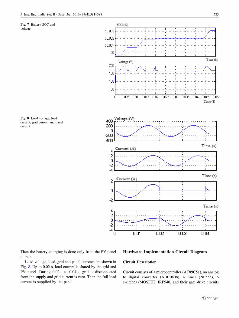
Since switch S6 is closed in normal condition up to
0.02 s, battery is charged from both grid voltage and PV
panel voltage as shown in Fig. 7.
From 0.02 s to 0.04 s, there is a voltage sag in the grid
when S2 and S4 are closed and all other switches are open.
Table 1 Simulation parameters
PV Output Voltage 200 W 95 V 2 A
Battery 150 V
Voltage Sag 0.02–0.04
Load RL load R = 100 X; L = 0.01 lH
Fig. 5 PV panel output voltage
Fig. 6 Grid voltage and load
voltage
584 J. Inst. Eng. India Ser. B (December 2016) 97(4):581–588
123
Then the battery charging is done only from the PV panel
output.
Load voltage, load, grid and panel currents are shown in
Fig. 8. Up to 0.02 s, load current is shared by the grid and
PV panel. During 0.02 s to 0.04 s, grid is disconnected
from the supply and grid current is zero. Then the full load
current is supplied by the panel.
Hardware Implementation Circuit Diagram
Circuit Description
Circuit consists of a microcontroller (AT89C51), an analog
to digital converter (ADC0808), a timer (NE555), 6
switches (MOSFET, IRF540) and their gate drive circuits
Fig. 7 Battery SOC and
voltage
Fig. 8 Load voltage, load
current, grid current and panel
current
J. Inst. Eng. India Ser. B (December 2016) 97(4):581–588 585
123

(IR2110), a voltage regulator (IN7805) and an op-amp
(LM324) as shown in Fig. 9.
The controller controls all the switches after getting
appropriate commands. Since the controller reads only
digital data, the analog values of voltage and currents from
different equipments are converted to digital values by
ADC. Both ADC and controller get the supply from the
battery in the system by voltage regulator. The clock signal
for ADC is obtained from 555 timer.
The grid voltage, inverter voltage, battery voltage,
voltage corresponding to panel current and voltage cor-
responding to load current are given to different channels
of ADC (CH0,CH1,CH2,CH3,CH4 respectively). These
analog values are converted to digital values and given to
the controller. Controller checks the conditions and gives
appropriate commands to the driver circuits of MOSFET.
6 pins of controller (P1.0, P1.1, P1.2, P1.3, P1.4, and
P1.5) are used for sending the switching signals to driver
IC.
Fig. 9 Circuit diagram
Fig. 10 Experimental setup
Fig. 11 Grid share in normal condition
586 J. Inst. Eng. India Ser. B (December 2016) 97(4):581–588
123

Hardware Set Up and Results
The experimental setup includes 250 W, 30 V PV panel,
250 W micro inverter, 24 V, 1kVA off-grid inverter,
1 kW MPPT charge controller, 24 V 100 Ah lead acid
tubular battery, a charging circuit and 60 W lamp load as
shown in Fig. 10. The system works as per the algorithm
explained. Bdm is taken as 10 % and BCM is taken as
60 %. In normal condition, PV panel is connected to grid
through micro inverter and the load is supplied by both
grid and micro inverter. At the same time, the battery is
charged through the converter. If the battery is charged to
60 % then it is disconnected from the grid. If grid is
disconnected from the system, the load is supplied by
panel through off-grid inverter. If both the grid and panel
are out of service, load is supplied by battery through off-
grid inverter.
Case 1: Grid and PV Sharing the Load
Figure 11 shows the voltage, current and power supplied to
load from grid during normal condition. The grid share is
16.09 W and the rest of the load power is shared by the
micro inverter.
Case2: Power Flowing Towards the Grid
When the load is switched off, the solar power of 42.77 W
flows towards the grid (opposite sign) and it is shown in
Fig. 12.
Case3: Islanding (Grid under Fault)
Since the micro inverter disconnected PV from grid, load is
supplied from Off grid inverter and the output is shown in
Fig. 13. dc output of PV panel under this condition is
shown in Fig. 14.
Conclusion
This paper proposes the model of an on grid micro inverter
connected to an off grid system. By using a switching
logic, the load can be served by both the grid and the PV
panel. Under islanded condition, it is served from the
panel. Both the simulation and experimental results verifies
the working of the switching logic.
Thus an existing off grid customer can use his off grid
inverter and batteries when he goes for an on grid con-
nection while rectifying the major issue of islanding
problem.
Acknowledgments The authors would like to thank College of
Engineering, Trivandrum, Kerala, India for funding the project.
References
1. M.E. Ropp, S. Gonzalez, Development of a MATLAB/Simulink
model of a single-phase grid-connected photovoltaic system.
IEEE. Trans. Energy Conver. 24(1), 195–202 (2009)
Fig. 12 Solar power to grid under no load condition
Fig. 13 Off grid inverter output in islanding condition
Fig. 14 PV panel dc output in islanding condition
J. Inst. Eng. India Ser. B (December 2016) 97(4):581–588 587
123

2. S. Ozturk, I. Cadirci, DSPIC microcontroller based implementa-
tion of a flyback PV microinverter using direct digital synthesis,
Energy Conver Congress Expos. (ECCE), 15–19 Sept 2013
3. D.S. Selvan, Modeling and simulation of incremental conductance
MPPT algorithm for photovoltaic applications. Int. J. Sci. Eng.
Technol. 2(7), 681–685 (2013)
4. H.N. Zainudin, S. Mekhilef, Comparison study of maximum power
point tracker techniques for PV systems, Proceedings of the 14th
International Middle East Power Systems Conference (MEP-
CON’10), Egypt, December 19–21, 2010
5. A.R. Anishkumar, P. Sreejaya, Micro inverter based flexible
storage for PV grid tied system, National Conference on Techno-
logical Trends (NCTT) 2014, Trivandrum, August 22–23, 2014
588 J. Inst. Eng. India Ser. B (December 2016) 97(4):581–588
123