swixinstruc cs a - carid.com 11121314151617181920
TRANSCRIPT
SWI-X Universal Steering Wheel Control Interface
Installation Instructions
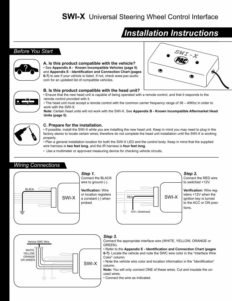
Before You Start
A. Is this product compatible with the vehicle?• See Appendix A - Known Incompatible Vehicles (page 5) and Appendix E - Identification and Connection Chart (pages 6-7) to see if your vehicle is listed. If not, check www.pac-audio.com for an updated list of compatible vehicles.
B. Is this product compatible with the head unit?• Ensure that the new head unit is capable of being operated with a remote control, and that it responds to the remote control provided with it.• The head unit must accept a remote control with the common carrier frequency range of 38 – 40Khz in order to work with the SWI-X.Note: Certain head units will not work with the SWI-X. See Appendix B - Known Incompatible Aftermarket Head Units (page 5).
C. Prepare for the installation.• If possible, install the SWI-X while you are installing the new head unit. Keep in mind you may need to plug in the factory stereo to locate certain wires; therefore do not complete the head unit installation until the SWI-X is working properly.• Plan a general installation location for both the SWI-X LED and the control body. Keep in mind that the supplied wire harness is two feet long, and the IR harness is four feet long. • Use a multimeter or approved measuring device for checking vehicle circuits.
Wiring ConnectionsStep 1.Connect the BLACK wire to ground (-).
Verification: Wire or location registers a constant (-) when probed.
Step 2.Connect the RED wire to switched +12V.
Verification: Wire reg-isters +12V when the ignition key is turned to the ACC or ON posi-tions.
Step 3.Connect the appropriate interface wire (WHITE, YELLOW, ORANGE or GREEN).• Refer to the Appendix E - Identification and Connection Chart (pages 6-7). Locate the vehicle and note the SWC wire color in the “Interface Wire Color” column. • Note the vehicle wire color and location information in the “Identification” column.Note: You will only connect ONE of these wires. Cut and insulate the un-used wires. • Connect the wire as indicated.
SWI-X

�����
SWI-X
Wiring Connections (cont.)Step 4If necessary, perform the following operations as indicated by the notes in Appendix E - Identification and Connection Chart (pages 6-7). If no connections are necessary, proceed to Step 5.
Step 4a.If necessary, connect the BLUE serial data wire.Connect this wire ONLY on GM pas-senger vehicles (no trucks or SUVs) with airbags AND steering wheel heater controls. For all other vehicles, cut and insulate the BLUE wire.
Step 4b.If necessary, cut the BROWN wire loop and insulate both halves.
Step 4c.If necessary, either cut the VIOLET wire loop and insulate both halves, or place a re-sistor in-line if directed.
Programming the SWI-X to Work With the VehicleIMPORTANT! Some steps of the programming instructions must be completed within a certain number of seconds following the previous step. Review the complete instruction before beginning the programming sequence.
Step 5.Refer to Appendix C - Head Units That Require IR Extended Mode On (page 5) and Appendix E - Identification and Connection Chart (pages 6-7). Note the IR Extended Mode Setting and Version Number next to the selected vehicle. Fill in the information below for quick reference.
IR Extended Mode Setting: ____________ Version Number: ____________
Step 6.Press and hold programming/mode button on SWI-X. Turn the vehicle ignition to the ON position.
Both LEDs on SWI-X will light.
Step 7.Release the programming/mode button.
Both LEDs will turn off, indicating memory is cleared, then turn on again for only 3 seconds.
Step 8.To turn IR Extended Mode ON:Press and release the program- ming button within 3 seconds.To leave IR Extended Mode OFF: Do nothing for 3 seconds.
Note: To change IR Extended Mode later, restart procedure at Step 6. Steps 11-24 (learning radio commands) must also be repeated.
Both LEDs will turn off.
Step 9.Press and release the programming/mode button the same number of times as the desired version number.
LEDs will flash each time the button is pressed.
After 3 seconds, LEDs will flash to indicate set version number. Left LED: 10’s placeRight LED: 1’s place
Step 10.Turn vehicle ignition to OFF position. Programming sequence is complete.
SWI-X
OFF
ACC
IGN
STRT
SWI-X
SWI-X SWI-X
SWI-XOFF
ACC
IGN
STRT
�����
�����

VOL
SWI-X
SWI-X
SWI-XSWI-X
Programming the SWI-X to Control the Head UnitIMPORTANT! Some steps of the programming instructions must be completed within a certain number of seconds following the previous step. Review the complete instruction before beginning the programming sequence.
Step 11.Turn the vehicle ignition to the ON position.
LEDs will flash to indicate set version number. Left LED: 10’s placeRight LED: 1’s place
If the desired version number is 4, proceed with the following steps. If not, skip to Step 18.
Step 12.Press and hold programming/mode button on SWI-X.
Step 14.Press and hold the TEMP UP but-ton on the steering wheel control.
Left LED will turn off.
Left LED will light.
Step 13.Release programming/mode button.
Step 15.Release the TEMP UP button.
Left LED will turn on. The function is pro-grammed.
Step 16.Repeat Steps 14 and 15, using the TEMP DOWN Button.
Step 17a.If the vehicle is equipped with FAN UP and FAN DOWN buttons:
Repeat Steps 14 and 15 for these buttons as well.
Step 17b.If the vehicle is NOT equipped with FAN UP and FAN DOWN buttons:
Press and release the programming/mode button on the SWI-X.
OFF
ACC
IGN
STRT
SWI-X
SWI-X
TEMP
SWI-X
TEMP
SWI-X
In either case, left LED will flash once and stay on.Skip to Step 20. You have 7 sec-onds to perform the next step.
Step 18.Press and hold programming/mode button on SWI-X.
Left LED will light.
Step 19.Release programming/mode button.
SWI-XSWI-XSWI-X
Step 20.Within 7 seconds, press and hold the VOLUME UP button on the steering wheel control.
Left LED will turn off.SWI-X

SWI-X
SWI-X
SWI-X
SWI
Programming the SWI-X to Control the Head Unit (cont.)
Step 21.Release the VOLUME UP button.
Right LED will turn on.
Step 22.Hold the IR emitter on the head unit’s remote control within 3 to 4 inches of the IR Input on the SWI-X. Press and hold the VOLUME UP button on the remote control.
Right LED will turn off.
Step 23.Release the VOLUME UP button on the remote control.
Left LED will turn on. The function is pro-grammed.
Step 24.Repeat steps 20 - 23 for each audio function on the steer-ing wheel control. Press the corresponding function on the head unit’s remote control. Wait no more than 7 seconds between programming each function, or the SWI-X will exit the programming mode and the procedure must be restarted (Step 11).
Note: If the steering wheel control has a function that the head unit remote control does not have, you can program the steering wheel function to operate any other command on the head unit remote control.
Once programming is completed, LEDs will flash three times after 7 seconds. The Interface will then flash the version #.
Testing the SWI-X
Final Installation
Hold the SWI-X infrared emitter (clear blue light at the end of the four-foot wire) close to the head unit and test each function of the steering wheel controls. The right LED on the SWI-X will flash indicating it is sending an IR command when each button on the steering wheel is pressed. If any function does not work, repeat the programming instructions (starting from Step 11) or refer to Appendix F - Troubleshooting Guide (page 8).
Mount the SWI-X infrared emitter within line of sight of the head unit, testing continuously to ensure that it will operate from the chosen position. Install using the supplied bezel, installing the bezel and mounting the emitter from behind. Complete the head unit and SWI-X module installation.
VOL
SWI-X
SWI-X
VOL TEMP

GM24
Appendix A: Known Incompatible Vehicles
Appendix B: Known Incompatible Aftermarket Head Units
Appendix C: Head Units That Require IR Extended Mode On
VehicleMake(s) Year(s) Model(s)
BMW All All with factory-activated cellular phonesAll with 5-volt SWC data wire at the steering column
2002-2003 5-Series w/navigationMercedes-Benz All All vehiclesToyota All-2003 SiennaVolkswagen 2002-up All vehicles
Head UnitMake(s) Model(s)
Sony MEX-5DI / MEX-1HD / CDX-M850MP / CDX-M3DI
(or any Sony with HiR remotes: ex. RM-X110, 112 and 131)
CDX-MP70 / CDX-MP80 / CDX-CA900X / CDX-M730 / CDX-M770 / CDX-M620 / CDX-M670 / CDX-M800 / CDX-M8800 / CDX-M8805X / CDX-M9905X / CDX-CA850X / CDX-CA860X
Denon UnknownDelphi XM SKYFI / (Roady - unknown at this time)Terk XM Commander
Head UnitMake(s) Model(s)
Pioneer AVX-P7300DVD / AVXP7000CD / AVXP7000 / AVMP700RAVMP800R / AVMP900R / GEXP7000TV
Rockford Fosgate All Head Units
Appendix D: Vehicle Connector Chart
GM21
A
E
I
M
Q
B
F
J
N
C
G
K
O
D
H
L
P
E16
F16
E1
F1
GM32
1 2 3 4 5
GM5
1 2 3 4 5 6 7
GM7
1 2
Ford2
18
916
35
12
Ford16 Ford20
1234
9101112
5678
13141516
Honda/Acura1612345678910
11121314151617181920
Acura/Honda20
Honda/Acura20
20
191
2
6
4
3
5 11
18
10
12
7
8
9
13
14
15
16
17
Audi/VW20 12
345
67
8910
111213
141516
17
BMW17
1
2
3
4
5
6 8 10
11
12
13
14
Mazda14
Note: All connector views are shown from radio side (not wire side) except O and P connectors. Photos taken of O and P connectors can be seen on our website.
Mazda24
A17 16 15 14 13 12 11 10 9 8 7 6 5 4 3 2 A1
TB_Brav_Env
This plug is the main ignition harness at steering wheel column.
112 8
24 21 20 14 1318
27
Ford24
B32 (Gry/Wht)B30 (Lt. Grn/Blk)
B31 (Lt. Green)
This plug is the main ignition harness at steering wheel column
In some vehicles, middle connector may be rotated 180°
R
1 2 3 4 5 6 7 8 9 1011 12 13 14 15 16 17 18 19 20
������Caution! This is not the main power plug.

App
endi
x E:
Iden
tifica
tion
and
Con
nect
ion
Cha
rt
Veh
icle
Inte
rface W
ire
Veh
icle
Wir
eC
ut
Lo
op
sV
ers
ion
Make(s
)Y
ear(
s)
Model(s)
Co
lor
Connecto
rId
entification
Vio
let?
Bro
wn?
To
Be U
sed
(see d
iagra
ms o
n p
age 5
)N
um
ber
GM
C / C
hevro
let
/ O
ldsm
ob
ile
1992-2
002
All
with a
ir b
ag, w
ith
ou
t heate
r contr
ols
.
Gre
en
A, B
, o
r C
(so
me '90 -
'94
veh
icle
s)
plu
g
If A
: P
in 1
3 o
r 14 (
Dk. B
lue, Lt. G
reen o
r V
iole
t/B
lack)
-see
No
te 1
(belo
w)
No
No
1
Po
nti
ac / B
uic
k / H
um
mer
If B
: P
in A
7 (
Blu
e o
r G
reen)
(Als
o c
onnect P
in A
6 (
Pin
k o
r V
iole
t) to A
CC
+
12V
- d
isconnect fr
om
facto
ry r
adio
)
If
C:
Pin
E5 o
r E
6 (
Dk. B
lue o
r Lt. G
reen)
2003-2
005
Centu
ry
2004
Ale
ro / G
rand P
rix / G
rand A
M / R
egal / S
ilhouette, Im
pala
2003-2
004
Rendezvous
2004
Malib
uC
Pin
B4 (
Lt. G
reen).
(A
lso c
onnect P
in A
9 (
Blu
e)
to A
CC
+12V
)
2000-2
004
Bonnevill
e40-p
in p
lug rig
ht
of st. c
olu
mn
Tap into
Pin
D8 (
Dk. B
lue o
r Lt. G
reen)
Yes
Oth
er
make G
M v
ehic
les that have r
ibbon lik
e c
onnecto
r th
at sta
ys in the
dash.
1992-2
002
All
with a
ir b
ag, w
ith h
eate
r contr
ols
CP
in E
5 o
r E
6 (
Lt. G
reen)
(Als
o c
onnect S
WI-
X B
lue to p
in E
1 (
Dk. G
reen))
No
42003-2
005
Park
Avenue
Tru
cks a
nd
SU
V's
->
2002-2
003
Tra
il B
lazer
/ B
ravada / E
nvoy (
rear
contr
ols
not support
ed)
O(s
teering w
heel colu
mn)
Tap into
pin
A12 (
Lt. G
reen)
Yes
12003
SS
R
2003-2
004
All
oth
er
full
siz
e tru
cks, S
UV
's a
nd H
2 (
rear
contr
ols
not support
ed)
P(s
teering w
heel colu
mn)
Tap into
Pin
B31 (
Lt. G
reen)
2004
GT
OW
hit
eK
Pin
C11(B
row
n)
(Als
o c
onnect P
in C
12 (
Bla
ck/Y
ello
w)
to c
hassis
gro
und)
No
3
1989-9
3P
ontiac / O
lds / B
uic
k, no a
ir b
ag, except '8
9 G
TA
/ F
irebird
Yello
wE
or
15-p
in p
lug
Pin
6 o
r 7 (
Gre
en)
10
1987-8
8P
ontiac, no a
ir b
ag, and '89 G
TA
/Firebird
Ora
ng
eD
Pin
1 (
Ora
nge/B
lack)
7
Cad
illa
c1998-2
001
Cate
raW
hit
eC
Blu
e/R
ed
No
No
3
1999-2
002
Escala
de
Gre
en
A P
in 1
3 o
r 14 (
Dk. B
lue, Lt. G
reen o
r V
iole
t/B
lack)
- see N
ote
1 (
belo
w)
12003-2
004
Escala
de (
rear
contr
ols
not support
ed)
PT
ap into
Pin
B31 (
Lt. G
reen)
Yes
2003
Devill
e40-p
in p
lug rig
ht
of st. c
olu
mn
Tap into
Pin
D8 (
Dk. B
lue o
r Lt. G
reen)
1992-2
002
All
oth
er
models
wit
h h
eate
r contr
ols
40-p
in p
lug le
ft o
f st. c
olu
mn
1992-2
002
All
oth
er
models
wit
ho
ut heate
r contr
ols
Note
: Lt. G
reen w
ire m
ay a
lso b
e in a
4 p
in p
lug.
No
Ch
rysle
r / D
od
ge / J
eep
1992-1
998
All
Chry
sle
r, D
odge, Jeep a
nd P
lym
outh
models
Gre
en
White P
lug a
t ste
ering w
heel
colu
mn (
not at ra
dio
) -
rem
ove
cover
aro
und k
ey c
ylid
er
Bla
ck/O
range -
see N
ote
2 (
belo
w)
No
No
2
1991-1
996
Ste
alth
Yello
w6-p
in p
lug b
ehin
d r
adio
Yello
w/ W
hite
5
2001-2
004
300M
(noth
ing for
300 o
r 300C
)
Wh
ite
White o
r G
ray p
lug a
t ste
ering
colu
mn (n
ot
at ra
dio
) -
rem
ove
cover
aro
und k
ey c
ylin
der
Gra
y/W
hite -
see N
ote
3 (
belo
w)
8
1999-2
000
Cara
van, V
oyager,
Tow
n &
Countr
yR
ed/B
lack -
see N
ote
3 (
belo
w)
2001-2
005
Cara
van, V
oyager,
Tow
n &
Countr
yG
ray/W
hite -
see N
ote
3 (
belo
w)
2001-2
004
Concord
eG
ray/W
hite -
see N
ote
3 (
belo
w)
1999-2
005
Dakota
Red/B
lack (
except 2001 &
2005 G
ray/W
hite w
ire)
- see
No
te 3
(belo
w)
1999-2
003
Dura
ngo
Red/B
lack (
except 2001 G
ray/W
hite w
ire)
- see N
ote
3 (
belo
w)
2004-2
005
Dura
ngo
Gra
y/W
hite -
see N
ote
3 (
belo
w)
1999-2
004
Gra
nd C
hero
kee
Red/Y
ello
w -
see N
ote
3 (
belo
w)
2005
Gra
nd C
hero
kee
Gra
y/W
hite -
see N
ote
3 (
belo
w)
2001-2
004
Intr
epid
Gra
y/W
hite -
see N
ote
3 (
belo
w)
2002-2
005
Lib
ert
yR
ed/B
lue -
see N
ote
3 (
belo
w)
2004-2
005
Pacific
aG
ray/W
hite -
see N
ote
3 (
belo
w)
1999-2
002
Pro
wle
rR
ed/B
lue -
see N
ote
3 (
belo
w)
1999-2
002
Ram
Red/B
lack -
see N
ote
3 (
belo
w)
2003-2
005
Ram
Gra
y/W
hite -
see N
ote
3 (
belo
w)
2004-2
005
Sebring / S
tratu
s C
onvert
ible
and S
edan
Bla
ck/R
ed -
see N
ote
3 (
belo
w)
2002-2
004
Sebring / S
tratu
s C
oupe
2 p
in p
lug b
ehin
d r
adio
Gre
en/O
range (
Als
o C
onnect G
reen/B
lack to g
round)
Fo
rd / L
inco
ln / M
erc
ury
1996-9
7A
ero
sta
r
Yello
wF
Pin
2 (
Tan, P
ink/W
hite, Lt. B
lue/R
ed o
r Lt. B
lue/B
lack)
No
No
51994-9
6E
conolin
e
1992-9
5T
auru
s / S
able
(w
ith d
ash m
ount contr
ols
)
1993-9
8W
indsta
r / V
illager
1995-9
7E
xplo
rer
Ora
ng
eG
Pin
12 o
r 16 (
Lt. B
lue/P
ink)
(Als
o c
onnect Lt. G
reen/B
lack (
Pin
3 o
r 5)
to
AC
C +
12V
)6
1997-9
8N
avig
ato
r
1996-9
7T
ow
n C
ar
/ G
rand M
arq
uis
2004
Excurs
ion, E
xpeditio
n, F
150, F
reesta
r, M
onte
rey
Wh
ite
QP
in 1
8 (
Lt. B
lue/R
ed)
3
2003
Avia
tor,
Mara
uder
1998-2
002
Continenta
l / C
row
n V
icto
ria
H
Pin
14 o
r 15 (
Lt. B
lue/R
ed)
1998-2
002
Tow
n C
ar
/ G
rand M
arq
uis
2000-2
002
Lin
coln
LS
Pin
14 o
r 15 (
Lt. B
lue/R
ed o
r W
hite/B
lack)
2002
Focus
Pin
14 (
White/B
lack)
(Als
o c
onnect B
row
n/Y
ello
w to g
round)
2002
Thunderb
ird
Pin
14 (
White/B
lack)
1999-2
002
Win
dsta
r / V
illager
Pin
14 o
r 15 (
Lt. B
lue/R
ed, Y
ello
w o
r W
hite/B
lack)
2 S
WI-
X u
nit
s r
eq
uir
ed
fo
r th
ese
mo
dels
(1 f
or
fro
nt
co
ntr
ols
, 1
for
rear
co
ntr
ols
)
1999-2
003
Expeditio
n / N
avig
ato
r -
fro
nt
co
ntr
ols
Wh
ite
Pin
14 o
r 15 (
Lt. B
lue/R
ed, Y
ello
w o
r W
hite/B
lack)
1998-2
004
Explo
rer
/ M
ounta
ineer
- fr
on
t co
ntr
ols
1998-2
003
Expeditio
n / E
xcurs
ion -
fro
nt
co
ntr
ols
1999-2
003
Expeditio
n / N
avig
ato
r -
rear
co
ntr
ols
Ora
ng
eP
in 6
(A
lso c
onnect P
in 5
to A
CC
+12V
)6
1998-2
004
Explo
rer
/ M
ounta
ineer
- re
ar
co
ntr
ols
1998-2
003
Expeditio
n / E
xcurs
ion -
rear
co
ntr
ols
Harl
ey D
avid
so
n M
oto
rcycle
All
All
Wh
ite
Dow
nlo
ad d
iagra
ms o
r have them
faxed
No
No
3
Dom
esti
c V
ehic
les

Veh
icle
Inte
rface W
ire
Veh
icle
Wir
eC
ut
Lo
op
sV
ers
ion
Make
(s)
Year(
s)M
odel(s)
Co
lor
Connect
or
Pin
# a
nd w
ire c
olo
r Id
entif
icatio
n (
if ava
ilable
)V
iole
t?B
row
n?
Num
ber
To
Be U
sed
(se
e d
iagra
ms
on p
age 5
)
Acu
ra / H
on
da
2000-2
004
S2000
Wh
ite
JP
in 3
- s
ee
No
te 4
(belo
w)
No
No
32003-2
004
Acc
ord
JP
in 3
- se
e N
ote
7 (
belo
w)
All
All
exc
ept S
2000
I o
r J
If I:
Pin
12 (
White
/Blu
e)
If J
: P
in 3
(G
reen/R
ed)
Au
di
2000
A6
Ora
ng
eK
Pin
11 (
White
/Yello
w)
No
No
7
BM
W / M
INI
1997-1
999
All
Yello
w
LP
in 7
or
see n
ote
5
No
No
52000-2
001
All
BM
WP
in 7
- s
ee N
ote
5 (
belo
w)
and A
ppendix
A (
page 5
)
2002-2
003
All
BM
WA
t st
eering c
olu
mn
see
No
te 5
(belo
w)
2003-2
004
MIN
I C
ooper
SW
hite
/Red/Y
ello
w D
ots
- s
ee N
ote
2 (
belo
w)
Jag
uar
1999
XJR
/ X
K8
Wh
ite
20-p
in p
lug b
ehin
d r
adio
Vio
let/Y
ello
w -
see N
ote
6 (
belo
w)
Yes
No
9
2000-2
001
S T
ype
17-p
in p
lug b
ehin
d r
adio
White
/Bla
ckN
o3
2002
X T
ype
Plu
g b
ehin
d r
adio
Pin
19 (
Lt. B
lue/Y
ello
w)
- se
e N
ote
7 (
belo
w)
KIA
2003
Sore
nto
Wh
ite
BP
in A
6 (
Red/Y
ello
w)
(Als
o c
onnect
Pin
A7 (
Bla
ck)
to g
round)
No
No
9
2004
Am
anti
Wh
ite
12 p
in or
3 p
in c
onnect
or
12 p
in p
lug -
Pin
12 (
Bla
ck/O
range)
(Als
o c
onnect
Pin
6 (
bro
wn)
to g
round)
3pin
plu
g -
Pin
3 (
Bro
wn/O
range)
(Als
o c
onnect
Pin
2 (
purp
le)
to g
roun
d)
No
No
8
Lexu
s2004
LX
/ G
X / R
X330
Wh
ite
Rse
eN
ote
10 (
belo
w)
No
No
8
Mazd
aA
llA
llW
hit
eM
or
NIf
M:
Pin
8If
N:
Pin
9 (
Gra
y / B
lk)
(Als
o c
onnect
Pin
10 (
White
/ G
reen)
to
gro
und)
No
No
3M
illenia
NP
in 1
0 (
Gra
y)
Mit
su
bis
hi
2002-2
003
Ecl
ipse
Wh
ite
8-p
in p
lug b
ehin
d r
adio
Gre
en/O
range (
Als
o c
onnect
Gre
en/B
lack
to g
round)
No
No
8
2001-2
002
Dia
mante
Yello
w6-p
in p
lug b
ehin
d r
adio
Lt. G
reen/B
lack
51985
Sta
rion / C
onquest
Lt. G
reen/B
lack
(A
lso c
onnect
Lt. B
lue/W
hite
to A
CC
+12V
, B
lack
to g
round)
All-
2001
All
oth
er
models
Yello
w/ W
hite
Nis
san
/ In
fin
iti
2002-2
003
Maxi
ma / P
ath
finder
Wh
ite
Plu
g b
ehin
d r
adio
a.B
lue/Y
ello
wb
.Red
c.B
row
n / W
hite
- s
ee N
ote
8 (
belo
w)
No
No
3
2002-2
004
Alti
ma
a.
Gre
en
b.R
ed/W
hite
c.B
lue -
see N
ote
8 (
belo
w)
2002-2
003
QX
4a.B
lue/Y
ello
wb
.Grn
/Blk
or
Red
c.B
row
n/W
hite
- s
ee N
ote
8 (
belo
w)
2003
G35
a.
Gre
en
b
. R
ed c.
Yello
w -
see N
ote
8 (
belo
w)
2000-2
002
Xte
rra, F
rontie
rY
ello
w/R
ed (
Als
o c
onnect
Yello
w/B
lack
to g
round)
2000-2
001
Maxi
ma/P
ath
finder
Bro
wn/W
hite
, G
reen/B
lack
, Y
ello
w/R
ed, B
lue/Y
ello
w, R
ed -
see N
ote
9 (
belo
w)
All-
2001
All
oth
er
models
exc
ept Q
uest
see
No
te 9
(belo
w)
All
300Z
Xse
eN
ote
9 (
belo
w).
If w
ith c
ruis
e c
ontr
ol,
must
leave
fact
ory
tuner
box
inst
alle
d.
1999-2
000
Quest
HP
in 1
4 (
White
/Bla
ck)
1993-9
5Q
uest
Yello
wF
Pin
2 (
Tan, P
ink/
White
, Lt. B
lue/R
ed o
r Lt. B
lue/B
lack
)5
Lan
d R
over
2002
Fre
ela
nder
Wh
ite
Plu
g b
ehin
d r
adio
Bla
ck/W
hite
(A
lso c
onnect
Bla
ck/R
ed to g
round)
No
No
8
1997-1
999
Range R
ove
rP
in# 2
Gra
y/O
range
No
9
2000
Range R
ove
rP
in# 2
Gra
y/O
range (
Als
o c
onnect
Pin
# 5
Gra
y/B
lack
to g
round)
No
9
2003
Range R
ove
rY
ello
wA
t st
eering c
olu
mn
Wht/G
ry/y
ello
w d
ots
- s
ee N
ote
2 (
belo
w)
No
5
All
All
oth
er
models
Wh
ite
Plu
g b
ehin
d r
adio
Gra
y/R
ed (
Als
o c
onnect
Gra
y/B
lack
to g
round)
No
8
Saab
1992-2
003
9-3
, 9-5
, 900, 9000
Wh
ite
22-p
in p
lug a
bove
radio
at drive
r dis
pla
y m
odule
Tap in
to B
lack
/Yello
wY
es
No
11
To
yo
ta2003
4R
unner
/ Land C
ruis
er
/ S
equoia
/ T
undra
Wh
ite
Rse
eN
ote
10 (
belo
w)
No
No
82004
4R
unner
/ Land C
ruis
er
/ H
ighla
nder
/ R
AV
4 / S
equoia
/ S
ienna / S
ola
ra /
Tundra
see
No
te 1
0 (
belo
w)
Vo
lksw
ag
en
2001
Jetta / P
ass
at / G
olf
/ G
TI
Ora
ng
eK
Pin
11
No
No
7
Impo
rt V
ehic
les
Not
e 1:
If ve
hicl
e ha
s re
ar c
ontro
ls a
nd n
eed
to b
e re
tain
ed w
ith fr
ont c
ontro
ls, c
onne
ct b
oth
pins
13
and
14 to
the
INTE
RFA
CE
Gre
en w
ire, a
nd c
onne
ct p
in 1
2 (P
ink
or V
iole
t) to
AC
C +
12V.
Not
e 2:
Cut
the
indi
cate
d w
ire. C
onne
ct th
e IN
TER
FAC
E G
reen
or Y
ello
w w
ire to
the
switc
h si
de o
f the
w
ire. I
nsul
ate
the
radi
o si
de.
Not
e 3:
Verif
y th
e w
ire b
y ch
ecki
ng fo
r +5V
at r
est;
0-5V
whe
n a
butto
n is
pre
ssed
. Cut
the
wire
(exc
ept
whe
n no
ted
in a
bove
cha
rt). C
onne
ct th
e IN
TER
FAC
E W
hite
wire
to th
e sw
itch
side
of t
he w
ire.
Insu
late
the
radi
o si
de.
Not
e 4:
To c
onne
ct m
ute
func
tion:
Usi
ng a
12V
SP
ST
or S
PD
T re
lay,
tap
into
pin
14
(Blu
e/Ye
llow
) and
co
nnec
t to
pin
85. C
onne
ct p
ins
86 a
nd 8
7 to
gro
und.
Con
nect
pin
30
to th
e m
ute
inpu
t of t
he n
ew
head
uni
t. C
onne
ct a
3.6
k to
4k
ohm
resi
stor
acr
oss
the
whi
te a
nd b
lack
wire
of t
he IN
TER
FAC
E.
Not
e 5:
Trac
ing
the
wire
from
pin
7 o
f rad
io p
lug
(col
or m
ay v
ary)
, cut
the
wire
at t
he s
teer
ing
colu
mn.
C
onne
ct th
e IN
TER
FAC
E Y
ello
w w
ire to
the
switc
h si
de. I
nsul
ate
the
radi
o si
de. C
olor
s kn
own:
W
hite
/Red
/yel
low
-dot
s or
Whi
te/G
ray/
Yello
w-d
ots.
Wai
t 15
seco
nds
afte
r tur
ning
key
to a
cces
sory
po
sitio
n be
fore
goi
ng in
to ra
dio
prog
ram
min
g.
Not
e 6:
Afte
r cut
ting
the
Viol
et lo
op, i
nser
t a 1
500-
ohm
resi
stor
in-li
ne o
n th
e lo
op.
Not
e 7:
Jagu
ar -
conn
ect a
490
0-oh
m re
sist
or (s
uppl
ied)
acr
oss
the
INTE
RFA
CE
Whi
te a
nd B
lack
wire
s.
Acc
ord
- con
nect
a 5
400-
ohm
resi
stor
(sup
plie
d) a
cros
s th
e IN
TER
FAC
E W
hite
and
Bla
ck w
ires,
co
nnec
t Pin
# 11
bro
wn
wire
to c
hass
is g
roun
d.N
ote
8:16
pin
plu
g: C
onne
ct th
e (a
.) w
ire to
a 1
50-o
hm re
sist
or a
nd th
e (b
.) w
ire to
a 4
7-oh
m re
sist
or
(bot
h su
pplie
d).
Con
nect
the
free
ends
of t
he re
sist
ors
to th
e IN
TER
FAC
E W
hite
wire
. Con
nect
the
(c.)
wire
to g
roun
d.N
ote
9:
Test
to lo
cate
a s
epar
ate
wire
for e
ach
butto
n (w
ires
will
sho
w c
lose
to 0
ohm
s w
hen
butto
n is
pr
esse
d). C
onne
ct o
ne re
sist
or (s
uppl
ied)
to e
ach
wire
, sta
rting
with
the
low
est v
alue
, the
n co
nnec
t th
e fre
e en
ds o
f the
resi
stor
s to
the
INTE
RFA
CE
Whi
te w
ire. 3
00ZX
rota
ry v
olum
e kn
ob c
an’t
be
inte
rface
d, o
nly
the
push
but
tons
.N
ote
10:
Con
nect
the
pin
6 w
ire to
gro
und.
Con
nect
the
pin
7 w
ire to
the
INTE
RFA
CE
Whi
te w
ire. C
onne
ct
a 15
0-oh
m re
sist
or (s
uppl
ied)
to th
e pi
n 8
wire
and
con
nect
the
free
end
also
to th
e IN
TER
FAC
E
Whi
te w
ire.
Appendix F: Troubleshooting GuideNo power / won’t go into programming mode:
• Check Red wire connection and fuse. Make sure INTERFACE is connected to switched 12V+.• Make sure vehicle ignition is on.
Won’t program radio commands:• Make sure version number and IR Extended mode setting are programmed before attempting to program radio commands. The right LED of the INTERFACE will flash the programmed version number when power is applied.
Steering wheel controls won’t operate new head unit• Make sure you have programmed the correct version number and IR Extended mode setting.• Make sure you’ve followed the programming instructions precisely, noting each exception and time sequence. Repeat if neces-sary.
• Place the INTERFACE emitter within range of the new head unit.
To replace a broken IR emitter:• Replace with standard IR emitter (i.e. Radio Shack part number 276-143). Long lead of IR emitter goes to INTERFACE’s emitter Red wire and short lead goes to INTERFACE’s black wire)
The INTERFACE controls the stereo immediately without pressing any buttons on the steering wheel:• During programming, press the buttons on the steering wheel firmly until the left LED turns off. Releasing the button too early will cause the INTERFACE to send out a signal even when no buttons are pressed.
During programming, the right LED turns off and goes to the left LED without pressing a button on the wireless remote:• Turn off fluorescent droplights or shop lights during programming.• Make sure the INTERFACE’s IR LED is not in direct sunlight.
The INTERFACE controls the radio whenever the steering wheel is turned (mostly late 80’s early 90’s Honda/Acura).• Program the INTERFACE for version #11.
When pressing and holding down the volume button on the steering wheel, the volume or track on the radio only goes up or down by one or is very slow. May also relate to other functions.
• Depending on some vehicles, some stereos may not respond very well. Try programming the interface for ‘Extended IR Mode’. This may or may not help in response from the stereo.
For mostly GM vehicles, when going into radio programming the left LED turns off and goes to the right LED without press-ing the steering wheel buttons.
• If the SWC wire in the vehicle’s steering wheel column is cut in half, do not cut the brown loop wire on the interface.
SCOSCHE STEREO INSTALLATION COMPONENTS STEREO DASH KITS