symmetra™ px - expert ups power supply service · level the ups by setting the stabilizing feet...
TRANSCRIPT

Symmetra™ PX10–40 kW 208 V
Installation
07/2014
www.schneider-electric.com

Legal InformationThe Schneider Electric brand and any registered trademarks of Schneider ElectricIndustries SAS referred to in this guide are the sole property of Schneider ElectricSA and its subsidiaries. They may not be used for any purpose without the owner'spermission, given in writing. This guide and its content are protected, within themeaning of the French intellectual property code (Code de la propriétéintellectuelle français, referred to hereafter as "the Code"), under the laws ofcopyright covering texts, drawings and models, as well as by trademark law. Youagree not to reproduce, other than for your own personal, noncommercial use asdefined in the Code, all or part of this guide on any medium whatsoever withoutSchneider Electric's permission, given in writing. You also agree not to establishany hypertext links to this guide or its content. Schneider Electric does not grantany right or license for the personal and noncommercial use of the guide or itscontent, except for a non-exclusive license to consult it on an "as is" basis, at yourown risk. All other rights are reserved.
Electrical equipment should be installed, operated, serviced, and maintained onlyby qualified personnel. No responsibility is assumed by Schneider Electric for anyconsequences arising out of the use of this material.
As standards, specifications, and designs change from time to time, please ask forconfirmation of the information given in this publication.

10–40 kW 208 V
Table of Contents
Important Safety Information.....................................................................5
Safety Precautions .....................................................................................6Electrical Safety....................................................................................8Battery Safety.......................................................................................9Product Specific Safety Information......................................................10
Specifications ............................................................................................12
AC Input Specifications .............................................................................12
AC Bypass Input Specifications .................................................................12
AC Output Specifications ..........................................................................12
Battery Specifications ...............................................................................13
Heat Dissipation .......................................................................................13
Recommended Cable Sizes ......................................................................13Recommended Cable Logs and Crimping Tool ......................................14
Overcurrent Protective Devices in Single Systems ......................................14
Mechanical Assembly ..............................................................................15
Prepare for Cables ...................................................................................15Prepare for Cables in a Bottom Cable Entry System ..............................15Prepare for Cables in a Rear Cable Entry System..................................15Rearrange Side Panels for Line-Up and Match Modular BatteryCabinets ............................................................................................16
Level the UPS by Setting the Stabilizing Feet (Recommended) ............17
Connect the Power Cables......................................................................19
Connect the EPO ......................................................................................21
Connect Communication Cables............................................................24
Install Modular Battery Cabinet (Option) ...............................................27
Connect Battery Cables in Modular Battery Cabinet ....................................27
Connect the Battery Cables between the Modular Battery Cabinets..............27
Install Maintenance Bypass Enclosure (Option) ..................................30
990–4063G-001 3

10–40 kW 208 V
4 990–4063G-001

Important Safety Information 10–40 kW 208 V
Important Safety InformationRead these instructions carefully and look at the equipment to become familiar withit before trying to install, operate, service or maintain it. The following safetymessages may appear throughout this manual or on the equipment to warn ofpotential hazards or to call attention to information that clarifies or simplifies aprocedure.
The addition of this symbol to a “Danger” or “Warning” safetymessage indicates that an electrical hazard exists which will result inpersonal injury if the instructions are not followed.
This is the safety alert symbol. It is used to alert you to potentialpersonal injury hazards. Obey all safety messages with this symbolto avoid possible injury or death.
DANGERDANGER indicates a hazardous situation which, if not avoided, will result indeath or serious injury.
Failure to follow these instructions will result in death or serious injury.
WARNINGWARNING indicates a hazardous situation which, if not avoided, could result indeath or serious injury.
Failure to follow these instructions can result in death, serious injury, orequipment damage.
CAUTIONCAUTION indicates a hazardous situation which, if not avoided, could result inminor or moderate injury.
Failure to follow these instructions can result in injury or equipmentdamage.
NOTICENOTICE is used to address practices not related to physical injury. The safetyalert symbol shall not be used with this type of safety message.
Failure to follow these instructions can result in equipment damage.
Please NoteElectrical equipment should only be installed, operated, serviced, and maintainedby qualified personnel. No responsibility is assumed by Schneider Electric for anyconsequences arising out of the use of this material.
990–4063G-001 5
10–40 kW 208 V Important Safety Information
A qualified person is one who has skills and knowledge related to the construction,installation, and operation of electrical equipment and has received safety trainingto recognize and avoid the hazards involved.
Safety Precautions
DANGERHAZARD OF ELECTRIC SHOCK, EXPLOSION OR ARC FLASH
All safety instructions in this document must be read, understood and followed.
Failure to follow these instructions will result in death or serious injury.
DANGERHAZARD OF ELECTRIC SHOCK, EXPLOSION OR ARC FLASH
Read all instructions in the Installation Manual before installing or working on thisUPS system.
Failure to follow these instructions will result in death or serious injury.
DANGERHAZARD OF ELECTRIC SHOCK, EXPLOSION OR ARC FLASH
Do not install the UPS system until all construction work has been completedand the installation room has been cleaned.
Failure to follow these instructions will result in death or serious injury.
DANGERHAZARD OF ELECTRIC SHOCK, EXPLOSION OR ARC FLASH
• The product must be installed according to the specifications andrequirements as defined by Schneider Electric. It concerns in particular theexternal and internal protections (upstream circuit breakers, battery circuitbreakers, cabling, etc.) and environmental requirements. No responsibility isassumed by Schneider Electric if these requirements are not respected.
• After the UPS system has been electrically wired, do not start up the system.Startup must only be performed by Schneider Electric.
Failure to follow these instructions will result in death or serious injury.
6 990–4063G-001

Important Safety Information 10–40 kW 208 V
DANGERHAZARD OF ELECTRIC SHOCK, EXPLOSION OR ARC FLASH
The UPS System must be installed according to local and national regulations.Install the UPS according to:
• IEC 60364 (including 60364–4–41- protection against electric shock, 60364–4–42 - protection against thermal effect, and 60364–4–43 - protection againstovercurrent), or
• NEC NFPA 70, or• Canadian Electrical Code (C22.1, Part 1)
depending on which one of the standards apply in your local area.
Failure to follow these instructions will result in death or serious injury.
DANGERHAZARD OF ELECTRIC SHOCK, EXPLOSION OR ARC FLASH
• Install the UPS system in a temperature controlled environment free ofconductive contaminants and humidity.
• Install the UPS system on a non-inflammable, level and solid surface (e.g.concrete) that can support the weight of the system.
Failure to follow these instructions will result in death or serious injury.
DANGERHAZARD OF ELECTRIC SHOCK, EXPLOSION OR ARC FLASH
The UPS is not designed for and must therefore not be installed in the followingunusual operating environments:
• Damaging fumes
• Explosive mixtures of dust or gases, corrosive gases, or conductive or radiantheat from other sources
• Moisture, abrasive dust, steam or in an excessively damp environment
• Fungus, insects, vermin
• Salt-laden air or contaminated cooling refrigerant
• Pollution degree higher than 2 according to IEC 60664-1
• Exposure to abnormal vibrations, shocks, and tilting
• Exposure to direct sunlight, heat sources, or strong electromagnetic fields
Failure to follow these instructions will result in death or serious injury.
DANGERHAZARD OF ELECTRIC SHOCK, EXPLOSION, OR ARC FLASH
Do not drill/punch holes for cables or conduits with the gland plates installed anddo not drill/punch in close proximity to the UPS.
Failure to follow these instructions will result in death or serious injury.
990–4063G-001 7

10–40 kW 208 V Important Safety Information
WARNINGHAZARD OFARC FLASH
Do not make mechanical changes to the product (including removal of cabinetparts or drilling/cutting of holes) that are not described in the Installation Manual.
Failure to follow these instructions can result in death, serious injury, orequipment damage.
WARNINGHAZARD OF OVERHEATING
Respect the space requirements around the UPS system and do not cover theproduct’s ventilation openings when the UPS system is in operation.
Failure to follow these instructions can result in death, serious injury, orequipment damage.
WARNINGHAZARD OF EQUIPMENT DAMAGE
Do not connect the UPS output to regenerative load systems includingphotovoltaic systems and speed drives.
Failure to follow these instructions can result in death, serious injury, orequipment damage.
Electrical Safety
DANGERHAZARD OF ELECTRIC SHOCK, EXPLOSION OR ARC FLASH
• Electrical equipment must be installed, operated, serviced, and maintainedonly by qualified personnel.
• The UPS system must be installed in a room with restricted access (qualifiedpersonnel only).
• Apply appropriate personal protective equipment (PPE) and follow safeelectrical work practices.
• Turn off all power supplying the UPS system before working on or inside theequipment.
• Before working on the UPS system, check for hazardous voltage between allterminals including the protective earth.
• The UPS contains an internal energy source. Hazardous voltage can bepresent even when disconnected from the mains supply. Before installing orservicing the UPS system, ensure that the units are OFF and that mains andbatteries are disconnected. Wait five minutes before opening the UPS toallow the capacitors to discharge.
• A disconnection device (e.g. disconnection circuit breaker or switch) must beinstalled to enable isolation of the system from upstream power sources inaccordance with local regulations. This disconnection device must be easilyaccessible and visible.
• The UPS must be properly earthed/grounded and due to a high leakagecurrent, the earthing/grounding conductor must be connected first.
Failure to follow these instructions will result in death or serious injury.
8 990–4063G-001

Important Safety Information 10–40 kW 208 V
DANGERHAZARD OF ELECTRIC SHOCK, EXPLOSION, OR ARC FLASH
In systems where backfeed protection is not part of the standard design, anautomatic isolation device (backfeed protection option or other device meetingthe requirements of IEC/EN 62040–1 or UL1778 4th Edition – depending onwhich of the two standards apply to your local area) must be installed to preventhazardous voltage or energy at the input terminals of the isolation device. Thedevice must open within 15 seconds after the upstream power supply fails andmust be rated according to the specifications.
Failure to follow these instructions will result in death or serious injury.
When the UPS input is connected through external isolators that, when opened,isolate the neutral or when the automatic backfeed isolation is provided external tothe equipment or is connected to an IT power distribution system, a label must befitted at the UPS input terminals, and on all primary power isolators installedremote from the UPS area and on external access points between such isolatorsand the UPS, by the user, displaying the following text (or equivalent in a languagewhich is acceptable in the country in which the UPS system is installed):
DANGERHAZARD OF ELECTRIC SHOCK, EXPLOSION, OR ARC FLASH
Risk of Voltage Backfeed. Before working on this circuit: Isolate the UPS andcheck for hazardous voltage between all terminals including the protective earth.
Failure to follow these instructions will result in death or serious injury.
Battery Safety
DANGERHAZARD OF ELECTRIC SHOCK, EXPLOSION OR ARC FLASH
• Battery circuit breakers must be installed according to the specifications andrequirements as defined by Schneider Electric.
• Servicing of batteries must only be performed or supervised by qualifiedpersonnel knowledgeable of batteries and the required precautions. Keepunqualified personnel away from batteries.
• Disconnect charging source prior to connecting or disconnecting batteryterminals.
• Do not dispose of batteries in a fire as they can explode.
• Do not open, alter, or mutilate batteries. Released electrolyte is harmful to theskin and eyes. It may be toxic.
Failure to follow these instructions will result in death or serious injury.
990–4063G-001 9

10–40 kW 208 V Important Safety Information
DANGERHAZARD OF ELECTRIC SHOCK, EXPLOSION, OR ARC FLASH
Batteries can present a risk of electric shock and high short-circuit current. Thefollowing precautions must be observed when working on batteries
• Remove watches, rings, or other metal objects.
• Use tools with insulated handles.
• Wear protective glasses, gloves and boots.
• Do not lay tools or metal parts on top of batteries.
• Disconnect the charging source prior to connecting or disconnecting batteryterminals.
• Determine if the battery is inadvertently grounded. If inadvertently grounded,remove source from ground. Contact with any part of a grounded battery canresult in electric shock. The likelihood of such shock can be reduced if suchgrounds are removed during installation and maintenance (applicable toequipment and remote battery supplies not having a grounded supply circuit).
Failure to follow these instructions will result in death or serious injury.
DANGERHAZARD OF ELECTRIC SHOCK, EXPLOSION, OR ARC FLASH
When replacing batteries, always replace with the same type and number ofbatteries or battery packs.
Failure to follow these instructions will result in death or serious injury.
CAUTIONRISK OF EQUIPMENT DAMAGE
• Wait until the system is ready to be powered up before installing batteries inthe system. The time duration from battery installation until the UPS systemis powered up must not exceed 72 hours or 3 days.
• Batteries must not be stored more than six months due to the requirement ofrecharging. If the UPS system remains de-energized for a long period, werecommend that you energize the UPS system for a period of 24 hours atleast once every month. This charges the batteries, thus avoiding irreversibledamage.
Failure to follow these instructions can result in injury or equipmentdamage.
Product Specific Safety Information
DANGERHAZARD OF ELECTRICAL SHOCK, EXPLOSION OR ARC FLASH
The UPS system has no built-in disconnection devices for AC output and DCinput. An AC output overcurrent protection and AC output disconnect must beprovided by the customer.
Failure to follow these instructions will result in death or serious injury.
10 990–4063G-001

Important Safety Information 10–40 kW 208 V
DANGERHAZARD OF ELECTRICAL SHOCK, EXPLOSION OR ARC FLASH
For customer-supplied external batteries, overcurrent protection and adisconnection device for the battery circuits must be provided.
Failure to follow these instructions will result in death or serious injury.
990–4063G-001 11
10–40 kW 208 V Specifications
Specifications
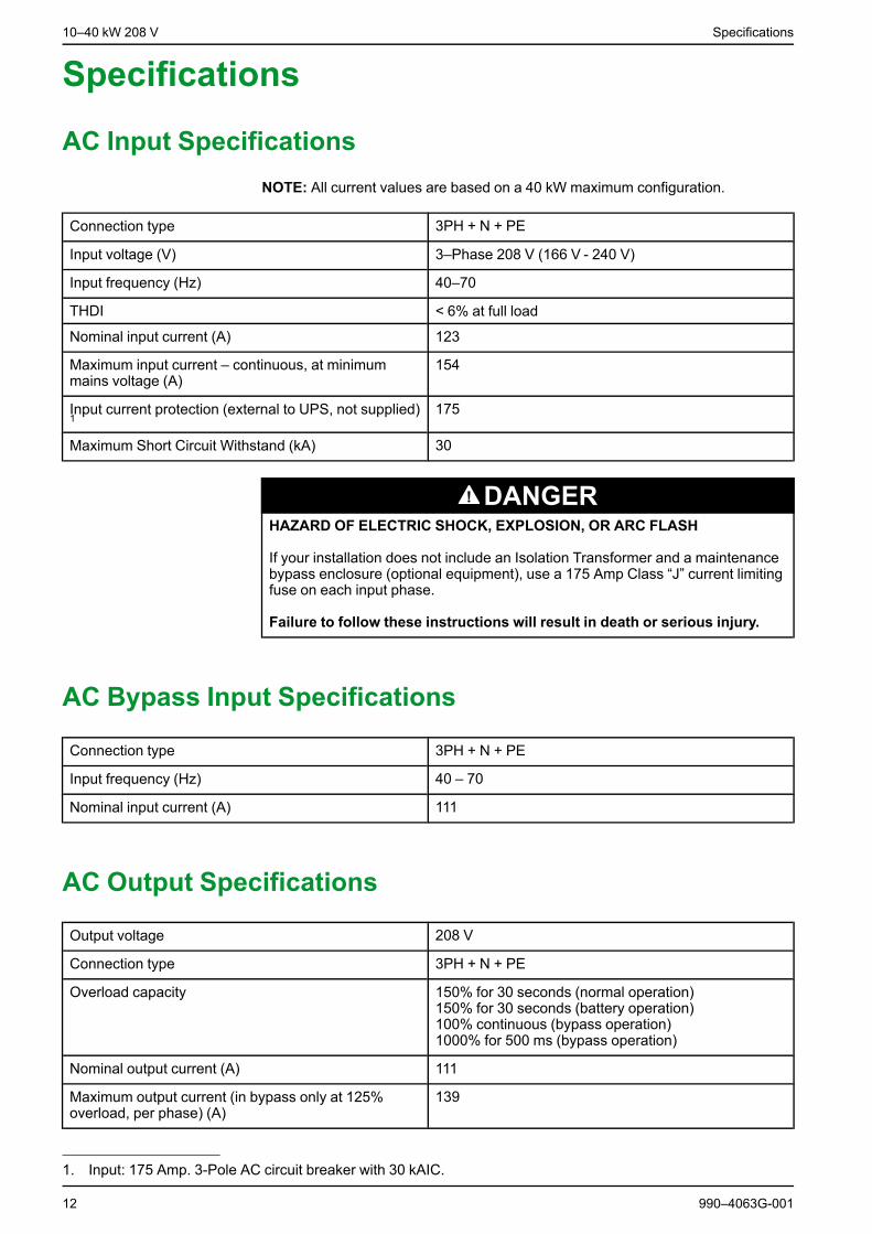
AC Input SpecificationsNOTE: All current values are based on a 40 kW maximum configuration.
Connection type 3PH + N + PE
Input voltage (V) 3–Phase 208 V (166 V - 240 V)
Input frequency (Hz) 40–70
THDI < 6% at full load
Nominal input current (A) 123
Maximum input current – continuous, at minimummains voltage (A)
154
Input current protection (external to UPS, not supplied)1
175
Maximum Short Circuit Withstand (kA) 30
DANGERHAZARD OF ELECTRIC SHOCK, EXPLOSION, OR ARC FLASH
If your installation does not include an Isolation Transformer and a maintenancebypass enclosure (optional equipment), use a 175 Amp Class “J” current limitingfuse on each input phase.
Failure to follow these instructions will result in death or serious injury.
AC Bypass Input Specifications
Connection type 3PH + N + PE
Input frequency (Hz) 40 – 70
Nominal input current (A) 111
AC Output Specifications
Output voltage 208 V
Connection type 3PH + N + PE
Overload capacity 150% for 30 seconds (normal operation)150% for 30 seconds (battery operation)100% continuous (bypass operation)1000% for 500 ms (bypass operation)
Nominal output current (A) 111
Maximum output current (in bypass only at 125%overload, per phase) (A)
139
12 990–4063G-001
1. Input: 175 Amp. 3-Pole AC circuit breaker with 30 kAIC.
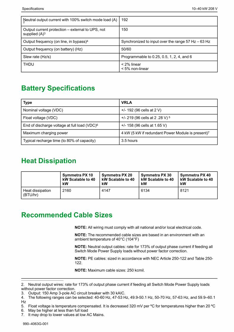
Specifications 10–40 kW 208 V
Neutral output current with 100% switch mode load (A)2
192
Output current protection – external to UPS, notsupplied (A)3
150
Output frequency (on line, in bypass)4 Synchronized to input over the range 57 Hz – 63 Hz
Output frequency (on battery) (Hz) 50/60
Slew rate (Hz/s) Programmable to 0.25, 0.5, 1, 2, 4, and 6
THDU < 2% linear< 5% non-linear
Battery Specifications
Type VRLA
Nominal voltage (VDC) +/- 192 (96 cells at 2 V)
Float voltage (VDC) +/- 219 (96 cells at 2 .28 V) 5
End of discharge voltage at full load (VDC)6 +/- 158 (96 cells at 1.65 V)
Maximum charging power 4 kW (5 kW if redundant Power Module is present)7
Typical recharge time (to 80% of capacity) 3.5 hours
Heat Dissipation
Symmetra PX 10kW Scalable to 40kW
Symmetra PX 20kW Scalable to 40kW
Symmetra PX 30kW Scalable to 40kW
Symmetra PX 40kW Scalable to 40kW
Heat dissipation(BTU/hr)
2160 4147 6134 8121
Recommended Cable SizesNOTE: All wiring must comply with all national and/or local electrical code.
NOTE: The recommended cable sizes are based in an environment with anambient temperature of 40°C (104°F)
NOTE: Neutral output cables: rate for 173% of output phase current if feeding allSwitch Mode Power Supply loads without power factor correction.
NOTE: PE cables: sized in accordance with NEC Article 250-122 and Table 250-122.
NOTE: Maximum cable sizes: 250 kcmil.
990–4063G-001
2. Neutral output wires: rate for 173% of output phase current if feeding all Switch Mode Power Supply loadswithout power factor correction.3. Output: 150 Amp 3-pole AC circuit breaker with 30 kAIC.4. The following ranges can be selected: 40-60 Hz, 47-53 Hz, 49.9-50.1 Hz, 50-70 Hz, 57-63 Hz, and 59.9–60.1Hz5. Float voltage is temperature compensated. It is decreased 320 mV per ºC for temperatures higher than 20 ºC6. May be higher at less than full load7. It may drop to lower values at low AC Mains.

10–40 kW 208 V Specifications
Input cable 2/0 AWG 90 °C (194°F) rated copper wire.
Output cable 1/0 AWG 90 °C (194°F) rated copper wire
Recommended Cable Logs and Crimping Tool
Recommended cable lugs and crimping tools. Manufacturer: FramatomeConnectors International (FCI).
Cable Size (AWG) Terminal bolt diameter: 8 mm
Cable Lug Type Crimping Tool Die
8 YA8CL2TC38 MD7-34R W8CVT
6 YA6CL2TC38 MD7-34R W5CVT
4 YA4CL2TC38 MD7-34R W4CVT
3 YA3CL2TC38 Y35 U3CRT
2 YA2CL2TC38 MD7-34R W2CVT
1 YA1CL2TC38 MD7-34R W1CVT
1/0 YA25CL2TC38 MD7-34R W25VT
2/0 YA26CL2TC38 MD7-34R W26VT
3/0 YA27CL2TC38 MD7-34R W27VT
4/0 YA28CL2TC38 MD7-34R W28VT
Overcurrent Protective Devices in Single Systems
Symmetra PX 40 kW
Utility/mains input 175 Amp 3-Pole AC circuit breaker with 30 kAIC8
Output 150 Amp 3-pole AC circuit breaker with 30 kAIC
14 990–4063G-001
8. If your installation does not include an isolation transformer and a maintenance bypass enclosure (option),use a 175 Amp class “J” current limiting fuse on each input phase.
Mechanical Assembly 10–40 kW 208 V
Mechanical Assembly1. Prepare UPS and modular battery cabinets (if present) for cables by following
Prepare for Cables, page 15.
2. Connect the Power Cables, page 19.
3. Connect the EPO, page 21.
4. Connect Communication Cables, page 24.
5. In installations with modular battery cabinet(s): Install Modular BatteryCabinet (Option), page 27.
6. Install Maintenance Bypass Enclosure (Option), page 30.
7. Level all cabinets with the leveling feet and a bubble level.
Prepare for Cables
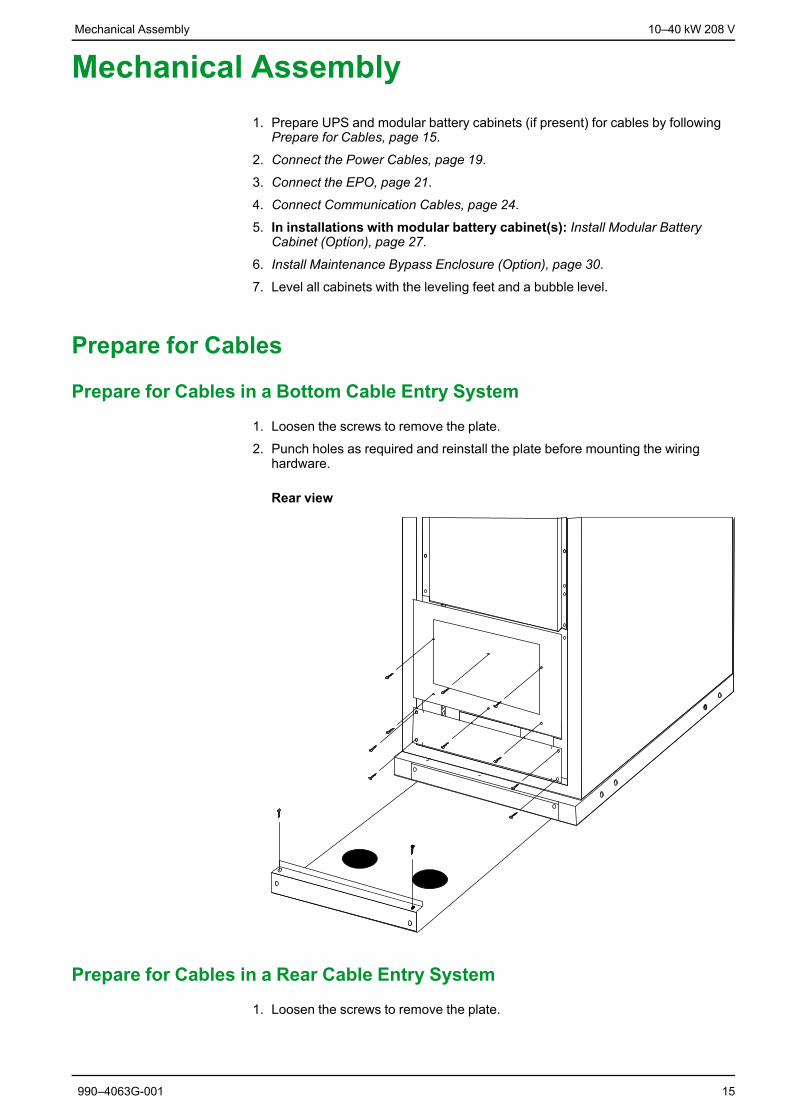
Prepare for Cables in a Bottom Cable Entry System
1. Loosen the screws to remove the plate.
2. Punch holes as required and reinstall the plate before mounting the wiringhardware.
Rear view
Prepare for Cables in a Rear Cable Entry System
1. Loosen the screws to remove the plate.
990–4063G-001 15

10–40 kW 208 V Mechanical Assembly
2. Punch holes as required and reinstall the plate before mounting the wiringhardware.
Rear view of UPS
Rearrange Side Panels for Line-Up and Match Modular Battery Cabinets
DANGERHAZARD OF ELECTRIC SHOCK, EXPLOSION OR ARC FLASH
Remove and reinstall the PE cable connected to the cabinet side panels whenrearranging the side panels. Use a 13 mm wrench.
Failure to follow these instructions will result in death or serious injury.
16 990–4063G-001
Mechanical Assembly 10–40 kW 208 V
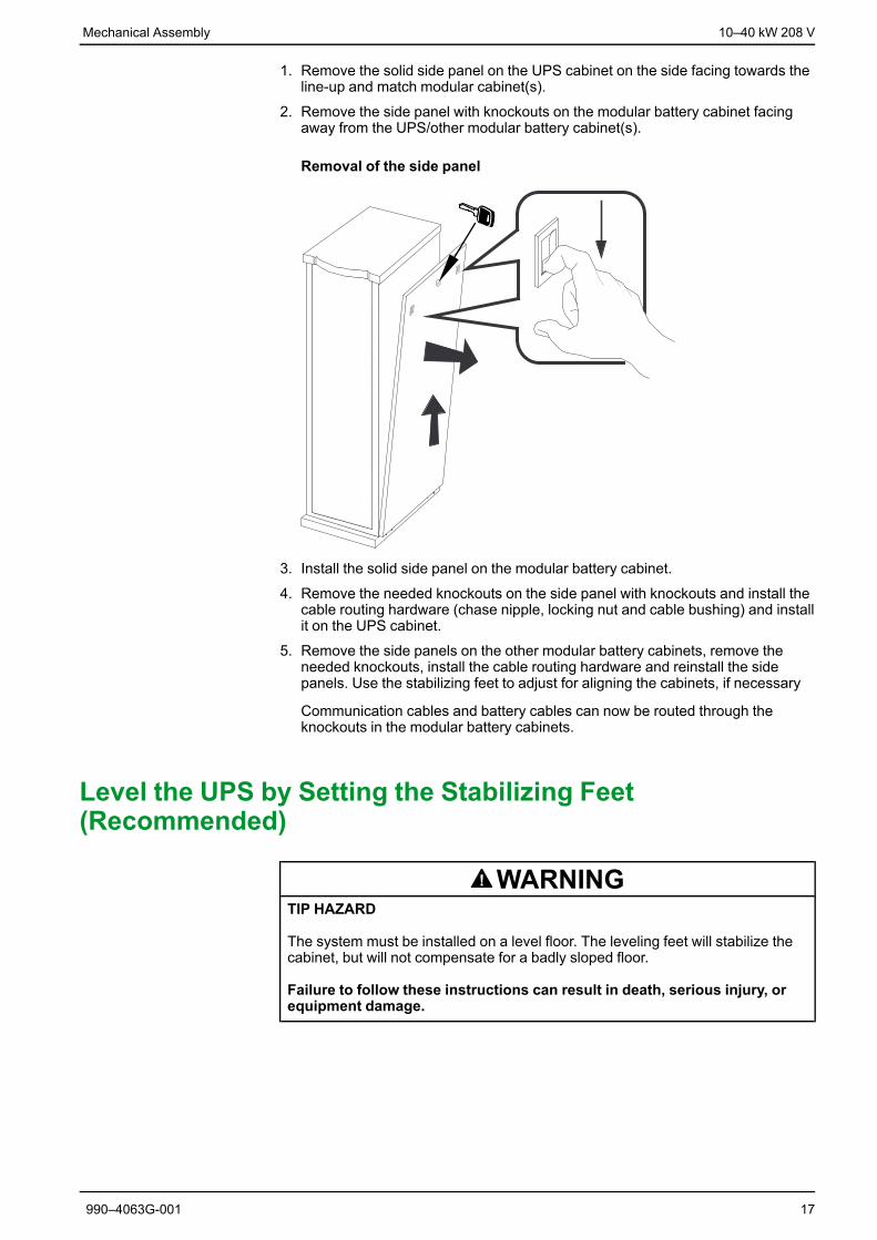
1. Remove the solid side panel on the UPS cabinet on the side facing towards theline-up and match modular cabinet(s).
2. Remove the side panel with knockouts on the modular battery cabinet facingaway from the UPS/other modular battery cabinet(s).
Removal of the side panel
3. Install the solid side panel on the modular battery cabinet.
4. Remove the needed knockouts on the side panel with knockouts and install thecable routing hardware (chase nipple, locking nut and cable bushing) and installit on the UPS cabinet.
5. Remove the side panels on the other modular battery cabinets, remove theneeded knockouts, install the cable routing hardware and reinstall the sidepanels. Use the stabilizing feet to adjust for aligning the cabinets, if necessary
Communication cables and battery cables can now be routed through theknockouts in the modular battery cabinets.
Level the UPS by Setting the Stabilizing Feet(Recommended)
WARNINGTIP HAZARD
The system must be installed on a level floor. The leveling feet will stabilize thecabinet, but will not compensate for a badly sloped floor.
Failure to follow these instructions can result in death, serious injury, orequipment damage.
990–4063G-001 17

10–40 kW 208 V Mechanical Assembly
1. When the electrical wiring has been completed, secure the UPS in its finaloperating position.
2. Use a 13/14-mm wrench (shipped with UPS) to adjust all 4 stabilizing feet untilpads make solid contact with the floor.
3. Adjust the stabilizing feet to level from front to back and left to right.
WARNINGTIP HAZARD
Do not move the cabinet after the leveling feet have been lowered.
Failure to follow these instructions can result in death, serious injury, orequipment damage.
18 990–4063G-001
Connect the Power Cables 10–40 kW 208 V
Connect the Power Cables
DANGERHAZARD OF ELECTRIC SHOCK, EXPLOSION OR ARC FLASH
Ensure clockwise phase rotation and neutral location.
Failure to follow these instructions will result in death or serious injury.
DANGERHAZARD OF ELECTRIC SHOCK, EXPLOSION OR ARC FLASH
Power terminal lug diameter is 8 mm and torque value is 6 Nm.
Failure to follow these instructions will result in death or serious injury.
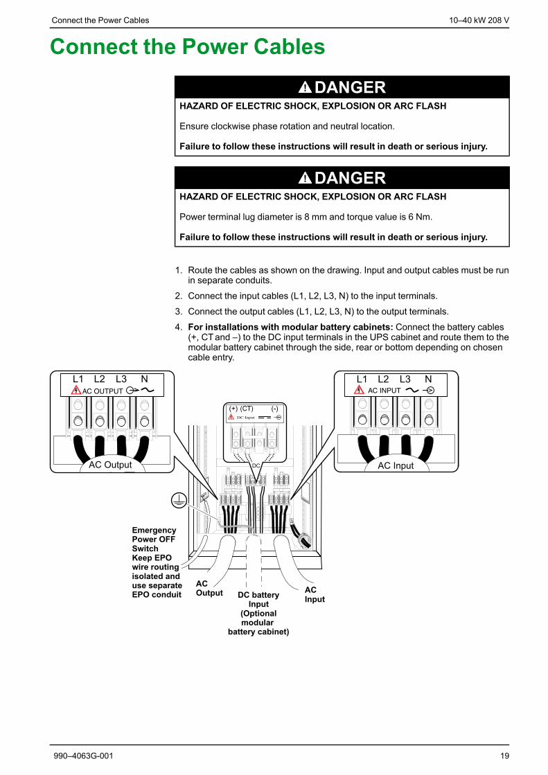
1. Route the cables as shown on the drawing. Input and output cables must be runin separate conduits.
2. Connect the input cables (L1, L2, L3, N) to the input terminals.
3. Connect the output cables (L1, L2, L3, N) to the output terminals.
4. For installations with modular battery cabinets: Connect the battery cables(+, CTand –) to the DC input terminals in the UPS cabinet and route them to themodular battery cabinet through the side, rear or bottom depending on chosencable entry.
990–4063G-001 19

10–40 kW 208 V Connect the Power Cables
5. Connect the PE cable.
20 990–4063G-001

Connect the EPO 10–40 kW 208 V
Connect the EPOThe UPS must be connected to either a dry contact or a 24 VDC EmergencyPower Off (EPO) switch.
The EPO circuit is considered a Class 2 and SELV (Safety Extra Low Voltage). ASELV circuit is isolated from primary circuitry through an isolating transformer anddesigned so that under normal conditions, the voltage is limited to 42.4 VAC peakor 60 VDC. SELVand Class 2 circuits must be isolated from all primary circuitry. Donot connect any circuit to the EPO terminal block unless it can be confirmed thatthe circuit is SELV or Class 2.
For installations in the US:• CL2 Class 2 cable for general purpose use
• CL2P Plenum cable for use in vertical shaft or from floor to floor
• CL2R Racer cable for use in dwellings and raceways
• CL2X Limited use cable for dwellings and raceways
For installation in Canada:• CL2R-Certified, type ELC (Extra-Low-Voltage Control Cable)
• CL2X-Certified, type ELC (Extra-Low-Voltage Control Cable)
1. Route the EPO cable through a separate conduit in the rear of the cabinet andkeep the EPO wire routing isolated from the power cables.
990–4063G-001 21
10–40 kW 208 V Connect the EPO
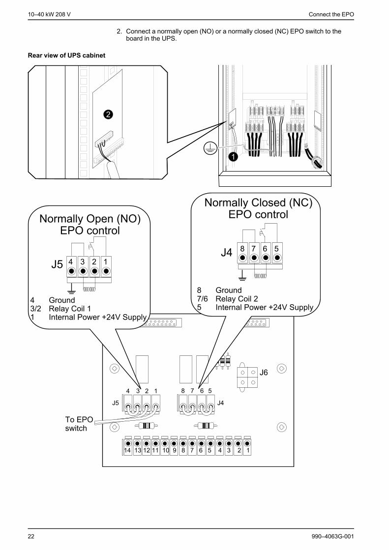
2. Connect a normally open (NO) or a normally closed (NC) EPO switch to theboard in the UPS.
Rear view of UPS cabinet
22 990–4063G-001

Connect the EPO 10–40 kW 208 V
EPOWiring Options
A. Dry Normally Open contacts
B. +24V Normally Open (remove jumper)
C. Dry Normally Closed contacts (remove jumper)
D. +24V Normally Closed (remove jumper)
990–4063G-001 23

10–40 kW 208 V Connect Communication Cables
Connect Communication Cables
DANGERHAZARD OF ELECTRIC SHOCK, EXPLOSION OR ARC FLASH
Ensure total power off before removing the side panel.
Failure to follow these instructions will result in death or serious injury.
NOTE: Use 20–foot standard Cat data cable (supplied). If the cable length isinadequate, a longer Cat 5 cable, or couplers, can be used (not supplied)..
NOTE: If bottom cable entry is required, follow steps 1 to 5 below to gain access tothe communication cables. If not, proceed to step 6.
Front view of UPS
1. Unlock the right-side panel using the key.
2. Depress the latches.
3. Pull out the panel.
4. Lift the panel at an angle away from the cabinet.
5. Route the communication cables through the front holes of the cabinets. Exitthe cabinets from the bottom or top as required.
24 990–4063G-001
Connect Communication Cables 10–40 kW 208 V
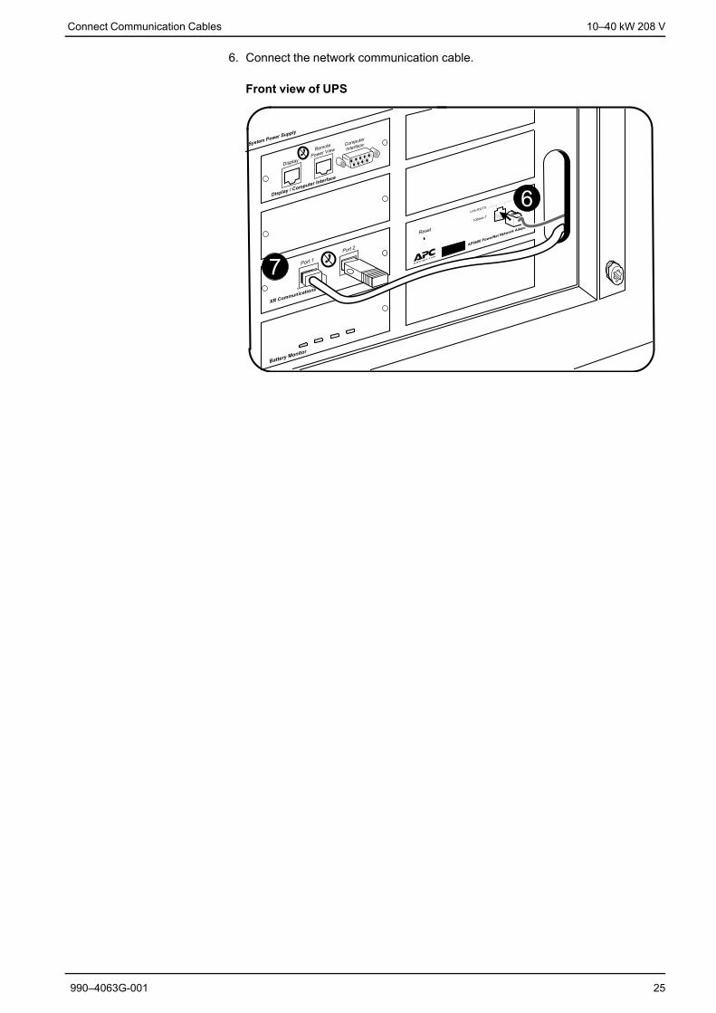
6. Connect the network communication cable.
Front view of UPS
990–4063G-001 25

10–40 kW 208 V Connect Communication Cables
7. Only in installations with modular battery cabinets: Route thecommunication cable from XR Communications port 2 in the first modularbattery cabinet to the UPS XR Communications port 1 (for remote modularbattery cabinets the length of the signal must not exceed 50 m). The side panelof the modular battery cabinet is removed for cable wiring as in steps 1–5.
Front view of modular battery cabinet
8. Only in installations with modular battery cabinets: Route thecommunication cable from XR Communications port 1 in each modular batterycabinet to XR Communications port 2 in the next modular battery cabinet.Remove the terminator when necessary. Insert the terminator from the cableinto the unused communication port on the last modular battery cabinet.
9. Reinstall and lock the side panels on the cabinets after finishing cable routing.
26 990–4063G-001
Install Modular Battery Cabinet (Option) 10–40 kW 208 V
Install Modular Battery Cabinet (Option)
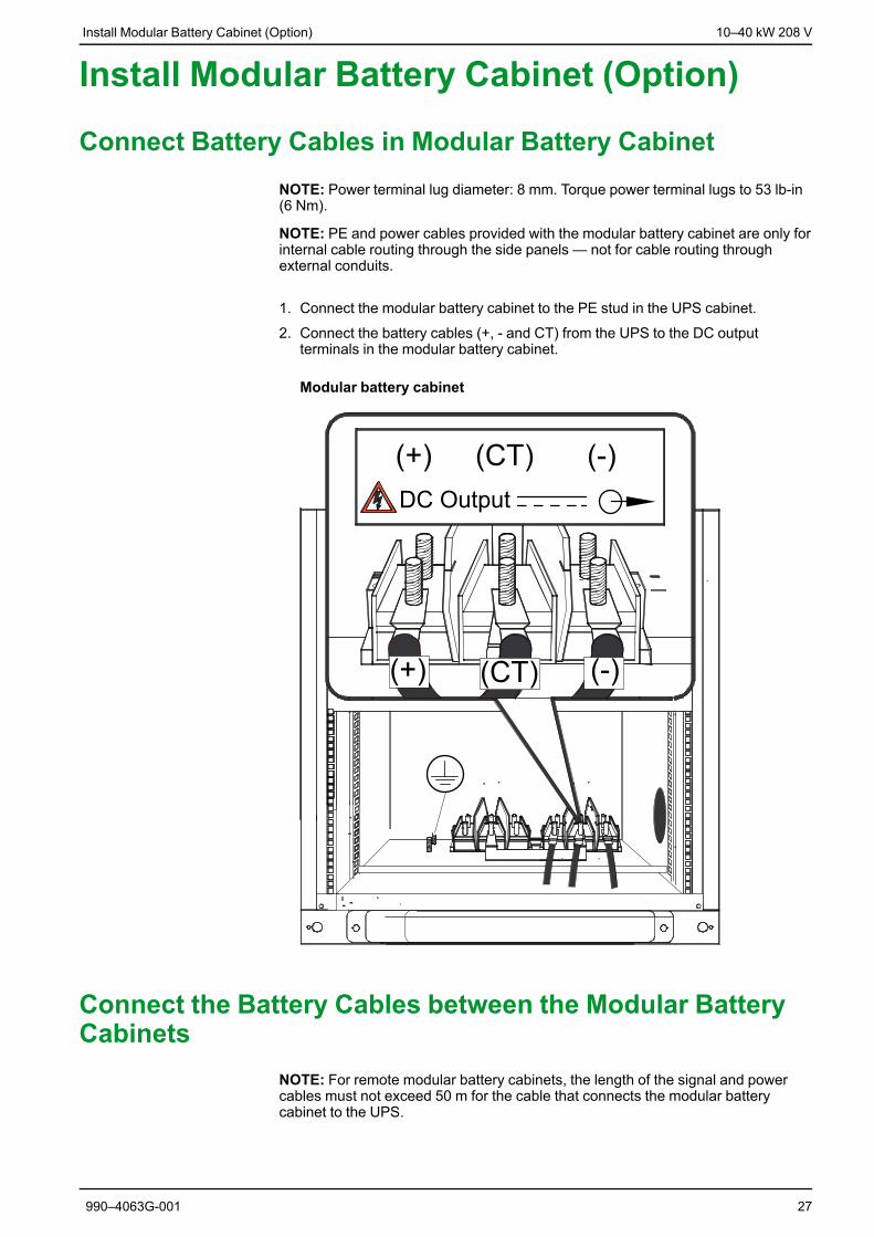
Connect Battery Cables in Modular Battery CabinetNOTE: Power terminal lug diameter: 8 mm. Torque power terminal lugs to 53 lb-in(6 Nm).
NOTE: PE and power cables provided with the modular battery cabinet are only forinternal cable routing through the side panels — not for cable routing throughexternal conduits.
1. Connect the modular battery cabinet to the PE stud in the UPS cabinet.
2. Connect the battery cables (+, - and CT) from the UPS to the DC outputterminals in the modular battery cabinet.
Modular battery cabinet
Connect the Battery Cables between the Modular BatteryCabinets
NOTE: For remote modular battery cabinets, the length of the signal and powercables must not exceed 50 m for the cable that connects the modular batterycabinet to the UPS.
990–4063G-001 27

10–40 kW 208 V Install Modular Battery Cabinet (Option)
1. Connect the battery cables from the DC output terminals in modular batterycabinet 2 to the DC input terminals in modular battery cabinet 1.
Modular battery cabinet 1
2. Repeat for modular battery cabinet 3 and 4, if applicable.
3. Connect the PE cable from the UPS to the modular battery cabinet (closest tothe UPS).
28 990–4063G-001
Install Modular Battery Cabinet (Option) 10–40 kW 208 V
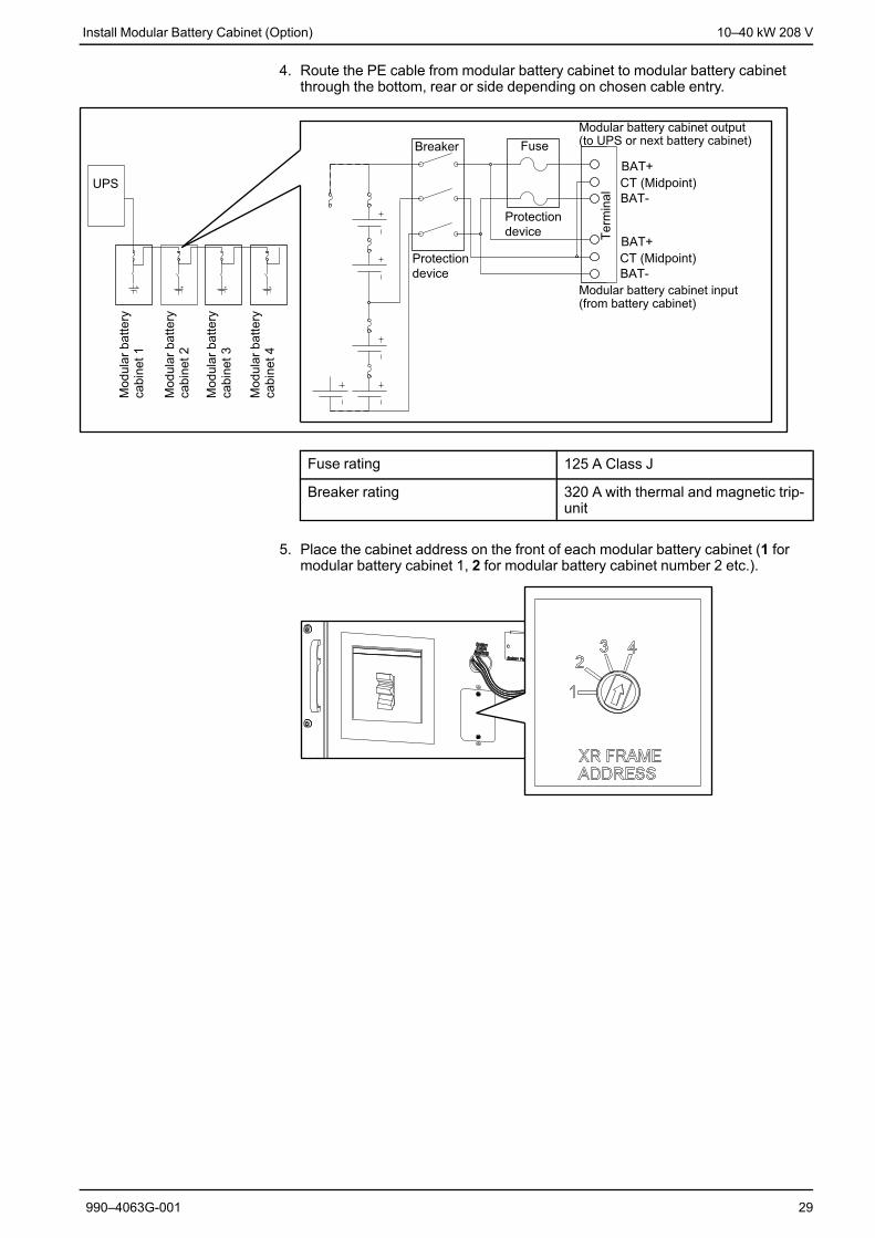
4. Route the PE cable from modular battery cabinet to modular battery cabinetthrough the bottom, rear or side depending on chosen cable entry.
Fuse rating 125 A Class J
Breaker rating 320 A with thermal and magnetic trip-unit
5. Place the cabinet address on the front of each modular battery cabinet (1 formodular battery cabinet 1, 2 for modular battery cabinet number 2 etc.).
990–4063G-001 29
10–40 kW 208 VInstall Maintenance Bypass Enclosure
(Option)
Install Maintenance Bypass Enclosure(Option)
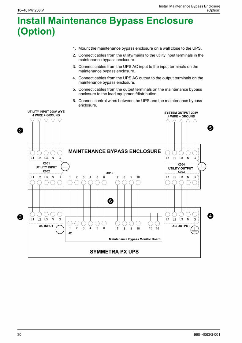
1. Mount the maintenance bypass enclosure on a wall close to the UPS.
2. Connect cables from the utility/mains to the utility input terminals in themaintenance bypass enclosure.
3. Connect cables from the UPS AC input to the input terminals on themaintenance bypass enclosure.
4. Connect cables from the UPS AC output to the output terminals on themaintenance bypass enclosure.
5. Connect cables from the output terminals on the maintenance bypassenclosure to the load equipment/distribution.
6. Connect control wires between the UPS and the maintenance bypassenclosure.
30 990–4063G-001

10–40 kW 208 VInstall Maintenance Bypass Enclosure
(Option)

Schneider Electric35 rue Joseph Monier92500 Rueil MalmasonFrance
+ 33 (0) 1 41 29 70 00www.schneider-electric.com
As standards, specifications, and design change fromtime to time, please ask for confirmation of theinformation given in this publication.
© 2013 – 2014 Schneider Electric. All rights reserved.990–4063G-001