symmetricwaterbomb rspa.royalsocietypublishing.org...
TRANSCRIPT

rspa.royalsocietypublishing.org
ResearchCite this article: Chen Y, Feng H, Ma J, PengR, You Z. 2016 Symmetric waterbomb origami.Proc. R. Soc. A 472: 20150846.http://dx.doi.org/10.1098/rspa.2015.0846
Received: 11 December 2015Accepted: 5 May 2016
Subject Areas:mechanical engineering, structuralengineering
Keywords:waterbomb base, waterbomb tessellation,rigid origami, thick-panel origami
Author for correspondence:Zhong Youe-mail: [email protected]
Symmetric waterbomborigamiYan Chen1,2, Huijuan Feng1, Jiayao Ma1, Rui Peng1 and
Zhong You1,3
1School of Mechanical Engineering, Tianjin University,92 Weijin Road, Tianjin 300072, People’s Republic of China2Key Laboratory of Mechanism Theory and Equipment Design ofMinistry of Education, Tianjin University, Tianjin 300072,People’s Republic of China3Department of Engineering Science, University of Oxford,Parks Road, Oxford OX1 3PJ, UK
YC, 0000-0002-4742-6944; ZY, 0000-0002-5286-7218
The traditional waterbomb origami, produced froma pattern consisting of a series of vertices where sixcreases meet, is one of the most widely used origamipatterns. From a rigid origami viewpoint, it generallyhas multiple degrees of freedom, but when thepattern is folded symmetrically, the mobility reducesto one. This paper presents a thorough kinematicinvestigation on symmetric folding of the waterbombpattern. It has been found that the pattern canhave two folding paths under certain circumstance.Moreover, the pattern can be used to fold thick panels.Not only do the additional constraints imposed tofold the thick panels lead to single degree of freedomfolding, but the folding process is also kinematicallyequivalent to the origami of zero-thickness sheets. Thefindings pave the way for the pattern being readilyused to fold deployable structures ranging from flatroofs to large solar panels.
1. IntroductionThe waterbomb is a traditional origami (http://www.britishorigami.info/academic/lister/waterbomb.php).Commonly, two terms are related to it: waterbombbases and waterbomb tessellations. There are two typesof waterbomb bases: the eight-crease base and thesix-crease base. The former is made from a squaresheet of paper consisting of eight alternating mountainand valley creases around a central vertex (figure 1a).One of its typical tessellations is produced by four
2016 The Author(s) Published by the Royal Society. All rights reserved.
on June 8, 2016http://rspa.royalsocietypublishing.org/Downloaded from

2
rspa.royalsocietypublishing.orgProc.R.Soc.A472:20150846
...................................................
(b)(a) (c)
(d ) (e) ( f )
Figure 1. Two waterbomb bases and their tessellations. (a) The eight-crease waterbomb base; (b) one of its tessellationsforming the Resch pattern; (c) partially folded Resch pattern model; (d) the six-crease waterbomb base; (e) its tessellationin unfolded and folded states and (f ) the tessellation can also be used to form a tube.
such bases tiling around a smaller square forming the square Resch pattern (figure 1b,c). Thelatter, consisting of two mountain and four valley creases shown in figure 1d, is more commonlyknown, and its tessellations range from a flat-foldable surface to a deformable tube known as themagic origami ball (figure 1e,f ).
Both waterbomb origami structures were extensively investigated in the past. For instance,Hanna et al. and Bowen et al. established the bistable and dynamic model of the eight-creasewaterbomb base [1,2]. Tachi et al. [3] worked on the rigidity of a six-crease origami tessellationwith multiple degrees of freedom to achieve an adaptive freeform surface. On the application side,the first origami stent was made from the waterbomb tube aimed to achieve a large deployableratio [4]. A worm robot [5] and a deformable wheel robot [6] were also proposed based on themagic origami ball.
In this paper, the focus is drawn on the six-crease waterbomb tessellation. Owing to its largedeployable ratio between expanded and packaged states, it can be potentially used to fold largeflat roofs and space solar panels. Although the waterbomb pattern is of multiple degrees offreedom, the symmetric folding is often preferred in most of research or artwork, which is doneby constraining it with symmetric conditions and then controlling the motion to reach an idealflat-foldable state. This is not easy in practice due to the fact that in rigid origami, the six-creasewaterbomb base itself is a spherical 6R linkage with three degrees of freedom [7], thus the numberof degrees of freedom for the pattern could increase significantly if the pattern consists of a largenumber of such bases.
The waterbomb pattern is primarily created for zero-thickness sheets just like all of the origamipatterns. Yet, in most of the practical engineering applications, the thickness of the material cannotsimply be ignored. Various methods have been proposed to fold thick panel. In one instance,tapered surfaces are used to fold a thick panel using the Miura-ori of zero-thickness sheet [8],whereas in the other, offsets at the edge of the panels were introduced to implement foldingof thick panels using the square-twist origami pattern [9]. More recent research suggested toreplace folds with two parallel ones to accommodate the thickness of materials [10]. In all ofthe above methods, the fundamental kinematic model in which origami is treated as a series ofinterconnected spherical linkages remained. Different from the above methods, the authors ofthis paper have also proposed an approach in which the fold lines were only allowed to be placedon the top or the bottom of flat thick panels. As a result, the spherical linkage assembly for theorigami of zero-thickness sheet is replaced by an assembly of spatial linkages. We have proved
on June 8, 2016http://rspa.royalsocietypublishing.org/Downloaded from

3
rspa.royalsocietypublishing.orgProc.R.Soc.A472:20150846
...................................................
Table 1. Nomenclature.a. . . . . . . . . . . . . . . . . . . . . . . . . . . . . . . . . . . . . . . . . . . . . . . . . . . . . . . . . . . . . . . . . . . . . . . . . . . . . . . . . . . . . . . . . . . . . . . . . . . . . . . . . . . . . . . . . . . . . . . . . . . . . . . . . . . . . . . . . . . . . . . . . . . . . . . . . . . . . . . . . . . . . . . . . . . . . . . . . . . . . . . . . . . . . . . . . . . . . . . . . .
zi coordinate axis of crease i or revolute joint i. . . . . . . . . . . . . . . . . . . . . . . . . . . . . . . . . . . . . . . . . . . . . . . . . . . . . . . . . . . . . . . . . . . . . . . . . . . . . . . . . . . . . . . . . . . . . . . . . . . . . . . . . . . . . . . . . . . . . . . . . . . . . . . . . . . . . . . . . . . . . . . . . . . . . . . . . . . . . . . . . . . . . . . . . . . . . . . . . . . . . . . . . . . . . . . . . . . . . . . . . .
xi coordinate axis common normal from zi−1 to zi. . . . . . . . . . . . . . . . . . . . . . . . . . . . . . . . . . . . . . . . . . . . . . . . . . . . . . . . . . . . . . . . . . . . . . . . . . . . . . . . . . . . . . . . . . . . . . . . . . . . . . . . . . . . . . . . . . . . . . . . . . . . . . . . . . . . . . . . . . . . . . . . . . . . . . . . . . . . . . . . . . . . . . . . . . . . . . . . . . . . . . . . . . . . . . . . . . . . . . . . . .
αi(i+1) angle of rotation from zi to zi+1 about axis xi+1, also known as the twist of link i(i + 1). . . . . . . . . . . . . . . . . . . . . . . . . . . . . . . . . . . . . . . . . . . . . . . . . . . . . . . . . . . . . . . . . . . . . . . . . . . . . . . . . . . . . . . . . . . . . . . . . . . . . . . . . . . . . . . . . . . . . . . . . . . . . . . . . . . . . . . . . . . . . . . . . . . . . . . . . . . . . . . . . . . . . . . . . . . . . . . . . . . . . . . . . . . . . . . . . . . . . . . . . .
α,β design angular parameters of the waterbomb origami pattern. . . . . . . . . . . . . . . . . . . . . . . . . . . . . . . . . . . . . . . . . . . . . . . . . . . . . . . . . . . . . . . . . . . . . . . . . . . . . . . . . . . . . . . . . . . . . . . . . . . . . . . . . . . . . . . . . . . . . . . . . . . . . . . . . . . . . . . . . . . . . . . . . . . . . . . . . . . . . . . . . . . . . . . . . . . . . . . . . . . . . . . . . . . . . . . . . . . . . . . . . .
Qi(i+1) 3 × 3 transformation matrix between the coordinate system of link (i − 1)i and that of link i(i + 1)for spherical linkages
. . . . . . . . . . . . . . . . . . . . . . . . . . . . . . . . . . . . . . . . . . . . . . . . . . . . . . . . . . . . . . . . . . . . . . . . . . . . . . . . . . . . . . . . . . . . . . . . . . . . . . . . . . . . . . . . . . . . . . . . . . . . . . . . . . . . . . . . . . . . . . . . . . . . . . . . . . . . . . . . . . . . . . . . . . . . . . . . . . . . . . . . . . . . . . . . . . . . . . . . . .
δi angle of rotation from xi to xi+1 about axis zi in the vertex D of the origami waterbomb pattern, also known asthe revolute variable of joint i
. . . . . . . . . . . . . . . . . . . . . . . . . . . . . . . . . . . . . . . . . . . . . . . . . . . . . . . . . . . . . . . . . . . . . . . . . . . . . . . . . . . . . . . . . . . . . . . . . . . . . . . . . . . . . . . . . . . . . . . . . . . . . . . . . . . . . . . . . . . . . . . . . . . . . . . . . . . . . . . . . . . . . . . . . . . . . . . . . . . . . . . . . . . . . . . . . . . . . . . . . .
ϕi dihedral angle between link (i − 1)i and link i(i + 1) in the vertex D of the waterbomb origami pattern. . . . . . . . . . . . . . . . . . . . . . . . . . . . . . . . . . . . . . . . . . . . . . . . . . . . . . . . . . . . . . . . . . . . . . . . . . . . . . . . . . . . . . . . . . . . . . . . . . . . . . . . . . . . . . . . . . . . . . . . . . . . . . . . . . . . . . . . . . . . . . . . . . . . . . . . . . . . . . . . . . . . . . . . . . . . . . . . . . . . . . . . . . . . . . . . . . . . . . . . . .
ωi angle of rotation from xi to xi+1 about axis zi in the vertexW of the waterbomb origami pattern, also known asthe revolute variable of joint i
. . . . . . . . . . . . . . . . . . . . . . . . . . . . . . . . . . . . . . . . . . . . . . . . . . . . . . . . . . . . . . . . . . . . . . . . . . . . . . . . . . . . . . . . . . . . . . . . . . . . . . . . . . . . . . . . . . . . . . . . . . . . . . . . . . . . . . . . . . . . . . . . . . . . . . . . . . . . . . . . . . . . . . . . . . . . . . . . . . . . . . . . . . . . . . . . . . . . . . . . . .
φi dihedral angle between link (i − 1)i and link i(i + 1) in the vertexW of the waterbomb origami pattern. . . . . . . . . . . . . . . . . . . . . . . . . . . . . . . . . . . . . . . . . . . . . . . . . . . . . . . . . . . . . . . . . . . . . . . . . . . . . . . . . . . . . . . . . . . . . . . . . . . . . . . . . . . . . . . . . . . . . . . . . . . . . . . . . . . . . . . . . . . . . . . . . . . . . . . . . . . . . . . . . . . . . . . . . . . . . . . . . . . . . . . . . . . . . . . . . . . . . . . . . .
aDi(i+1) normal distance between zi and zi+1, also known as the link length of link i(i + 1) in the vertex D of thethick-panel waterbomb pattern or the panel thickness
. . . . . . . . . . . . . . . . . . . . . . . . . . . . . . . . . . . . . . . . . . . . . . . . . . . . . . . . . . . . . . . . . . . . . . . . . . . . . . . . . . . . . . . . . . . . . . . . . . . . . . . . . . . . . . . . . . . . . . . . . . . . . . . . . . . . . . . . . . . . . . . . . . . . . . . . . . . . . . . . . . . . . . . . . . . . . . . . . . . . . . . . . . . . . . . . . . . . . . . . . .
aWi(i+1) normal distance between zi and zi+1, also known as the link length of link i(i + 1) in the vertexW of thethick-panel waterbomb pattern or the panel thickness
. . . . . . . . . . . . . . . . . . . . . . . . . . . . . . . . . . . . . . . . . . . . . . . . . . . . . . . . . . . . . . . . . . . . . . . . . . . . . . . . . . . . . . . . . . . . . . . . . . . . . . . . . . . . . . . . . . . . . . . . . . . . . . . . . . . . . . . . . . . . . . . . . . . . . . . . . . . . . . . . . . . . . . . . . . . . . . . . . . . . . . . . . . . . . . . . . . . . . . . . . .
RDi normal distance between xi and xi+1 also known as the offset of joint i in the vertex D of the thick-panelwaterbomb pattern
. . . . . . . . . . . . . . . . . . . . . . . . . . . . . . . . . . . . . . . . . . . . . . . . . . . . . . . . . . . . . . . . . . . . . . . . . . . . . . . . . . . . . . . . . . . . . . . . . . . . . . . . . . . . . . . . . . . . . . . . . . . . . . . . . . . . . . . . . . . . . . . . . . . . . . . . . . . . . . . . . . . . . . . . . . . . . . . . . . . . . . . . . . . . . . . . . . . . . . . . . .
RWi normal distance between xi and xi+1, also known as the offset of joint i in the vertexW of the thick-panelwaterbomb pattern
. . . . . . . . . . . . . . . . . . . . . . . . . . . . . . . . . . . . . . . . . . . . . . . . . . . . . . . . . . . . . . . . . . . . . . . . . . . . . . . . . . . . . . . . . . . . . . . . . . . . . . . . . . . . . . . . . . . . . . . . . . . . . . . . . . . . . . . . . . . . . . . . . . . . . . . . . . . . . . . . . . . . . . . . . . . . . . . . . . . . . . . . . . . . . . . . . . . . . . . . . .
Ti(i+1) 4 × 4 transformation matrix between the coordinate system of link (i − 1)i and that of link i(i + 1). . . . . . . . . . . . . . . . . . . . . . . . . . . . . . . . . . . . . . . . . . . . . . . . . . . . . . . . . . . . . . . . . . . . . . . . . . . . . . . . . . . . . . . . . . . . . . . . . . . . . . . . . . . . . . . . . . . . . . . . . . . . . . . . . . . . . . . . . . . . . . . . . . . . . . . . . . . . . . . . . . . . . . . . . . . . . . . . . . . . . . . . . . . . . . . . . . . . . . . . . .
a thickness parameter for thick-panel waterbomb pattern, also the thickness of link 23 in the vertexW of thethick-panel waterbomb pattern
. . . . . . . . . . . . . . . . . . . . . . . . . . . . . . . . . . . . . . . . . . . . . . . . . . . . . . . . . . . . . . . . . . . . . . . . . . . . . . . . . . . . . . . . . . . . . . . . . . . . . . . . . . . . . . . . . . . . . . . . . . . . . . . . . . . . . . . . . . . . . . . . . . . . . . . . . . . . . . . . . . . . . . . . . . . . . . . . . . . . . . . . . . . . . . . . . . . . . . . . . .
μ ratio between the thickness of link 34 and link 23 in the vertexW of the thick-panel waterbomb pattern. . . . . . . . . . . . . . . . . . . . . . . . . . . . . . . . . . . . . . . . . . . . . . . . . . . . . . . . . . . . . . . . . . . . . . . . . . . . . . . . . . . . . . . . . . . . . . . . . . . . . . . . . . . . . . . . . . . . . . . . . . . . . . . . . . . . . . . . . . . . . . . . . . . . . . . . . . . . . . . . . . . . . . . . . . . . . . . . . . . . . . . . . . . . . . . . . . . . . . . . . .
δ′i angle of rotation from xi to xi+1 about axis zi in the vertex D of the thick-panel waterbomb pattern, also known
as the revolute variable of joint i. . . . . . . . . . . . . . . . . . . . . . . . . . . . . . . . . . . . . . . . . . . . . . . . . . . . . . . . . . . . . . . . . . . . . . . . . . . . . . . . . . . . . . . . . . . . . . . . . . . . . . . . . . . . . . . . . . . . . . . . . . . . . . . . . . . . . . . . . . . . . . . . . . . . . . . . . . . . . . . . . . . . . . . . . . . . . . . . . . . . . . . . . . . . . . . . . . . . . . . . . .
ϕ′i dihedral angle between link (i − 1)i and link i(i + 1) in the vertex D of the thick-panel waterbomb pattern
. . . . . . . . . . . . . . . . . . . . . . . . . . . . . . . . . . . . . . . . . . . . . . . . . . . . . . . . . . . . . . . . . . . . . . . . . . . . . . . . . . . . . . . . . . . . . . . . . . . . . . . . . . . . . . . . . . . . . . . . . . . . . . . . . . . . . . . . . . . . . . . . . . . . . . . . . . . . . . . . . . . . . . . . . . . . . . . . . . . . . . . . . . . . . . . . . . . . . . . . . .
ω′i angle of rotation from xi to xi+1 about axis zi in the vertexW of the thick-panel waterbomb pattern, also
known as the revolute variable of joint i. . . . . . . . . . . . . . . . . . . . . . . . . . . . . . . . . . . . . . . . . . . . . . . . . . . . . . . . . . . . . . . . . . . . . . . . . . . . . . . . . . . . . . . . . . . . . . . . . . . . . . . . . . . . . . . . . . . . . . . . . . . . . . . . . . . . . . . . . . . . . . . . . . . . . . . . . . . . . . . . . . . . . . . . . . . . . . . . . . . . . . . . . . . . . . . . . . . . . . . . . .
φ′i dihedral angle between link (i − 1)i and link i(i + 1) in the vertexW of the thick-panel waterbomb pattern
. . . . . . . . . . . . . . . . . . . . . . . . . . . . . . . . . . . . . . . . . . . . . . . . . . . . . . . . . . . . . . . . . . . . . . . . . . . . . . . . . . . . . . . . . . . . . . . . . . . . . . . . . . . . . . . . . . . . . . . . . . . . . . . . . . . . . . . . . . . . . . . . . . . . . . . . . . . . . . . . . . . . . . . . . . . . . . . . . . . . . . . . . . . . . . . . . . . . . . . . . .aThe set-up of coordinates and kinematic parameters for both zero-thickness and thick-panel origami according to Denavit–Hartenberg’s (DH)notation is shown in figure 11 of appendix A.
that not only are the assemblies of such panels foldable, but also they can be folded compactlyunder certain conditions [11].
In this paper, we provide a comprehensive kinematic analysis on foldability of the waterbombtessellation made from the six-crease waterbomb bases of both a zero-thickness sheet and a panelof finite thickness. Kinematically, the folding of a zero-thickness sheet is modelled as spherical6R linkages, whereas that of a thick panel is treated as an assembly of the Bricard linkages.The analysis has revealed a number of very interesting features associated with waterbomborigami, including the existence of two folding paths for general waterbomb origami of zero-thickness sheets when it is folded symmetrically. Moreover, because the Bricard linkages areoverconstrained [12,13], the increase in the number of degrees of freedom occurring for theorigami of zero-thickness sheet does not materialize for thick panels.
on June 8, 2016http://rspa.royalsocietypublishing.org/Downloaded from

4
rspa.royalsocietypublishing.orgProc.R.Soc.A472:20150846
...................................................
The paper is structured as follows. Section 2 presents a detailed analysis on rigid foldability ofthe waterbomb tessellation for zero-thickness sheets. This is followed by the design and kinematicbehaviour of its corresponding thick-panel origami in §3. Comparisons are made in §4 withfurther discussion for potential applications. The nomeclature is given in table 1.
2. Symmetric rigid folding of the waterbomb pattern of zero-thickness sheetConsider a pattern made by tessellating six-crease waterbomb bases (figure 2a). The patternconsists of only two types of vertices, D and W, enlarged in figure 2b,c. The rigid origamifolding around each vertex can be modelled kinematically as a spherical 6R linkage in whichthe creases act as revolute joints and the sheets between creases are rigid links. In general, aspherical 6R linkage is of three degrees of freedom, but this number is reduced to one if onlythe symmetric folding is allowed. In such a way, vertex D is regarded as a spherical 6R linkagewith the geometrical parameters α12 = α34 = α45 = α61 = α, α23 = α56 = π − 2α, where 0 < α ≤ π/2.Imposing the line and plane symmetry conditions, i.e. δ1 = δ4 and δ2 = δ3 = δ5 = δ6, to the closurecondition of the linkage (see appendix A), we can then write the closure equations as
tanδ1
2= − cos α tan
δ2
2and δ1 = δ4, δ2 = δ3 = δ5 = δ6. (2.1)
Similarly, applying the symmetry condition to vertex W, it becomes a plane-symmetric spherical6R linkage with the geometric parameters α12 = α61 = π − α − β, α23 = α56 = β, α34 = α45 = α,where 0 < β ≤ π/2, and
ω5 = ω3 and ω6 = ω2. (2.2a)
To ensure the compatibility of the entire pattern, the kinematic relationship between ω1 and ω3 ofvertex W must be identical to that between δ1 and δ2 of vertex D. Replacing δ1 and δ2 in equation(2.1) with ω1 and ω3, respectively, yields
tanω1
2= − cos α tan
ω3
2. (2.2b)
Now, considering the closure condition of the linkage at W, we obtain two sets of equations. Thefirst set is
tanω2
2= − cos α
cos(α + β)tan
ω3
2(2.3a)
and
ω4 = ω1, (2.3b)
whereas the second one is
tanω2
2= − 2 sin α tan(ω3/2)
sin(β − α) tan2(ω3/2) + sin(α + β), (2.4a)
and
tanω4
2=
tan(ω3/2)(−2 cos α sin2(β − α) tan4(ω3/2) + 4(sin α sin 2β
+ cos α sin(α + β) sin(β − α)) tan2(ω3/2) + sin(α + β)(7 sin β − sin(2α + β)))
2 sin(β − α)(2 sin(α + β) + sin(β − α)) tan4(ω3/2) + 4(cos2(α + β)− cos 2β) tan2(ω3/2) − 2 sin2(α + β)
.
(2.4b)
Together with equations (2.1) and (2.2), the entire set of closure equations of the waterbombpattern has been obtained.
on June 8, 2016http://rspa.royalsocietypublishing.org/Downloaded from

5
rspa.royalsocietypublishing.orgProc.R.Soc.A472:20150846
...................................................
DW
z6
z6
z5
z5
z4
z4
z3
z3
z1
z1
z2
z2
j6j1
j5
f5
f4
f3
f2f6
f1
b ba a
p –a –b p –a –b
j4j3
a
a a
a
p – 2a p – 2a
j2
(b)(a) (c)
Figure 2. Six-crease waterbomb pattern. (a) The general tessellation of six-crease waterbomb pattern; (b) vertex D and itssurrounding creases and (c) vertexW and its surrounding creases.
The kinematic variables, or rotations about each crease, can be replaced by the dihedralangles between adjacent sheets connected by the crease. The relationship between the kinematicvariables and dihedral angels is δ1 = π − ϕ1, δ2 = π + ϕ2, δ3 = π + ϕ3, δ4 = π − ϕ4, δ5 = π + ϕ5,δ6 = π + ϕ6 for vertex D and ω1 = π − φ1, ω2 = π − φ2, ω3 = π + φ3, ω4 = π − φ4, ω5 = π + φ5,ω6 = π − φ6, for vertex W. Thus, the two sets of kinematic relationships of the waterbomb patternpresented by the dihedral angels become
tanφ1
2= 1
cos αtan
φ3
2, (2.5a)
tanφ2
2= cos(α + β)
cos αtan
φ3
2, (2.5b)
φ4 = φ1, φ5 = φ3 φ6 = φ2, (2.5c)
ϕ2 = φ3, (2.5d)
tanϕ1
2= 1
cos αtan
ϕ2
2, ϕ1 = ϕ4, ϕ2 = ϕ3 = ϕ5 = ϕ6 (2.5e)
and
tanφ1
2= 1
cos αtan
φ3
2, (2.6a)
tanφ2
2= sin(α + β) tan2(φ3/2) + sin(β − α)
2 sin α tan(φ3/2), (2.6b)
tanφ4
2=
tan(φ3/2)(2 sin2(α + β) tan4(φ3/2) − 4(cos2(α + β) − cos 2β) tan2(φ3/2)−2 sin(β − α)(2 sin(α + β) + sin(β − α)))
sin(α + β)(7 sin β − sin(2α + β)) tan4(φ3/2) + 4(sin α sin 2β
+ cos α sin(α + β) sin(β − α)) tan2(φ3/2) − 2 cos α sin2(β − α)
, (2.6c)
φ5 = φ3, φ6 = φ2, (2.6d)
ϕ2 = φ3 (2.6e)
and tanϕ1
2= 1
cos αtan
ϕ2
2, ϕ1 = ϕ4, ϕ2 = ϕ3 = ϕ5 = ϕ6. (2.6f )
on June 8, 2016http://rspa.royalsocietypublishing.org/Downloaded from

6
rspa.royalsocietypublishing.orgProc.R.Soc.A472:20150846
...................................................
path I
p
p
p/3
p/3
f 2 or
f6
j 2 or
j3
or j
5 or
j6
f1
0
path II
2p/3
2p/3
path I
p
p
p/3
p/3
f 4
f1
0
path II
2 p/3
2p/3
p
p
p/3
p/3f1
0 2p/3
2p/3
path I
p
p
p/3
p/3
f 3 or
f5
f1
0
path II
2p/3
2p/3
(b)
(a)
(c) iii
iv
iv
iii
ii
viii
viii
i
viivi
2p/3
path Ipath II
2p/3
f2
f1
p/3
p/30
0v
p
p
v vi vii
ii i
Figure 3. Kinematic behaviour of the waterbomb origami pattern with α = 2π/9, β = 2π/9. Kinematic relationshipsof vertices (a)W and (b) D (c) two folding paths with configurations i–viii.
Considering a pattern with α = 2π/9, β = 2π/9, and taking φ1 as an input, the variations ofother dihedral angles at vertex W with respect to φ1 are plotted in figure 3a. There are two pathswith the same starting point (π , π ) and ending point (0, 0): path I based on equations (2.5a–e) andpath II on equations (2.6a–f ). It indicates that vertex W can be folded compactly along two differentpaths. Yet for vertex D, with ϕ1 = ϕ4 = φ1, there is only one path (figure 3b). Therefore, in general,the patterns with a large number of vertices D and W will fold in two different ways, from i, ii,iii, iv to v, or from i, viii, vii, vi to v, as demonstrated in figure 3c.
on June 8, 2016http://rspa.royalsocietypublishing.org/Downloaded from

7
rspa.royalsocietypublishing.orgProc.R.Soc.A472:20150846
...................................................
iii
iv
iv
ix
ix
xi
xi
x
x
iii
ii
viii
viii
i
viivi
2p/3
path Ipath II
path Ipath II
path Ipath II
2p/3
f2
f 3 or
f5
f 4
f1
p/3
p/30
0v
p
2p/3
p/3
0
p
2p/3
p/3
0
p
p
2p/3f1
p/30 p 2p/3f1
p/30 p
v
vi
ii i
(b)
(a)
vii
Figure 4. Two-stagemotion of path Iwithα = π/4,β = π/4. (a) Folding paths with configurations i–xi and (b) kinematicrelationships of vertexW.
There are a few special cases of the waterbomb pattern which are most interesting. First, whenα + β = π/2, creases along z2 and z6 at vertex W shown in figure 2c become collinear. As a result,they fold together like a single crease. Path I, given by equation (2.5), breaks down into twostraight lines. A particular case with α = β = π/4 is shown in figure 4. At the first folding stage, φ2(and φ6) starts from π and finishes at 0 from i, xi, x to ix, whereas φ1, φ3, φ4 and φ5 remain to be π ,then φ2 (and φ6) is kept at constant 0 and φ1, φ3, φ4 and φ5 change from π to 0 along ix, viii, vii, viand v. Both reach the compactly folded configuration. At the latter stage, vertex W behaves like
on June 8, 2016http://rspa.royalsocietypublishing.org/Downloaded from

8
rspa.royalsocietypublishing.orgProc.R.Soc.A472:20150846
...................................................
iv
ix
ix
iv
v
x
x
iii ii
iii
ii
i
i
viii
viii
vii
vii
vi
vi
2p/3
2p/3
path Ipath II
path Ipath II
2p/3
2p/3
f4
f1
f1
f2
p/3
p/3
p/3
p/3
0
0
00
v
p
p
–2p/3
–p/3
–p
p
p
(b)
(a)
Figure 5. Blockage of waterbomb origami pattern. (a) Kinematic curve between φ4 and φ1 of unit W with α = 7π/36,β = π/4; (b) folding manners with α = 7π/36, β = π/4; (c) folding manners with α = π/6, β = π/3, in which theframed configurations are with physical blockage.
a spherical 4R linkage, because φ2 and φ6 are frozen. The movement around vertex W will drivevertex D to move accordingly.
Second, equations (2.5) or (2.6) could give negative dihedral angles, which indicates a blockageoccurring during folding, because physically the dihedral angles cannot be less than zero. Byanalysing equation (2.5b), it can be found that for path I when α + β > π/2, φ2 is always negative
on June 8, 2016http://rspa.royalsocietypublishing.org/Downloaded from

9
rspa.royalsocietypublishing.orgProc.R.Soc.A472:20150846
...................................................
iv
ix
xii
xiii
xiii
xii
xi
xix
iiiii
viii
i
viivii
viii ix x
vi
vi
iv iii ii i
v
2p/3
path Ipath II
2p/3
f2
f1
p/3
p/30
0
v
p
p
(c)
Figure 5. (Continued.)
except at points (0, 0) and (π , π ). So a blockage is always there. From equation (2.6c), it can befound that on path II when α �= β, a blockage will occur when
1cos α
√√√√√√−2(
sin α sin 2β
+ cos α sin(α + β) sin(β − α)
)+
√4(sin α sin 2β + cos α sin(α + β) sin(β − α))2
+ 2 cos α sin2(β − α) sin(α + β)(7 sin β − sin(2α + β))
sin(α + β)(7 sin β − sin(2α + β))
< tanφ1
2<
√√√√cos2(α + β) − cos 2β +√
(cos2(α + β) − cos 2β)2
+ sin(β − α) sin2(α + β)(2 sin(α + β) + sin(β − α))
cos α sin(α + β). (2.7)
For example, when α = 7π/36, β = π/4, the kinematic curve between φ4 and φ1 is shown infigure 5a, and the folding sequences are demonstrated in figure 5b. Along path I, the patterncan be folded from a sheet at i to fully folded configuration at vii, whereas along path II, thefolding process terminates at iii. The framed configurations are physically impossible owing toblockage, because these configurations correspond to cases where φ4 becomes negative. Even ifthe penetrations were allowed, folding along path II would end up in a fully folded configurationat vi that differs from that at vii along path I.
The physical blockage can also occur when α + β = π/2 but α �= β. Figure 5c shows a two-stagemotion on path I and a blockage on path II for a pattern with α = π/6 and β = π/3. Based on theabove analysis, the behaviour of the waterbomb tessellation can be summarized as follows.
on June 8, 2016http://rspa.royalsocietypublishing.org/Downloaded from

10
rspa.royalsocietypublishing.orgProc.R.Soc.A472:20150846
...................................................
(a) When α + β < π/2 and α = β, there are two smooth folding paths with neither two-stagemotion nor blockage.
(b) When α + β < π/2 and α �= β, path II is blocked and path I is smooth.(c) When α + β = π/2 and α = β, path I is in two-stage motion, whereas path II is smooth.(d) When α + β = π/2 and α �= β, both two-stage motion on path I and blockage on path II
happen.(e) When α + β > π/2 and α = β, only path II for vertex W is smooth, but vertex D is blocked.
Thus, the whole pattern is blocked from compact folding.(f) When α + β > π/2 but α �= β, both paths are blocked.
Among them, only cases (a)–(c) can have one or two smooth folding paths.
3. Folding thick panels with the waterbomb patternThe waterbomb tessellation can also be used to fold panels with non-zero thickness. This is doneby mapping the same pattern onto a thick panel while placing the fold lines either on top orbottom surfaces of the panel. Now, at D and W, there will still be six fold lines in places of creases,but these fold lines no longer converge to a vertex. In other words, dissimilar to the zero-thicknesssheet, the distances between the adjacent fold lines are no longer zeros. In terms of the kinematicmodel, the spherical 6R linkage is now replaced by spatial 6R linkages. Among all possible spatial6R linkages, the plane-symmetric Bricard linkage [13,15] is the most suitable one [11]. Let usselect two Bricard linkages for D and W, respectively, figure 6a,b, with their link lengths being thepanel thicknesses. As the linkages are overconstrained, the geometrical conditions of the linkageat D are
aD12 = aD
61 = aD34 = aD
45 = (2 + μ)a, aD23 = aD
56 = 0, (3.1a)
αD12 = 2π − α, αD
61 = α, αD23 = π − 2α, αD
56 = π + 2α, αD34 = α, αD
45 = 2π − α (3.1b)
and RDi = 0(i = 1, 2, 3, 4, 5, 6); (3.1c)
and those at W are
aW12 = aW
61 = (1 + μ)a, aW23 = aW
56 = a, aW34 = aW
45 = μa, (3.2a)
αW12 = π − α − β, αW
61 = π + α + β, αW23 = β, αW
56 = 2π − β,
αW34 = 2π − α, αW
45 = α (3.2b)
and RWi = 0(i = 1, 2, 3, 4, 5, 6), (3.2c)
Here, α and β are the same as the sector angles of the origami pattern in figure 2b,c and αDij
and αWij are expressed using the DH notation [14], whereas a is the thickness of link 23 and μ is
the proportion between the thickness of link 34 and link 23 in the vertex W of the thick-panelwaterbomb pattern where a �= 0 and μ �= 0.
Applying the closure condition of the linkages leads to the following closure equations (seeappendix A). For D, two sets of closure equations can be obtained, which are
tanδ′
12
= − 1cos α
tanδ′
22
, δ′3 = δ′
2 + π , δ′4 = δ′
1, δ′5 = δ′
3, δ′6 = δ′
2 (3.3)
and
tanδ′
12
= 2 cos α tan(δ′2/2)
tan2(δ′2/2) − cos 2α
, δ′3 = π − δ′
2, δ′4 = −δ′
1, δ′5 = δ′
3, δ′6 = δ′
2 (3.4)
respectively. The relationship between the kinematic variables and dihedral angels at D is δ′1 =
2π − ϕ′1, δ′
2 = ϕ′2, δ′
3 = π + ϕ′3, δ′
4 = 2π − ϕ′4, δ′
5 = π + ϕ′5, δ′
6 = ϕ′6. By conversion of the kinematic
on June 8, 2016http://rspa.royalsocietypublishing.org/Downloaded from

11
rspa.royalsocietypublishing.orgProc.R.Soc.A472:20150846
...................................................
z6
(2 + m)a
(1 + m)a
p – a – b
b b
a
ma
a
p – a – ba
(2 + m)a
p – 2ap – 2a
a
a a
a
z2
z1
x1
x4x5
z4
z3
z1
z4
z6 z2
z3z5
z5
x6 x3
x2
j'1
j'5 j'3
j'4
j'6 j'2
f'1
f'6
f'5f'3
f'4
f'2
(b)
(a)
Figure 6. Parameter set-up for vertices (a) D and (b)W in thick panels.
variables to the dihedral angels, the two sets of closure equations can be respectively rewritten as
tanϕ′
12
= 1cos α
tanϕ′
22
, (3.5a)
ϕ′4 = ϕ′
1, ϕ′2 = ϕ′
3 = ϕ′5 = ϕ′
6 (3.5b)
on June 8, 2016http://rspa.royalsocietypublishing.org/Downloaded from

12
rspa.royalsocietypublishing.orgProc.R.Soc.A472:20150846
...................................................
and
tanϕ′
12
= 2 cos α tan(ϕ′2/2)
− tan2(ϕ′2/2) + cos 2α
(3.6a)
ϕ′3 = −ϕ′
2, ϕ′4 = −ϕ′
1, ϕ′5 = ϕ′
3, ϕ′6 = ϕ′
2. (3.6b)
Similarly, we also have two sets of closure equations at W, which are
tanω′
12
= − 1cos α
tanω′
32
, (3.7a)
tanω′
22
=cos α
cos(α + β)tan(ω′
3/2), (3.7b)
ω′4 = ω′
1, ω′5 = ω′
3, ω′6 = ω′
2 (3.7c)
and
tanω′
12
= − tan(ω′3/2)(μ sin2(α + β) tan2(ω′
3/2) + (μ + 1)(μ sin2 β + sin2 α))
sin(α + β)(μ2 sin β + cos(α + β) sin α) tan2(ω′3/2) + (μ + 1)2 sin α sin β cos β
, (3.8a)
tanω′
22
= (μ + 1) sin α/(μ sin(α + β))tan(ω′
3/2), (3.8b)
tanω′
42
=− tan(ω′
3/2)(4μ sin α sin2(α + β) tan2(ω′3/2)
−4(μ + 1) sin α((μ + 1) sin2 β − sin2(α + β)))
(cos(3α + β) − 2(1 + μ)2 cos(α + β) + (1 + 4μ + 2μ2) cos(α − β)) sin(α + β)tan2(ω′
3/2) + 2(μ + 1)2 sin2 α sin 2β
(3.8c)
ω′5 = ω′
3, ω′6 = ω′
2. (3.8d)
The above two sets of closure equations can be written in terms of dihedral angels. Noting thatthe relationship between the kinematic variables and dihedral angels at W is ω′
1 = 2π − φ′1, ω′
2 =π − φ′
2, ω′3 = φ′
3, ω′4 = 2π − φ′
4, ω′5 = φ′
5, ω′6 = π − φ′
6, the two sets of closure equations now become
tanφ′
12
= 1cos α
tanφ′
32
, (3.9a)
tanφ′
22
= cos(α + β)cos α
tanφ′
32
, (3.9b)
φ′4 = φ′
1, φ′5 = φ′
3, φ′6 = φ′
2 (3.9c)
and
tanφ′
12
= tan(φ′3/2)(μ sin2(α + β) tan2(φ′
3/2) + (μ + 1)(μ sin2 β + sin2 α))
sin(α + β)(μ2 sin β + cos(α + β) sin α) tan2(φ′3/2) + (μ + 1)2 sin α sin β cos β
, (3.10a)
tanφ′
22
= μ sin(α + β)(μ + 1) sin α
tanφ′
32
, (3.10b)
tanφ′
42
=tan(φ′
3/2)(4μ sin α sin2(α + β) tan2(φ′3/2)
−4(μ + 1) sin α((μ + 1) sin2 β − sin2(α + β)))
(cos(3α + β) − 2(1 + μ)2 cos(α + β) + (1 + 4μ + 2μ2) cos(α − β)) sin(α + β)tan2(φ′
3/2) + 2(μ + 1)2 sin2 α sin 2β
, (3.10c)
and φ′5 = φ′
3, φ′6 = φ′
2. (3.10d)
So far, two complete sets of closure equations have been obtained. It can be noted from all closureequations that the motions of the linkages retain the plane symmetry. Additional compatibility
on June 8, 2016http://rspa.royalsocietypublishing.org/Downloaded from

13
rspa.royalsocietypublishing.orgProc.R.Soc.A472:20150846
...................................................
conditions between the vertices D and W need to be added, which are
φ′1 = ϕ′
1 and φ′3 = ϕ′
2. (3.11)
We shall now discuss the respective motion paths provided by two sets of closure equations.— The first set of closure equations, equation (3.5), at D and the first set of closure equations,
equation (3.9) at W.Because equations (3.5a) and (3.9a) are identical, the compatibility between D and W, equation
(3.11), is satisfied automatically. Therefore, there is always a smooth folding path for the thick-panel origami for any μ �= 0, figure 7a–c, in which μ is randomly selected as 0.5. By comparingequations (3.5) and (3.9) for the thick panel with equations (2.5) for the zero-thickness sheet, wecan conclude that the thick-panel origami and the path I of the original waterbomb origami patternare kinematically identical, as demonstrated by the folding sequence of the physical models infigure 7d. The motions of both structures are line and plane symmetric. Moreover, when α + β =π/2, path I becomes a two-stage motion, where φ′
2 and φ′6 change from π to 0, whereas φ′
1, φ′3, φ′
4,and φ′
5 are kept to π , followed by the process that φ′1, φ′
3, φ′4 and φ′
5 move as a spatial 4R linkage.This linkage is actually a Bennett linkage. It eventually reaches the compact folding position.However, blockage could be occurred during the motion owing to the panel thickness, whichcould prevent the structure from being fully folded, see figure 8, in which μ is randomly selectedas 0.7.
— The first set of closure equations, equation (3.5), at D and the second set of closureequations, equation (3.10) at W.
Consider equations (3.5a) and (3.10a). Under the compatibility condition given by equation(3.11), there must be
μ = cos(α + β) sin α
sin β. (3.12a)
Additionally, when α = β, another solution exists, which is
μ = 1. (3.12b)
Under the first solution given in (3.12a), equation (3.10) effectively coincides with equation (3.9),and thus there is only one set of closure equations for W. Only one folding path exists as shownin figure 9 for the case where α = 7π/36, β = π/4 and μ = 0.14. Note that this path matches thatshown in figure 7c despite that in the latter, μ is randomly selected as 0.5. The motion behaviour ofthe thick-panel waterbomb remains the same as the zero-thickness origami in path I, and thus wename it path I for thick-panel origami. Moreover, when α + β = π/2, μ = 0 from equation (3.12a).So it will not be considered.
Under the second solution, μ = 1, given by (3.12b), equations (3.9) and (3.10) are different.In other words, together with equation (3.5), there are two sets of closure equations for thethick-panel origami with μ = 1 that result in two folding paths. The first, based on equations(3.5) and (3.9), has been discussed earlier. The second, based on equations (3.5) and (3.10), isactually identical to equation (2.6) of the zero-thickness sheet. This shows that the correspondingfolding path is kinematically identical to the path II of the waterbomb origami pattern of the zero-thickness sheet, and thus it is named as path II of the thick-panel origami. One of such example isshown in figure 10.
In thick-panel origami, there is also blockage because of collision of panels during the foldingprocess. Generally, along path I of W, the blockage would appear when one of the dihedral anglesbecomes negative. The condition without blockage is φ′
2 > 0. Considering equation (3.9b) leads toα + β < π/2, which is the same conclusion as the zero-thickness origami pattern summarized inlast section. To avoid the interference at D during the folding, 0 < α ≤ π/4 must be satisfied.
—The second set of closure equations, equation (3.6), at D.The other set of closure equations given by equation (3.6) at D signify that in the thick-
panel case, there exists a folding path that violates the line symmetry. However, this path ispractically always blocked, because ϕ′
3 and ϕ′2, ϕ′
4, and ϕ′1 always have opposite signs as indicated
by equation (3.6b).
on June 8, 2016http://rspa.royalsocietypublishing.org/Downloaded from

14
rspa.royalsocietypublishing.orgProc.R.Soc.A472:20150846
...................................................
2p/3
p/3
0
p
p2p/3f'1
p/3
(a)
(b)
(c)
f' 2 or
f' 6
2p/3
p/3
0
p
p2p/3f'1
p/3
j'2
or j
' 3 or
j' 5
or j
' 6
2p/3
p/3
0
p
p2p/3f'1
p/3
f' 3 or
f' 5
p2p/3f'1
f'2
p/30
iv
v
iv
iii ii i
i
iii
ii
v
2p/3
p/3
0
p
Figure 7. Kinematic paths of thick panel waterbomb when α = 7π/36, β = π/4, μ = 0.5. Kinematic relationships atvertices (a)W and (b) Dwithφ′
1 taken as input, where vertexWworks as a plane symmetric Bricard linkage, whereas vertex Dworks as a line and plane symmetric Bricard linkage; (c) folding path with configurations i–v; (d) folding sequences of physicalmodels of zero-thickness sheets and thick panels.
Therefore, the behaviour of the general thick-panel waterbomb can be summarized as follows.
(a) For any μ �= 0, when α + β < π/2, there is only one smooth folding path: path I.(b) For any μ �= 0, when α + β = π/2, there is one two-stage folding path, path I, with
blockage.
on June 8, 2016http://rspa.royalsocietypublishing.org/Downloaded from

15
rspa.royalsocietypublishing.orgProc.R.Soc.A472:20150846
...................................................
(d )
Figure 7. (Continued.)
iii
iii
iv
iv
v
v
vi
vi
vii
vii
viii
viii
ii
ii
i
i
p2p/3f'1
f'2
p/30
2p/3
p/3
0
p
Figure 8. Folding path of thick panel waterbomb pattern with α = π/6, β = π/3, μ = 0.7, in which the framedconfigurations are with physical blockage.
on June 8, 2016http://rspa.royalsocietypublishing.org/Downloaded from

16
rspa.royalsocietypublishing.orgProc.R.Soc.A472:20150846
...................................................
iiiiv
v
iv
iii ii i
ii
i
p2p/3f'1
f'2
p/30v
2p/3
p/3
0
p
Figure 9. Folding path of thick-panel waterbomb pattern with α = 7π/36, β = π/4 and μ = cos(α + β) · sinα/
sinβ = 0.14.
(c) For any μ �= 0, when α + β > π/2, there is one blocked folding path.In particular,
(d) For μ = 1, when α + β < π/2, α = β, there are two smooth folding paths, kinematicallyequivalent to paths I and II in the zero-thickness origami.
(e) For μ = 1, when α = β = π/4, path I is in two-stage motion and blocked, but path II canachieve smooth folding.
Here, paths I and II cannot be switched from one to another once the motions are underway.The choice of folding paths has to be made at the start and end configurations. Thedetailed comparison on the kinematic behaviour of the general waterbomb tessellation ofzero-thickness sheets and thick panels for different design parameters is given in table 2of appendix B.
4. Conclusions and discussionIn this paper, we have analysed the rigid origami of the waterbomb tessellation of both zero-thickness sheets and thick panels under the symmetric motion condition. By introducing theplane-symmetric Bricard linkages to replace the spherical 6R linkages in the origami pattern,the thick-panel waterbomb structure has been successfully formed. The rigorous enforcementof compatibility conditions ensures the mobility and flat-foldability of the thick-panel origami.We have also proven that the thick-panel origami and that of the zero-thickness sheet arekinematically equivalent.
Despite the fact that the thick-panel origami is born from an existing origami of zero-thicknesssheet, it has a number of advantages over its parent. First, kinematically the thick-panel origamistructure is a mobile assembly of overconstrained Bricard linkages with only one degree offreedom, and thus no additional constraints are required to keep its motion symmetrical. This
on June 8, 2016http://rspa.royalsocietypublishing.org/Downloaded from

17
rspa.royalsocietypublishing.orgProc.R.Soc.A472:20150846
...................................................
(b)
(a)
(c)
p2p/3f'1
f'2
p/30
ivvv
viiviii
ix
x
ii
iv
iii
iii
iipath Ipath II
i
i
vi
vi vii viii
ix
x
2p/3
p/3
0
p
Figure 10. Folding sequence for patterns with α = β = 2π/9 and μ = 1. (a) Two folding paths exist; physical modelsof zero-thickness sheet (top) and thick panel that fold (b) along paths I and (c) II, respectively.
could be a great benefit for real engineering applications as its control system could becomemuch more simple and reliable. Second, in general, the origami of waterbomb tessellation forzero-thickness sheets has kinematic singularity when it is flat and fully compact. However,for thick-panel origami, the singularity only appears when a very specific thickness is chosen.A suitable selection of the thickness of the panels make the latter possible to achieve compactfolding without bifurcations. The unique motion path is certainly much desirable for mostpractical applications.
The waterbomb tessellation for the thick panels enables the structure to be folded compactly.The compactness of the package depends on the thickness coefficient and the number of vertices
on June 8, 2016http://rspa.royalsocietypublishing.org/Downloaded from

18
rspa.royalsocietypublishing.orgProc.R.Soc.A472:20150846
...................................................
within the pattern. The pattern can be divided into strips formed by vertices D in the horizontaldirection. Consider a pattern consisting of m strips, each with n vertices D. In the completelypackaged configuration, the dimension in the vertical direction will be (m + 1)/2 of the heightof the larger triangles in vertex D and the cross-section dimensions are the width of the largertriangles in vertex D and the overall thickness as 2n(2 + 2μ)a, where n is the number of verticesD in the strip and μ ≤ 1. μ > 1 is not recommended because it results in panels with considerablethickness and, in turn, the overall thickness of the package when the panels are packaged. Sothe ratio between the area of a fully expanded shape and that of completely folded is about 4n.This indicates that the concept is very suitable to fold a structure in a long rectangular shape. Onthe other hand, to meet the geometrical conditions of the spatial linkages, each panel within thepattern could not be of the same thickness. As a result, the overall structure in the fully deployedconfiguration is flat but not absolutely even. However, for this waterbomb pattern, we havemanaged to make sure that one side of the expanded surface is completely flat, which enablesthe waterbomb origami pattern to be directly applicable to fold thick-panel structures such assolar panels and space mirrors.
Data accessibility. This work does not have any experimental data.Authors’ contributions. Y.C. and Z.Y. initiated the project, worked on this topic and wrote the paper. H.F. conductedall the equation derivation under the supervision of Y.C. and J.M. R.P. constructed all the models. J.M. did allthe verification between the analytical and modelling results. All authors gave final approval for publication.Competing interests. We have no competing interests.Funding. This work was supported by the National Natural Science Foundation of China (projects no. 51275334,51422506 and 51290293), the Ministry of Science and Technology of China (Project 2014DFA70710) and AirForce Office of Scientific Research of USA (R&D Project 134028).Acknowledgements. Y.C. acknowledges the support of the National Natural Science Foundation of China(projects no. 51275334, 51422506 and 51290293) and the Ministry of Science and Technology of China (Project2014DFA70710). Z.Y. wishes to acknowledge the support of Air Force Office of Scientific Research (R&DProject 134028). Z.Y. was a visiting professor at Tianjin University while this research was carried out.
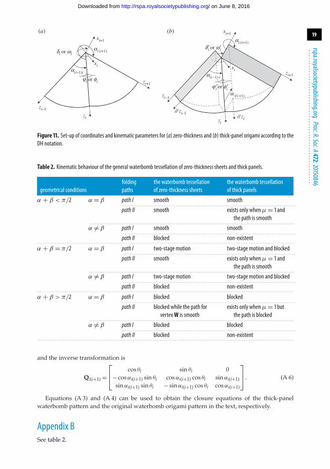
Appendix AAccording to the DH notation set-up in figure 11, the transformation matrix can be assembled as
T(i+1)i =
⎡⎢⎢⎢⎣
cos θi − cos αi(i+1) sin θi sin αi(i+1) sin θi ai(i+1) cos θisin θi cos αi(i+1) cos θi − sin αi(i+1) cos θi ai(i+1) sin θi
0 sin αi(i+1) cos αi(i+1) Ri0 0 0 1
⎤⎥⎥⎥⎦ , (A 1)
which transforms the expression in the i + 1th coordinate system to the ith coordinate system.The inverse transformation can be expressed as
Ti(i+1) =
⎡⎢⎢⎢⎣
cos θi sin θi 0 −ai(i+1)− cos αi(i+1) sin θi cos αi(i+1) cos θi sin αi(i+1) −Ri sin αi(i+1)
sin αi(i+1) sin θi − sin αi(i+1) cos θi cos αi(i+1) −Ri cos αi(i+1)0 0 0 1
⎤⎥⎥⎥⎦ . (A 2)
For a single loop linkage consisting of six links, the closure equation is
T21 · T32 · T43 = T61 · T56 · T45. (A 3)
As for spherical linkages, the axes intersect at one point, which means the lengths of each linksare zeros and thus equation (A 3) reduces to
Q21 · Q32 · Q43 = Q61 · Q56 · Q45, (A 4)
where
Q(i+1)i =
⎡⎢⎣cos θi − cos αi(i+1) sin θi sin αi(i+1) sin θi
sin θi cos αi(i+1) cos θi − sin αi(i+1) cos θi0 sin αi(i+1) cos αi(i+1)
⎤⎥⎦ , (A 5)
on June 8, 2016http://rspa.royalsocietypublishing.org/Downloaded from
19
rspa.royalsocietypublishing.orgProc.R.Soc.A472:20150846
...................................................
xi
xi+1
xi+1
zi–1
zi+1
xizi+1
zi
zi–1
// zi–1// zi
zi
ai (i+1)
ai (i+1)
a(i –1) i
a i(i +1)
a(i–1)i
ji or fi
j ¢i or fi¢
di or wi
d¢i or w¢i
(b)(a)
Figure 11. Set-up of coordinates and kinematic parameters for (a) zero-thickness and (b) thick-panel origami according to theDH notation.
Table 2. Kinematic behaviour of the general waterbomb tessellation of zero-thickness sheets and thick panels.
folding the waterbomb tessellation the waterbomb tessellationgeometrical conditions paths of zero-thickness sheets of thick panels
α + β < π/2 α = β path I smooth smooth. . . . . . . . . . . . . . . . . . . . . . . . . . . . . . . . . . . . . . . . . . . . . . . . . . . . . . . . . . . . . . . . . . . . . . . . . . . . . . . . . . . . . . . . . . . . . . . . . . . . . . . . . . . . . . . . . . . . . . . . . . . . . . . . . . . . . . . . .
path II smooth exists only whenμ = 1 andthe path is smooth
. . . . . . . . . . . . . . . . . . . . . . . . . . . . . . . . . . . . . . . . . . . . . . . . . . . . . . . . . . . . . . . . . . . . . . . . . . . . . . . . . . . . . . . . . . . . . . . . . . . . . . . . . . . . . . . . . . . . . . . . . . . . . . . . . . . . . . . . . . . . . . . . . . . . . . . . . . . . . . . . . .
α �= β path I smooth smooth. . . . . . . . . . . . . . . . . . . . . . . . . . . . . . . . . . . . . . . . . . . . . . . . . . . . . . . . . . . . . . . . . . . . . . . . . . . . . . . . . . . . . . . . . . . . . . . . . . . . . . . . . . . . . . . . . . . . . . . . . . . . . . . . . . . . . . . . .
path II blocked non-existent. . . . . . . . . . . . . . . . . . . . . . . . . . . . . . . . . . . . . . . . . . . . . . . . . . . . . . . . . . . . . . . . . . . . . . . . . . . . . . . . . . . . . . . . . . . . . . . . . . . . . . . . . . . . . . . . . . . . . . . . . . . . . . . . . . . . . . . . . . . . . . . . . . . . . . . . . . . . . . . . . . . . . . . . . . . . . . . . . . . . . . . . . . . . . . . . . . . . . . . . . .
α + β = π/2 α = β path I two-stage motion two-stage motion and blocked. . . . . . . . . . . . . . . . . . . . . . . . . . . . . . . . . . . . . . . . . . . . . . . . . . . . . . . . . . . . . . . . . . . . . . . . . . . . . . . . . . . . . . . . . . . . . . . . . . . . . . . . . . . . . . . . . . . . . . . . . . . . . . . . . . . . . . . . .
path II smooth exists only whenμ = 1 andthe path is smooth
. . . . . . . . . . . . . . . . . . . . . . . . . . . . . . . . . . . . . . . . . . . . . . . . . . . . . . . . . . . . . . . . . . . . . . . . . . . . . . . . . . . . . . . . . . . . . . . . . . . . . . . . . . . . . . . . . . . . . . . . . . . . . . . . . . . . . . . . . . . . . . . . . . . . . . . . . . . . . . . . . .
α �= β path I two-stage motion two-stage motion and blocked. . . . . . . . . . . . . . . . . . . . . . . . . . . . . . . . . . . . . . . . . . . . . . . . . . . . . . . . . . . . . . . . . . . . . . . . . . . . . . . . . . . . . . . . . . . . . . . . . . . . . . . . . . . . . . . . . . . . . . . . . . . . . . . . . . . . . . . . .
path II blocked non-existent. . . . . . . . . . . . . . . . . . . . . . . . . . . . . . . . . . . . . . . . . . . . . . . . . . . . . . . . . . . . . . . . . . . . . . . . . . . . . . . . . . . . . . . . . . . . . . . . . . . . . . . . . . . . . . . . . . . . . . . . . . . . . . . . . . . . . . . . . . . . . . . . . . . . . . . . . . . . . . . . . . . . . . . . . . . . . . . . . . . . . . . . . . . . . . . . . . . . . . . . . .
α + β > π/2 α = β path I blocked blocked. . . . . . . . . . . . . . . . . . . . . . . . . . . . . . . . . . . . . . . . . . . . . . . . . . . . . . . . . . . . . . . . . . . . . . . . . . . . . . . . . . . . . . . . . . . . . . . . . . . . . . . . . . . . . . . . . . . . . . . . . . . . . . . . . . . . . . . . .
path II blocked while the path forvertexW is smooth
exists only whenμ = 1 butthe path is blocked
. . . . . . . . . . . . . . . . . . . . . . . . . . . . . . . . . . . . . . . . . . . . . . . . . . . . . . . . . . . . . . . . . . . . . . . . . . . . . . . . . . . . . . . . . . . . . . . . . . . . . . . . . . . . . . . . . . . . . . . . . . . . . . . . . . . . . . . . . . . . . . . . . . . . . . . . . . . . . . . . . .
α �= β path I blocked blocked. . . . . . . . . . . . . . . . . . . . . . . . . . . . . . . . . . . . . . . . . . . . . . . . . . . . . . . . . . . . . . . . . . . . . . . . . . . . . . . . . . . . . . . . . . . . . . . . . . . . . . . . . . . . . . . . . . . . . . . . . . . . . . . . . . . . . . . . .
path II blocked non-existent. . . . . . . . . . . . . . . . . . . . . . . . . . . . . . . . . . . . . . . . . . . . . . . . . . . . . . . . . . . . . . . . . . . . . . . . . . . . . . . . . . . . . . . . . . . . . . . . . . . . . . . . . . . . . . . . . . . . . . . . . . . . . . . . . . . . . . . . . . . . . . . . . . . . . . . . . . . . . . . . . . . . . . . . . . . . . . . . . . . . . . . . . . . . . . . . . . . . . . . . . .
and the inverse transformation is
Qi(i+1) =
⎡⎢⎣ cos θi sin θi 0
− cos αi(i+1) sin θi cos αi(i+1) cos θi sin αi(i+1)sin αi(i+1) sin θi − sin αi(i+1) cos θi cos αi(i+1)
⎤⎥⎦ . (A 6)
Equations (A 3) and (A 4) can be used to obtain the closure equations of the thick-panelwaterbomb pattern and the original waterbomb origami pattern in the text, respectively.
Appendix BSee table 2.
on June 8, 2016http://rspa.royalsocietypublishing.org/Downloaded from

20
rspa.royalsocietypublishing.orgProc.R.Soc.A472:20150846
...................................................
References1. Hanna BH, Lund JM, Lang RJ, Magleby SP, Howell L. 2014 Waterbomb base: a symmetric
single-vertex bistable origami mechanism. Smart Mater. Struct. 23, 094009. (doi:10.1088/0964-1726/23/9/094009)
2. Bowen L, Springsteen K, Feldstein H, Frecker M, Simpson TW, Lockette PV. 2015Development and validation of a dynamic model of magneto-active elastomer actuation ofthe origami waterbomb base. J. Mech. Robot. 7, 011010. (doi:10.1115/1.4029290)
3. Tachi T, Masubuchi M, Iwamoto M. 2012 Rigid origami structures with vacuumatics:geometric considerations. In Proc. the IASS-APCS Seoul, Korea, 21–24 May.
4. Kuribayashi K, Tsuchiya K, You Z, Tomus D, Umemoto M, Ito T, Sasaki M. 2006 Self-deployable origami stent grafts as a biomedical application of Ni-rich TiNi shape memoryalloy foil. Mater. Sci. Eng. A 419, 131–137. (doi:10.1016/j.msea.2005.12.016)
5. Onal CD, Wood RJ, Rus D. 2013 An origami-inspired approach to worm robots. IEEE/ASMETrans. Mechatron. 18, 430–438. (doi:10.1109/TMECH.2012.2210239)
6. Lee D-Y, Kim J-S, Kim S-R, Koh J-S, Cho K-J. 2013 The deformable wheel robot using magic-ball origami structure. In ASME 2013 Int. Design Engineering Technical Conf . and Computers andInformation in Engineering Conf. IDETC/CIE 2013, Portland, OR, 4–7 August.
7. Chiang CH. 2000 Kinematics of spherical mechanisms. Malabar, FL: Krieger Publication Co.8. Tachi T. 2011 Rigid-foldable thick origami. In Origami5 (ed. AK Peters), pp. 253–264.9. Edmondson BJ et al. 2014 An offset panel technique for thick rigidly foldable origami. In ASME
2014 Int. Design Engineering Technical Conf., Buffalo, NY, 17–21 August 2014.10. Ku JS, Demaine ED. 2015 Folding flat crease patterns with thick materials. J. Mech. Robot. 8,
031003. (doi:10.1115/1.4031954)11. Chen Y, Peng R, You Z. 2015 Origami of thick panels. Science 349, 396. (doi:10.1126/
science.aab2870)12. You Z, Chen Y. 2012 Motion structures. London, UK: Spon Press.13. Bricard R. 1927 Leçons de cinématique. In Tome II Cinématique Appliquée, pp. 7–12. Paris,
France: Gauthier-Villars.14. Beggs JS. 1966 Advanced mechanism. New York, NY: Macmillan Company.15. Phillips J. 1990 Freedom of machinery, volumes II. Cambridge, UK: Cambridge University Press.
on June 8, 2016http://rspa.royalsocietypublishing.org/Downloaded from