symnet express cobra family - home - symetrix · symnet express cobra family introduction •...
TRANSCRIPT
SymNet Express Cobra FamilyQuick Start Guide
Express Cobra 12x4, 8x8, 4x12 and 4x4

6408 216th Street SW | Mountlake Terrace, WA 98043 USA
T +1.425.778.7728 F +1.425.778.7727 | www.SymetrixAudio.com 2
Quick Start GuideSafety

3
SymNet Express Cobra Family Safety
G The lightning flash with arrowhead symbol within an equilateral triangle is intended to alert the user of the presence of uninsulated “dangerous voltage” within the product’s enclosure that may be of sufficient magnitude to constitute a risk of electric shock to persons. The exclamation point within an equilateral triangle is intended to alert the user of the presence of important operating and maintenance (servicing) instructions in the literature accompanying the product (i.e. this Quick Start Guide).
G CAUTION: To prevent electric shock, do not use the polarized plug supplied with the unit with any extension cord, receptacle, or other outlet unless the prongs can be fully inserted.
G Power Source: This Symetrix hardware uses a switching power supply that automatically adjusts to the applied voltage. Ensure that your AC mains voltage is somewhere between 100-240 VAC, 50-60 Hz. Use only the power cord and connector specified for the product and your operating locale. A protective ground connection, by way of the grounding conductor in the power cord, is essential for safe operation. The appliance inlet and coupler shall remain readily operable once the apparatus has been installed.
G User Serviceable Parts: There are no user serviceable parts inside this Symetrix product. In case of failure, customers inside the U.S. should refer all servicing to the Symetrix factory. Customers outside the U.S. should refer all servicing to an authorized Symetrix distributor. Distributor contact information is available online at: http://www.SymetrixAudio.com.
AVIS: NE PAS OUVRIR
Il ne se trouve a l’interieur aucune piece pourvant entre reparée l’usager.
SEE OWNERS MANUAL. VOIR CAHIER D’INSTRUCTIONS.
S’adresser a un reparateur compétent.
RISQUE DE CHOC ELECTRIQUE
No user serviceable parts inside. Refer servicing to qualified service personnel.
CAUTION
WARNING:TO REDUCE THE RISK OF FIRE ORELECTRIC SHOCK DO NOT EXPOSETHIS EQUIPMENT TO RAIN OR MOISTURE
DO NOT OPENRISK OF ELECTRIC SHOCK
Important Safety Instructions! Read these instructions.
@ Keep these instructions.
# Heed all warnings.
$ Follow all instructions.
% Do not use this apparatus near water. This apparatus shall not be exposed to dripping or splashing and no objects filled with liquids, such as vases, shall be placed on the apparatus.
^ Clean only with dry cloth.
& Do not block any ventilation openings. Install only in accordance with the manufacturer’s instructions.
* Do not install near any heat sources such as radiators, heat registers, stoves, or other apparatus (including amplifiers) that produce heat.
( This apparatus shall be connected to a mains socket outlet with a protective earthing connection. Do not defeat the safety purpose of the polarized or grounding-type plug. A polarized plug has two blades with one wider than the other. A grounding type plug has two blades and a third grounding prong. The wide blade or the third prong are provided for your safety. If the provided plug does not fit into your outlet, consult an electrician for replacement of the obsolete outlet.
BL Protect the power cord from being walked on or pinched particularly at plugs, convenience receptacles, and the point where they exit from the apparatus.
BM Only use attachments/accessories specified by the manufacturer.
BN Use only with the cart, stand, tripod, bracket, or table specified by the manufacturer, or sold with the apparatus. When a cart is used, use caution when moving the cart/apparatus combination to avoid injury from tip-over.
BO Unplug this apparatus during lightning storms or when unused for long periods of time.
BP Refer all servicing to qualified service personnel. Servicing is required when the apparatus has been damaged in any way, such as power-supply cord or plug cord is damaged, liquid has been spilled or objects have fallen into the apparatus, the apparatus has been exposed to rain or moisture, does not operate normally, or has been dropped.
What Ships in the Box• AnExpresshardwaredevice.
• SymNetDesignerCD-ROM(Windows).
• Adetachablepowercord.
• ThisQuickStartGuide.
What You Need to Provide• AWindows®PCwith300MHzorhigher
Pentium® and:
• WIN98SE,ME,2000orXP®.
• 10-15MBfreestoragespace.
• 1024x768graphicscapability.
• 16-bitorhighercolors.
• CD-ROMdriveorInternetconnection.
• 64MBRAM(WIN98SE/ME),128MBRAM(WIN2000/XP).
• Anavailableserialportcapableofoperatingat57.6or115.2kilobaud.
• Astraight-throughRS-232cabletoconnect the serial port of your PC to the Express’s rear RS-232 port. The Express’sRS-232inputisafemaleDB-9connector.
• CAT5cablingandEthernetnetworkinghardware as necessary.
Getting HelpSymNet Designer, the Windows application that controls all SymNet hardware, includes a help module which acts as a complete User’s Guide for both hardware (including the Express Cobra device) and software.
If you have questions beyond the scope of the help module, contact our Customer Support Group in the following ways:
Tel: +1.425.778.7728
8:00 am to 4:30 pm
Monday through Friday,
Pacific Time
Web: http://www.SymetrixAudio.com
This device complies with part 15 of the FCC Rules. Operation is subject to the following two conditions: (1) This device may not cause harmful interference, and (2) this device must accept any interference received, including interference that may cause undesired operation.
ThisClassBDigitalapparatusmeetsallrequirements of the Canadian Interference-Causing Equipment Regulations
Cet appariel numerique de la classe BrespectetouteslesExigencesduReglement sur le materiel brouilleur du Canada.
Keep up-to-date with the latest version of SymNet Designer™, the Windows® application that controls all SymNet hardware, go to: http://www.SymetrixAudio.com
6408 216th Street SW | Mountlake Terrace, WA 98043 USA
T +1.425.778.7728 F +1.425.778.7727 | www.SymetrixAudio.com 4
Quick Start GuideWarning
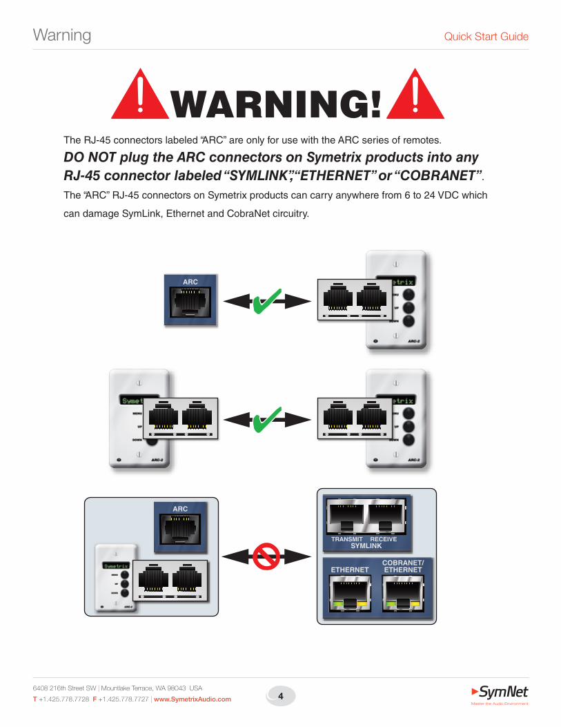
The RJ-45 connectors labeled “ARC” are only for use with the ARC series of remotes.
DO NOT plug the ARC connectors on Symetrix products into any RJ-45 connector labeled “SYMLINK”, “ETHERNET” or “COBRANET”.
The “ARC” RJ-45 connectors on Symetrix products can carry anywhere from 6 to 24 VDC which
can damage SymLink, Ethernet and CobraNet circuitry.
ARC
ARC
SYMLINKTRANSMIT RECEIVE
COBRANET/ETHERNETETHERNET
5
SymNet Express Cobra Family Introduction•Overview
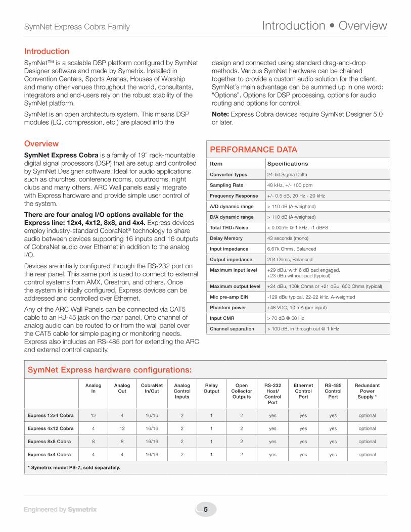
SymNet Express hardware configurations:
Analog In
Analog Out
CobraNet In/Out
Analog Control Inputs
Relay Output
Open Collector Outputs
RS-232 Host/
Control Port
Ethernet Control
Port
RS-485 Control
Port
Redundant Power
Supply *
Express 12x4 Cobra 12 4 16/16 2 1 2 yes yes yes optional
Express 4x12 Cobra 4 12 16/16 2 1 2 yes yes yes optional
Express 8x8 Cobra 8 8 16/16 2 1 2 yes yes yes optional
Express 4x4 Cobra 4 4 16/16 2 1 2 yes yes yes optional
* Symetrix model PS-7, sold separately.
IntroductionSymNet™ is a scalable DSP platform configured by SymNet Designer software and made by Symetrix. Installed in Convention Centers, Sports Arenas, Houses of Worship and many other venues throughout the world, consultants, integrators and end-users rely on the robust stability of the SymNet platform.
SymNet is an open architecture system. This means DSP modules (EQ, compression, etc.) are placed into the
design and connected using standard drag-and-drop methods. Various SymNet hardware can be chained together to provide a custom audio solution for the client. SymNet’s main advantage can be summed up in one word: “Options”. Options for DSP processing, options for audio routing and options for control.
Note: Express Cobra devices require SymNet Designer 5.0 or later.
OverviewSymNet Express Cobraisafamilyof19”rack-mountabledigital signal processors (DSP) that are setup and controlled by SymNet Designer software. Ideal for audio applications such as churches, conference rooms, courtrooms, night clubs and many others. ARC Wall panels easily integrate with Express hardware and provide simple user control of the system.
There are four analog I/O options available for the Express line: 12x4, 4x12, 8x8, and 4x4. Express devices employ industry-standard CobraNet® technology to share audio between devices supporting 16 inputs and 16 outputs of CobraNet audio over Ethernet in addition to the analog I/O.
Devices are initially configured through the RS-232 port on the rear panel. This same port is used to connect to external controlsystemsfromAMX,Crestron,andothers.Oncethe system is initially configured, Express devices can be addressed and controlled over Ethernet.
Any of the ARC Wall Panels can be connected via CAT5 cable to an RJ-45 jack on the rear panel. One channel of analog audio can be routed to or from the wall panel over the CAT5 cable for simple paging or monitoring needs. ExpressalsoincludesanRS-485portforextendingtheARCand external control capacity.
PERFORMANCE DATA
Item Specifications
Converter Types 24-bit Sigma Delta
Sampling Rate 48kHz,+/-100ppm
Frequency Response +/-0.5dB,20Hz-20kHz
A/D dynamic range >110dB(A-weighted)
D/A dynamic range >110dB(A-weighted)
Total THD+Noise <0.005%@1kHz,-1dBFS
Delay Memory 43 seconds (mono)
Input impedance 6.67kOhms,Balanced
Output impedance 204Ohms,Balanced
Maximum input level +29dBu,with6dBpadengaged, +23dBuwithoutpad(typical)
Maximum output level +24dBu,100kOhmsor+21dBu,600Ohms(typical)
Mic pre-amp EIN -129dButypical,22-22kHz,A-weighted
Phantom power +48VDC,10mA(perinput)
Input CMR >70dB@60Hz
Channel separation >100dB,inthroughout@1kHz

6408 216th Street SW | Mountlake Terrace, WA 98043 USA
T +1.425.778.7728 F +1.425.778.7727 | www.SymetrixAudio.com 6
Quick Start GuideMechData•Front/RearPanel
Mechanical Data
Item Specifications Remarks
SPACE REQUIRED 1U(WDH:48.3cmx27.4cmx4.37cm/19inx10.8inx1.72in).Depthdoesnotincludeconnector allowance.
Allow at least 1 inch additional clearance for rear panel connections. Additional depth may be required depending upon your specific wiring and connections.
ELECTRICAL 100 to 240 VAC, 50-60 Hz, 60 watts maximum. No line voltage switching required.
VENTILATION Maximumrecommendedambientoperatingtemperatureis30C/86F.
Fan on equipment right pulls hot air out of unit. Air intake at equipment left. Ensure that theleftandrightequipmentsidesareunobstructed(5.08cm,2inminimumclearance).The ventilation should not be impeded by covering the ventilation openings with items such as newspapers, tablecloths, curtains, etc.
WEIGHT 6 kg (12 lbs.)
Front Panel
Item Description Remarks
POWER Red LED Indicates that the device is powered on.
LEDislitsolidwhenoperatingfromtheMAINPOWER.
LEDisflashingwhenoperatingfromtheAUXPOWER.
Note:TheLEDwillflashthenumberoftimesequivalenttoitsRINGNUMBERuponpowerup.
COMM Yellow LED Indicates current host communications.
COBRANET Green LED Indicates a valid CobraNet connection.
SIGNAL LEVEL Bi-colorLEDs Indicates input or output signal level with four levels of intensity (OFF,-48dBFS,-24dBFS,-12dBFS)andsignalclipping(0dBFS). •InputlevelisindicatedinORANGE. •OutputlevelisindicatedinGREEN.•ClippingisindicatedinRED.
Rear Panel
Item Description Remarks
POWER INPUT IEC 3 prong jack Accepts power from detachable IEC power cable (100-240 VAC, 50-60 Hz, 25 Watts max).
AUX POWER MaleXLR-4jack AcceptspowerfromSymetrixmodelPS-7oruser-suppliedauxiliarypowerconnection(24VDC,2.5Amps, 60 Watts max).
NOTE: Detachable Euroblock connectors are designed for use with bare wire. Do not tin stranded wires before inserting them into the connectors.

7
SymNet Express Cobra Family RearPanel•HostConnections
Rear Panel Continued
Item Description Remarks
ARC AUDIO 3 pin Euroblock Splits a single analog line level audio signal off of the ARC port. Can be wired to a line level analog input or output jack for remote audio over CAT5.
ARC RJ-45 DistributespowerandRS-485datatooneormoreARCsperport.(See:ARCNetworkDesign).
RS-485 3 pin Euroblock ConnectstoaControlI/O,ARC-PS,ARCorotherSymetrixSymNetfamilyRS-485controller,wiredinparallel(AtoA,BtoBandGNDtoGND)usingshieldedtwistedpair.PortSettings:38.4kbaud(default),8databits,1stopbit,no parity, no flow control.
RS-232 FemaleDB9 SerialcommunicationsinterfaceforSymNetDesigneronthehostPCora3rdpartyaccessorycontroller.(Modeisdeterminedbythe“RS-232:Host/Acc”modeswitch.)PortSettings(Host):115or57.6kbaud,8databits,1stopbit,noparity,noflowcontrolPortSettings(Acc):38.4kbaud(default),8databits,1stopbit,noparity,noflowcontrol.
DEVICE CONFIG 8DIPswitchblock Configures the Express’s RS-232 port mode, RS-232 port host mode baud rate and Ring Number (device address).
ETHERNET RJ-45 10/100Base-TEthernetportforSymNetDesignerhostcontroloverIP.IPcontrolmustbesetupfromSymNetDesigner via RS-232 first for security.
COBRANET/ETH-ERNET
RJ-45 10/100Base-TEthernetportforCobraNetaudio.(FuturesoftwareversionsmaysupportSymNetDesignerhostcontroloverIP+CobraNetonthissameport.)
RELAY OUT 3 pin Euroblock 1 SPDT relay rated at 3 Amps, 24 VDC, resistive; 0.3 Amps, 60 VDC, resistive and can be wired normally open or normally closed. This relay can also be used for power failure detection or emergency alarm system integration.
O/C (open collector) OUT
3 pin Euroblock 2 open collector outputs with a paired common ground pin. O/C outputs go low (0V) when active, and are internally pulled high (5V) when inactive and can drive external LED indicators directly.
CONTROL IN 3 pin Euroblocks 2 analog control inputs able to be used as 2 potentiometer inputs, 2 mechanical rotary encoder inputs, or as 4 switchinputs(+5VDCreferencevoltagesupplied).
ANALOG OUTPUTS 3 pin Euroblocks 4,8or12analoglinelevelaudioinputswithindividuallysoftware-selectablelevelof-10dBVor+4dBu.
ANALOG INPUTS 3 pin Euroblocks 4,8or12analogmic/linelevelaudioinputswithindividuallysoftware-selectablephantompowerandlevelof-50dBu,-40dBu,-20dBu,-10dBVor+4dBu.
Host CommunicationsThe host PC (running SymNet Designer) can communicate directly with the Express as a stand alone device (Ring #1) in one of two ways: RS-232 or Ethernet. Control over CobraNet may be available in a future software release. For the time being, the CobraNet port is for CobraNet Network Audio only and the Ethernet port is for host control only.
RS-232:The Express has only one RS-232 port on the rear of the device, a slight departure from the traditional SymNet DSP devices. As a result, this rear panel RS-232 port sees double duty as both a host PC interface or a 3rd party RS-232 accessory controller interface, but not both simultaneously. The port’s purpose is set by DIP switch #2 labeled “RS-232: Host / Acc”. When this switch is set to the “Host” position, DIPswitch#1labeled“HOST:115k/57k”determinesthebaudrateoftheRS-232port(115.2or57.6kilobaud)andthisbaudratemustmatch the baud rate chosen in SymNet Designer’s Preferences dialog. When DIP switch #2 is set to the “Acc” position, the RS-232 port’s baudratedefaultsto38.4kunlesschangedbytheRS-232ControlProtocol or SymNet Designer’s Upgrade Firmware dialog.
Ethernet:TheExpress’s10/100Base-TEthernetportisavailableforuseregardless of DIP switch #2’s position. Ethernet or “IP” control is the only way that multiple Express devices can be configured within the same Site File. With an Express Cobra’s Ethernet and CobraNet ports, these devices can be made part of a larger SymNet system which may utilize1ormoreRingsoftraditionalSymNethardware(CobraLink,8x8DSP,BreakIn12,andBreakOut12).
Note: Ethernet communications settings (IP addresses and access codes) must first be set up from SymNet Designer via the RS-232 port interface. Please see the SymNet Designer online help for further information.
6408 216th Street SW | Mountlake Terrace, WA 98043 USA
T +1.425.778.7728 F +1.425.778.7727 | www.SymetrixAudio.com 8
Quick Start GuideMulti-RingSystems•DeviceAddresing•RelayOut
Multi-Ring SystemsWhen using multiple Express devices or integrating Express and traditional SymNet Rings, there are basically two ways in which to set up multi-ring systems. The decision to make is whether you would like to manage the rings as a whole system from the same Site File or manage the rings as completely independent systems (unique Site Files).
Interfacing to manage each ring as a separate system can be done via RS-232 or Ethernet. If by Ethernet, care must be taken to avoid IP conflicts and accessibility should be considered - general network design and administration issues. If by RS-232, separate PCs can be permanently connected to each ring individually, or one PC could be meant to ‘roam’ amongst them.
To manage the rings in one Site File as a whole system, each hardware device must have its own dedicated Ethernet connection to a common hub, switch, router or existing network. Any properly set up PC on the network can then control the system.
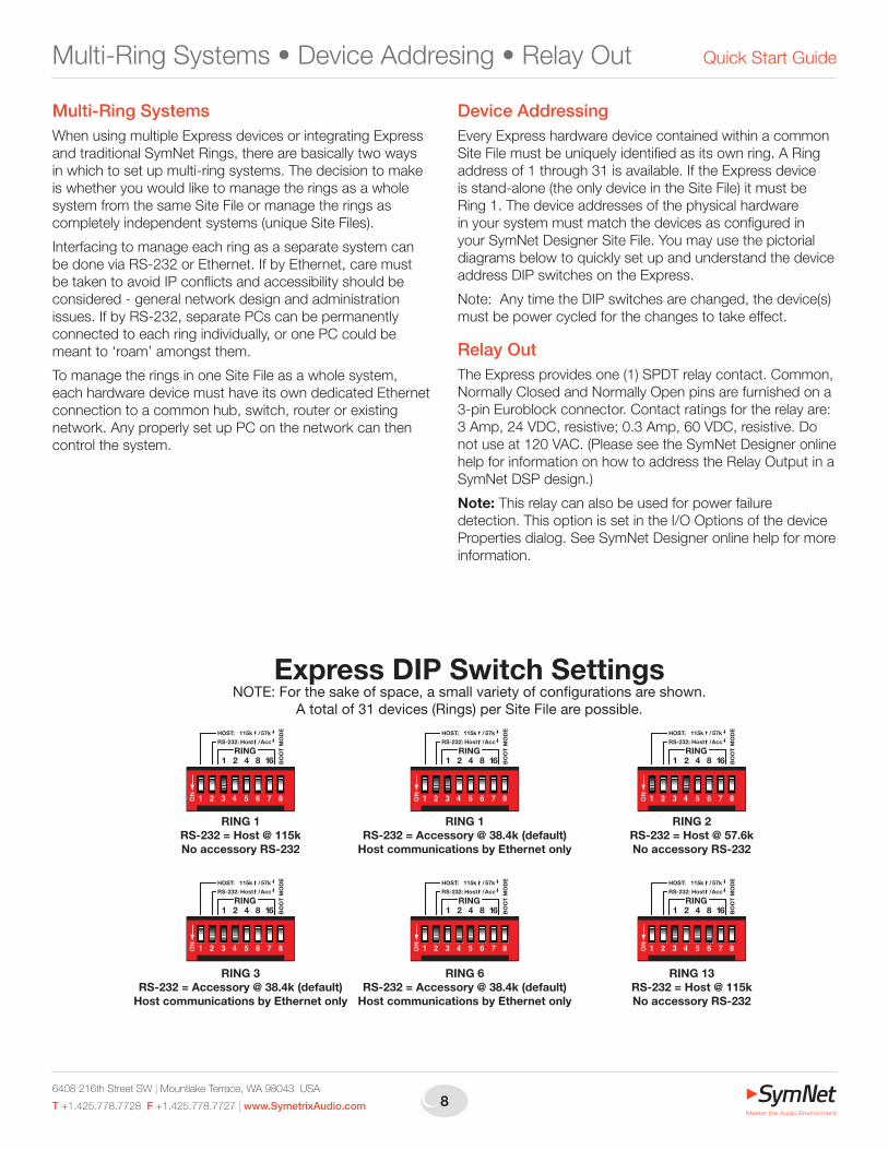
Device AddressingEvery Express hardware device contained within a common Site File must be uniquely identified as its own ring. A Ring address of 1 through 31 is available. If the Express device is stand-alone (the only device in the Site File) it must be Ring 1. The device addresses of the physical hardware in your system must match the devices as configured in your SymNet Designer Site File. You may use the pictorial diagrams below to quickly set up and understand the device address DIP switches on the Express.
Note: Any time the DIP switches are changed, the device(s) must be power cycled for the changes to take effect.
Relay OutThe Express provides one (1) SPDT relay contact. Common, Normally Closed and Normally Open pins are furnished on a 3-pin Euroblock connector. Contact ratings for the relay are: 3 Amp, 24 VDC, resistive; 0.3 Amp, 60 VDC, resistive. Do not use at 120 VAC. (Please see the SymNet Designer online help for information on how to address the Relay Output in a SymNet DSP design.)
Note: This relay can also be used for power failure detection. This option is set in the I/O Options of the device Properties dialog. See SymNet Designer online help for more information.
Express DIP Switch SettingsNOTE: For the sake of space, a small variety of con�gurations are shown.
A total of 31 devices (Rings) per Site File are possible.
RING 13RS-232 = Host @ 115kNo accessory RS-232
RING 6RS-232 = Accessory @ 38.4k (default)
Host communications by Ethernet only
RING 3RS-232 = Accessory @ 38.4k (default)
Host communications by Ethernet only
RING 2RS-232 = Host @ 57.6kNo accessory RS-232
RING 1RS-232 = Accessory @ 38.4k (default)
Host communications by Ethernet only
RING 1RS-232 = Host @ 115kNo accessory RS-232
HOST:
RS-232:
115k 57k/
BO
OT
MO
DE
RING1 2 4 8 16
Host Acc/
HOST:
RS-232:
115k 57k/
BO
OT
MO
DE
RING1 2 4 8 16
Host Acc/
HOST:
RS-232:
115k 57k/B
OO
T M
OD
E
RING1 2 4 8 16
Host Acc/
HOST:
RS-232:
115k 57k/
BO
OT
MO
DE
RING1 2 4 8 16
Host Acc/
HOST:
RS-232:
115k 57k/
BO
OT
MO
DE
RING1 2 4 8 16
Host Acc/
HOST:
RS-232:
115k 57k/
BO
OT
MO
DE
RING1 2 4 8 16
Host Acc/
9
SymNet Express Cobra Family BinaryOutputs•AnalogControlInputs
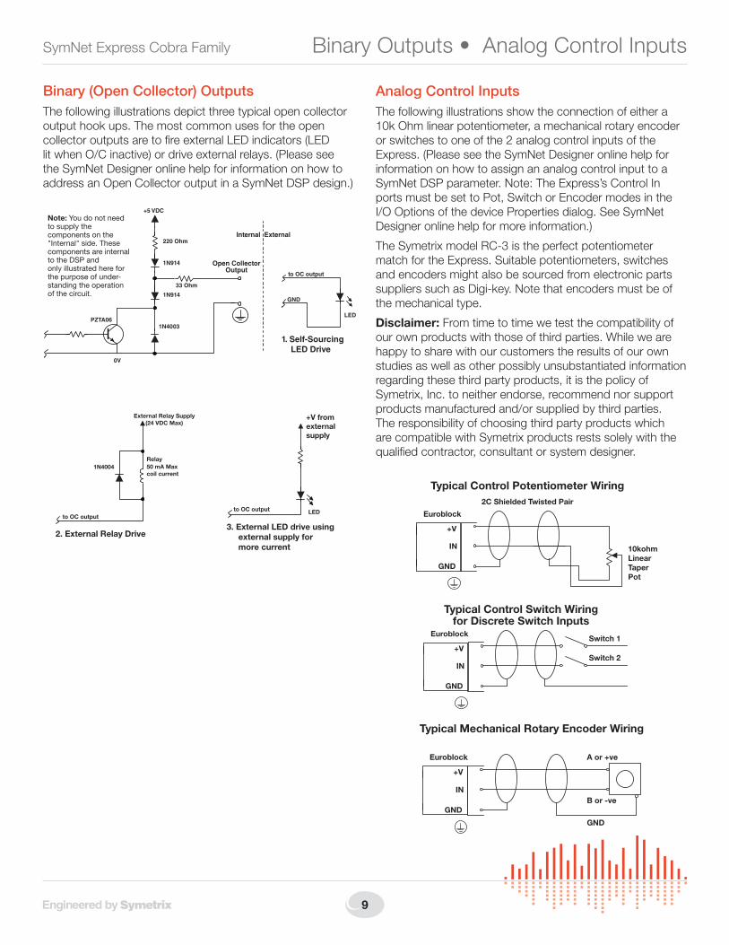
Binary (Open Collector) OutputsThe following illustrations depict three typical open collector output hook ups. The most common uses for the open collector outputs are to fire external LED indicators (LED lit when O/C inactive) or drive external relays. (Please see the SymNet Designer online help for information on how to address an Open Collector output in a SymNet DSP design.)
Analog Control InputsThe following illustrations show the connection of either a 10k Ohm linear potentiometer, a mechanical rotary encoder or switches to one of the 2 analog control inputs of the Express. (Please see the SymNet Designer online help for information on how to assign an analog control input to a SymNet DSP parameter. Note: The Express’s Control In ports must be set to Pot, Switch or Encoder modes in the I/O Options of the device Properties dialog. See SymNet Designer online help for more information.)
The Symetrix model RC-3 is the perfect potentiometer match for the Express. Suitable potentiometers, switches and encoders might also be sourced from electronic parts suppliers such as Digi-key. Note that encoders must be of the mechanical type.
Disclaimer: From time to time we test the compatibility of our own products with those of third parties. While we are happy to share with our customers the results of our own studies as well as other possibly unsubstantiated information regarding these third party products, it is the policy of Symetrix, Inc. to neither endorse, recommend nor support products manufactured and/or supplied by third parties. The responsibility of choosing third party products which are compatible with Symetrix products rests solely with the qualified contractor, consultant or system designer.
1. Self-Sourcing LED Drive
Internal External
Note: You do not needto supply thecomponents on the"Internal" side. Thesecomponents are internalto the DSP andonly illustrated here forthe purpose of under-standing the operationof the circuit.
Open CollectorOutput
to OC output
LED
GND
+5 VDC
0V
220 Ohm
33 Ohm
PZTA061N4003
1N914
1N914
2. External Relay Drive
to OC output
Relay
External Relay Supply(24 VDC Max)
50 mA Maxcoil current
1N4004
+V fromexternalsupply
3. External LED drive using external supply for more current
to OC output LED Euroblock
2C Shielded Twisted Pair
10kohmLinearTaperPot
+V
IN
GND
Typical Control Potentiometer Wiring
EuroblockSwitch 1
+V
IN
GND
Typical Control Switch Wiringfor Discrete Switch Inputs
Switch 2
Euroblock A or +ve
B or -ve
GND
+V
IN
GND
Typical Mechanical Rotary Encoder Wiring
6408 216th Street SW | Mountlake Terrace, WA 98043 USA
T +1.425.778.7728 F +1.425.778.7727 | www.SymetrixAudio.com 10
Quick Start Guide
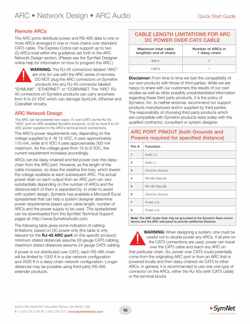
Remote ARCsTheARCportsdistributepowerandRS-485datatooneormore ARCs arranged in one or more chains over standard CAT5 cable. The Express Cobra can support up to two (2) ARCs total within the guidelines set forth in the ARC Network Design section. (Please see the SymNet Designer online help for information on how to program the ARC.)
WARNING: The RJ-45 connectors labeled “ARC” are only for use with the ARC series of remotes.
DO NOT plug the ARC connectors on Symetrix products into any RJ-45 connector labeled
“SYMLINK”,“ETHERNET”or“COBRANET.The“ARC”RJ-45 connectors on Symetrix products can carry anywhere from 6 to 24 VDC which can damage SymLink, Ethernet and CobraNet circuitry.
ARC Network DesignThe ARC can be powered two ways: (1) over CAT5 via the RJ-45 “ARC” port on ARC-enabled Symetrix products, or (2) by local 6 to 24 VDC power supplied to the ARC’s terminal block connections.
The ARC’s power requirements vary depending on the voltage supplied to it. At 15 VDC, it uses approximately 115 mA, while at 6 VDC it uses approximately 300 mA maximum. As the voltage goes from 15 to 6 VDC, the current requirement increases accordingly.
ARCs can be daisy-chained and fed power over this daisy-chain from the ARC port. However, as the length of the cable increases, so does the resistive line loss, which lowers the voltage available at each subsequent ARC. The actual power drain on each output from an ARC port can vary substantially depending on the number of ARCs and the distance each of them is separated by. In order to assist withsystemdesign,SymetrixhasavailableaMicrosoftExcelspreadsheet that can help a system designer determine power requirements based upon cable length, number of ARCs and the power supply to be used. This spreadsheet can be downloaded from the SymNet Technical Support pages at: http://www.SymetrixAudio.com.
The following table gives some indication of cabling limitations, based on DC power only (the table is only relevant for the RJ-45 ARC port on this specific product): minimumstateddistancesassume28gaugeCAT5cabling,maximum stated distances assume 24 gauge CAT5 cabling.
IfpowerisnotdistributedoverCAT5,eachRS-485chainwill be limited to 1000 ft in a star network configuration and 4000 ft in a daisy-chain network configuration. Longer distancesmaybepossibleusingthirdpartyRS-485extender products.
Disclaimer: From time to time we test the compatibility of our own products with those of third parties. While we are happy to share with our customers the results of our own studies as well as other possibly unsubstantiated information regarding these third party products, it is the policy of Symetrix, Inc. to neither endorse, recommend nor support products manufactured and/or supplied by third parties. The responsibility of choosing third party products which are compatible with Symetrix products rests solely with the qualified contractor, consultant or system designer.
WARNING: When designing a system, one must be careful not to double power any ARCs. If all pins on
the CAT5 connections are used, power can travel over the CAT5 cable and reach any ARC on
that particular chain. So, power over CAT5 could potentially come from the originating ARC port or from an ARC that is powered locally and then daisy chained via CAT5 to other ARCs. In general, it is recommended to use only one type of connector on the ARCs, either the RJ-45s (with CAT5 cable) or the terminal blocks
ARC•NetworkDesign•ARCAudio
ARC PORT PINOUT (both Grounds and Powers required for specified distance)
Pin # Function
1 Audio(+)
2 Audio (-)
3 Common Ground
4 RS-485Data(A)
5 RS-485Data(B)
6 Common Ground
7 Power(+V)
8 Power(+V)
Note: The ARC Audio lines may be grounded at the Symetrix Rack-mount device and the ARC wall panel to provide additional distance.
CABLE LENGTH LIMITATIONS FOR ARC DC POWER OVER CAT5 CABLE
Maximum total cable length(to end of chain)
Number of ARCs in 1 daisy-chain
699ft. 2
1396ft. 1

11
SymNet Express Cobra Family
ARC AudioARC Audio provides a means to take a single balanced analog audio line and either inject it into or pick it off an RS-485network’sCAT5cablerun.AnARCAudioportonaSymetrix device may be wired to a nearby device’s analog input or output. This provides a means of easily running a single audio channel to or from a remote source or destination. TheARC-MICandARC-XLRmakeuseofARCAudiototransport audio signals back to a SymNet rack mount unit.
Note 1:TheoriginalMenuARCremote(simplynamed“ARC”) does not support ARC Audio lines and will ground the audio lines if connected.
Note 2: To avoid the possible grounding, mixing, or shorting of the ARC Audio lines, it is recommended to home run any ARC devices making use of the ARC Audio lines so that only one ARC device is on each chain.
Limits of ARC AudioARC Audio is a simple analog audio signal travelling the samecableastheRS-485dataandpower.Assuch,theusual audio signal cautions apply. Avoid running parallel to otherpowerlinesornearanyothersourcesofEMIorRFI.MostCAT5isunshieldedandissusceptibletointerferenceand noise. We provide here the following information on ARC Audio’s performance and limitations:
Line-level Balanced Audio:Professional line level balanced signals can also be sent over up to approximately 1500 feet of CAT5 without significant degradation.
All unbalanced signals should be avoided completely.
Mic-level Audio:Unbuffered condenser or dynamic microphones should generally be avoided, though it may be possible to achieve decent quality with cable runs of less than 50 feet using a fairly hot microphone level with a noise gate or expander in to clean up the signal. This technique does not provide much flexibility within the system design, and therefore is not recommended.
Frequency response:Frequency response can roll-off due to the capacitance of a long cable run. The amount of roll-off is highly dependent on source impedance (the output impedance of what is supplyingthesignal).Mostproaudiodeviceshavelowoutput impedances (200 Ohms or less) and do not suffer significantroll-off(approximately-1dBat20kHzwith1500feet of CAT5). A device with a 600 Ohm output impedance couldcausesomeaudibleroll-off(-3dBat10kHz),butshould be of sufficient quality for speech signals.
Data Noise:With an unbuffered mic and long cables, data noise may be audible as a “motorboat” sound. Experimenting with RS-485terminationandbaudratemayimprovethesoundsomewhat.
RS-485 TerminationBoththeARCandtheExpressfeatureanRS-485terminationjumper.JumperJ28insidetheExpressbytheRS-485jackenablesanddisablestermination.Jumpingthe pins = terminated, open = unterminated. For maximum signal integrity, follow the termination guidelines below:
Aux PowerThe4-pinXLRAuxPowerconnectorprovidesameansof easily adding an optional redundant power supply, the SymetrixmodelnumberPS-7,toExpress.ThisprovidesExpress a cost-effective and easy upgrade path to a certain level of fault tolerance. Should main power be lost or the main power supply fail for any reason, the Express will automatically switch over to the Aux Power input, glitch-free, if present. When operating on the Aux Power input, the POWER LED on the front of the Express will flash. When main power is restored, the Express will automatically switch back over to the main supply and the POWER LED will once again light solid.
The Aux Power input can also be wired into a user-supplied 24VDC,2.5Amp,60Wattbackuppowersource.TheXLR-4 pinout follows:
RS-485Termination•AuxPower
AUX POWER
+24VDC2.5A
1
23
4
AUX POWER XLR-4 PINOUT
Pin # Function
1 Ground
2 Unused
3 Unused
4 Power(+V)
RS-485 TERMINATION GUIDELINES
Daisy-chain length Termination
0 - 200 ft. No termination required
200 - 1000 ft. (if powering over CAT5)
Terminate at the ARC
> 1000 ft. (or if not powering over CAT5)
Terminate at the ARC-PS, Control I/O or DSP device and at the furthest
ARC device
6408 216th Street SW | Mountlake Terrace, WA 98043 USA
T +1.425.778.7728 F +1.425.778.7727 | www.SymetrixAudio.com 12
Quick Start GuideCobraNet
ExpressCobra
SWITCH
PC
SWITCH CobraLink
8x8 DSP
BreakIn12
BreakOut12
ExpressCobra
Receive
Transmit
Receive
Transmit
Receive
Transmit
Receive
Transmit
SymLink
RS-232
Ethernet
CobraNet
Legend:
CobraLink ExpressCobra
PC
SWITCH
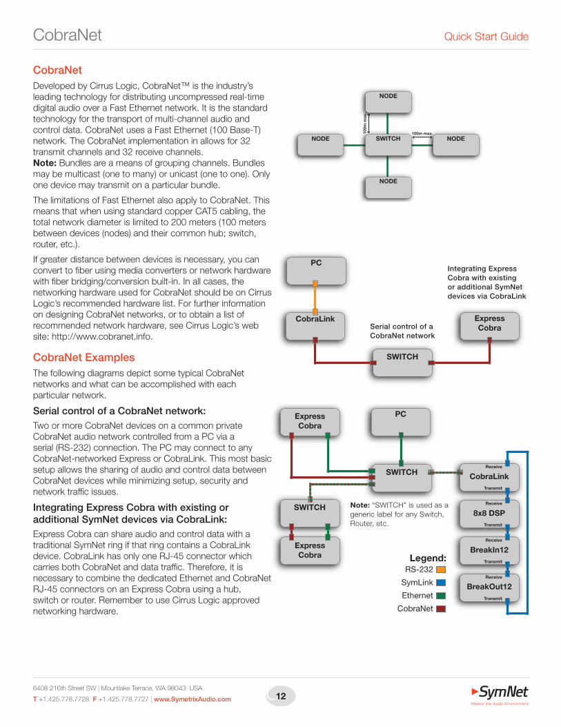
CobraNetDeveloped by Cirrus Logic, CobraNet™ is the industry’s leading technology for distributing uncompressed real-time digital audio over a Fast Ethernet network. It is the standard technology for the transport of multi-channel audio and controldata.CobraNetusesaFastEthernet(100Base-T)network. The CobraNet implementation in allows for 32 transmit channels and 32 receive channels. Note:Bundlesareameansofgroupingchannels.Bundlesmay be multicast (one to many) or unicast (one to one). Only one device may transmit on a particular bundle.
The limitations of Fast Ethernet also apply to CobraNet. This means that when using standard copper CAT5 cabling, the total network diameter is limited to 200 meters (100 meters between devices (nodes) and their common hub; switch, router, etc.).
If greater distance between devices is necessary, you can convert to fiber using media converters or network hardware with fiber bridging/conversion built-in. In all cases, the networking hardware used for CobraNet should be on Cirrus Logic’s recommended hardware list. For further information on designing CobraNet networks, or to obtain a list of recommended network hardware, see Cirrus Logic’s web site: http://www.cobranet.info.
CobraNet ExamplesThe following diagrams depict some typical CobraNet networks and what can be accomplished with each particular network.
Serial control of a CobraNet network:Two or more CobraNet devices on a common private CobraNet audio network controlled from a PC via a serial (RS-232) connection. The PC may connect to any CobraNet-networked Express or CobraLink. This most basic setup allows the sharing of audio and control data between CobraNet devices while minimizing setup, security and network traffic issues.
Integrating Express Cobra with existing or additional SymNet devices via CobraLink:Express Cobra can share audio and control data with a traditional SymNet ring if that ring contains a CobraLink device. CobraLink has only one RJ-45 connector which carries both CobraNet and data traffic. Therefore, it is necessary to combine the dedicated Ethernet and CobraNet RJ-45 connectors on an Express Cobra using a hub, switch or router. Remember to use Cirrus Logic approved networking hardware.
Note: “SWITCH” is used as a generic label for any Switch, Router, etc.
Serial control of a CobraNet network
Integrating Express Cobra with existing or additional SymNet devices via CobraLink
SWITCH NODENODE
NODE
NODE
100m
max
.
100m max.
13
SymNet Express Cobra Family SymNet Designer Software
SymNet Designer SoftwareInstallationThe SymNet Designer software provides real-time control overmultipleaudiofunctionsfromaWindows98/2000/XPPC environment.
Use one of the following procedures to install the SymNet Designer on your computer.
FromtheSymNetDesignerCD-ROM:
1. InserttheCD-ROMintoyourcomputer’sCD-ROMdrive.
2. If the software does not auto run, Click on the Start button, Run D:\SETUP
(IfyourCD-ROMdriveisn’tD:,thensubstituteitsdriveletter)
From the Symetrix web site (http://www.SymetrixAudio.com):
1. Download the SymNet Designer self-extracting installer.
2. Find the file you downloaded and double-click it to start the Setup program.
The software always starts up in offline mode. Regard-less, you can explore the software, experiment to your heart’s content, and perhaps even get useful work done. You can save any Sites that you create to a file that can be downloaded later into an operating SymNet system.
If there is a SymNet hardware device connected, you can download to, and upload from the SymNet system. Once you have a device connected, you can also work online in real time, which allows you to hear adjust ments and settings as you make them.
Using SymNet DesignerOnce the installation process is complete, you should have an icon on your desktop, and a program item in the Start menu. Click on the SymNet Designer icon and you’re ready to begin.
SymNet Designer is mostly self-explanatory. The Con-figuration Screen represents all SymNet hardware devices in a sys tem. Each device can store up to 1000 presets. Using the tool kit (left-hand) window, you select the SymNet device that you wish to configure and drag it to the configuration page. Double-clicking on the device opens it, and causes the tool kit to display all the different signal processors available. The tool kit window is context sensitive. It always displays the items that can be placed in the current window. YoucanusetheBrowsertonavigatetoalloftherelevantwindows opened.
Drag and drop signal processors into the configuration page. Connect them together by clicking on a connec tion point and moving the mouse in the direction you want the wire torun.Makecornersbyclickingatthecornerandmovingoff in a new direction. Terminate a wire by clicking on the terminating connection point or by hit ting the ESC key or right mouse button. Right click on an existing wire and choose “Start Wire” to make a tee connection.
Once you’ve completed your design, download it to the SymNet system. Double click on pro cessors on the configuration page to see their DSP modules and routing. Double-click on a DSP module to change its settings.
Note:Manyusefulfunctionsareavailableinthemouse right-click. Explore! That’s the ultra-condensed version. You’ll find more complete information in SymNet Designer’s online help.
Hardware MemorySymNet saves its settings in internal flash memory, allowing it to recall settings through a power-down/up cycle. Unlike staticRAM,theflashmemorydoesnotrequirebatteries,andis designed to retain its memory for the life of the product.
6408 216th Street SW | Mountlake Terrace, WA 98043 USA
T +1.425.778.7728 F +1.425.778.7727 | www.SymetrixAudio.com 14
Quick Start GuideWiring Reference
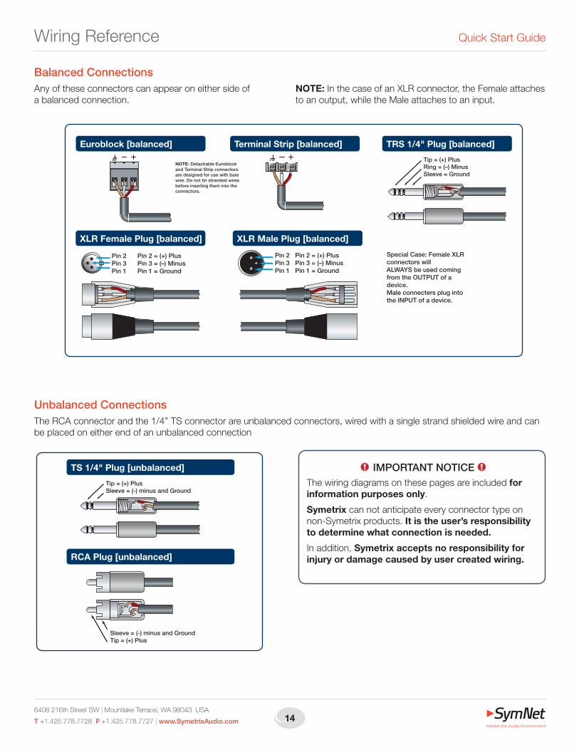
XLR Male Plug [balanced]
Pin 2Pin 3Pin 1
Pin 2 = (+) PlusPin 3 = (–) MinusPin 1 = Ground
XLR Female Plug [balanced]
Pin 2 = (+) PlusPin 3 = (–) MinusPin 1 = Ground
Pin 2Pin 3Pin 1
Terminal Strip [balanced] TRS 1/4" Plug [balanced]
Tip = (+) PlusRing = (–) MinusSleeve = Ground
Euroblock [balanced]
NOTE: Detachable Euroblock and Terminal Strip connectors are designed for use with bare wire. Do not tin stranded wires before inserting them into the connectors.
Special Case: Female XLR connectors willALWAYS be used coming from the OUTPUT of a device.Male connecters plug into the INPUT of a device.
Balanced ConnectionsAny of these connectors can appear on either side of a balanced connection.
NOTE:InthecaseofanXLRconnector,theFemaleattachestoanoutput,whiletheMaleattachestoaninput.
Unbalanced ConnectionsThe RCA connector and the 1/4” TS connector are unbalanced connectors, wired with a single strand shielded wire and can be placed on either end of an unbalanced connection
TS 1/4" Plug [unbalanced]
Tip = (+) PlusSleeve = (-) minus and Ground
RCA Plug [unbalanced]
Sleeve = (-) minus and GroundTip = (+) Plus
1! IMPORTANT NOTICE 1!
The wiring diagrams on these pages are included for information purposes only.
Symetrix can not anticipate every connector type on non-Symetrix products. It is the user’s responsibility to determine what connection is needed.
In addition, Symetrix accepts no responsibility for injury or damage caused by user created wiring.

15
SymNet Express Cobra Family Wiring Reference
Unbalanced Connections:Unbalanced out to balanced inThe RCA connector and the 1/4” TS connector are unbalanced connectors. However, the wiring differs depending on if they are sending to, or receiving from a balanced connector.
In this example, the unbalanced connector is sending signal to a balanced connector. When wiring this connection, use a shielded twisted pair cable. The balanced side wires the same as a standard, balanced connection. On the unbalanced side, you wire the white (minus) wire together with the ground. This provides some common mode rejection at the balanced input.
Unbalanced Connections:Balanced out to unbalanced inWhen your output requires a balanced connector, but you
are sending signal to an unbalanced input, the rules change. Use a single strand shielded wire. Wire only to the plus and ground terminals of what would the typically be the balanced connector.
XLR Male Plug [balanced]
TS 1/4" Plug [unbalanced out to balanced in]
TRS 1/4" Plug [balanced]
Euroblock [balanced]
Tip = (+) PlusSleeve = (-) minus and Ground
RCA Plug [unbalanced out to balanced in]
Sleeve = (-) minus and GroundTip = (+) Plus
Terminal Strip [balanced]
TS 1/4" Plug [balanced out to unbalanced in]
Tip = (+) PlusSleeve = Ground
RCA Plug [balanced out to unbalanced in]
Sleeve = GroundTip = (+) Plus
Euroblock [unbalanced] Terminal Strip [unbalanced]
XLR Female Plug [unbalanced]
Pin 2 = (+) PlusPin 3 = UnusedPin 1 = Ground
Pin 2Pin 3Pin 1
TRS 1/4" Plug [balanced]Tip = (+) PlusRing = unusedSleeve = Ground
6408 216th Street SW | Mountlake Terrace, WA 98043 USA
T +1.425.778.7728 F +1.425.778.7727 | www.SymetrixAudio.com 16
Quick Start Guide
Declaration of ConformityWe,Symetrix,Incorporated,6408216thSt.SW,MountlakeTerrace,
WA,98043,USA,declareunderoursoleresponsibilitythattheproducts:
SymNet™ Express Cobra Family...to which this declaration relates, are in conformity with the following
standards:EN 55103-1
Product family standard for audio, video, audio-visual and entertainment lighting control apparatus for professional use.
Part 1: Emission.EN 55103-2
Product family standard for audio, video, audio-visual and entertainment lighting control apparatus for professional use.
Part 2: Immunity.EN 60065
Safety requirements for mains operated electronic and related apparatus for household and similar general use.The technical construction file is maintained at:
Symetrix, Inc.6408216thSt.SW•MountlakeTerrace,WA,98043•USA
The authorized representative located within the European Community is:
WorldMarketingAssociatesP.O.Box100
St. Austell, Cornwall, PL26 6YU, EnglandDateofissue:15March,2002.Placeofissue:MountlakeTerrace,
Washington, USAAuthorized signature:
Dane Butcher, President, Symetrix Inc.
Declaration of Conformity
17
SymNet Express Cobra Family Troubleshooting
Troubleshooting: Common Problems and solutionsDancing Lights.If any of your SymNet units power on and seem to suffer from Dancing Lights Syndrome, never fear. This simply means that there is no active Site File loaded. Download your Site File to the hardware (F4) in order for the settings to be stored.
Serial Communications.Besurethatyouuseastraight-throughRS-232cableconnectedtotheDB9portlabeledRS-232.Youmustconnecttowhicheverunitismaster for a given ring. It is permissible to connect to any ring provided thatyouconnecttothemasterunit(theunitwithanAddressof1).Bydefault, SymNet Designer communicates with the hardware units at a baud rate of 115,200 bps. This is how the baud DIP switch (number 1) is configured in the examples on page 6. However, if you have a PC thatisincapableofoperatingatthisspeed,asettingof57,600bpsis available. DIP switch 1 will be opposite of the examples on page 6 andthespeedof57,600bpsmustbeselectedinSymNetDesigner’sPreferences dialog accessible from the File menu.
Firmware.IMPORTANT: To run SymNet Designer, the firmware in your hardware devices must match the firmware versions included with the software. If you receive SymNet Designer with a new SymNet device from the factory, then the firmware versions should already match. However, if you are connecting to an older SymNet system, the firmware versions in hardware must match those included with the version of SymNet Designer you are using. The correct firmware files are always included with each software release.
When downloading a Site File to SymNet hardware, the firmware versions will be checked and you will be prompted to upgrade firmware if necessary.
CobraLink and Express Only: For CobraLink and Express Cobra units, there is also CobraNet firmware from Cirrus Logic. You may need to upgrade this firmware as well. See Upgrading CobraNet Firmware using CobraNet Discovery in the SymNet Designer release notes for instructions.
Upgrading Firmware using Auto Upgrade1. Install SymNet Designer. This will copy the necessary firmware files to
your computer.
2. Launch SymNet Designer.
3. Connect your hardware devices as they would be for normal operation. It is highly recommended to power down or disconnect power amplifiers and speakers.
4. In SymNet Designer, choose Hardware->Upgrade Firmware.
5. Press the Auto Upgrade button. This will upgrade all connected devices.
6. When finished, click ‘Close’.
Ifyouencounterproblemswiththisprocedure,usetheManualUpgrade procedure below.
Upgrading Firmware - Manual Upgrade1. Install SymNet Designer. This will copy the necessary firmware files to
your computer.
2. Launch SymNet Designer.
3. Connect your hardware devices as they would be for normal operation. It is highly recommended to power down or disconnect power amplifiers and speakers.
4. In SymNet Designer, choose Hardware->Upgrade Firmware.
5. Clickthe‘Upgrade’buttonunderSymNetMicroprocessorfile.An‘open’ file dialog will appear allowing navigation to the firmware files. The default location is: C:\Program Files\Symetrix\SymNet Designer X.X\Upgrade.
6. SelectthefileSymNet_MicroProc_VXXXX.binandclick‘Open’.
7. Whenfinished,clickthe‘Upgrade’buttonunderSymNetFPGAfile.SelecttheSymNet_FPGA_VXXXX.bitfileandclick‘Open’.
8. IfyouhavemorethanoneSymNetdevice,selecteachdeviceusingthe Address dropdown at the top of the dialog box and repeat steps 4-6.
9. IfyouareusingCobraLinkorExpressCobraandhavemorethanonering, repeat for all devices on all rings using the Ring dropdown at the top of the dialog box.
10. When finished, click ‘Close’.

6408 216th Street SW | Mountlake Terrace, WA 98043 USA
T +1.425.778.7728 F +1.425.778.7727 | www.SymetrixAudio.com 18
Quick Start GuideWarranty and Service
The Symetrix Limited WarrantySymetrix, Inc. expressly warrants that the product will be free from defectsinmaterialandworkmanshipforeighteen(18)monthsfromthe date the product is shipped from the factory. Symetrix’s obligations under this warranty will be limited to repairing or replacing, at Symetrix’s option, the part or parts of the product which prove defective in material or workmanship within two (2) years from the date the product is shippedfromthefactory,providedthattheBuyergivesSymetrixpromptnotice of any defect or failure and satisfactory proof thereof. Products maybereturnedbyBuyeronlyafteraReturnAuthorizationnumber(RA)hasbeenobtainedfromSymetrix.Buyerwillprepayallfreightchargesto return the product to the Symetrix factory. Symetrix reserves the right to inspect any products which may be the subject of any warranty claim before repair or replacement is carried out. Symetrix may, at its option, require proof of the original date of purchase (dated copy of original retail dealer’s invoice). Final determination of warranty coverage lies solely with Symetrix. Products repaired under warranty will be returned freight prepaid via United Parcel Service by Symetrix, to any location within the Continental United States. Outside the Continental United States, products will be returned freight collect.
The foregoing warranties are in lieu of all other warranties, whether oral, written, express, implied or statutory. Symetrix, Inc. expressly disclaims any IMPLIED warranties, including fitness for a particular purpose or merchantability. Symetrix’s warranty obligation and buyer’s remedies hereunder are SOLELY and exclusively as stated herein.
This Symetrix product is designed and manufactured for use in professional and studio audio systems and is not intended for other usage. With respect to products purchased by consumers for personal, family, or household use, Symetrix expressly disclaims all implied warranties, including but not limited to warranties of merchantability and fitness for a particular purpose.
This limited warranty, with all terms, conditions and disclaimers set forth herein, shall extend to the original purchaser and anyone who purchases the product within the specified warranty period.
Symetrix does not authorize any third party, including any dealer or sales representative, to assume any liability or make any additional warranties or representation regarding this product information on behalf of Symetrix.
This limited warranty gives the buyer certain rights. You may have additional rights provided by applicable law.
Note: Some Symetrix products contain embedded software and may also be accompanied by control software intended to be run on a personal computer. Said software is specifically excluded from this warranty.
Limitation of LiabilityThe total liability of Symetrix on any claim, whether in contract, tort (including negligence) or otherwise arising out of, connected with, or resulting from the manufacture, sale, delivery, resale, repair, replacement or use of any product will not exceed the price allocatable to the product or any part thereof which gives rise to the claim. In no event will Symetrix be liable for any incidental or consequential damages including but not limited to damage for loss of revenue, cost of capital, claims of customers for service interruptions or failure to supply, and costs and expenses incurred in connection with labor, overhead, transportation, installation or removal of products, substitute facilities or supply houses.
Servicing Your Symetrix ProductIf you have determined that your Symetrix product requires repair services and you live outside of the United States please contact your local Symetrix dealer or distributor for instructions on how to obtain service. If you reside in the U.S. then proceed as follows:
Return AuthorizationAt the Symetrix factory, Symetrix will perform in-warranty or out-of-warranty service on any product it has manufactured for a period of three (3) years from date of discontinued manufacture.
BeforesendinganythingtoSymetrix,pleasecontactourCustomerService Department for a Return Authorization (RA) number. The telephonenumberis+1.425.778.7728.Additionally,supportisavailablevia the web site: http://support.SymetrixAudio.com.
In-warranty RepairsTo get your Symetrix product repaired under the terms of the warranty:
1. Call us for an RA number (have the serial number, shipping and contact information and description of the problem ready).
2. Pack the unit in its original packaging materials.
3. Include your name, address, daytime telephone number, and a brief statement of the problem.
4. Write the RA number on the outside of the box.
5. Ship the unit to Symetrix, freight prepaid. We do not accept freight collect shipments.
Just do these five things, and repairs made in-warranty will cost you only one way freight charges. We’ll pay the return freight.
If you don’t have the factory packaging materials, we recommend using an oversize box. Wrap the unit in a plastic bag, surround it with bubble-wrap,andplaceitintheboxsurroundedbyStyrofoampeanuts.Besurethere is enough clearance in the box to protect the rack ears. We won’t return the unit in anything but Symetrix packaging for which we will have to charge you. If the problem is due to operator misuse or error, you will have to pay for both parts and labor. In any event, if there are charges for the repair, you will pay for the return freight. All charges will be COD unlessyouhavemadeotherarrangements(prepaid,VisaorMastercard).
Out-of-warranty RepairsIf the warranty period has passed, you’ll be billed for all necessary parts, labor, packaging materials, and freight charges. Please remember, you must call for an RA number before sending the unit to Symetrix.

19
SymNet Express Cobra Family

6408 216th Street SW | Mountlake Terrace, WA 98043 USA
T +1.425.778.7728 F +1.425.778.7727 | www.SymetrixAudio.com
ItemNo.53-0028
SymNet Express Cobra Family Quick Start Guide
©2009Symetrix,Inc.Allrightsreserved.PrintedintheUnitedStatesofAmerica.Theinformationinthisdocumentissubjecttochangewithoutnotice.Symetrix, Inc. shall not be liable for technical or editorial errors or omissions contained herein; nor is it liable for incidental or consequential damages resultingfromthefurnishing,performance,oruseofthismaterial.Mentionofthird-partyproductsisforinformationalpurposesonlyandconstitutesneither an endorsement nor a recommendation. Symetrix assumes no responsibility with regard to the performance or use of these products. Under copyright laws, no part of this brochure may be reproduced or transmitted in any form or by any means, electronic or mechanical, without permission in writing from Symetrix, Inc. If, however, your only means of access is electronic, permission to print one copy is hereby granted. The following are either Trademarks or Registered Trademarks of Symetrix, Inc.: Symetrix, SymNet, SymNet Designer, SymLink and CobraLink. Windows is a Registered TrademarkofMicrosoft,Inc..Otherproduct names mentioned herein may be trademarks and/or registered trademarks of other companies and are property of their respective owners.