symphony plus ice and water dispensers - coast distributors · 2017-05-23 · water treatment...
TRANSCRIPT

12CI425A-Lcountertop dispenser
12CI425A-S countertop dispenser with
SensorSAFE infrared dispensing(shown with legs accessory)
12HI425A-Swall mount dispenser
(available with or without drain pan)
12CI425A-LIcountertop, ice-only
dispenser
12CI425A-SI countertop, ice-only dispenser with SensorSAFE™
infrared dispensing
01033653R04
801 Church Lane • Easton, PA 18040, USAToll free (877) 612-5086 • +1 (610) 252-7301www.follettice.com
Operation and Service Manual
Symphony Plus™ 12 Series Ice and Water Dispensers
Following installation, please forward this manual to the appropriate operations person.

ContentsWelcome to Follett. . . . . . . . . . . . . . . . . . . . . . . . . . . . . . . . . . . . . . . . . . . . . . . . . . . . . . . . . . . . . . . . . . . . . . . . . . . 3
Before you begin . . . . . . . . . . . . . . . . . . . . . . . . . . . . . . . . . . . . . . . . . . . . . . . . . . . . . . . . . . . . . . . . . . . . . . . . . . 3
Specifications . . . . . . . . . . . . . . . . . . . . . . . . . . . . . . . . . . . . . . . . . . . . . . . . . . . . . . . . . . . . . . . . . . . . . . . . . . . . . . 4Electrical . . . . . . . . . . . . . . . . . . . . . . . . . . . . . . . . . . . . . . . . . . . . . . . . . . . . . . . . . . . . . . . . . . . . . . . . . . . . . . . . 4Ambient . . . . . . . . . . . . . . . . . . . . . . . . . . . . . . . . . . . . . . . . . . . . . . . . . . . . . . . . . . . . . . . . . . . . . . . . . . . . . . . . . 4Plumbing . . . . . . . . . . . . . . . . . . . . . . . . . . . . . . . . . . . . . . . . . . . . . . . . . . . . . . . . . . . . . . . . . . . . . . . . . . . . . . . . 4Ventilation clearances . . . . . . . . . . . . . . . . . . . . . . . . . . . . . . . . . . . . . . . . . . . . . . . . . . . . . . . . . . . . . . . . . . . . . . 4Dry weight . . . . . . . . . . . . . . . . . . . . . . . . . . . . . . . . . . . . . . . . . . . . . . . . . . . . . . . . . . . . . . . . . . . . . . . . . . . . . . . 4
Installation . . . . . . . . . . . . . . . . . . . . . . . . . . . . . . . . . . . . . . . . . . . . . . . . . . . . . . . . . . . . . . . . . . . . . . . . . . . . . . . . . 5Before you begin . . . . . . . . . . . . . . . . . . . . . . . . . . . . . . . . . . . . . . . . . . . . . . . . . . . . . . . . . . . . . . . . . . . . . . . . . . 5Installing countertop dispensers without legs . . . . . . . . . . . . . . . . . . . . . . . . . . . . . . . . . . . . . . . . . . . . . . . . . . . . 5Installing countertop dispensers with legs accessory (P/N AF10LBLEGS) . . . . . . . . . . . . . . . . . . . . . . . . . . . . . 6Installing wall mount dispensers . . . . . . . . . . . . . . . . . . . . . . . . . . . . . . . . . . . . . . . . . . . . . . . . . . . . . . . . . . . . . . 6
User information . . . . . . . . . . . . . . . . . . . . . . . . . . . . . . . . . . . . . . . . . . . . . . . . . . . . . . . . . . . . . . . . . . . . . . . . . . . 11How the dispenser works . . . . . . . . . . . . . . . . . . . . . . . . . . . . . . . . . . . . . . . . . . . . . . . . . . . . . . . . . . . . . . . . . . .11Panel removal . . . . . . . . . . . . . . . . . . . . . . . . . . . . . . . . . . . . . . . . . . . . . . . . . . . . . . . . . . . . . . . . . . . . . . . . . . . 12
Cleaning/descaling and sanitizing . . . . . . . . . . . . . . . . . . . . . . . . . . . . . . . . . . . . . . . . . . . . . . . . . . . . . . . . . . . . 13Weekly . . . . . . . . . . . . . . . . . . . . . . . . . . . . . . . . . . . . . . . . . . . . . . . . . . . . . . . . . . . . . . . . . . . . . . . . . . . . . . . . 13Monthly . . . . . . . . . . . . . . . . . . . . . . . . . . . . . . . . . . . . . . . . . . . . . . . . . . . . . . . . . . . . . . . . . . . . . . . . . . . . . . . . 14Semi-Annually (more often if conditions dictate) . . . . . . . . . . . . . . . . . . . . . . . . . . . . . . . . . . . . . . . . . . . . . . . . 14Ice Machine and Dispenser . . . . . . . . . . . . . . . . . . . . . . . . . . . . . . . . . . . . . . . . . . . . . . . . . . . . . . . . . . . . . . . . 14
Service . . . . . . . . . . . . . . . . . . . . . . . . . . . . . . . . . . . . . . . . . . . . . . . . . . . . . . . . . . . . . . . . . . . . . . . . . . . . . . . . . . . 16Ice machine operation (all models) . . . . . . . . . . . . . . . . . . . . . . . . . . . . . . . . . . . . . . . . . . . . . . . . . . . . . . . . . . 16The icemaking process . . . . . . . . . . . . . . . . . . . . . . . . . . . . . . . . . . . . . . . . . . . . . . . . . . . . . . . . . . . . . . . . . . . . 16Water system . . . . . . . . . . . . . . . . . . . . . . . . . . . . . . . . . . . . . . . . . . . . . . . . . . . . . . . . . . . . . . . . . . . . . . . . . . . 17Electrical system . . . . . . . . . . . . . . . . . . . . . . . . . . . . . . . . . . . . . . . . . . . . . . . . . . . . . . . . . . . . . . . . . . . . . . . . . 18Wiring diagram . . . . . . . . . . . . . . . . . . . . . . . . . . . . . . . . . . . . . . . . . . . . . . . . . . . . . . . . . . . . . . . . . . . . . . . . . . 20Wiring diagram - Lever only . . . . . . . . . . . . . . . . . . . . . . . . . . . . . . . . . . . . . . . . . . . . . . . . . . . . . . . . . . . . . . . . 22Wiring diagram - SensorSAFE only . . . . . . . . . . . . . . . . . . . . . . . . . . . . . . . . . . . . . . . . . . . . . . . . . . . . . . . . . . 23Ice machine operational and diagnostic sequences . . . . . . . . . . . . . . . . . . . . . . . . . . . . . . . . . . . . . . . . . . . . . 24Diagnostic stages . . . . . . . . . . . . . . . . . . . . . . . . . . . . . . . . . . . . . . . . . . . . . . . . . . . . . . . . . . . . . . . . . . . . . . . . 29Refrigeration pressure data . . . . . . . . . . . . . . . . . . . . . . . . . . . . . . . . . . . . . . . . . . . . . . . . . . . . . . . . . . . . . . . . 33Compressor data . . . . . . . . . . . . . . . . . . . . . . . . . . . . . . . . . . . . . . . . . . . . . . . . . . . . . . . . . . . . . . . . . . . . . . . . 33Refrigeration system . . . . . . . . . . . . . . . . . . . . . . . . . . . . . . . . . . . . . . . . . . . . . . . . . . . . . . . . . . . . . . . . . . . . . . 33
Dispenser troubleshooting . . . . . . . . . . . . . . . . . . . . . . . . . . . . . . . . . . . . . . . . . . . . . . . . . . . . . . . . . . . . . . . . . . 35Lever model troubleshooting guide . . . . . . . . . . . . . . . . . . . . . . . . . . . . . . . . . . . . . . . . . . . . . . . . . . . . . . . . . . 35SensorSAFE model troubleshooting guide . . . . . . . . . . . . . . . . . . . . . . . . . . . . . . . . . . . . . . . . . . . . . . . . . . . . 35
Disassembly and replacement instructions . . . . . . . . . . . . . . . . . . . . . . . . . . . . . . . . . . . . . . . . . . . . . . . . . . . . . 36Fan removal . . . . . . . . . . . . . . . . . . . . . . . . . . . . . . . . . . . . . . . . . . . . . . . . . . . . . . . . . . . . . . . . . . . . . . . . . . . . 40Thermostat and ice transport tube replacement . . . . . . . . . . . . . . . . . . . . . . . . . . . . . . . . . . . . . . . . . . . . . . . . 41
Replacement parts . . . . . . . . . . . . . . . . . . . . . . . . . . . . . . . . . . . . . . . . . . . . . . . . . . . . . . . . . . . . . . . . . . . . . . . . . 42Dispenser exterior . . . . . . . . . . . . . . . . . . . . . . . . . . . . . . . . . . . . . . . . . . . . . . . . . . . . . . . . . . . . . . . . . . . . . . . . 42Wheelmotor and drive system . . . . . . . . . . . . . . . . . . . . . . . . . . . . . . . . . . . . . . . . . . . . . . . . . . . . . . . . . . . . . . 43Dispense chute and splash panel (models with lever dispensing) . . . . . . . . . . . . . . . . . . . . . . . . . . . . . . . . . . 44Dispense chute and splash panel (models with SensorSAFE infrared dispensing) . . . . . . . . . . . . . . . . . . . . . 45Ice machine components . . . . . . . . . . . . . . . . . . . . . . . . . . . . . . . . . . . . . . . . . . . . . . . . . . . . . . . . . . . . . . . . . . 46Electrical components . . . . . . . . . . . . . . . . . . . . . . . . . . . . . . . . . . . . . . . . . . . . . . . . . . . . . . . . . . . . . . . . . . . . 48Compressor . . . . . . . . . . . . . . . . . . . . . . . . . . . . . . . . . . . . . . . . . . . . . . . . . . . . . . . . . . . . . . . . . . . . . . . . . . . . 49Evaporator replacement parts . . . . . . . . . . . . . . . . . . . . . . . . . . . . . . . . . . . . . . . . . . . . . . . . . . . . . . . . . . . . . . 50Water supply and drains . . . . . . . . . . . . . . . . . . . . . . . . . . . . . . . . . . . . . . . . . . . . . . . . . . . . . . . . . . . . . . . . . . . 52
Water treatment accessories for Symphony Plus ice and water dispensers . . . . . . . . . . . . . . . . . . . . . . . . . . 53
2 12CI425A•12HI425A
Welcome to FollettFollett equipment enjoys a well-deserved reputation for excellent performance, long-term reliability and outstanding after-the-sale support . To ensure that this equipment delivers that same degree of service, we ask that you take a moment to review the installation portion of this manual before beginning to install the unit . Our installation instructions are designed to help you achieve a trouble-free installation . Should you have any questions or require technical help at any point, please call our technical service group at (877) 612-5086 or (610) 252-7301 .
Note: To expedite assistance, all correspondence or communication MUST include the model number, serial number and complete and detailed explanation of the problem .
Before you beginAfter uncrating and removing all packing material, inspect the equipment for concealed shipping damage . If damage is found, notify the shipper immediately and contact Follett Corporation so that we can help in the filing of a claim, if necessary .
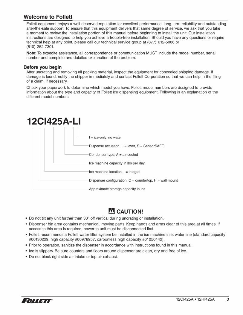
Check your paperwork to determine which model you have . Follett model numbers are designed to provide information about the type and capacity of Follett ice dispensing equipment . Following is an explanation of the different model numbers .
12CI425A-LII = ice-only; no water
Dispense actuation, L = lever, S = SensorSAFE
Condenser type, A = air-cooled
Ice machine capacity in lbs per day
Ice machine location, I = integral
Dispenser configuration, C = countertop, H = wall mount
Approximate storage capacity in lbs
CAUTION! § Do not tilt any unit further than 30° off vertical during uncrating or installation .
§ Dispenser bin area contains mechanical, moving parts . Keep hands and arms clear of this area at all times . If access to this area is required, power to unit must be disconnected first .
§ Follett recommends a Follett water filter system be installed in the ice machine inlet water line (standard capacity #00130229, high capacity #00978957, carbonless high capacity #01050442) .
§ Prior to operation, sanitize the dispenser in accordance with instructions found in this manual .
§ Ice is slippery . Be sure counters and floors around dispenser are clean, dry and free of ice .
§ Do not block right side air intake or top air exhaust .
12CI425A•12HI425A 3

Specifications
air exhaust
16.00"(40.7 cm)
4.00"(10.2 cm)
3/8" FPTwater inlet
3/4" MPT drain
23.5"(59.7 cm)
18.00"(45.8 cm)
32.00"(82.6 cm)
airintake
Front View Side View Rear View
22.625"(57.5 cm)
power cord (NEMA 5-15)
Electrical § 115 V, 60 Hz, 1 phase, 11 .0A
§ Connect to a 15A dedicated circuit .
AmbientAir temp* 100 F/38 C Max . 50 F/10 C Min . Best performance below 80 F (27 C)
Water temp† 90 F/32 C Max . 45 F/4 C Min . Best performance below 70 F (21 C)
Water pressure 70 P .S .I ./5Bar Max . 10 P .S .I ./0 .7 Bar Min .
* Ambient air temperature is measured at the air-cooled condenser coil inlet .† Ambient water temperature is measured in the ice machine reservoir .
Plumbing12CI425A 12HI425A
Dispenser drain 3/4" MPT 3/4" MPT
Water inlet 3/8" FNPT 3/8" FNPT
Note: Water shut-off recommended within 10 ft . (3 m) of dispenser . Drain to be hard-piped and insulated . Maintain at least 1/4" per foot (20 mm per 1 m) run of slope .
Ventilation clearances § 6" (15 .3 cm) on right side of dispenser, 6" (15 .3 cm) at top for ventilation and 12" (30 .5 cm) at top recommended for service .
Note: Do not block right side air intake or top air exhaust .
Dry weight § 175 lb (79 .4 kg)
4 12CI425A•12HI425A
* Dow Corning is a registered trademark of Dow Corning Corporation in the United States and other countries .
Installation
Before you begin § All dispensers must be installed level in both directions to ensure proper operation .
§ Service and ventilation clearances: 6" (15 .3 cm) on right side of dispenser, 6" (15 .3 cm) at top for ventilation and 12" (30 .5 cm) at top recommended for service .
§ Countertop units installed without legs provide the option of taking utilities out bottom or back of dispenser (on wall mount units and countertop units with legs, utilities exit from back) . See counter cutout drawings for bottom exiting utilities on units with and without drain pans . For installations where utilities exit through back of dispenser, refer to back view drawings .
§ Wall mount models without drain pan are designed for use above sinks .
§ Counter depth must allow front of sink to be a minimum of 30 .00" (76 .2 cm) from wall .
Installing countertop dispensers without legs
1. Position dispenser in desired location, mark dispenser outline on counter and remove dispenser .
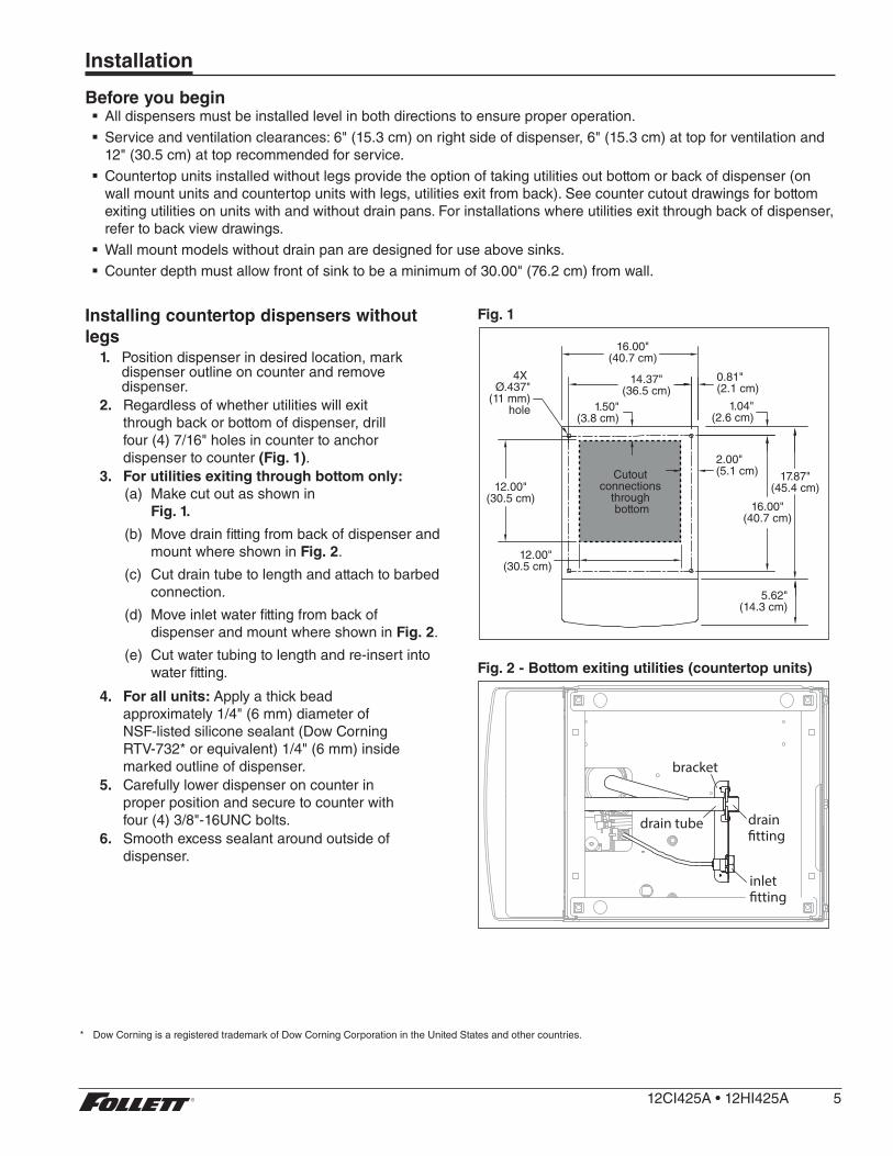
2. Regardless of whether utilities will exit through back or bottom of dispenser, drill four (4) 7/16" holes in counter to anchor dispenser to counter (Fig. 1) .
3. For utilities exiting through bottom only:(a) Make cut out as shown in
Fig. 1.
(b) Move drain fitting from back of dispenser and mount where shown in Fig. 2 .
(c) Cut drain tube to length and attach to barbed connection .
(d) Move inlet water fitting from back of dispenser and mount where shown in Fig. 2 .
(e) Cut water tubing to length and re-insert into water fitting .
4. For all units: Apply a thick bead approximately 1/4" (6 mm) diameter of NSF-listed silicone sealant (Dow Corning RTV-732* or equivalent) 1/4" (6 mm) inside marked outline of dispenser .
5. Carefully lower dispenser on counter in proper position and secure to counter with four (4) 3/8"-16UNC bolts .
6. Smooth excess sealant around outside of dispenser .
Fig. 1
2.00"(5.1 cm)
12.00"(30.5 cm)
14.37"(36.5 cm)
4X Ø.437"
(11 mm)hole 1.04"
(2.6 cm)
16.00"(40.7 cm)
Cutout connections
through bottom
12.00"(30.5 cm)
0.81"(2.1 cm)
16.00"(40.7 cm)
1.50"(3.8 cm)
17.87"(45.4 cm)
5.62"(14.3 cm)
Fig. 2 - Bottom exiting utilities (countertop units)
bracket
inlet �tting
drain�tting
drain tube
12CI425A•12HI425A 5
Installing countertop dispensers with legs accessory (P/N AF10LBLEGS)
CAUTION! § Do not tilt any unit further than 30° off vertical plane .
§ Countertop dispensers that sit on legs (not bolted to counter) can be inadvertently moved . Care should be taken when operating and cleaning to avoid accidents .
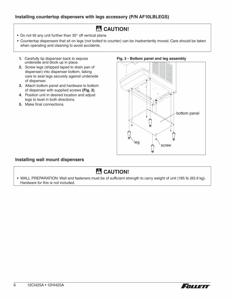
1. Carefully tip dispenser back to expose underside and block up in place .
2. Screw legs (shipped taped to drain pan of dispenser) into dispenser bottom, taking care to seat legs securely against underside of dispenser .
3. Attach bottom panel and hardware to bottom of dispenser with supplied screws (Fig. 3) .
4. Position unit in desired location and adjust legs to level in both directions .
5. Make final connections .
Fig. 3 - Bottom panel and leg assembly
bottom panel
screwleg
Installing wall mount dispensers
CAUTION! § WALL PREPARATION: Wall and fasteners must be of sufficient strength to carry weight of unit (185 lb (83 .9 kg) . Hardware for this is not included .
6 12CI425A•12HI425A
Notes:
§ SensorSAFE infrared dispensing is standard .
1. Recommended minimum counter depth and mounting height shown on Fig. 6 ensures that ice will drop into sink .
2. See Fig. 6 for model dimensions . The dimensions include the 0 .5" (13 mm) mounting bracket supplied with the unit .
3. Cut utility hole in wall as shown (Fig. 5) .4. Mount support bracket to wall using fasteners of sufficient strength (fasteners not included, see Fig. 4) .5. Rough in water and drain lines (3/4" copper recommended for drain) (Fig. 9) .6. Lift dispenser onto support bracket, positioning unit so that hook on back of dispenser is captured by support
bracket angle (Fig. 6) .7. Install two (2) supplied 3/8"-16UNC screws through bottom of support bracket into bottom of dispenser (Fig. 4) .
Slotted holes in support bracket allow you to adjust and level the dispenser . Ensure that the top of dispenser is level or tilted slightly back toward the wall .
8. Remove bottom cover and make final connections (Fig. 7) .9. Attach bottom panel and hardware to bottom of dispenser (Fig. 8) .10. Sanitize dispenser prior to use .
12CI425A•12HI425A 7

Fig. 4 – Wall mount bracket and fastener requirements
support bracket
screw
wall mounting bracket
= Customer supplied.
8 12CI425A•12HI425A

Fig. 5 – Wall-mount dimensions
ANCHOR POINTS0.438" (11 mm)CLEARANCE
FRONT VIEW
13.00" (33.0 cm)
16.00" TYP. (40.6 cm)
2.88" (7.3 cm)
2.88" (7.3 cm)13.50" (34.3 cm)
WALL CUTOUT
WALL STUDS
WALL MOUNTBRACKET
1.08" (2.7 cm)
8.08" (20.5 cm)
15.08" (38.3 cm)
Fig. 6 – Wall mount side view
20.53" (52.2 cm)18.51" (47.0 cm)
30.00" (76.2 cm)MIN DISTANCE TO SINK FRONT
23.70"(60.2 cm)
SUGGESTED POWERCORD ROUTING
32.00" (81.3 cm)
CAUTION! § Do not rest dispenser weight on bottom of support bracket . Dispenser weight to rest on top of the support bracket (Fig. 6) .
12CI425A•12HI425A 9

Fig. 7 – Wall mount unit bottom panel assembly
3/8” FNPT Water
3/4” MNPT Drain
BOTTOM VIEW
Fig. 8 – Wall mount unit bottom panel assembly
nut
support bracket
screwbottom panel
Fig. 9 – Wall mount, utility location
FRONT VIEW
WALL MOUNTBRACKET
3.70" (9.4 cm)POTABLE WATER SUPPLY
3/8 COPPER TUBE
7.88" (20.0 cm)DRAIN
3/4 COPPER TUBE11.75" (29.9 cm)POWER CORD EXIT
1.41" (3.6 cm)
0.92" (23 mm)
1.72" (4.4 cm)
WALLCUTOUT
water and drain tubing
(7.7 m)MAX.
3.00"
WALL
SIDE VIEW UTILITIES EXITING WALL
10 12CI425A•12HI425A
User information
How the dispenser worksFollett’s 12 series automatic-load ice and water dispensers are equipped with Follett’s 425 lb (193 kg)/day ice machine . In the continuous icemaking process, water freezes to the inside wall of the evaporator . A rotating stainless steel auger carries the ice to the top of the evaporator where it is compressed and extruded through an outlet port . The ice is then pushed through a tube to the storage hopper . When the hopper is full, a bin thermostat opens and shuts the ice machine off . When the dispense mechanism is activated, a dispense motor is turned on, causing the wheel to turn . This moves ice to the dispense chute where it drops by gravity into the container held below the chute .
How SensorSAFE infrared dispensing worksFollett’s SensorSAFE infrared dispensing maximizes sanitation and minimizes the possibility of cross-contamination by eliminating physical contact between the cup or container and dispenser . Sensors in the panel use reflected infrared light to detect the presence of the container and send a signal to a control board which then activates the appropriate components for ice or water dispensing .
The SensorSAFE infrared dispensing package includes a cleaning switch under the left side of the front cover which temporarily shuts off dispensing to allow cleaning of the panel and lenses . If the switch is not turned back on after cleaning, the dispenser automatically resets after two minutes for normal operation .
SensorSAFE infrared dispensing also includes a time limit safety feature which automatically stops ice dispensing after one minute of continuous dispensing . Dispensing can be resumed by moving the container away from the dispenser and returning it to the activation zone .
12CI425A•12HI425A 11
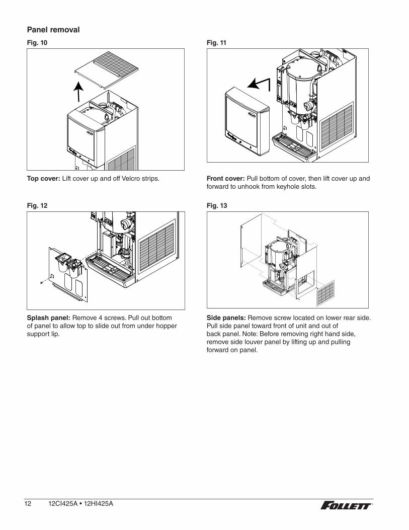
Panel removal
Fig. 10 Fig. 11
Top cover: Lift cover up and off Velcro strips . Front cover: Pull bottom of cover, then lift cover up and forward to unhook from keyhole slots .
Fig. 12 Fig. 13
Splash panel: Remove 4 screws . Pull out bottom of panel to allow top to slide out from under hopper support lip .
Side panels: Remove screw located on lower rear side . Pull side panel toward front of unit and out of back panel . Note: Before removing right hand side, remove side louver panel by lifting up and pulling forward on panel .
12 12CI425A•12HI425A
Cleaning/descaling and sanitizingFollett ice machines and dispensers, and their associated cleaning and sanitizing procedures, are designed for use with potable water sources . The presence, or suspected presence, of infectious agents may call for additional measures, including the replacement of components and more comprehensive disinfection measures . Follett recommends that these cleaning and sanitizing procedures be reviewed with the appropriate infectious agent subject matter experts to assure complete remediation .
Periodic cleaning/descaling and sanitizing of Follett’s ice and water dispenser and ice machine system is required to ensure peak performance and delivery of clean, sanitary ice . The recommended cleaning procedures that follow should be performed at least as frequently as recommended and more often if environmental conditions dictate .
Follett recommends sanitizing the pressurized water lines prior to cleaning/descaling and sanitizing the ice machine/dispenser . Follett offers two kits: order P/N 01089572 when a Follett filter system with a pre-filter bowl is present, or P/N 01089580 when a Follett filter system is not present . Follow the instructions provided with the respective kits to sanitize the pressurized water lines immediately before cleaning/descaling and sanitizing the ice machine/dispenser .
Cleaning of the condenser can usually be performed by facility personnel . Cleaning/descaling and sanitizing of the ice machine system should be performed by your facility’s trained maintenance staff or a Follett authorized service agent . Regardless of who performs the cleaning, it is the operator’s responsibility to see that this cleaning is performed according to the schedule below . Service problems resulting from lack of preventive maintenance will not be covered under the Follett warranty .
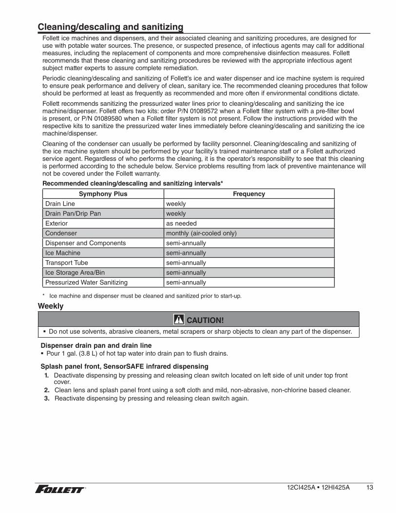
Recommended cleaning/descaling and sanitizing intervals*
Symphony Plus Frequency
Drain Line weekly
Drain Pan/Drip Pan weekly
Exterior as needed
Condenser monthly (air-cooled only)
Dispenser and Components semi-annually
Ice Machine semi-annually
Transport Tube semi-annually
Ice Storage Area/Bin semi-annually
Pressurized Water Sanitizing semi-annually
* Ice machine and dispenser must be cleaned and sanitized prior to start-up .
Weekly
CAUTION! § Do not use solvents, abrasive cleaners, metal scrapers or sharp objects to clean any part of the dispenser .
Dispenser drain pan and drain line § Pour 1 gal . (3 .8 L) of hot tap water into drain pan to flush drains .
Splash panel front, SensorSAFE infrared dispensing1. Deactivate dispensing by pressing and releasing clean switch located on left side of unit under top front
cover .2. Clean lens and splash panel front using a soft cloth and mild, non-abrasive, non-chlorine based cleaner .3. Reactivate dispensing by pressing and releasing clean switch again .
12CI425A•12HI425A 13

Monthly
CAUTION! § Do not use solvents, abrasive cleaners, metal scrapers or sharp objects to clean any part of the dispenser .
Condenser (air-cooled ice machine only)1. Use a vacuum cleaner or stiff brush to carefully clean condenser coils of lint and debris to ensure optimal
performance .
Semi-Annually (more often if conditions dictate) § A cleaning/descaling and sanitizing procedure should always include both the ice machine and dispenser .
§ Icemaking system can be cleaned/descaled in place .
CAUTION! § Wear rubber gloves and safety goggles (or face shield) when handling cleaner or sanitizer mixtures .
§ Use only Follett approved cleaners .
§ It is a violation of Federal law to use Cleaning or Sanitizing solutions in a manner inconsistent with their labeling .
§ Do not use solvents, abrasive cleaners, metal scrapers or sharp objects to clean any part of the dispenser .
Cleaning Solution: Mix cleaning solution of 1 gal . (3 .8 L) 100 F (38 C) water and 7 oz (198 g) (one 7 oz packet) of Follett SafeCLEAN ice machine cleaner/descaler (P/N 00132001) .
Sanitizing Solution: Mix a sanitizing solution of 1 gal . (3 .8 L) 100 F (38 C) water and 1 .6 oz (47 ml) Nu-Calgon IMS-II or IMS-III Sanitizer (P/N 00979674) .
Cleaning & sanitizing tool checklist § (2) 1 .5 Gallon (or larger) Plastic Buckets
§ (2) clean cloths
§ Sanitary gloves
§ Safety glasses
§ (2) Sani-Sponge™ (P/N 00131524 - single sponge)
§ (1 ) Packet of SafeCLEAN™ (P/N 00132001 - 24 packets)
§ 1 .6 fl oz of Nu-Calgon IMS-II or IMS-III Sanitizer (P/N 00979674 - 16 fl . oz bottle)
Ice Machine and DispenserCleaning/descaling procedure
Note: Check drains and drain cup to ensure they are open and flowing freely .
1. If ice machine was running recently, ensure that the evaporator is completely free of ice before proceeding . If there is ice in the evaporator, complete steps 2-7 using only hot water to remove the ice then begin Cleaning/Descaling Procedure again .
2. Remove front cover and turn OFF bin signal switch . 3. Dispense all ice from storage hopper and discard .4. Remove top of machine and hopper lid .5. Press CLEAN switch . The MAINTENANCE light will turn on and the machine will drain . Wait for the LOW
WATER light to turn on .6. Remove lid from cleaning cup and fill (about 1 quart) until cleaning solution overflows from the ice
transport tube into the hopper . Place lid back on cup . Save remainder of cleaning solution .7. CLEANER FULL light will turn on and machine will start cleaning cycle then rinse three times; this
process takes approximately 15 minutes .
14 12CI425A•12HI425A

8. While ice machine is cleaning/descaling, clean dispenser as follows:a . Remove center thumbscrew, locking plate, two wingnuts and backing plate from front of storage hopper .
b . Remove stud assembly, baffle, wheel, and any remaining ice .
c . Remove dispense chutes from splash panel .
d . Submerse drain grille in cleaning solution and allow to soak to remove any scale buildup .
e . Wipe stud assembly, baffle, wheel, inside of storage area, dispense chutes, drain grille and drain pan with damp cloth wrung out in cleaning solution . Thoroughly rinse all parts with damp cloth wrung out with clean water .
Note: To avoid possible damage to motor assembly, only use a damp cloth to clean storage hopper . Do not allow water to run through motor shaft hole in bottom of hopper .
9. When machine is finished cleaning, the MAINTENANCE light will turn off .
Sanitizing procedure10. Press CLEAN switch . The MAINTENANCE light and LOW WATER light will turn on .11. Fill cleaning cup with sanitizing solution until it overflows from the ice transport tube into the hopper . Place
lid back on cup . Save remainder of sanitizing solution .12. CLEANER FULL light will turn on and machine will start sanitizing cycle then rinse three times; this
process takes approximately 15 minutes . 13. While ice machine is sanitizing, sanitize dispenser as follows:
a . Wipe inside of hopper lid, stud assembly, baffle, wheel, inside of storage area, dispense chutes, drain grille and drain pan with damp cloth wrung out in sanitizing solution .
Note: To avoid possible damage to motor assembly, only use a damp cloth to clean storage hopper . Do not allow water to run through motor shaft hole in bottom of hopper .
b . Reinstall dispense chutes, wheel, baffle, stud assembly, backing plate, two wing nuts, locking plate, and thumbscrew . (See manual for correct baffle position .)
14. When machine is finished rinsing, the MAINTENANCE light will turn off . Remove top bearing insulation and compression nozzle insulation . Loosen Phillips-head screw on nozzle connected to evaporator . Remove nozzle from evaporator side only, leave other side of nozzle connected to transport tube .
15. Place one Sani-Sponge in remaining sanitizing solution .16. Insert the sponge soaked in sanitizing solution into nozzle then insert a dry sponge into the nozzle .17. Replace nozzle onto evaporator and tighten screw . Ensure drain is connected to reservoir and vent tubes
are connected to evaporator drain pan . 18. Turn ON bin signal switch . Wait for ice to push sponges through transport tube .19. Collect sponges from ice storage bin .20. Replace hopper lid, machine top, and install front cover .21. After 10 minutes, dispense all ice and discard .
User Interface and Exterior Cabinet § Clean stainless steel panels with stainless steel cleaner .
12CI425A•12HI425A 15

Service
Ice machine operation (all models)Follett’s ice machine consists of four distinct functional systems:
§ Harvesting system
§ Water system
§ Electrical control system
§ Refrigeration systemThese four systems work together to accomplish the production and harvesting of ice . A problem in any one of these systems will result in improper operation of the entire ice production cycle . When troubleshooting the ice machine, it is important to analyze the entire system operation to determine which system is not functioning properly, then pinpoint the component within that system that is malfunctioning . Determine what corrective action must be taken before making any adjustments or replacing any components .
The icemaking processThe Maestro Plus ice machine uses a stainless steel jacketed evaporator and operates on a continuous freezing cycle . Water is supplied to the evaporator from the water reservoir where the water level is controlled by conductivity probes .
When the ice machine is running, a layer of ice forms on the interior surface of the evaporator . This ice is continuously removed by a slowly rotating (12 RPM) auger . The auger carries the ice upward into the cavity formed by the top bearing housing and the compression loop, where it is compressed to remove excess water . When the ice reaches the desired hardness it rotates within the cavity and is forced through a discharge port and compression nozzle and into the ice transport tube . The discharge tube and compression nozzle are slightly restricted to further compress the ice and produce the desired hardness .
A solid state control board located in the electrical box of the ice machine controls the normal operation of the ice machine and monitors gearmotor torque . This control board will shut down the ice machine should an over-torque condition occur . It is very important that you familiarize yourself with the operational sequences detailed in this manual before attempting to service the ice machine .
WATERINLET
AUGER
COMPRESSION NOZZLE
ICE TRANSPORT TUBE
EVAPORATORPORT
16 12CI425A•12HI425A

Water systemThe water level in the evaporator is controlled by a fill solenoid (Fig. 14) and level detecting sensors . Water sensing rods (Fig. 15) extend down into the reservoir at the end of the evaporator assembly . The system works via electrical conductivity as follows:
One of the longest probes is a common . When water is between any of the other probes and the common, the PC board will sense the activation . During normal operation, the water level rises and falls between the Normal High and Normal Low sensors . As water is consumed to make ice, the level will fall until the Normal Low sensor is exposed, triggering the water feed solenoid on . Water will fill until the Normal High sensor is activated .
Note: The potable water dissolved solids content must be greater than 10 ppm for the water control system to function properly . If using reverse osmosis water filtration system, ensure T .D .S level is greater than 10 ppm .
Fig. 14 – Water system diagram
CLEANING CUP
WATER SUPPLY3/8" FPT, 45-90 F (7-32 C)10-70 PSI (69-483 KPA)
RESERVOIR FILLSOLENOID
WATERRESERVOIR
EV
AP
OR
ATO
R
ICENOZZLE
DRAIN PAN
VENT
TO DRAIN CUP
Fig. 15 – Water level diagram
B A
CD
B: COMMON (BLACK)C: HIGH (ORANGE)A: ALARM LOW (RED)D: LOW (YELLOW) NORMAL OPERATING RANGE
12CI425A•12HI425A 17

Access to electrical box and control boardThe 12 series electrical box has been designed to slide out for easy access to the control board and more convenient troubleshooting .
1. Remove top and front panels of dispenser (for panel removal instructions see page 12) .
2. Remove electrical box cover .3. Pull electrical box toward front of unit .
Fig. 16
electrical box
electricalcover
Electrical system
ATTENTION!
To prevent circuit breaker overload, wait 15 minutes before restarting this unit. This allows the compressor to equalize and the evaporator to thaw.
Normal control board operationThe PC board indicator lights provide all the information necessary to determine the machine's status . Green indicator lights generally represent “go” or normal operation; Yellow indicators represent normal off conditions; Red indicators generally represent alarm conditions, some of which will lock the machine off .
A flashing green light labeled POWER indicates power to the machine . All other normal operation status indicators are covered as follows:
Ice machine disposition Operating conditions
FLASHINGON or OFFLegend: OFFON
1 . Ice machine is making ice . 1 . Normal running.
2 . Ice machine is not making ice . 2 . Normal time delay. When the bin fills with ice, the LOW BIN light goes out momentarily and the refrigeration and auger drive systems immediately shut down . (Note: The fan motor will continue to run for 10 minutes to cool condenser) The TIME DELAY light comes on, initiating the time delay period . When the time delay expires, the machine will restart provided that the LOW BIN light is on .
18 12CI425A•12HI425A
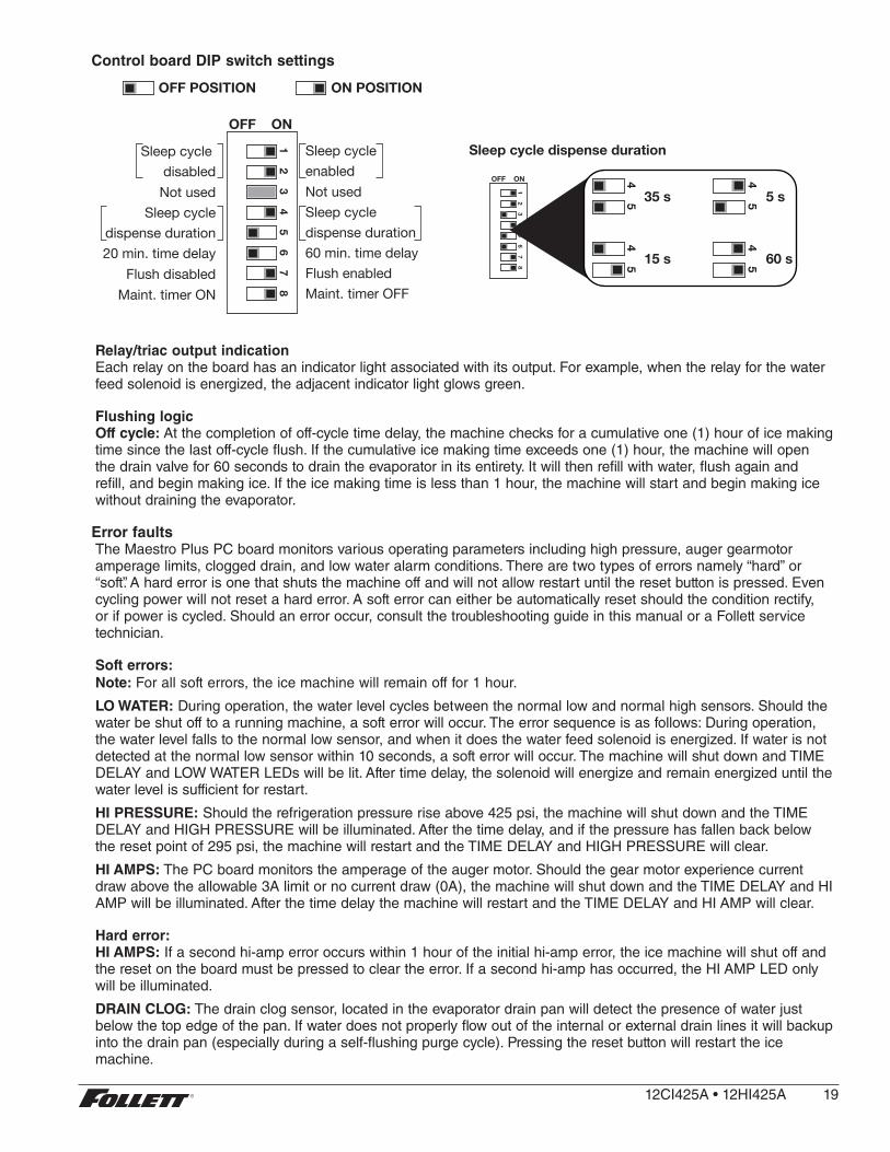
Control board DIP switch settings
Sleep cycle dispense duration
OFF ON
12
34
56
78
45
45
45
45
35 s
15 s
5 s
60 s
Sleep cycle enabledNot usedSleep cycledispense duration60 min. time delayFlush enabledMaint. timer OFF
OFF ON
Sleep cycle disabled
Not usedSleep cycle
dispense duration20 min. time delay
Flush disabledMaint. timer ON
12
34
56
78
OFF POSITION ON POSITION
Relay/triac output indicationEach relay on the board has an indicator light associated with its output . For example, when the relay for the water feed solenoid is energized, the adjacent indicator light glows green .
Flushing logicOff cycle: At the completion of off-cycle time delay, the machine checks for a cumulative one (1) hour of ice making time since the last off-cycle flush . If the cumulative ice making time exceeds one (1) hour, the machine will open the drain valve for 60 seconds to drain the evaporator in its entirety . It will then refill with water, flush again and refill, and begin making ice . If the ice making time is less than 1 hour, the machine will start and begin making ice without draining the evaporator .
Error faultsThe Maestro Plus PC board monitors various operating parameters including high pressure, auger gearmotor amperage limits, clogged drain, and low water alarm conditions . There are two types of errors namely “hard” or “soft” . A hard error is one that shuts the machine off and will not allow restart until the reset button is pressed . Even cycling power will not reset a hard error . A soft error can either be automatically reset should the condition rectify, or if power is cycled . Should an error occur, consult the troubleshooting guide in this manual or a Follett service technician .
Soft errors:Note: For all soft errors, the ice machine will remain off for 1 hour .
LO WATER: During operation, the water level cycles between the normal low and normal high sensors . Should the water be shut off to a running machine, a soft error will occur . The error sequence is as follows: During operation, the water level falls to the normal low sensor, and when it does the water feed solenoid is energized . If water is not detected at the normal low sensor within 10 seconds, a soft error will occur . The machine will shut down and TIME DELAY and LOW WATER LEDs will be lit . After time delay, the solenoid will energize and remain energized until the water level is sufficient for restart .
HI PRESSURE: Should the refrigeration pressure rise above 425 psi, the machine will shut down and the TIME DELAY and HIGH PRESSURE will be illuminated . After the time delay, and if the pressure has fallen back below the reset point of 295 psi, the machine will restart and the TIME DELAY and HIGH PRESSURE will clear .
HI AMPS: The PC board monitors the amperage of the auger motor . Should the gear motor experience current draw above the allowable 3A limit or no current draw (0A), the machine will shut down and the TIME DELAY and HI AMP will be illuminated . After the time delay the machine will restart and the TIME DELAY and HI AMP will clear .
Hard error:HI AMPS: If a second hi-amp error occurs within 1 hour of the initial hi-amp error, the ice machine will shut off and the reset on the board must be pressed to clear the error . If a second hi-amp has occurred, the HI AMP LED only will be illuminated .
DRAIN CLOG: The drain clog sensor, located in the evaporator drain pan will detect the presence of water just below the top edge of the pan . If water does not properly flow out of the internal or external drain lines it will backup into the drain pan (especially during a self-flushing purge cycle) . Pressing the reset button will restart the ice machine .
12CI425A•12HI425A 19
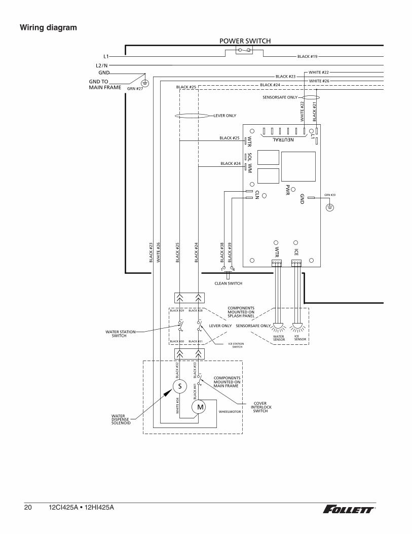
Wiring diagram
WATER LEVELSP17
BINP12 CLEAN SAFEP11
POWERLOW BINMAKING ICESLEEP CYCLETIME DELAYLOW WATERMAINTENANCESERVICEHI AMPSHI PRESSURE
CLEANER FULL
RESERVOIRWATER SENSOR
MAINT.CLEAN
HI PRSP14
HIGHPRESS
P
L1
GNDL2/N
BIN LEVELT-STAT
A B C D
BLACKYELLOW
ORANGERED
BIN SIGNALSWITCHMOUNTED ON
SPLASH PANEL
SOL
WTR
NEUTRAL
COMPONENTS
SENSORWATER
SENSORICE
CLN
WM
PWR
WTR
L1
GN
DIC
E
WHITE
BLUE
BISON GEARMOTORSTARTRELAY
3
4 2
YELLOW
BLACK
T.O.L.
START
RUN
FAN
FEED VALVE
DRAIN VALVE
RED
#16
BR
OW
N #
14B
LAC
K #
36B
LUE
#07
GRN #17
GRN #27BLACK #51
BLACK #23
BLACK #18
BLA
CK
#21
WH
ITE
#22
BLACK #25
GRN #20
BLA
CK
#23
WH
ITE
#26
BLA
CK
#25
BLA
CK
#24
BLA
CK
#38
BLA
CK
#39
GND TO MAIN FRAME
POWER SWITCH
BLA
CK
#51
WH
ITE
#52
COMP.R
CS
O.L.
C2 START1 2 3 4 5 6 7 8 9
GR
EEN
#53
COMPRESSOR
COMPRESSORELECTRICAL
BOX
BLA
CK
#51
WH
ITE
#52
GR
EEN
#53
RED
#54
OR
AN
GE
#55
BLA
CK
#56
GREEN #57BLACK #58BLACK #59
LEVER ONLY
SENSORSAFE ONLY
BLACK #24
BLACK #25
BLA
CK
#24
BLACK #21 (SENSORSAFE)BLACK #25 (LEVER)
CLEAN SWITCH
41
6
4 1
25
BLA
CK
#61
WH
ITE
#62
GR
EEN
#63
WH
ITE
#64
BLA
CK
#65
BLA
CK
#66
GR
EEN
#67
BLA
CK
#68
BLA
CK
#69
C1 RUN
WHEELMOTORM
COMPONENTSMOUNTED ONMAIN FRAME4
1
BLA
CK
#33
BLA
CK
#41S
BLA
CK
#32
WH
ITE
#34
WATERDISPENSESOLENOID
BLACK #28
BLACK #31
41
BLACK #29
41
BLACK #30
LEVER ONLY
WH
ITE
#05
WH
ITE
#35
WH
ITE
#13
WH
ITE
#15
SENSORSAFE ONLY
BLACK #66BLACK #69
BLACK #71
MODEL SELECT
SERIAL COMM
COM
PRES
SOR
AUGER
WATER LEVELS
HI PRS
BIN RS485
RS485 UI
CURRENT SENS RESET
PROGRAM
P5
ICE AUX WATER AUX
D9
D8
D7
D6
D5
D4
D37
D3
D2
D18
D16
D15
D14
D13
D12
D11
D10
D1
T1
P18
P11 P13
P17
P12
P14
P16P15
P4T2
S1
S2
K1
P7
P8
P10
K312 6
5
P9
L1L1
L1
N N N N N N N N NP2
P1
P21
P20
P19
P3
BLACK #01
P6
P22
D19
D22
D21
D20
D17
D48
WATER STATIONSWITCH
ICE STATIONSWITCH
COVERINTERLOCK
SWITCH
BLACK #19 BLACK #19
BLACK #23WHITE #22
WHITE #26BLACK #23
WHITE #22
WHITE #26BLACK #24 BLACK #24
BLA
CK
BLA
CK
20 12CI425A•12HI425A

WATER LEVELSP17
BINP12 CLEAN SAFEP11
POWERLOW BINMAKING ICESLEEP CYCLETIME DELAYLOW WATERMAINTENANCESERVICEHI AMPSHI PRESSURE
CLEANER FULL
RESERVOIRWATER SENSOR
MAINT.CLEAN
HI PRSP14
HIGHPRESS
P
L1
GNDL2/N
BIN LEVELT-STAT
A B C D
BLACKYELLOW
ORANGERED
BIN SIGNALSWITCHMOUNTED ON
SPLASH PANEL
SOL
WTR
NEUTRAL
COMPONENTS
SENSORWATER
SENSORICE
CLN
WM
PWR
WTR
L1
GN
DIC
E
WHITE
BLUE
SPLIT-PHASESTARTRELAY
3
4 2
YELLOW
BLACK
T.O.L.
START
RUN
FAN
FEED VALVE
DRAIN VALVE
RED
#16
BR
OW
N #
14B
LAC
K #
36B
LUE
#07
GRN #17
GRN #27BLACK #51
BLACK #23
BLACK #18
BLA
CK
#21
WH
ITE
#22
BLACK #25
GRN #20
BLA
CK
#23
WH
ITE
#26
BLA
CK
#25
BLA
CK
#24
BLA
CK
#38
BLA
CK
#39
GND TO MAIN FRAME
POWER SWITCHB
LAC
K #
51W
HIT
E #5
2
COMP.R
CS
O.L.
C2 START1 2 3 4 5 6 7 8 9
GR
EEN
#53
COMPRESSOR
COMPRESSORELECTRICAL
BOX
BLA
CK
#51
WH
ITE
#52
GR
EEN
#53
RED
#54
OR
AN
GE
#55
BLA
CK
#56
GREEN #57BLACK #58BLACK #59
LEVER ONLY
SENSORSAFE ONLY
BLACK #24
BLACK #25
BLA
CK
#24
BLACK #21 (SENSORSAFE)BLACK #25 (LEVER)
CLEAN SWITCH
41
6
4 1
25
BLA
CK
#61
WH
ITE
#62
GR
EEN
#63
WH
ITE
#64
BLA
CK
#65
BLA
CK
#66
GR
EEN
#67
BLA
CK
#68
BLA
CK
#69
C1 RUN
WHEELMOTORM
COMPONENTSMOUNTED ONMAIN FRAME4
1
BLA
CK
#33
BLA
CK
#41S
BLA
CK
#32
WH
ITE
#34
WATERDISPENSESOLENOID
BLACK #28
BLACK #31
41
BLACK #29
41
BLACK #30
LEVER ONLY
WH
ITE
#05
WH
ITE
#35
WH
ITE
#13
WH
ITE
#15
SENSORSAFE ONLY
BLACK #66BLACK #69
BLACK #71
MODEL SELECT
SERIAL COMM
COM
PRES
SOR
AUGER
WATER LEVELS
HI PRS
BIN RS485
RS485 UI
CURRENT SENS RESET
PROGRAM
P5
ICE AUX WATER AUX
D9
D8
D7
D6
D5
D4
D37
D3
D2
D18
D16
D15
D14
D13
D12
D11
D10
D1
T1
P18
P11 P13
P17
P12
P14
P16P15
P4T2
S1
S2
K1
P7
P8
P10
K312 6
5
P9
L1L1
L1
N N N N N N N N NP2
P1
P21
P20
P19
P3
BLACK #01
P6
P22
D19
D22
D21
D20
D17
D48
WATER STATIONSWITCH
ICE STATIONSWITCH
COVERINTERLOCK
SWITCH
BLACK #19 BLACK #19
BLACK #23WHITE #22
WHITE #26BLACK #23
WHITE #22
WHITE #26BLACK #24 BLACK #24
BLA
CK
BLA
CK OR
BLUE
CAPACITOR
T.O.L.
START
RUN
BLACK
YELLOW
PSC MOTOR
12CI425A•12HI425A 21

Wiring diagram - Lever only
L1
GNDL2/N
MOUNTED ONSPLASH PANEL
COMPONENTS
GRN #27BLACK #25
BLA
CK
#23
WH
ITE
#26
BLA
CK
#25
BLA
CK
#24
GND TO MAIN FRAME
POWER SWITCH
WHEELMOTORM
COMPONENTSMOUNTED ONMAIN FRAME4
1
BLA
CK
#33
BLA
CK
#41S
BLA
CK
#32
WH
ITE
#34
WATERDISPENSESOLENOID
BLACK #28
BLACK #31
41
BLACK #29
41
BLACK #30
LEVER ONLYWATER STATIONSWITCH
ICE STATIONSWITCH
COVERINTERLOCK
SWITCH
BLACK #19
BLACK #23WHITE #26
BLACK #24
22 12CI425A•12HI425A
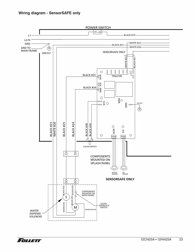
Wiring diagram - SensorSAFE only
SOL
WTR
NEUTRALSENSORWATER
SENSORICE
CLN
WM
PWR
WTR
L1
GN
DIC
E
BLA
CK
#21
WH
ITE
#22
GRN #20
BLA
CK
#38
BLA
CK
#39
POWER SWITCH
SENSORSAFE ONLY
BLACK #24
BLACK #25
CLEAN SWITCH
41
WHEELMOTORM
41
S
SENSORSAFE ONLY
BLACK #19
BLACK #23WHITE #22
WHITE #26
L1
GNDL2/N
MOUNTED ONSPLASH PANEL
COMPONENTS
GRN #27B
LAC
K #
23W
HIT
E #2
6
BLA
CK
#25
BLA
CK
#24
GND TO MAIN FRAME
COMPONENTSMOUNTED ONMAIN FRAMEB
LAC
K #
33B
LAC
K #
41
BLA
CK
#32
WH
ITE
#34
WATERDISPENSESOLENOID
COVERINTERLOCK
SWITCH
12CI425A•12HI425A 23

Ice machine operational and diagnostic sequencesThe wiring diagrams that follow illustrate the circuitry of Follett ice machines used with 12 series ice dispensers . Both normal operation (stages 1–8) and non-normal diagnostic sequences showing torque-out for use in troubleshooting are shown .
Circuitry notes § Bin signal is contact closure only - DO NOT SUPPLY POWER .
Note: The operation stage descriptions that follow are based on the unit containing the split-phase gear motor.
Normal operation – Stage 1Power is supplied to L1 of the control board, the POWER LED light begins flashing . The ice level bin thermostat in the dispenser is closed and calling for ice, supplying contact closure to the control board . The LOW BIN LED will be on . The control board will now go through the start-up sequence . The board checks the water sensors (located in the reservoir) for continuity between the common probe (B) and the high probe (C) . If continuity is not sensed, the water fill valve (P21) is energized .
Compressor
MAINTENANCE
LOW WATER
TIME DELAY
SLEEP CYCLE
MAKING ICE
LOW BIN
POWER
SERVICE
HI AMPS
HI PRESSURE
CLEANER FULL
Gearmotor
Water Sensors
Clean Switch
High Pressure Switch
Start Relay
OR
Capacitor
BLA
CK
YELLOW
NO
CO
NN
ECT
24 12CI425A•12HI425A
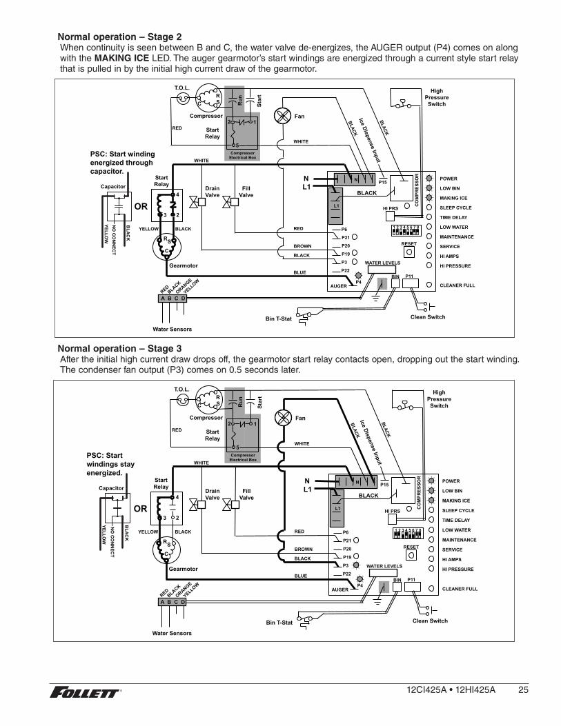
Normal operation – Stage 2When continuity is seen between B and C, the water valve de-energizes, the AUGER output (P4) comes on along with the MAKING ICE LED . The auger gearmotor’s start windings are energized through a current style start relay that is pulled in by the initial high current draw of the gearmotor .
5
2 1
Star
t
Run
Compressor
T.O.L.
MAINTENANCE
LOW WATER
TIME DELAY
SLEEP CYCLE
MAKING ICE
LOW BIN
POWER
SERVICE
HI AMPS
HI PRESSURE
CLEANER FULL
High Pressure Switch
R S C
Gearmotor
Start Relay
Start Relay
N L1
Fan
A B C D
Water Sensors
RESET
Fill Valve
Drain Valve
3
4
2
Bin T-Stat Clean Switch
P6
P21
P20
P19
P3
P22
P4 AUGER
WATER LEVELS
BIN P11
HI PRS L1
R S C
RED
WHITE
WHITE
BLACK
BROWN
BLUE
RED BLACK YELLOW
Compressor Electrical Box
CO
MPR
ESSO
R
1 2 3 4 5 6 7 8
BLACK
N P15
Ice Dispense Input
OR
Capacitor
BLA
CK
YELLOW
NO
CO
NN
ECT
PSC: Start winding energized through capacitor.
Normal operation – Stage 3After the initial high current draw drops off, the gearmotor start relay contacts open, dropping out the start winding . The condenser fan output (P3) comes on 0 .5 seconds later .
5
2 1
Star
t
Run
Compressor
T.O.L.
MAINTENANCE
LOW WATER
TIME DELAY
SLEEP CYCLE
MAKING ICE
LOW BIN
POWER
SERVICE
HI AMPS
HI PRESSURE
CLEANER FULL
High Pressure Switch
R S C
Gearmotor
Start Relay
Start Relay
N L1
Fan
A B C D
Water Sensors
RESET
Fill Valve
Drain Valve
3
4
2
Bin T-Stat Clean Switch
P6
P21
P20
P19
P3
P22
P4 AUGER
WATER LEVELS
BIN P11
HI PRS L1
R S C
RED
WHITE
WHITE
BLACK
BROWN
BLUE
RED BLACK YELLOW
Compressor Electrical Box
CO
MPR
ESSO
R
1 2 3 4 5 6 7 8
BLACK
N P15
Ice Dispense Input
OR
Capacitor
BLA
CK
YELLOW
NO
CO
NN
ECT
PSC: Start windings stay energized.
12CI425A•12HI425A 25
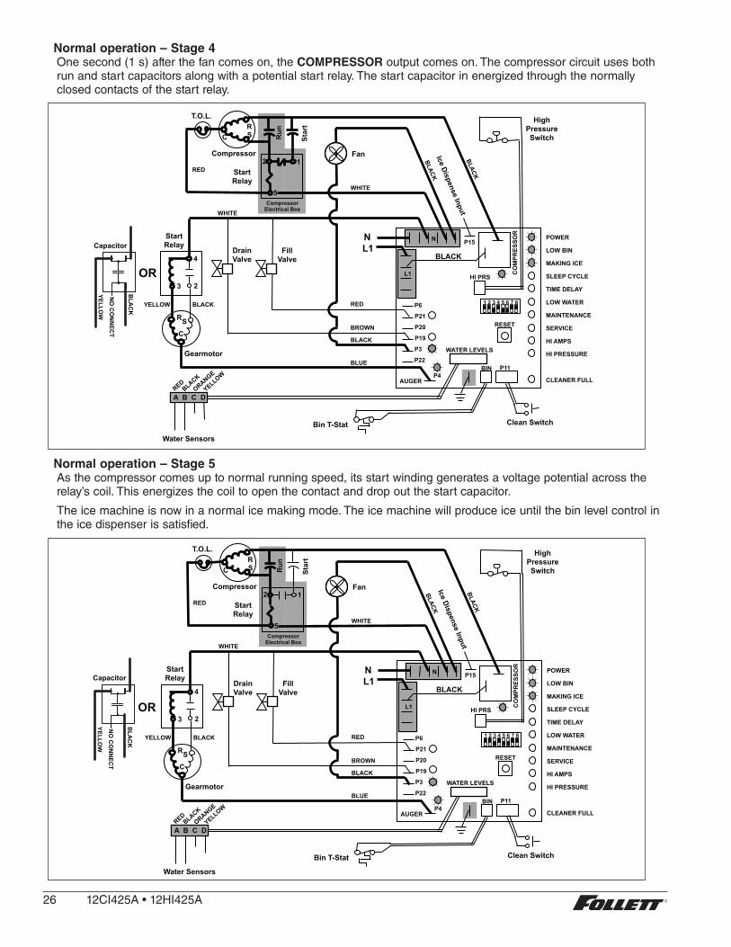
Normal operation – Stage 4One second (1 s) after the fan comes on, the COMPRESSOR output comes on . The compressor circuit uses both run and start capacitors along with a potential start relay . The start capacitor in energized through the normally closed contacts of the start relay .
5
2 1
Star
t
Run
Compressor
T.O.L.
MAINTENANCE
LOW WATER
TIME DELAY
SLEEP CYCLE
MAKING ICE
LOW BIN
POWER
SERVICE
HI AMPS
HI PRESSURE
CLEANER FULL
High Pressure Switch
R S C
Gearmotor
Start Relay
Start Relay
N L1
Fan
A B C D
Water Sensors
RESET
Fill Valve
Drain Valve
3
4
2
Bin T-Stat Clean Switch
P6
P21
P20
P19
P3
P22
P4 AUGER
WATER LEVELS
BIN P11
HI PRS L1
R S C
RED
WHITE
WHITE
BLACK
BROWN
BLUE
RED BLACK YELLOW
Compressor Electrical Box
CO
MPR
ESSO
R
1 2 3 4 5 6 7 8
BLACK
N P15
Ice Dispense InputOR
Capacitor
BLA
CK
YELLOW
NO
CO
NN
ECT
Normal operation – Stage 5As the compressor comes up to normal running speed, its start winding generates a voltage potential across the relay’s coil . This energizes the coil to open the contact and drop out the start capacitor .
The ice machine is now in a normal ice making mode . The ice machine will produce ice until the bin level control in the ice dispenser is satisfied .
5
2 1
Star
t
Run
Compressor
T.O.L.
MAINTENANCE
LOW WATER
TIME DELAY
SLEEP CYCLE
MAKING ICE
LOW BIN
POWER
SERVICE
HI AMPS
HI PRESSURE
CLEANER FULL
High Pressure Switch
R S C
Gearmotor
Start Relay
Start Relay
N L1
Fan
A B C D
Water Sensors
RESET
Fill Valve
Drain Valve
3
4
2
Bin T-Stat Clean Switch
P6
P21
P20
P19
P3
P22
P4 AUGER
WATER LEVELS
BIN P11
HI PRS L1
R S C
RED
WHITE
WHITE
BLACK
BROWN
BLUE
RED BLACK YELLOW
Compressor Electrical Box
CO
MPR
ESSO
R
1 2 3 4 5 6 7 8
BLACK
N P15
Ice Dispense Input
OR
Capacitor
BLA
CK
YELLOW
NO
CO
NN
ECT
26 12CI425A•12HI425A
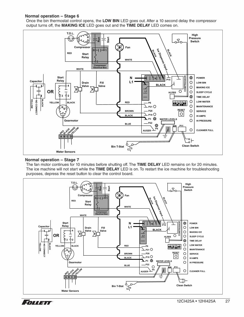
Normal operation – Stage 6Once the bin thermostat control opens, the LOW BIN LED goes out . After a 10 second delay the compressor output turns off, the MAKING ICE LED goes out and the TIME DELAY LED comes on .
5
2 1
Star
t
Run
Compressor
T.O.L.
MAINTENANCE
LOW WATER
TIME DELAY
SLEEP CYCLE
MAKING ICE
LOW BIN
POWER
SERVICE
HI AMPS
HI PRESSURE
CLEANER FULL
High Pressure Switch
R S C
Gearmotor
Start Relay
Start Relay
N L1
Fan
A B C D
Water Sensors
RESET
Fill Valve
Drain Valve
3
4
2
Bin T-Stat Clean Switch
P6
P21
P20
P19
P3
P22
P4 AUGER
WATER LEVELS
BIN P11
HI PRS L1
R S C
RED
WHITE
WHITE
BLACK
BROWN
BLUE
RED BLACK YELLOW
Compressor Electrical Box
CO
MPR
ESSO
R
1 2 3 4 5 6 7 8
BLACK
N P15
Ice Dispense InputCapacitor
BLA
CK
YELLOW
OR
NO
CO
NN
ECT
Normal operation – Stage 7The fan motor continues for 10 minutes before shutting off . The TIME DELAY LED remains on for 20 minutes . The ice machine will not start while the TIME DELAY LED is on . To restart the ice machine for troubleshooting purposes, depress the reset button to clear the control board .
5
2 1
Star
t
Run
Compressor
T.O.L.
MAINTENANCE
LOW WATER
TIME DELAY
SLEEP CYCLE
MAKING ICE
LOW BIN
POWER
SERVICE
HI AMPS
HI PRESSURE
CLEANER FULL
High Pressure Switch
R S C
Gearmotor
Start Relay
Start Relay
N L1
Fan
A B C D
Water Sensors
RESET
Fill Valve
Drain Valve
3
4
2
Bin T-Stat Clean Switch
P6
P21
P20
P19
P3
P22
P4 AUGER
WATER LEVELS
BIN P11
HI PRS L1
R S C
RED
WHITE
WHITE
BLACK
BROWN
BLUE
RED BLACK YELLOW
Compressor Electrical Box
CO
MPR
ESSO
R
1 2 3 4 5 6 7 8
BLACK
N P15
Ice Dispense Input
OR
Capacitor
BLA
CK
YELLOW
NO
CO
NN
ECT
12CI425A•12HI425A 27

Normal operation – Stage 8When the dwell time of 20 minutes has expired, the TIME DELAY LED goes off . If 5 seconds of ice has been dispensed and the SLEEP CYCLE LED (Symphony Plus only) is off, the ice machine will go through the normal start-up sequence when the bin level control signals the control board for ice .
5
2 1
Star
t
Run
Compressor
T.O.L.
MAINTENANCE
LOW WATER
TIME DELAY
SLEEP CYCLE
MAKING ICE
LOW BIN
POWER
SERVICE
HI AMPS
HI PRESSURE
CLEANER FULL
High Pressure Switch
R S C
Gearmotor
Start Relay
Start Relay
N L1
Fan
A B C D
Water Sensors
RESET
Fill Valve
Drain Valve
3
4
2
Bin T-Stat Clean Switch
P6
P21
P20
P19
P3
P22
P4 AUGER
WATER LEVELS
BIN P11
HI PRS L1
R S C
RED
WHITE
WHITE
BLACK
BROWN
BLUE
RED BLACK YELLOW
Compressor Electrical Box
CO
MPR
ESSO
R
1 2 3 4 5 6 7 8
BLACK
N P15
Ice Dispense InputOR
Capacitor
BLA
CK
YELLOW
NO
CO
NN
ECT
Quiet Night™/Sleep cycle (Symphony Plus only)The board monitors ice dispensing through a line voltage input to P15 . If the ice dispense has not be initiated for more than 5 seconds during the 20 minute time delay, the SLEEP CYCLE LED comes on . The machine will stay off for 12 hours unless 5 seconds of dispensing is seen . After 12 hours, the SLEEP CYCLE LED goes out and the ice making will resume if the bin thermostat is closed . The sleep cycle dispense duration is adjustable using the DIP switches on the control board .
Self-flushing (when enabled)At the completion of the 20 minute time delay, the machine checks for a cumulative one hour of ice making time since the last off-cycle flush . If the cumulative ice making time exceeds one hour, the machine will energize the drain valve P19 for 60 seconds to drain the evaporator . It will then refill with water, flush again, refill and begin making ice if the LOW BIN LED is on . If the ice making time is less than 1 hour, the machine will start and begin making ice without draining the evaporator .
28 12CI425A•12HI425A

5
2 1
Star
t
Run
Compressor
T.O.L.
MAINTENANCE
LOW WATER
TIME DELAY
SLEEP CYCLE
MAKING ICE
LOW BIN
POWER
SERVICE
HI AMPS
HI PRESSURE
CLEANER FULL
High Pressure Switch
R S C
Gearmotor
Start Relay
Start Relay
N L1
Fan
A B C D
Water Sensors
RESET
Fill Valve
Drain Valve
3
4
2
Bin T-Stat Clean Switch
P6
P21
P20
P19
P3
P22
P4 AUGER
WATER LEVELS
BIN P11
HI PRS L1
R S C
RED
WHITE
WHITE
BLACK
BROWN
BLUE
RED BLACK YELLOW
Compressor Electrical Box
CO
MPR
ESSO
R
1 2 3 4 5 6 7 8
BLACK
N P15
Ice Dispense Input
OR
Capacitor
BLA
CK
YELLOW
NO
CO
NN
ECT
Diagnostic stagesHigh gearmotor amps – Stage 1The HI AMPS error and TIME DELAY LEDs are on indicating that the control board has sensed an over-torque condition at the P4 terminal (more than 3 amps from the gearmotor) or no current draw (0A) and shut the ice machine down (strike one) . The HI AMPS and TIME DELAY LEDs will remain on for 60 minutes after an over-torque condition has occurred . The ice machine will remain off as long as these two LEDs are on . After the 60 minute time delay, these LED lights turn off, and the control board will try to go through a normal start-up sequence .
5
2 1
Star
t
Run
Compressor
T.O.L.
MAINTENANCE
LOW WATER
TIME DELAY
SLEEP CYCLE
MAKING ICE
LOW BIN
POWER
SERVICE
HI AMPS
HI PRESSURE
CLEANER FULL
High Pressure Switch
R S C
Gearmotor
Start Relay
Start Relay
N L1
Fan
A B C D
Water Sensors
RESET
Fill Valve
Drain Valve
3
4
2
Bin T-Stat Clean Switch
P6
P21
P20
P19
P3
P22
P4 AUGER
WATER LEVELS
BIN P11
HI PRS L1
R S C
RED
WHITE
WHITE
BLACK
BROWN
BLUE
RED BLACK YELLOW
Compressor Electrical Box
CO
MPR
ESSO
R
1 2 3 4 5 6 7 8
BLACK
N P15
Ice Dispense Input
OR
Capacitor
BLA
CK
YELLOW
NO
CO
NN
ECT
12CI425A•12HI425A 29

High gearmotor amps – Stage 2If the restart is successful the board will continue to monitor the current draw on P4 for 60 minutes looking for a second high amps (above 3A) occurrence . If the ice machine runs without problems for 60 minutes and no additional torque errors occur, the ice machine will continue normal operation .
5
2 1
Star
t
Run
Compressor
T.O.L.
MAINTENANCE
LOW WATER
TIME DELAY
SLEEP CYCLE
MAKING ICE
LOW BIN
POWER
SERVICE
HI AMPS
HI PRESSURE
CLEANER FULL
High Pressure Switch
R S C
Gearmotor
Start Relay
Start Relay
N L1
Fan
A B C D
Water Sensors
RESET
Fill Valve
Drain Valve
3
4
2
Bin T-Stat Clean Switch
P6
P21
P20
P19
P3
P22
P4 AUGER
WATER LEVELS
BIN P11
HI PRS L1
R S C
RED
WHITE
WHITE
BLACK
BROWN
BLUE
RED BLACK YELLOW
Compressor Electrical Box
CO
MPR
ESSO
R
1 2 3 4 5 6 7 8
BLACK
N P15
Ice Dispense InputOR
Capacitor
BLA
CK
YELLOW
NO
CO
NN
ECT
High gearmotor amps – Stage 3If a second occurrence happens during the 60 minute monitoring period, the HI AMPS LED will come on again and shut the machine down (strike two) . The HI AMPS LED (without the TIME DELAY LED) will indicate to the technician that two consecutive over-torque situations have occurred . The ice machine is shut down at this time and locked out . It will not restart unless the manual reset button is depressed while power is on .
5
2 1
Star
t
Run
Compressor
T.O.L.
MAINTENANCE
LOW WATER
TIME DELAY
SLEEP CYCLE
MAKING ICE
LOW BIN
POWER
SERVICE
HI AMPS
HI PRESSURE
CLEANER FULL
High Pressure Switch
R S C
Gearmotor
Start Relay
Start Relay
N L1
Fan
A B C D
Water Sensors
RESET
Fill Valve
Drain Valve
3
4
2
Bin T-Stat Clean Switch
P6
P21
P20
P19
P3
P22
P4 AUGER
WATER LEVELS
BIN P11
HI PRS L1
R S C
RED
WHITE
WHITE
BLACK
BROWN
BLUE
RED BLACK YELLOW
Compressor Electrical Box
CO
MPR
ESSO
R
1 2 3 4 5 6 7 8
BLACK
N P15
Ice Dispense Input
OR
Capacitor
BLA
CK
YELLOW
NO
CO
NN
ECT
30 12CI425A•12HI425A
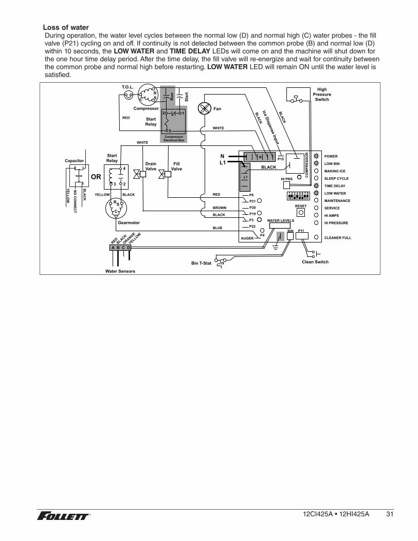
Loss of waterDuring operation, the water level cycles between the normal low (D) and normal high (C) water probes - the fill valve (P21) cycling on and off . If continuity is not detected between the common probe (B) and normal low (D) within 10 seconds, the LOW WATER and TIME DELAY LEDs will come on and the machine will shut down for the one hour time delay period . After the time delay, the fill valve will re-energize and wait for continuity between the common probe and normal high before restarting . LOW WATER LED will remain ON until the water level is satisfied .
5
2 1
Star
t
Run
Compressor
T.O.L.
MAINTENANCE
LOW WATER
TIME DELAY
SLEEP CYCLE
MAKING ICE
LOW BIN
POWER
SERVICE
HI AMPS
HI PRESSURE
CLEANER FULL
High Pressure Switch
R S C
Gearmotor
Start Relay
Start Relay
N L1
Fan
A B C D
Water Sensors
RESET
Fill Valve
Drain Valve
3
4
2
Bin T-Stat Clean Switch
P6
P21
P20
P19
P3
P22
P4 AUGER
WATER LEVELS
BIN P11
HI PRS L1
R S C
RED
WHITE
WHITE
BLACK
BROWN
BLUE
RED BLACK YELLOW
Compressor Electrical Box
CO
MPR
ESSO
R
1 2 3 4 5 6 7 8
BLACK
N P15 Ice Dispense Input
OR
Capacitor
BLA
CK
YELLOW
NO
CO
NN
ECT
12CI425A•12HI425A 31

High refrigerant pressureShould the refrigeration pressure rise above 425 psi, the high pressure switch contacts will open . The board sees the open circuit and the HIGH PRESSURE and TIME DELAY LEDs will come on, the machine shuts down . After the one hour time delay, the machine will attempt to restart . If the pressure has fallen below the reset point of 295 psi and the board see the contacts closed, the machine will resume normal operation . If the contacts are still open after the restart, the board will again go into HIGH PRESSURE and TIME DELAY, cycling until contact closure is seen .
5
2 1
Star
t
Run
Compressor
T.O.L.
MAINTENANCE
LOW WATER
TIME DELAY
SLEEP CYCLE
MAKING ICE
LOW BIN
POWER
SERVICE
HI AMPS
HI PRESSURE
CLEANER FULL
High Pressure Switch
R S C
Gearmotor
Start Relay
Start Relay
N L1
Fan
A B C D
Water Sensors
RESET
Fill Valve
Drain Valve
3
4
2
Bin T-Stat Clean Switch
P6
P21
P20
P19
P3
P22
P4 AUGER
WATER LEVELS
BIN P11
HI PRS L1
R S C
RED
WHITE
WHITE
BLACK
BROWN
BLUE
RED BLACK YELLOW
Compressor Electrical Box
CO
MPR
ESSO
R
1 2 3 4 5 6 7 8
BLACK
N P15 Ice Dispense Input
OR
Capacitor
BLA
CK
YELLOW
NO
CO
NN
ECT
32 12CI425A•12HI425A
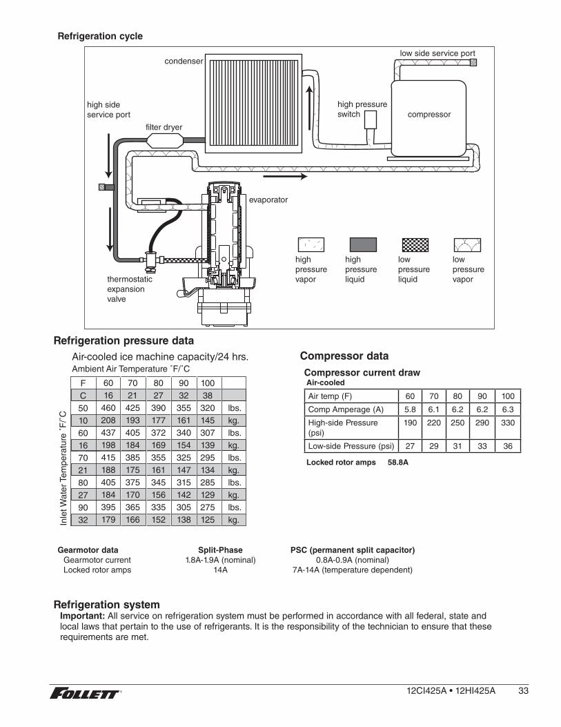
Refrigeration cycle
high side service port
filter dryer
condenserlow side service port
high pressure switch compressor
evaporator
thermostatic expansion valve
high pressure vapor
high pressure liquid
low pressure vapor
low pressure liquid
Refrigeration pressure data
Ambient Air Temperature ˚F/˚C
Inle
t Wat
er T
empe
ratu
re ˚
F/˚
C
FC50106016702180279032
6016
460208437198415188405184395179
7021425193405184385175375170365166
8027390177372169355161345156335152
9032355161340154325147315142305138
10038320145307139295134285129275125
lbs .kg .lbs .kg .lbs .kg .lbs .kg .lbs .kg .
Air-cooled ice machine capacity/24 hrs . Compressor dataCompressor current drawAir-cooled
Air temp (F) 60 70 80 90 100
Comp Amperage (A) 5 .8 6 .1 6 .2 6 .2 6 .3
High-side Pressure (psi)
190 220 250 290 330
Low-side Pressure (psi) 27 29 31 33 36
Locked rotor amps 58.8A
Gearmotor data Split-Phase PSC (permanent split capacitor)Gearmotor current 1 .8A-1 .9A (nominal) 0 .8A-0 .9A (nominal)Locked rotor amps 14A 7A-14A (temperature dependent)
Refrigeration systemImportant: All service on refrigeration system must be performed in accordance with all federal, state and local laws that pertain to the use of refrigerants . It is the responsibility of the technician to ensure that these requirements are met .
12CI425A•12HI425A 33

R425 ice machine charge specifications
Model Charge Refrigerant type
12CI425A, 12HI425A (air-cooled) 15 oz R404A
CAUTION! § Recharging of unit at other than factory specifications will void ice machine warranty .
Refrigerant replacement requirements1. Non-contaminated refrigerant removed from any Follett refrigeration system can be recycled and returned
to the same system after completing repairs . Recycled refrigerant must be stored in a clean, approved storage container . If additional refrigerant is required, virgin or reclaimed refrigerant that meets ARI standard 700-88 must be used .
2. In the event of system contamination (for example, a compressor burn out, refrigerant leak, presence of non-condensibles or moisture), the system must be repaired, evacuated and recharged using virgin or reclaimed refrigerant that meets ARI standard 700-88 .
3. Follett Corporation does not approve of recovered refrigerants . Improper refrigeration servicing procedures will void the factory warranty .
Evacuation Evacuate the system to a level of 500 microns . When the 500 micron level is reached, close valves and both manifold and shut down the vacuum pump . Allow the system to sit for approximately 20 minutes . During this period the system pressure should not rise . If the system pressure rises and stabilizes there is moisture in the system and further evacuation is needed . If the pressure continues to rise check the system for leaks .
Ice capacity test
Ice machine production capacity can only be determined by weighing ice produced in a specific time period .
1. Remove top panel and hopper lid of unit .2. Weigh and record weight of container used to catch ice .3. Run ice machine for at least 15 minutes .4. Catch ice for 15 or 20 minutes .5. Weigh harvested ice and record total weight .6. Subtract weight of container from total weight .7. Convert fractions of pounds to decimal equivalents (Ex . 6 lbs 8 oz = 6 .5 lbs) .8. Calculate production using following formula:
1440 min . x wt . of ice produced = Production capacity/24 hr . period Total test time in minutes
9. Calculated amount per 24 hours should be checked against rated capacity for same ambient and water temperatures in Ice Production Table (see page 31) .
34 12CI425A•12HI425A

Dispenser troubleshooting
CAUTION! § Disconnect power to unit before putting hands or arms in storage area or attempting any repair or service to equipment .
Before calling for service1. Check that no ice is in the dispenser bin area .2. Check that congealed ice is not causing a jam3. Check that all switches and circuit breakers are on4. Check that all drains are clear .5. Check water is supplied .
Lever model troubleshooting guideProblem Indicators Corrective Action
Does not dispense ice . 1 . Power switch off or faulty .
2 . Faulty dispense switch .
3 . Wheel motor malfunction .
1 . Check switch – turn on or replace if faulty .
2 . Replace switch .
3 . Check motor and replace
Dispense wheel rotates continuously .
Dispense switch contacts are burned out .
Replace dispense switch .
Ice machine runs continuously . Faulty or incorrectly positioned bin stat .
Check for proper positioning . If stat does not open when ice is placed on capillary tube, replace stat .
Does not dispense water . 1 . Faulty water solenoid valve .
2 . Faulty dispense switch .
3 . Power switch off or faulty .
1 . Replace water solenoid valve .
2 . Replace dispense switch .
3 . Check switch - turn on or replace if faulty .
SensorSAFE model troubleshooting guide
Problem Action
SensorSAFE Board LED Status
Corrective ActionPWR CLNICE/WTR
Does not dispense ice and/or water .
Check LEDs on the SensorSAFE control board .
OFF OFF OFF Check circuit breakers and power switch . Restore power or replace defective switch .
ON ON OFF Press clean switch on lower left side of electrical enclosure to return board to normal operation .
Place cup under drop zone (in front of lens)
ON OFF OFF Troubleshoot appropriate lens/sensor and replace if required (see lens/sensor troubleshooting) .
ON OFF ON Verify power on appropriate output terminal (WTR or WM) on control board and replace board if required . If board tests okay, troubleshoot appropriate dispenser component .
Dispenses ice and/or water continuously .
Check LEDs on control board .
ON OFF ON Troubleshoot appropriate lens/sensor and replace if required (see lens/sensor troubleshooting) .
ON OFF OFF If there is power on any output terminal 9WTR or WM) on control board, replace board .
12CI425A•12HI425A 35
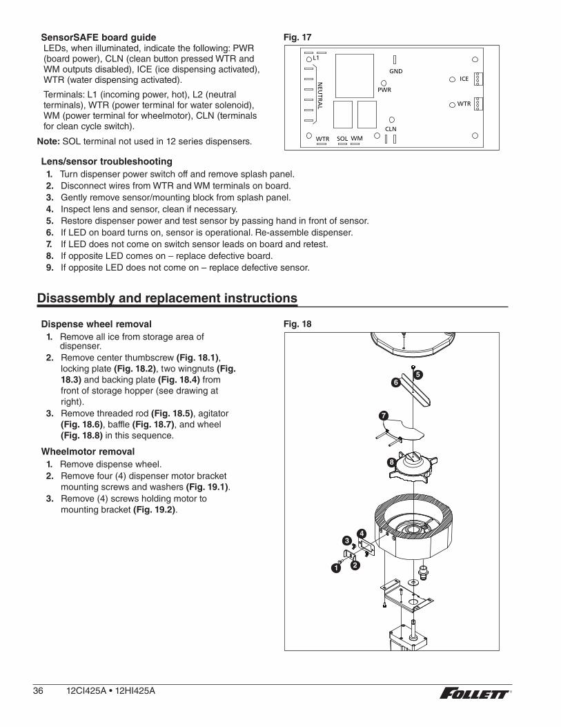
SensorSAFE board guideLEDs, when illuminated, indicate the following: PWR (board power), CLN (clean button pressed WTR and WM outputs disabled), ICE (ice dispensing activated), WTR (water dispensing activated) .
Terminals: L1 (incoming power, hot), L2 (neutral terminals), WTR (power terminal for water solenoid), WM (power terminal for wheelmotor), CLN (terminals for clean cycle switch) .
Note: SOL terminal not used in 12 series dispensers .
Fig. 17
SOLWTR
NEU
TRA
L
CLN
WM
PWR
WTR
L1
GNDICE
Lens/sensor troubleshooting1. Turn dispenser power switch off and remove splash panel .2. Disconnect wires from WTR and WM terminals on board .3. Gently remove sensor/mounting block from splash panel .4. Inspect lens and sensor, clean if necessary .5. Restore dispenser power and test sensor by passing hand in front of sensor .6. If LED on board turns on, sensor is operational . Re-assemble dispenser .7. If LED does not come on switch sensor leads on board and retest .8. If opposite LED comes on – replace defective board .9. If opposite LED does not come on – replace defective sensor .
Disassembly and replacement instructions
Dispense wheel removal 1. Remove all ice from storage area of
dispenser .2. Remove center thumbscrew (Fig. 18.1),
locking plate (Fig. 18.2), two wingnuts (Fig. 18.3) and backing plate (Fig. 18.4) from front of storage hopper (see drawing at right) .
3. Remove threaded rod (Fig. 18.5), agitator (Fig. 18.6), baffle (Fig. 18.7), and wheel (Fig. 18.8) in this sequence .
Wheelmotor removal1. Remove dispense wheel .2. Remove four (4) dispenser motor bracket
mounting screws and washers (Fig. 19.1) .3. Remove (4) screws holding motor to
mounting bracket (Fig. 19.2) .
Fig. 18
7
516
43
211
8
36 12CI425A•12HI425A
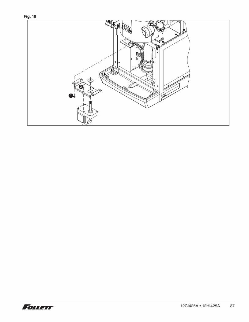
Fig. 19
1
2
12CI425A•12HI425A 37
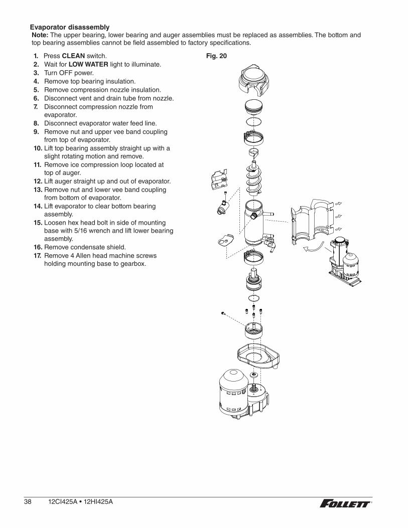
Evaporator disassemblyNote: The upper bearing, lower bearing and auger assemblies must be replaced as assemblies . The bottom and top bearing assemblies cannot be field assembled to factory specifications .
1. Press CLEAN switch .2. Wait for LOW WATER light to illuminate .3. Turn OFF power .4. Remove top bearing insulation .5. Remove compression nozzle insulation .6. Disconnect vent and drain tube from nozzle .7. Disconnect compression nozzle from
evaporator .8. Disconnect evaporator water feed line . 9. Remove nut and upper vee band coupling
from top of evaporator .10. Lift top bearing assembly straight up with a
slight rotating motion and remove .11. Remove ice compression loop located at
top of auger .12. Lift auger straight up and out of evaporator .13. Remove nut and lower vee band coupling
from bottom of evaporator .14. Lift evaporator to clear bottom bearing
assembly .15. Loosen hex head bolt in side of mounting
base with 5/16 wrench and lift lower bearing assembly .
16. Remove condensate shield .17. Remove 4 Allen head machine screws
holding mounting base to gearbox .
Fig. 20
38 12CI425A•12HI425A

Evaporator reassembly1. Clean gearmotor boss, output shaft and
shaft well .2. Install drain pan and evaporator mounting
base . 3. Fill gearmotor shaft well with food grade
grease (Fig. 21) .4. Install condensate shield and seat against
gearmotor boss .5. Install bearing O ring in groove in
evaporator mounting base .
Fig. 21
Apply grease in well
Evaporator drain pan and mounting base not shown for clarity.
6. While maintaining firm downward pressure on bottom bearing assembly, tighten hex head bolt with a 5/16 wrench .
7. Position evaporator over lower bearing assembly and align grooves with pins in bearing assembly .
8. Install vee band clamp and nut to 70 in/lb . (Fig. 22) .Note: Clamp must be oriented as shown
in order for the insulation to be placed properly .
9. Place auger in center of evaporator and rotate to mate with drive pin .
10. Install ice compression loop, orienting loop . 11. Install upper bearing and seal assembly,
rotating bearing to slip pin into auger slot . 12. Install upper vee band clamp and nut to 70
in/lb .13. Install compression nozzle and tubing .14. Secure ice transport tube with clamp
(Fig. 23.1) .
Note: Clamp must be oriented as shown in order for the insulation to be placed properly .
15. Install compression nozzle insulation (Fig. 23.2) .
16. Install vent and drain tube (Fig. 23.3) .17. Install top bearing insulation (Fig. 23.4) .
Gearmotor replacement1. Disassemble evaporator .2. Disconnect the wire connectors . 3. Remove 4 screws holding gearmotor
mounting plate to base of ice machine and lift gearbox and motor clear of ice machine .
4. Remove machine screws holding mounting plate to motor .
5. Install new motor in reverse order .
Fig. 22
Fig. 23
4
3
3
1
2
12CI425A•12HI425A 39
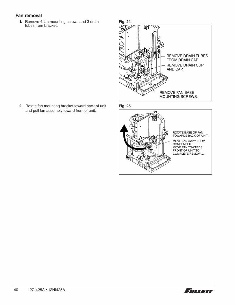
Fan removal1. Remove 4 fan mounting screws and 3 drain
tubes from bracket .Fig. 24
REMOVE DRAIN TUBESFROM DRAIN CAP.REMOVE DRAIN CUPAND CAP.
REMOVE FAN BASEMOUNTING SCREWS.
2. Rotate fan mounting bracket toward back of unit and pull fan assembly toward front of unit .
Fig. 25
ROTATE BASE OF FANTOWARDS BACK OF UNIT.
MOVE FAN AWAY FROMCONDENSER.MOVE FAN TOWARDSFRONT OF UNIT TOCOMPLETE REMOVAL.
40 12CI425A•12HI425A

Thermostat and ice transport tube replacement
.25
ice tube gasket
ice tube retainer
3" (76 mm)
0.50 TYP
2" (51 mm)
capillary tube
bracket
Thermostat: hand bend cap tube end as shown
Ice transport tube: tube may extend a maximumof 1/4" (6 mm) into ice bin
Ice transport tube replacement1. Refer to Fig. 23 . .
12CI425A•12HI425A 41
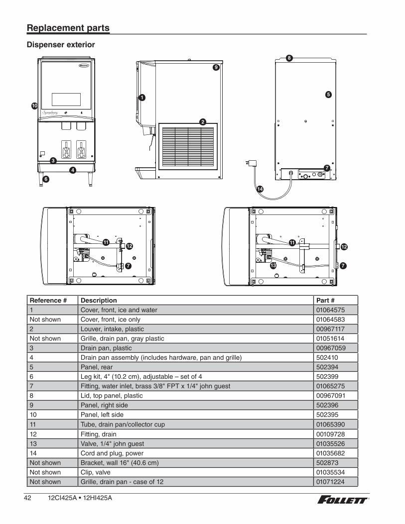
Replacement parts
Dispenser exterior
10
9
2
1
7
14
5
8
13
3
4
16
11 11
7
12
7
12
Reference # Description Part #1 Cover, front, ice and water 01064575Not shown Cover, front, ice only 010645832 Louver, intake, plastic 00967117Not shown Grille, drain pan, gray plastic 010516143 Drain pan, plastic 009670594 Drain pan assembly (includes hardware, pan and grille) 5024105 Panel, rear 5023946 Leg kit, 4" (10 .2 cm), adjustable – set of 4 5023997 Fitting, water inlet, brass 3/8" FPT x 1/4" john guest 010652758 Lid, top panel, plastic 009670919 Panel, right side 50239610 Panel, left side 502395
11 Tube, drain pan/collector cup 01065390
12 Fitting, drain 0010972813 Valve, 1/4" john guest 0103552614 Cord and plug, power 01035682Not shown Bracket, wall 16" (40 .6 cm) 502873Not shown Clip, valve 01035534Not shown Grille, drain pan - case of 12 01071224
42 12CI425A•12HI425A

Wheelmotor and drive system
12
13
4
5
2
3
14
8
6
1
9
3
6
7
5
2
11
15
10
Reference # Description Part #1 Motor, wheel, long shaft (includes gear motor shield) 5025802 Baffle, ice (securing hardware, part# 00167973, included) 5024143 Wheel with Agion, agitator 5023874 Rod, threaded (includes knurled nut) 5023905 Agitator, rotating 502386See page 41 Bracket, capillary tube 502406See page 41 Retainer, ice tube 00977314See page 41 Gasket, ice tube 009773226 Assembly, hopper with Agion (includes drain fitting) 5024137 Reservoir assembly 010646828 Fitting, hopper drain, 3/4 MPT, 3/4" barb fitting 2070959 Switch, interlock 50241610 Support plate, motor 50242311 Cover, electrical box 50240812 Screws, 10-32 x 1/2 (6 needed) 20102213 Hopper lid with hopper lid safety switch actuation 00951541Not shown Hopper lid, dispenser top cover, safety switch actuation (Before SN# B72959) 20780914 Hardware, baffle securing 0016797315 Shield, gear motor 502537
12CI425A•12HI425A 43
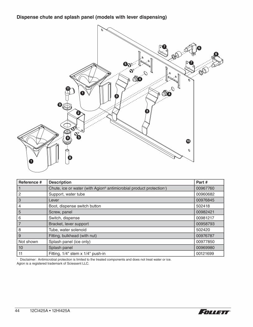
Dispense chute and splash panel (models with lever dispensing)
1
7 6
7
6
5
4
4
10
3
3
9
5
8
9
1
2
11
Reference # Description Part #1 Chute, ice or water (with Agion® antimicrobial product protection1) 009677602 Support, water tube 009606823 Lever 009768454 Boot, dispense switch button 5024185 Screw, panel 009824216 Switch, dispense 009812177 Bracket, lever support 009587938 Tube, water solenoid 5024209 Fitting, bulkhead (with nut) 00976787Not shown Splash panel (ice only) 0097785010 Splash panel 0096998011 Fitting, 1/4" stem x 1/4" push-in 00121699
1 Disclaimer: Antimicrobial protection is limited to the treated components and does not treat water or ice .Agion is a registered trademark of Sciessent LLC .
44 12CI425A•12HI425A

Dispense chute and splash panel (models with SensorSAFE infrared dispensing)
7
8
8
2
21
1 6
5 4
3
5
10
Reference # Description Part #1 Chute, ice or water (with Agion) 009677602 Sensor (includes lens and Ty-rap*) 001229783 Support, water tube 009606824 Screw, panel 009824215 Fitting, bulkhead (with nut) 009767876 Tube, water solenoid 502420Not shown Splash panel, without drain pan (includes 2 Ty-raps and 2 lenses) 009813577 Splash panel, (includes 2 Ty-raps and 2 lenses) 009813328 Lens, sensor (each) 502690Not shown Splash panel, ice only (includes 1 Ty-raps and 1 lens) 009813409 Solenoid, assembly (includes fittings, screws) 0098120910 Fitting, 1/4" stem x 1/4" push-in 00121699
* Ty-rap is a registered trademark of Thomas & Betts International, Inc .
12CI425A•12HI425A 45
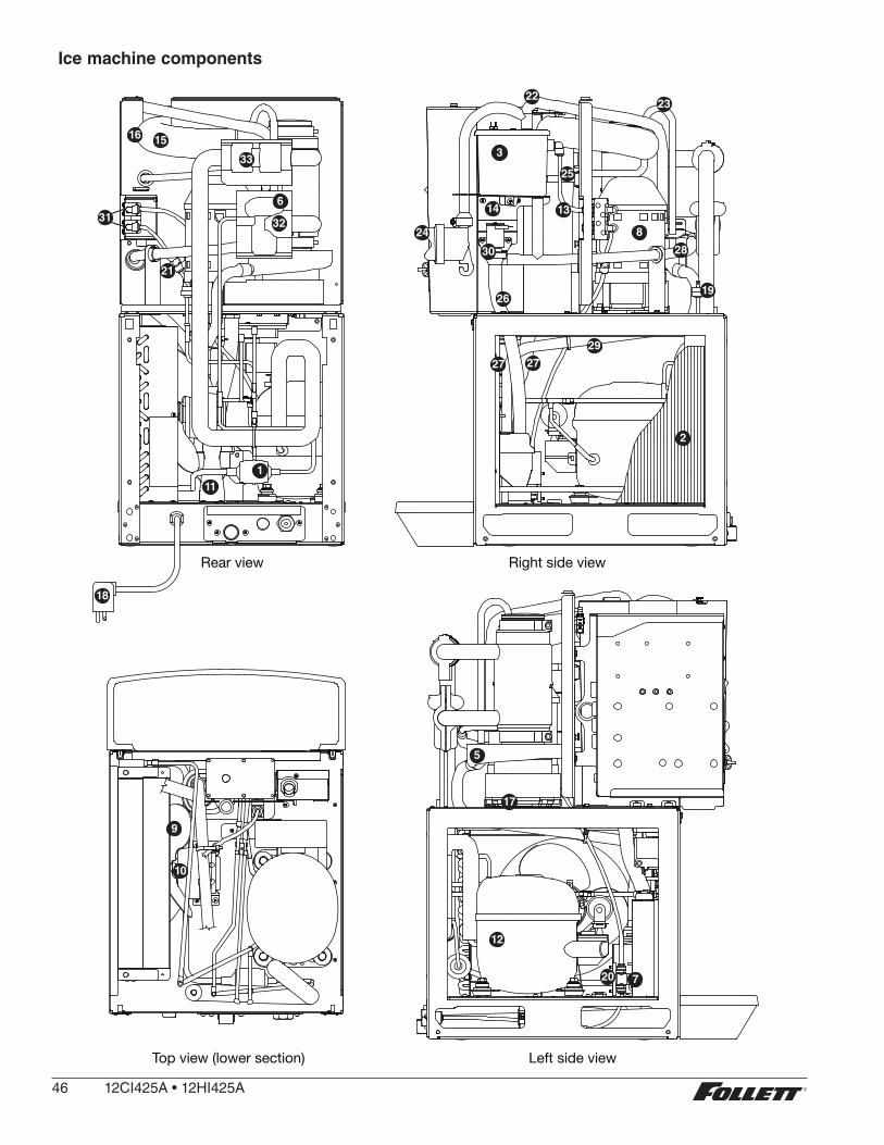
Ice machine components
Rear view Right side view
Left side viewTop view (lower section)
1
25
14
3
24
6
11
23
18
13
8
28
19
30
26
27
29
2
22
9
10
5
17
12
720
16 15
31
21
27
32
33
46 12CI425A•12HI425A
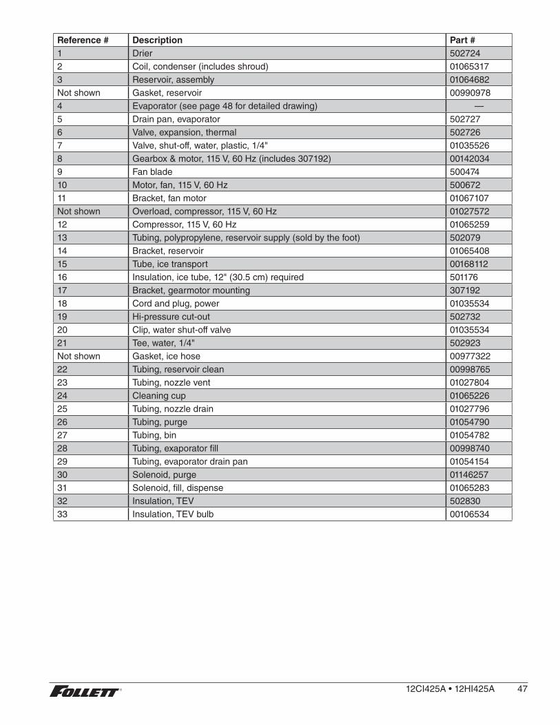
Reference # Description Part #1 Drier 5027242 Coil, condenser (includes shroud) 010653173 Reservoir, assembly 01064682Not shown Gasket, reservoir 009909784 Evaporator (see page 48 for detailed drawing) —5 Drain pan, evaporator 5027276 Valve, expansion, thermal 5027267 Valve, shut-off, water, plastic, 1/4" 010355268 Gearbox & motor, 115 V, 60 Hz (includes 307192) 001420349 Fan blade 50047410 Motor, fan, 115 V, 60 Hz 50067211 Bracket, fan motor 01067107Not shown Overload, compressor, 115 V, 60 Hz 0102757212 Compressor, 115 V, 60 Hz 0106525913 Tubing, polypropylene, reservoir supply (sold by the foot) 50207914 Bracket, reservoir 0106540815 Tube, ice transport 0016811216 Insulation, ice tube, 12" (30 .5 cm) required 50117617 Bracket, gearmotor mounting 30719218 Cord and plug, power 0103553419 Hi-pressure cut-out 50273220 Clip, water shut-off valve 0103553421 Tee, water, 1/4" 502923Not shown Gasket, ice hose 0097732222 Tubing, reservoir clean 0099876523 Tubing, nozzle vent 0102780424 Cleaning cup 0106522625 Tubing, nozzle drain 0102779626 Tubing, purge 0105479027 Tubing, bin 0105478228 Tubing, exaporator fill 0099874029 Tubing, evaporator drain pan 0105415430 Solenoid, purge 0114625731 Solenoid, fill, dispense 0106528332 Insulation, TEV 50283033 Insulation, TEV bulb 00106534
12CI425A•12HI425A 47

Electrical components
4 3
5
1
6
7
2
Reference # Description Part #
1 Board, control circuit, 115 V, 60 Hz 01064708
2 Switch, clean 00117036
3 Switch, rocker, power 502209
4 Switch, rocker, bin signal 502209
5 Switch, cleaning, SensorSAFE models 502409
6 Control board, SensorSAFE models 502242
7 Bin thermostat 500514
48 12CI425A•12HI425A
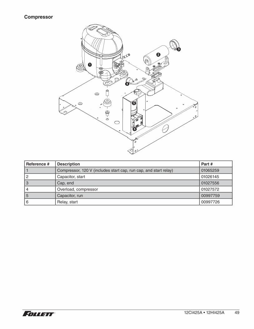
Compressor
1
2
4
3
5
6
Reference # Description Part #
1 Compressor, 120 V (includes start cap, run cap, and start relay) 01065259
2 Capacitor, start 01026145
3 Cap, end 01027556
4 Overload, compressor 01027572
5 Capacitor, run 00997759
6 Relay, start 00997726
12CI425A•12HI425A 49
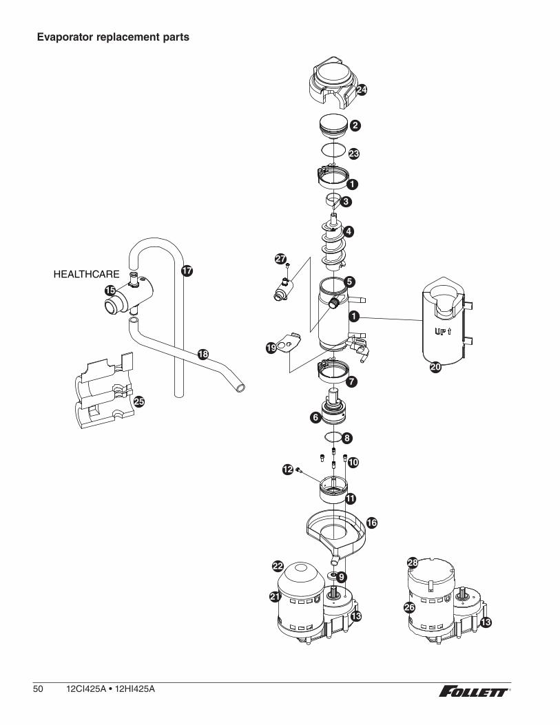
Evaporator replacement parts
HEALTHCARE
15
17
18
24
1
3
4
5
20
19
7
6
8
10
11
12
16
922
21
13
1
23
2
25
26
13
27
28
50 12CI425A•12HI425A

Reference # Description Part #
1 Coupling, vee band, includes nut 502735
2 Bearing assembly, top 502736
3 Loop, ice compression, beveled 502110
4 Auger (see below for Flaker-specific components) 502737
5 Evaporator (includes insulation jacket, and top bearing insulation) 01064658
6 O ring, bearing housing 500496
7 Bearing assembly, bottom (includes O rings and condensate shield) 502738
8 O ring, mounting base 501063
9 Shield, condensate 500744
10 Screw, Allen 1/4 20 x 1/2 (set of 4) 501080
11 Mounting base, evap . (includes 501063) 502733
12 Bolt, mounting base 502227
13 Gearbox & motor (includes mounting base) 00142034
Not shown Mounting base, gearbox 01067693
15 Compression nozzle, with single drain 01064674
16 Drain pan, evaporator 00181990
17 Tube, compression nozzle vent 01027804
18 Tube, compression nozzle, single drain 01027416
Not shown Grease, Mobil FM222, 14 oz 501111
19 Bracket, vent hoses 01007087
20 Insulation jacket, evaporator 01049592
21 Relay, gearmotor 00142042
22 Cover, black plastic 01012228
23 O ring, top bearing 01064963
24 Insulation, top bearing 01049600
25 Insulation, compression nozzle, single drain 01049584
26 16 µF Capacitor (for PSC motor only) 01103142
27 Screw, compression nozzle 00956250
28 Cover, aluminum 01106376
Not shown O-ring, compression nozzle 00988097
12CI425A•12HI425A 51
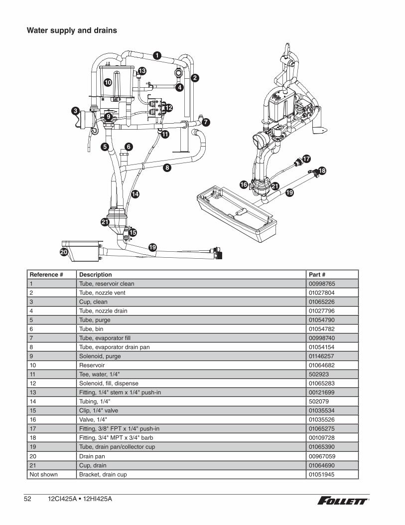
Water supply and drains
1
2
4
13
10
3 129
5 6
11
7
14
15
21
2019
19
18
17
16 21
8
Reference # Description Part #
1 Tube, reservoir clean 00998765
2 Tube, nozzle vent 01027804
3 Cup, clean 01065226
4 Tube, nozzle drain 01027796
5 Tube, purge 01054790
6 Tube, bin 01054782
7 Tube, evaporator fill 00998740
8 Tube, evaporator drain pan 01054154
9 Solenoid, purge 01146257
10 Reservoir 01064682
11 Tee, water, 1/4" 502923
12 Solenoid, fill, dispense 01065283
13 Fitting, 1/4" stem x 1/4" push-in 00121699
14 Tubing, 1/4" 502079
15 Clip, 1/4" valve 01035534
16 Valve, 1/4" 01035526
17 Fitting, 3/8" FPT x 1/4" push-in 01065275
18 Fitting, 3/4" MPT x 3/4" barb 00109728
19 Tube, drain pan/collector cup 01065390
20 Drain pan 00967059
21 Cup, drain 01064690
Not shown Bracket, drain cup 01051945
52 12CI425A•12HI425A

Water treatment accessories for Symphony Plus ice and water dispensers
Reference # Description Part #
Standard capacity filter system
Not shown Follett QC4-FL4S water filter system (includes FL4S primary cartridge and head, coarse pre-filter and head, pressure gauge, flushing valve; assembled and installed on mounting bracket), one per ice machine
00130229
Not shown Follett FL4S primary replacement cartridge 00130245
Not shown Water filter cartridge – primary, carton of 6 00954297
Not shown Everpure coarse pre-filter cartridge 00130211
Not shown Water pre-filter cartridge – pre-filter, carton of 12 00954305
High capacity filter system
Not shown High capacity water filter system (one per ice machine) 00978957
Not shown High capacity water filter cartridge – primary, single 00978965
Not shown High capacity water filter cartridge – primary, carton of 6 00978973
Not shown Water pre-filter cartridge – pre-filter, single 00130211
Not shown Water pre-filter cartridge – pre-filter, carton of 12 00954305
Carbonless high capacity filter system
Not shown Carbonless high capacity water filter system (one per ice machine) – Horizon™ and MaestroPlus series ice machines
01050442
Not shown Carbonless high capacity water filter cartridge – primary, single 01050426
Not shown Carbonless high capacity water filter cartridge – primary, carton of 6 01050434
Not shown Water pre-filter cartridge – pre-filter, single 00130211
Not shown Water pre-filter cartridge – pre-filter, carton of 12 00954305
Other filtration
Not shown Claris hardness removal filtration system 00986059
Not shown Replacement filter for Claris system 00985127
Not shown Reverse osmosis system, 200 gallons per day 00986034
Not shown Replacement reverse osmosis cartridge 00985085
Not shown Replacement reverse osmosis pre-filter 00985077
Not shown Cleaning plug for reverse osmosis system 00985119
Not shown Cleaning cartridge for reverse osmosis system 00985101
Water pressure
Not shown Water pressure regulator (25 psi) 501781
Cleaning/Sanitizing
Not shown SafeCLEAN ice machine cleaner, carton of 24 x 7 oz packets 00132001
Not shown Sponge, sanitary, each 00131524
Not shown IMS-II or IMS-III sanitizing concentrate
16 oz bottle 00979674
Case of 12 x 16 oz bottles 01038652
12CI425A•12HI425A 53

54 12CI425A•12HI425A

12CI425A•12HI425A 55

01033653R04 © Follet LLC 2/17
801 Church Lane • Easton, PA 18040, USAToll free (877) 612-5086 • +1 (610) 252-7301www.follettice.com
SafeCLEAN, SensorSAFE, Maestro Plus, Symphony Plus, Quiet Night and Sani-Sponge are trademarks of Follett LLC.Follett and RIDE are registered trademarks of Follett LLC, registered in US.