sync™, knight®/knight xl®/armor/wall mount/walllochinvar.com/_linefiles/protonode startup guide...
TRANSCRIPT

Document Revision: 12.C Auto Selector
Template Revision: 49
ProtoNode FPC-N34 and ProtoNode FPC-N35 Startup Guide
For Interfacing Lochinvar Products: SYNC™, Knight®/Knight XL®/Armor/Wall Mount/Wall Hung, Crest®, Copper-Fin II®, Power Fin, Knight FTXL
To Building Automation Systems: BACnet MS/TP, BACnet/IP, Modbus TCP/IP, Metasys N2
and LonWorks
APPLICABILITY & EFFECTIVITY
Explains ProtoNode FPC-N34 and FPC-N35 hardware and how to install it.
The instructions are effective for the above as of September 2015

INS70085/100161100/2000007506 Rev H Lochinvar’s ProtoNode Startup Guide
Page 2 of 49
Technical Support:
Thank you for purchasing the ProtoNode for Lochinvar Boilers.
Please call Lochinvar for Technical support of the ProtoNode product.
FieldServer does not provide direct support. If Lochinvar needs to escalate the concern, they will contact
FieldServer for assistance.
Support Contact Information:
Lochinvar, LLC
300 Maddox Simpson Pkwy.
Lebanon, TN 37090
Lochinvar Service:
1-800-722-2101
Email: [email protected]
Website: www.lochinvar.com

Page 3 of 49
A Quick Start Guide
1. Record the information about the unit. (Section 2.1)
2. Set the device’s Modbus RTU serial settings (i.e. baud rate, parity, stop bits) and Modbus Node-ID
for each of the devices that will be connected to ProtoNode FPC-N34 or FPC-N35. (Section 2.2)
3. Select a stored configuration and set field protocol MAC address/Node-ID/Device Instance, and baud
rate. (Section 2.3)
4. Connect ProtoNode’s 6 pin RS-485 connector to the Modbus RS-485 network that is connected to
each of the devices. (Section 3.2)
5. Connect ProtoNode FPC-N34’s 3 pin RS-485 port to the Field Protocol cabling, (Section 3.3)or connect ProtoNode FPC-N35’s 2 pin LonWorks port to the Field Protocol cabling. (Section 3.4)
6. Connect Power to ProtoNode’s 6 pin connector. (Section 3.5)
7. BACnet/IP or Modbus TCP/IP (FPC-N34): Use the ProtoNode’s embedded tool which is accessed
with a browser, referred to in this manual as the Web Configurator, to change the IP address. No
changes to the configuration file are necessary. (Section 4)
8. LonWorks (FPC-N35): The ProtoNode must be commissioned on the LonWorks Network. This
needs to be done by the LonWorks administrator using a LonWorks Commissioning tool. (Section 6)
INS70085/100161100/2000007506 Rev H Lochinvar’s ProtoNode Startup Guide

Page 4 of 49
Certifications
BTL MARK – BACNET TESTING LABORATORY
LONMARK CERTIFICATION
The BTL Mark on ProtoNode RER is a symbol that indicates that a product has
passed a series of rigorous tests conducted by an independent laboratory
which verifies that the product correctly implements the BACnet features
claimed in the listing. The mark is a symbol of a high-quality BACnet product.
Go to http://www.BACnetInternational.net/btl/ for more information about the BACnet Testing Laboratory. Click here for BACnet PIC Statement
.
LonMark International is the recognized authority for certification, education,
and promotion of interoperability standards for the benefit of manufacturers,
integrators and end users. LonMark International has developed extensive
product certification standards and tests to provide the integrator and user with
confidence that products from multiple manufacturers utilizing LonMark
devices work together. FieldServer Technologies has more LonMark Certified
gateways than any other gateway manufacturer, including the ProtoCessor,
ProtoCarrier and ProtoNode for OEM applications and the full featured,
configurable gateways.
INS70085/100161100/2000007506 Rev H Lochinvar’s ProtoNode Startup Guide

Page 5 of 49
TABLE OF CONTENTS
1 Introduction................................................................................................................................................. 7 1.1 ProtoNode Gateway ................................................................................................................................... 7
2 BACnet/LonWorks Setup for ProtoCessor ProtoNode FPC-N34/FPC-N35 ...................................... 8 2.1 Record Identification Data ......................................................................................................................... 8 2.2 Configuring Device Communications ....................................................................................................... 8
2.2.1 Set Modbus COM setting on all of the devices connected to the ProtoNode .............................. 8 2.2.2 Set Modbus RTU Node-ID for each of the devices attached to the ProtoNode .......................... 9
2.3 BMS Network Settings: Selecting Stored Configurations, Setting the Mac Address, Device
Instance, and Baud Rate ..................................................................................................................................... 10 2.3.1 Selecting Configuration Files for Devices: “S” bank DIP Switches S0 – S3 ............................... 10
2.3.1.1 BACnet MS/TP and BACnet/IP DIP Switch Settings ............................................................ 10
2.3.1.2 LonWorks DIP Switch Settings ................................................................................................. 11
2.3.2 BACnet MS/TP (FPC-N34): Setting the MAC Address for BMS Network .................................. 11 2.3.3 BACnet MS/TP and BACnet/IP (FPC-N34): Setting the Device Instance .................................. 12
2.3.3.1 BACnet MS/TP or BACnet/IP: Assigning Specific Device Instances ................................ 12
2.3.4 Metasys N2 or Modbus TCP/IP (FPC-N34): Setting the Node-ID ............................................... 12 2.3.5 BACnet MS/TP (FPC-N34): Setting the Serial Baud Rate for BMS Network ............................. 13
2.3.5.1 Baud Rate DIP Switch Selection .............................................................................................. 13
3 Interfacing ProtoNode to Devices ......................................................................................................... 14 3.1 ProtoNode FPC-N34 and FPC-N35 Showing Connection Ports ....................................................... 14 3.2 Device Connections to ProtoNode ......................................................................................................... 15
3.2.1 End of Line Termination Switch for the Modbus RS-485 Device Network ................................. 16 3.2.2 Lochinvar’s Armor, SYNC/Armor X2, Knight/Knight XL, Crest, Copper-Fin II and FTXL Low
Voltage Modbus RTU Connection Wiring to the ProtoNode: ..................................................................... 17 3.3 BACnet MS/TP or Metasys N2 (FPC-N34): Wiring Field Port to RS-485 BMS Network ............... 18 3.4 LonWorks (FPC-N35): Wiring Field Port to LonWorks Network ........................................................ 18 3.5 Power-Up ProtoNode ............................................................................................................................... 19
4 BACnet/IP and Modbus TCP/IP: Change the Protonode IP Address .............................................. 20 4.1 Connect the PC to ProtoNode via the Ethernet Port ........................................................................... 20 4.2 BACnet/IP and Modbus TCP/IP: Setting IP Address for Field Network ............................................ 21
5 BACnet MS/TP and BACnet/IP: Setting Node_Offset to Assign Specific Device Instances ..... 23
6 LonWorks (FPC-N35): Commissioning ProtoNode on a lonworks Network ................................. 24 6.1 Commissioning ProtoNode FPC-N35 on a LonWorks Network ......................................................... 24
6.1.1 Instructions to Download XIF File from ProtoNode FPC-N35 Using Browser ........................... 24
7 CAS BACnet Explorer for Validating ProtoNode in the Field ........................................................... 26 7.1 Downloading the CAS Explorer and Requesting an Activation Key .................................................. 26 7.2 CAS BACnet Setup ................................................................................................................................... 27
7.2.1 CAS BACnet MS/TP Setup................................................................................................................ 27 7.2.2 CAS BACnet BACnet/IP Setup ......................................................................................................... 27
Appendix A. Troubleshooting ....................................................................................................................... 28 Appendix A.1. Viewing Diagnostic information ................................................................................................. 28 Appendix A.2. Check Wiring and Settings ........................................................................................................ 29 Appendix A.3. Take Diagnostic Capture With the FieldServer Utilities......................................................... 29 Appendix A.4. BACnet: Setting Network_Number for more than one ProtoNode on Subnet ................... 32 Appendix A.5. LED Diagnostics for Modbus RTU Communications Between ProtoNode and Devices . 33 Appendix A.6. Passwords .................................................................................................................................... 33
Appendix B. Additional Features .................................................................................................................. 34
INS70085/100161100/2000007506 Rev H Lochinvar’s ProtoNode Startup Guide

Page 6 of 49
Appendix B.1. DIP switch settings to support Metasys N2 ............................................................................. 34
Appendix C. Vendor Information - Lochinvar ............................................................................................. 35 Appendix C.1. Sync Modbus RTU Mappings to BACnet MS/TP, BACnet/IP, Metasys N2 and LonWorks
................................................................................................................................................................................. 35 Appendix C.2. Knight Modbus RTU Mappings to BACnet MS/TP, BACnet/IP, Metasys N2 and
LonWorks ............................................................................................................................................................... 36 Appendix C.3. Crest Modbus RTU Mappings to BACnet MS/TP, BACnet/IP, Metasys N2 and LonWorks
................................................................................................................................................................................. 38 Appendix C.4. Copper-Fin II Modbus RTU Mappings to BACnet MS/TP, BACnet/IP, Metasys N2 and
LonWorks ............................................................................................................................................................... 40 Appendix C.5. Power Fin Modbus RTU Mappings to BACnet MS/TP, BACnet/IP, Metasys N2 and
LonWorks ............................................................................................................................................................... 41 Appendix C.6. Knight FTXL Modbus RTU Mappings to BACnet MS/TP, BACnet/IP, Metasys N2 and
LonWorks ............................................................................................................................................................... 43
Appendix D. “A” Bank DIP Switch Settings ................................................................................................ 45 Appendix D.1. “A” Bank DIP Switch Settings .................................................................................................... 45
Appendix E. Reference ................................................................................................................................... 48 Appendix E.1. Specifications ............................................................................................................................... 48
Appendix E.1.1. Compliance with UL Regulations ................................................................................... 48
Appendix F. Limited 2 Year Warranty .......................................................................................................... 49
LIST OF FIGURES
Figure 1: ProtoCessor Part Numbers ....................................................................................................................... 8 Figure 2: Modbus RTU COM Settings ..................................................................................................................... 8 Figure 3: Lochinvar’s Modbus COM board showing serial DIP Switches .......................................................... 8 Figure 4: S Bank DIP Switches ............................................................................................................................... 10 Figure 5: MAC Address DIP Switches ................................................................................................................... 11 Figure 6: Baud Rate DIP Switches ......................................................................................................................... 13 Figure 7: BMS Baud Rate ........................................................................................................................................ 13 Figure 8: ProtoNode BACnet FPC-N34 (upper) and ProtoNode FPC-N35 (lower) ........................................ 14 Figure 9: Power and RS-485 Connections ........................................................................................................... 15 Figure 10: Modbus RS-485 End-Of-Line Termination Switch on the ProtoNode N34 (left) and ................... 16 Figure 11: Low Voltage Modbus RTU Connection Wiring to the ProtoNode ................................................... 17 Figure 12: Connection from ProtoNode to RS-485 Field Network .................................................................... 18 Figure 13: RS-485 BMS Network EOL Switch ..................................................................................................... 18 Figure 14: LonWorks Terminal ................................................................................................................................ 18 Figure 15: Required current draw for the ProtoNode .......................................................................................... 19 Figure 16: Power Connections ................................................................................................................................ 19 Figure 17: Web Configuration Screen ................................................................................................................... 21 Figure 18: Changing IP Address via FST Web GUI ............................................................................................ 22 Figure 19: Web Configurator screen ...................................................................................................................... 23 Figure 20: LonWorks Service Pin Location ........................................................................................................... 24 Figure 21: Sample of Fserver.XIF File Being Generated .................................................................................... 25 Figure 22: Downloading the CAS Explorer ........................................................................................................... 26 Figure 23: Requesting CAS Activation Key .......................................................................................................... 26 Figure 24: Error messages screen ......................................................................................................................... 28 Figure 25: Ethernet Port Location........................................................................................................................... 29 Figure 26: Web Configurator showing setting the network number for BACnet/IP ......................................... 32 Figure 27: Diagnostic LEDs ..................................................................................................................................... 33 Figure 28: Specifications ......................................................................................................................................... 48
INS70085/100161100/2000007506 Rev H Lochinvar’s ProtoNode Startup Guide
Page 7 of 49
1 INTRODUCTION
1.1 ProtoNode Gateway
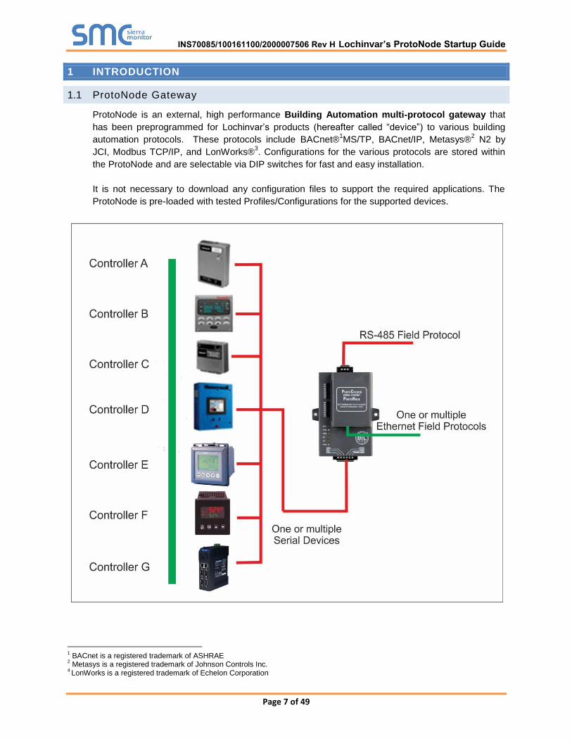
ProtoNode is an external, high performance Building Automation multi-protocol gateway that
has been preprogrammed for Lochinvar’s products (hereafter called “device”) to various building
automation protocols. These protocols include BACnet®1MS/TP, BACnet/IP, Metasys®
2 N2 by
JCI, Modbus TCP/IP, and LonWorks®3. Configurations for the various protocols are stored within
the ProtoNode and are selectable via DIP switches for fast and easy installation.
It is not necessary to download any configuration files to support the required applications. The
ProtoNode is pre-loaded with tested Profiles/Configurations for the supported devices.
1 BACnet is a registered trademark of ASHRAE
2 Metasys is a registered trademark of Johnson Controls Inc.
4 LonWorks is a registered trademark of Echelon Corporation
INS70085/100161100/2000007506 Rev H Lochinvar’s ProtoNode Startup Guide

Page 8 of 49
2 BACNET/LONWORKS SETUP FOR PROTOCESSOR PROTONODE FPC-N34/FPC-N35
2.1 Record Identif ication Data
Each ProtoNode has a unique part number located on the side or the back of the unit. This number
should be recorded, as it may be required for technical support. The numbers are as follows:
Model Part Number
ProtoNode FPC-N34 FPC-N34-0614
ProtoNode FPC-N35 FPC-N35-0615
Figure 1: ProtoCessor Part Numbers
FPC-N34 units have the following 3 ports: RS-485 + Ethernet + RS-485.
FPC-N35 units have the following 3 ports: LonWorks + Ethernet + RS-485
2.2 Configuring Device Communications
2.2.1 Set Modbus COM setting on all of the devices connected to the ProtoNode
All of the Serial devices connected to ProtoNode MUST have the same Baud Rate, Data Bits,
Stop Bits, and Parity settings.
Figure 2 specifies the device serial port settings required to communicate with the ProtoNode.
Serial Port Setting Device
Protocol Modbus RTU
Baud Rate 9600
Parity None
Data Bits 8
Stop Bits 2
Figure 2: Modbus RTU COM Settings
Figure 3: Lochinvar’s Modbus COM board showing serial DIP Switches
INS70085/100161100/2000007506 Rev H Lochinvar’s ProtoNode Startup Guide

Page 9 of 49
2.2.2 Set Modbus RTU Node-ID for each of the devices attached to the ProtoNode
Set the Modbus Node-ID for each of the devices attached to ProtoNode.
The Modbus Node-ID’s need to be uniquely assigned, starting with a value of 1 for the first
device.
Modbus Node-ID values for additional devices must be sequential (2, 3, 4, …).
INS70085/100161100/2000007506 Rev H Lochinvar’s ProtoNode Startup Guide
Page 10 of 49
2.3 BMS Network Settings: Selecting Stored Configurations, Setting the Mac
Address, Device Instance, and Baud Rate
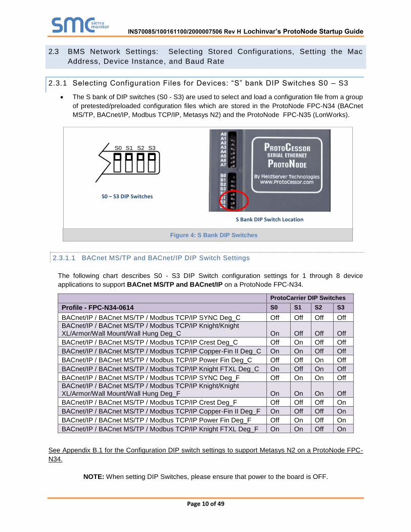
2.3.1 Selecting Configuration Files for Devices: “S” bank DIP Switches S0 – S3
The S bank of DIP switches (S0 - S3) are used to select and load a configuration file from a group
of pretested/preloaded configuration files which are stored in the ProtoNode FPC-N34 (BACnet
MS/TP, BACnet/IP, Modbus TCP/IP, Metasys N2) and the ProtoNode FPC-N35 (LonWorks).
2.3.1.1 BACnet MS/TP and BACnet/IP DIP Switch Settings
The following chart describes S0 - S3 DIP Switch configuration settings for 1 through 8 device
applications to support BACnet MS/TP and BACnet/IP on a ProtoNode FPC-N34.
ProtoCarrier DIP Switches
Profile - FPC-N34-0614 S0 S1 S2 S3
BACnet/IP / BACnet MS/TP / Modbus TCP/IP SYNC Deg_C Off Off Off Off
BACnet/IP / BACnet MS/TP / Modbus TCP/IP Knight/Knight XL/Armor/Wall Mount/Wall Hung Deg_C On Off Off Off
BACnet/IP / BACnet MS/TP / Modbus TCP/IP Crest Deg_C Off On Off Off
BACnet/IP / BACnet MS/TP / Modbus TCP/IP Copper-Fin II Deg_C On On Off Off
BACnet/IP / BACnet MS/TP / Modbus TCP/IP Power Fin Deg_C Off Off On Off
BACnet/IP / BACnet MS/TP / Modbus TCP/IP Knight FTXL Deg_C On Off On Off
BACnet/IP / BACnet MS/TP / Modbus TCP/IP SYNC Deg_F Off On On Off
BACnet/IP / BACnet MS/TP / Modbus TCP/IP Knight/Knight XL/Armor/Wall Mount/Wall Hung Deg_F On On On Off
BACnet/IP / BACnet MS/TP / Modbus TCP/IP Crest Deg_F Off Off Off On
BACnet/IP / BACnet MS/TP / Modbus TCP/IP Copper-Fin II Deg_F On Off Off On
BACnet/IP / BACnet MS/TP / Modbus TCP/IP Power Fin Deg_F Off On Off On
BACnet/IP / BACnet MS/TP / Modbus TCP/IP Knight FTXL Deg_F On On Off On
See Appendix B.1 for the Configuration DIP switch settings to support Metasys N2 on a ProtoNode FPC-
N34.
NOTE: When setting DIP Switches, please ensure that power to the board is OFF.
S0 S1 S2 S3
S0 – S3 DIP Switches
S Bank DIP Switch Location
Figure 4: S Bank DIP Switches
INS70085/100161100/2000007506 Rev H Lochinvar’s ProtoNode Startup Guide

Page 11 of 49
2.3.1.2 LonWorks DIP Switch Settings
The following chart describes the DIP switch settings to support LonWorks on a ProtoNode FPC-N35.
ProtoCarrier DIP Switches
Profile - FPC-N35-0615 S0 S1 S2 S3
LonWorks SYNC Off Off Off Off
LonWorks Knight/Knight XL/Armor/Wall Mount/Wall Hung
On Off Off Off
LonWorks Crest Off On Off Off
LonWorks Copper-Fin II On On Off Off
LonWorks Power Fin Off Off On Off
LonWorks Knight FTXL On Off On Off
NOTE: When setting DIP Switches, please ensure that power to the board is OFF.
2.3.2 BACnet MS/TP (FPC-N34): Setting the MAC Address for BMS Network
Only 1 MAC address is set for ProtoNode regardless of how many devices are connected to
ProtoNode.
Set the BACnet MS/TP MAC addresses of the ProtoNode to a value between 1 to 127 (MAC
Master Addresses); this is so that the BMS Front End can find the ProtoNode via BACnet
auto discovery.
Note: Never set a BACnet MS/TP MAC Address from 128 to 255. Addresses from 128 to
255 are Slave Addresses and can not be discovered by BMS Front Ends that support auto
discovery of BACnet MS/TP devices.
Set DIP switches A0 – A7 to assign MAC Address for BACnet MS/TP for the ProtoNode
FPC-N34.
Please refer to Appendix D.1 for the complete range of MAC Addresses and DIP switch
settings.
NOTE: When setting DIP Switches, please ensure that power to the board is OFF.
Figure 5: MAC Address DIP Switches
INS70085/100161100/2000007506 Rev H Lochinvar’s ProtoNode Startup Guide

Page 12 of 49
2.3.3 BACnet MS/TP and BACnet/IP (FPC-N34): Setting the Device Instance
The A Bank of DIP switches are used for two purposes:
o For BACnet MS/TP, they are used to set the BACnet MS/TP MAC address. (Section
2.3.2)
o For both BACnet MS/TP and BACnet/IP, they are also used to determine the BACnet
Device Instance values.
The BACnet Device Instance can range from 1 to 4,194,303.
The BACnet device instances will be calculated by taking the Node_Offset (default is 50,000)
found in Web Configurator (Section 2.3.2.1) and adding it to the value of the A Bank DIP
switches. When more than one device is connected to the ProtoNode, the subsequent BACnet
Device Instance values will be sequential from the first/previous device.
For example:
Given that: Device Instance = Node_Offset + A Bank DIP switch value
o Default Node_Offset value = 50,000
o A Bank DIP switch value = 11
Then the Device Instance values for the devices are:
o Device 1 Instance = 50,011
o Device 2 Instance will then be 50,011(Device Instance 1) +1 = 50,012
o Device 3 Instance will then be 50,012 (previous Device Instance) +1 = 50,013
2.3.3.1 BACnet MS/TP or BACnet/IP: Assigning Specific Device Instances
With the default Node_Offset value of 50,000 the Device Instances values generated will be
within the range of 50,001 to 50,127.
The values allowed for a BACnet Device Instance can range from 1 to 4,194,303.
To assign a specific Device Instance (or range), change the Node_Offset value.
Methods for changing the Node_Offset value are provided in Section 4.2
o This step cannot be performed until after the unit is connected and powered.
2.3.4 Metasys N2 or Modbus TCP/IP (FPC-N34): Setting the Node-ID
Set DIP switches A0 – A7 to assign a Node-ID for Metasys N2 or Modbus TCP/IP to the
ProtoNode FPC-N34.
Metasys N2 and Modbus TCP/IP Node-ID Addressing: Metasys N2 and Modbus TCP/IP Node-
ID’s range from 1-255
Please refer to Appendix D.1 for the full range of addresses for setting Node-ID.
INS70085/100161100/2000007506 Rev H Lochinvar’s ProtoNode Startup Guide
Page 13 of 49
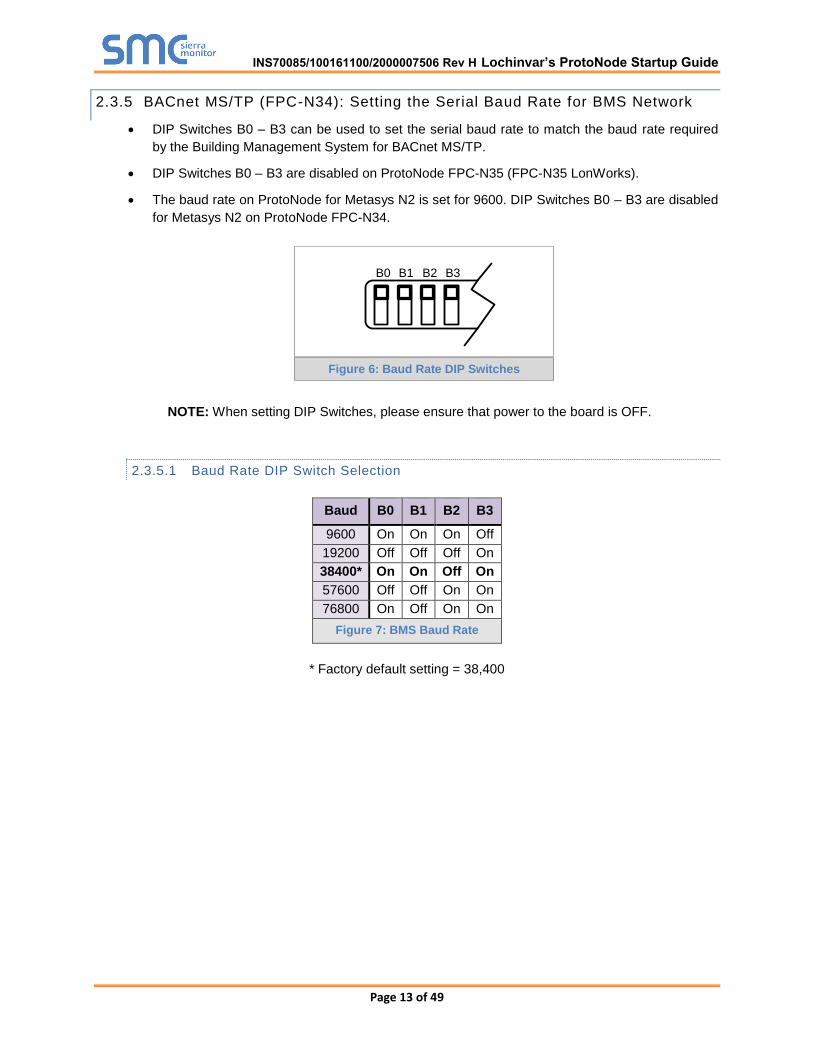
2.3.5 BACnet MS/TP (FPC-N34): Setting the Serial Baud Rate for BMS Network
DIP Switches B0 – B3 can be used to set the serial baud rate to match the baud rate required
by the Building Management System for BACnet MS/TP.
DIP Switches B0 – B3 are disabled on ProtoNode FPC-N35 (FPC-N35 LonWorks).
The baud rate on ProtoNode for Metasys N2 is set for 9600. DIP Switches B0 – B3 are disabled
for Metasys N2 on ProtoNode FPC-N34.
B0 B1 B2 B3
NOTE: When setting DIP Switches, please ensure that power to the board is OFF.
2.3.5.1 Baud Rate DIP Switch Selection
Baud B0 B1 B2 B3
9600 On On On Off
19200 Off Off Off On
38400* On On Off On
57600 Off Off On On
76800 On Off On On
Figure 7: BMS Baud Rate
* Factory default setting = 38,400
Figure 6: Baud Rate DIP Switches
INS70085/100161100/2000007506 Rev H Lochinvar’s ProtoNode Startup Guide
Page 14 of 49
3 INTERFACING PROTONODE TO DEVICES
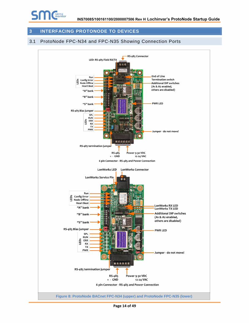
3.1 ProtoNode FPC-N34 and FPC-N35 Showing Connection Ports
Figure 8: ProtoNode BACnet FPC-N34 (upper) and ProtoNode FPC-N35 (lower)
INS70085/100161100/2000007506 Rev H Lochinvar’s ProtoNode Startup Guide
Page 15 of 49
3.2 Device Connections to ProtoNode
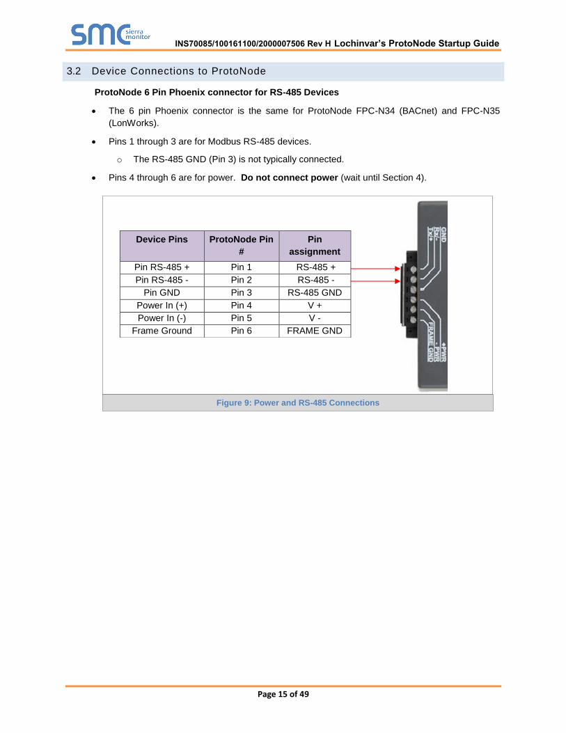
ProtoNode 6 Pin Phoenix connector for RS-485 Devices
The 6 pin Phoenix connector is the same for ProtoNode FPC-N34 (BACnet) and FPC-N35
(LonWorks).
Pins 1 through 3 are for Modbus RS-485 devices.
o The RS-485 GND (Pin 3) is not typically connected.
Pins 4 through 6 are for power. Do not connect power (wait until Section 4).
Device Pins ProtoNode Pin
#
Pin
assignment
Pin RS-485 + Pin 1 RS-485 +
Pin RS-485 - Pin 2 RS-485 -
Pin GND Pin 3 RS-485 GND
Power In (+) Pin 4 V +
Power In (-) Pin 5 V -
Frame Ground Pin 6 FRAME GND
Figure 9: Power and RS-485 Connections
INS70085/100161100/2000007506 Rev H Lochinvar’s ProtoNode Startup Guide

Page 16 of 49
3.2.1 End of Line Termination Switch for the Modbus RS-485 Device Network
On long RS-485 cabling runs, the RS-485 trunk must be properly terminated at each end.
The ProtoNode has an End Of Line (EOL) blue jumper. The default setting for this Blue EOL
switch is OFF with the jumper straddling the pins closest to the inside of the board of the
ProtoNode.
o On short cabling runs the EOL switch does not to need to be turned ON.
If the ProtoNode is placed at one of the ends of the trunk, set the blue EOL jumper to the
ON position straddling the pins closest to the outside of the board of the ProtoNode.
Always leave the single Red Jumper in the A position (default factory setting).
Modbus RS-485
EOL Switch
Leave in A Position
Figure 10: Modbus RS-485 End-Of-Line Termination Switch on the ProtoNode N34 (left) and
ProtoNode N35 (right)
INS70085/100161100/2000007506 Rev H Lochinvar’s ProtoNode Startup Guide
Page 17 of 49
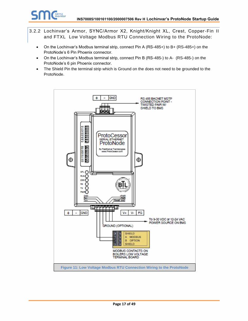
3.2.2 Lochinvar’s Armor, SYNC/Armor X2, Knight/Knight XL, Crest, Copper -Fin II
and FTXL Low Voltage Modbus RTU Connection Wiring to the ProtoNode:
On the Lochinvar’s Modbus terminal strip, connect Pin A (RS-485+) to B+ (RS-485+) on the
ProtoNode’s 6 Pin Phoenix connector.
On the Lochinvar’s Modbus terminal strip, connect Pin B (RS-485-) to A- (RS-485-) on the
ProtoNode’s 6 pin Phoenix connector.
The Shield Pin the terminal strip which is Ground on the does not need to be grounded to the
ProtoNode.
Figure 11: Low Voltage Modbus RTU Connection Wiring to the ProtoNode
INS70085/100161100/2000007506 Rev H Lochinvar’s ProtoNode Startup Guide
Page 18 of 49
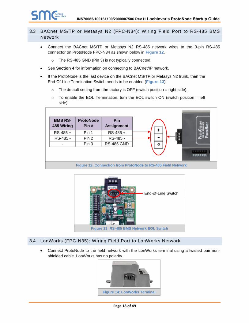
3.3 BACnet MS/TP or Metasys N2 (FPC-N34): Wiring Field Port to RS-485 BMS
Network
Connect the BACnet MS/TP or Metasys N2 RS-485 network wires to the 3-pin RS-485
connector on ProtoNode FPC-N34 as shown below in Figure 12.
o The RS-485 GND (Pin 3) is not typically connected.
See Section 4 for information on connecting to BACnet/IP network.
If the ProtoNode is the last device on the BACnet MS/TP or Metasys N2 trunk, then the
End-Of-Line Termination Switch needs to be enabled (Figure 13).
o The default setting from the factory is OFF (switch position = right side).
o To enable the EOL Termination, turn the EOL switch ON (switch position = left
side).
3.4 LonWorks (FPC-N35): Wiring Field Port to LonWorks Network
Connect ProtoNode to the field network with the LonWorks terminal using a twisted pair non-
shielded cable. LonWorks has no polarity.
BMS RS-
485 Wiring
ProtoNode
Pin #
Pin
Assignment
RS-485 + Pin 1 RS-485 +
RS-485 - Pin 2 RS-485 -
- Pin 3 RS-485 GND
Figure 14: LonWorks Terminal
End-of-Line Switch
Figure 13: RS-485 BMS Network EOL Switch
G
-
+ Figure 12: Connection from ProtoNode to RS-485 Field Network
INS70085/100161100/2000007506 Rev H Lochinvar’s ProtoNode Startup Guide
Page 19 of 49
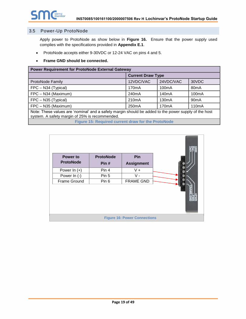
3.5 Power-Up ProtoNode
Apply power to ProtoNode as show below in Figure 16. Ensure that the power supply used
complies with the specifications provided in Appendix E.1.
ProtoNode accepts either 9-30VDC or 12-24 VAC on pins 4 and 5.
Frame GND should be connected.
Power Requirement for ProtoNode External Gateway
Current Draw Type
ProtoNode Family 12VDC/VAC 24VDC/VAC 30VDC
FPC – N34 (Typical) 170mA 100mA 80mA
FPC – N34 (Maximum) 240mA 140mA 100mA
FPC – N35 (Typical) 210mA 130mA 90mA
FPC – N35 (Maximum) 250mA 170mA 110mA
Note: These values are ‘nominal’ and a safety margin should be added to the power supply of the host system. A safety margin of 25% is recommended.
Figure 15: Required current draw for the ProtoNode
Power to
ProtoNode
ProtoNode
Pin #
Pin
Assignment
Power In (+) Pin 4 V +
Power In (-) Pin 5 V -
Frame Ground Pin 6 FRAME GND
Figure 16: Power Connections
INS70085/100161100/2000007506 Rev H Lochinvar’s ProtoNode Startup Guide

Page 20 of 49
4 BACNET/IP AND MODBUS TCP/IP: CHANGE THE PROTONODE IP
ADDRESS
4.1 Connect the PC to ProtoNode via the Ethernet Port
Connect a Cat 5 Ethernet cable (Straight through or Cross-Over) between the PC and
ProtoNode.
The Default IP Address of ProtoNode is 192.168.1.24, Subnet Mask is 255.255.255.0. If the PC
and ProtoNode are on different IP Networks, assign a static IP Address to the PC on the
192.168.1.xxx network.
Go to > >
Right-click on Local Area Connection > Properties
Highlight >
Select: Use the following IP address
Click twice
INS70085/100161100/2000007506 Rev H Lochinvar’s ProtoNode Startup Guide

Page 21 of 49
4.2 BACnet/IP and Modbus TCP/IP: Setting IP Address for Field Network
After setting your PC to be on the same subnet as the ProtoNode (Section 3.5), open a web
browser on your PC and enter the IP address of the ProtoNode; the default address is
192.168.1.24.
The Web Configurator will be displayed as the landing page (Figure 19)
From the Web Configurator landing page, click on the “Diagnostics & Debugging” button in the
bottom right side of the page to access the FST Web GUI.
Figure 17: Web Configuration Screen
INS70085/100161100/2000007506 Rev H Lochinvar’s ProtoNode Startup Guide

Page 22 of 49
From the FST Web GUI’s landing page, click on “Setup” to expand the navigation tree and then
select “Network Settings” to access the IP Settings menu. (Figure 18)
Enter the new IP address for the ProtoNode’s Ethernet port in the “N1 IP address” field.
If necessary, change the Subnet Mask setting in the “N1 Netmask” field.
If necessary, change the IP Gateway setting in the “Default Gateway” field.
Note: If the ProtoNode is connected to a router, the IP Gateway of the ProtoNode should be
set to the IP address of the router that it is connected to.
Click the “System Restart” button at the bottom of the page to apply changes and restart the
ProtoNode.
Unplug Ethernet cable from PC and connect the ProtoNode to the network hub or router.
Record the IP address assigned to the ProtoNode for future reference.
Figure 18: Changing IP Address via FST Web GUI
INS70085/100161100/2000007506 Rev H Lochinvar’s ProtoNode Startup Guide

Page 23 of 49
5 BACNET MS/TP AND BACNET/IP: SETTING NODE_OFFSET TO ASSIGN
SPECIFIC DEVICE INSTANCES
After setting your PC to be on the same subnet as the ProtoNode (Section 4.1), open a web
browser on your PC and enter the IP address of the ProtoNode; the default address is
192.168.1.24.
The Web Configurator will be displayed as your landing page. (Figure 19)
Node_Offset field will be presented displaying the current value (default = 50,000).
Change the value of Node_Offset to establish the desired Device Instance values, and click
SUBMIT.
o Given that: Device Instance = Node_Offset + A Bank Setting
o Then: Node_Offset (required) = Device Instance (desired) – A Bank Setting
For example:
o Device 1 has a Modbus Node-ID of 1
o Device 2 has a Modbus Node-ID of 2
o Device 3 has a Modbus Node-ID of 3
o “A” Bank DIP switches setting = 11
o Desired Device Instance for 1st device = 1,011
o Node_Offset (required) = 1,011 – (A Bank Setting) = 1,011 – 11 = 1,000
o The Node_Offset value will be applied to all devices.
o Device 1 Instance will then be = 1,000 + A Bank Setting = 1,000 + 11 = 1,011
o Device 2 Instance will then be = Previous Value + 1 = 1,011 + 1 = 1,012
o Device 3 Instance will then be = Previous Value + 1 = 1,012 + 1 = 1,013
Figure 19: Web Configurator screen
INS70085/100161100/2000007506 Rev H Lochinvar’s ProtoNode Startup Guide

Page 24 of 49
6 LONWORKS (FPC-N35): COMMISSIONING PROTONODE ON A LONWORKS NETWORK
Commissioning may only be performed by the LonWorks administrator.
6.1 Commissioning ProtoNode FPC-N35 on a LonWorks Network
The User will be prompted by the LonWorks Administrator to hit the Service Pin on the ProtoNode
FPC-N35 at the correct step of the Commissioning process which is different for each LonWorks
Network Management Tool.
If an XIF file is required, see steps in Section 6.1.1 to generate XIF
6.1.1 Instructions to Download XIF File from ProtoNode FPC-N35 Using Browser
Connect a Cat 5 Ethernet cable (Straight through or Cross-Over) between the PC and
ProtoNode.
The Default IP Address of ProtoNode is 192.168.1.24, Subnet Mask is 255.255.255.0. If the
PC and ProtoNode are on different IP Networks, assign a static IP Address to the PC on the
192.168.1.xxx network.
For Windows XP:
Go to > >
Right-click on Local Area Connection > Properties
Highlight >
For Windows 7:
Go to > >
> >
Right-click on Local Area Connection > Properties
Highlight >
Figure 20: LonWorks Service Pin Location
INS70085/100161100/2000007506 Rev H Lochinvar’s ProtoNode Startup Guide
Page 25 of 49
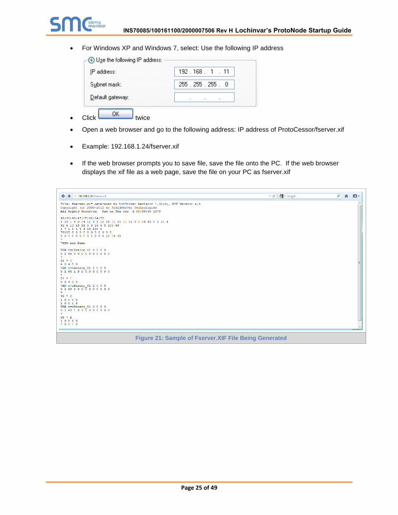
For Windows XP and Windows 7, select: Use the following IP address
Click twice
Open a web browser and go to the following address: IP address of ProtoCessor/fserver.xif
Example: 192.168.1.24/fserver.xif
If the web browser prompts you to save file, save the file onto the PC. If the web browser
displays the xif file as a web page, save the file on your PC as fserver.xif
Figure 21: Sample of Fserver.XIF File Being Generated
INS70085/100161100/2000007506 Rev H Lochinvar’s ProtoNode Startup Guide

Page 26 of 49
7 CAS BACNET EXPLORER FOR VALIDATING PROTONODE IN THE FIELD
ProtoCessor has arranged a complementary 2 week fully functional copy of CAS BACnet Explorer
(through Chipkin Automation) that can be used to validate BACnet MS/TP and/or BACnet/IP
communications of ProtoNode in the field without having to have the BMS Integrator on site. A
Serial or USB to RS-485 converter is needed to test BACnet MS/TP.
7.1 Downloading the CAS Explorer and Requesting an Activation Key
To request the complementary BACnet CAS key, go to
http://app.chipkin.com/activation/twoweek/ and fill in all the information. Enter Vendor Code
“lochinvar12”. Once completed, the email address that was submitted will be registered.
Go to the following web site, download and install the CAS BACnet Explorer to your PC:
http://www.chipkin.com/technical-resources/cas-bacnet-explorer/
Open CAS BACnet Explorer; in the CAS Activation form, enter the email address that was
registered and click on “Request a key”. The CAS key will then be emailed to the registered
address. Cut/paste key from email into the Product key field and click “Activate”.
Figure 22: Downloading the CAS Explorer
Figure 23: Requesting CAS Activation Key
INS70085/100161100/2000007506 Rev H Lochinvar’s ProtoNode Startup Guide

Page 27 of 49
7.2 CAS BACnet Setup
These are the instructions to set CAS Explorer up for the first time on BACnet MS/ST and
BACnet/IP.
7.2.1 CAS BACnet MS/TP Setup
Using the Serial or USB to RS-485 converter, connect it to your PC and the 3 Pin BACnet
MS/TP connector on ProtoNode FPC-N34.
In CAS Explorer, do the following:
o Click on settings
o Check the BACnet MS/TP box and uncheck the BACnet/IP and BACnet Ethernet
boxes
o Set the BACnet MS/TP MAC address to 0
o Set the BACnet MS/TP Baud Rate to 38400
o Click Ok
o On the bottom right-hand corner, make sure that the BACnet MS/TP box is green
o Click on discover
o Check all 4 boxes
o Click Send
7.2.2 CAS BACnet BACnet/IP Setup
See Section 4.1 to set the IP address and subnet of the PC that will be running the CAS
Explorer.
Connect a straight through or cross Ethernet cable from the PC to ProtoNode.
In CAS Explorer, do the following:
o Click on settings
o Check the BACnet/IP box and uncheck the BACnet MS/TP and BACnet Ethernet
boxes
o In the “Select a Network Device” box, select the network card of the PC by clicking on
it
o Click Ok
o On the bottom right-hand corner, make sure that the BACnet/IP box is green
o Click on discover
o Check all 4 boxes
o Click Send
INS70085/100161100/2000007506 Rev H Lochinvar’s ProtoNode Startup Guide
Page 28 of 49
Appendix A. Troubleshooting
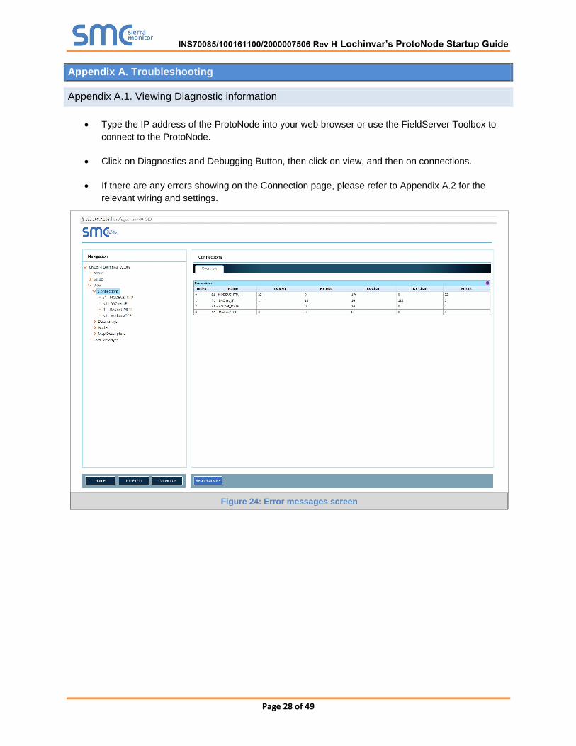
Appendix A.1. Viewing Diagnostic information
Type the IP address of the ProtoNode into your web browser or use the FieldServer Toolbox to
connect to the ProtoNode.
Click on Diagnostics and Debugging Button, then click on view, and then on connections.
If there are any errors showing on the Connection page, please refer to Appendix A.2 for the
relevant wiring and settings.
Figure 24: Error messages screen
INS70085/100161100/2000007506 Rev H Lochinvar’s ProtoNode Startup Guide

Page 29 of 49
Appendix A.2. Check Wiring and Settings
No COMS on Modbus RTU side. If Tx/Rx are not flashing rapidly then there is a COM issue on
the Modbus side and you need to check the following things:
o Visual observations of LEDs on ProtoNode. (Appendix A.5)
o Check baud rate, parity, data bits, stop bits
o Check Modbus device address
o Verify wiring
o Verify all the Modbus RTU devices that were discovered in FST Web Configurator.
(Section 5)
Field COM problems:
o Visual observations of LEDs on ProtoNode. (Appendix A.5)
o Visual dipswitch settings (using correct baud rate and device instance)
o Verify IP address setting
o Verify wiring
If the problem still exists, a Diagnostic Capture needs to be taken and sent to Sierra Monitor
Corporation. (Appendix A.3)
Appendix A.3. Take Diagnostic Capture With the FieldServer Utilities
Once the Diagnostic Capture is complete, email it to [email protected]. The
Diagnostic Capture will allow us to rapidly diagnose the problem.
Ensure that FieldServer Toolbox is Loaded on the PC that is currently being used, or download
FieldServer-Toolbox.zip on the Sierra Monitor Corporation webpage, under Customer Care:
Resource Center, Software Downloads:
http://www.sierramonitor.com/customer-care/resource-center?filters=software-downloads
Extract the executable file and complete the installation.
Disable any wireless Ethernet adapters on the PC/Laptop
Disable firewall and virus protection software if possible
Connect a standard cat5 Ethernet cable between the PC and ProtoNode
Double click on the FS Toolbox Utility
Ethernet Port
Figure 25: Ethernet Port Location
INS70085/100161100/2000007506 Rev H Lochinvar’s ProtoNode Startup Guide
Page 30 of 49
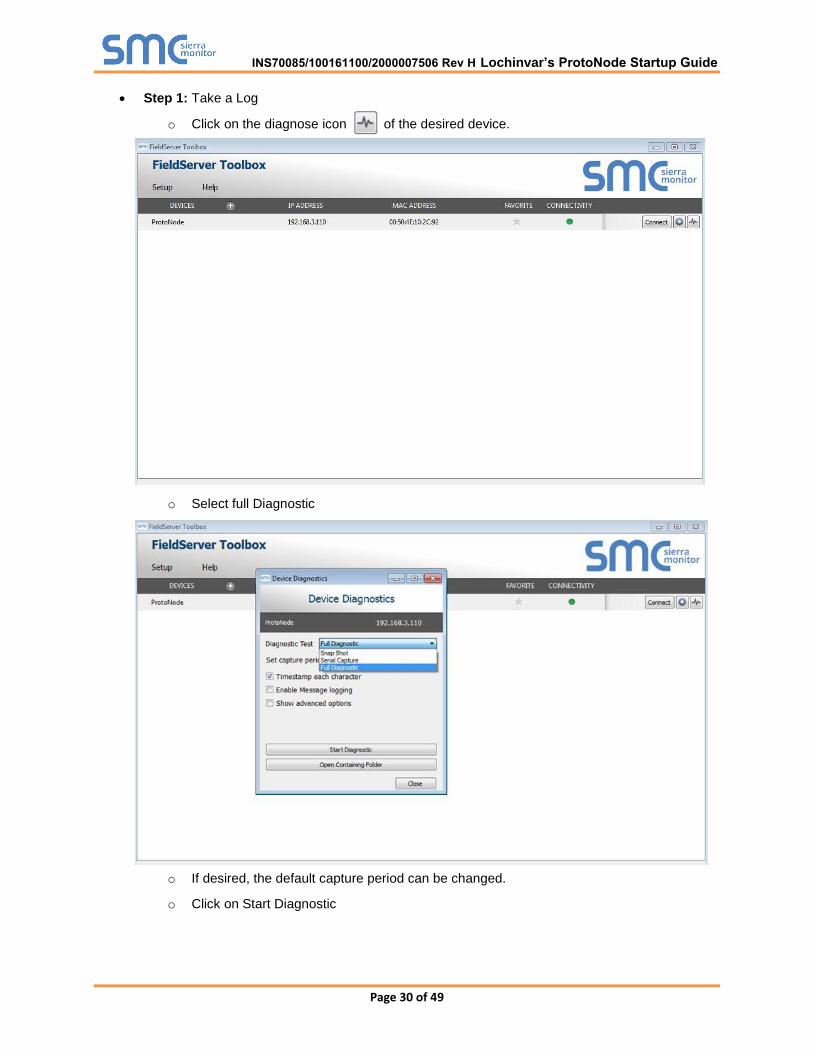
Step 1: Take a Log
o Click on the diagnose icon of the desired device.
o Select full Diagnostic
o If desired, the default capture period can be changed.
o Click on Start Diagnostic
INS70085/100161100/2000007506 Rev H Lochinvar’s ProtoNode Startup Guide
Page 31 of 49
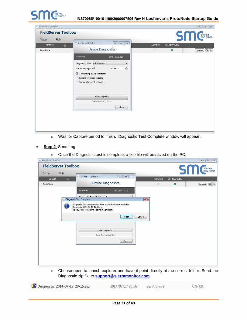
o Wait for Capture period to finish. Diagnostic Test Complete window will appear.
Step 2: Send Log
o Once the Diagnostic test is complete, a .zip file will be saved on the PC.
o Choose open to launch explorer and have it point directly at the correct folder. Send the
Diagnostic zip file to [email protected]
INS70085/100161100/2000007506 Rev H Lochinvar’s ProtoNode Startup Guide
Page 32 of 49
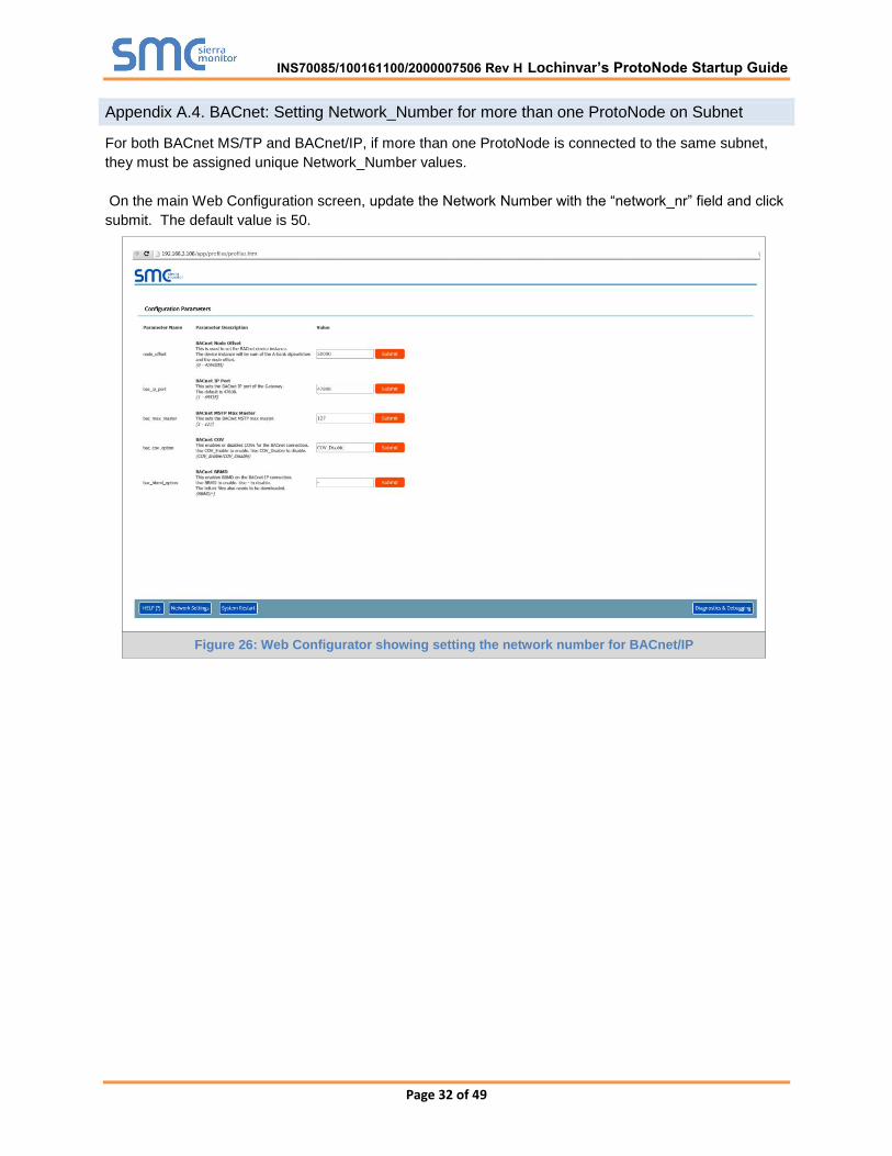
Appendix A.4. BACnet: Setting Network_Number for more than one ProtoNode on Subnet
For both BACnet MS/TP and BACnet/IP, if more than one ProtoNode is connected to the same subnet,
they must be assigned unique Network_Number values.
On the main Web Configuration screen, update the Network Number with the “network_nr” field and click
submit. The default value is 50.
Figure 26: Web Configurator showing setting the network number for BACnet/IP
INS70085/100161100/2000007506 Rev H Lochinvar’s ProtoNode Startup Guide

Page 33 of 49
Appendix A.5. LED Diagnostics for Modbus RTU Communications Between ProtoNode and Devices
Please see the diagram below for ProtoNode FPC-N34 and FPC-N35 LED Locations.
Tag Description
SPL The SPL LED will light if the ProtoNode is off line.
RUN The RUN LED will start flashing 20 seconds after power indicating normal operation.
ERR
The SYS ERR LED will go on solid 15 seconds after power up. It will turn off after 5 seconds. A steady red light will indicate there is a system error on ProtoNode. If this occurs, immediately report the related “system error” shown in the error screen of the GUI interface to FieldServer Technologies for evaluation.
RX The RX LED will flash when a message is received on the host port.
TX The TX LED will flash when a message is sent on the host port.
PWR This is the power light and should show steady green at all times when ProtoNode is powered.
Appendix A.6. Passwords
Access to the ProtoNode can be restricted by enabling a password. There are 2 access levels defined by
2 account names: Admin and User.
The Admin account has unrestricted access to the ProtoNode.
The User account can view any ProtoNode information, but cannot make any changes or
restart the ProtoNode.
The password needs to be a minimum of eight characters and is case sensitive.
If you forgot your password, click cancel on the password authentication popup window, and e-mail the
Password recovery token to [email protected] to receive a temporary password from the Sierra
Monitor support team. You can now access the ProtoNode to set a new password.
Diagnostic LEDs
Figure 27: Diagnostic LEDs
INS70085/100161100/2000007506 Rev H Lochinvar’s ProtoNode Startup Guide
Page 34 of 49
Appendix B. Additional Features
Appendix B.1. DIP switch settings to support Metasys N2
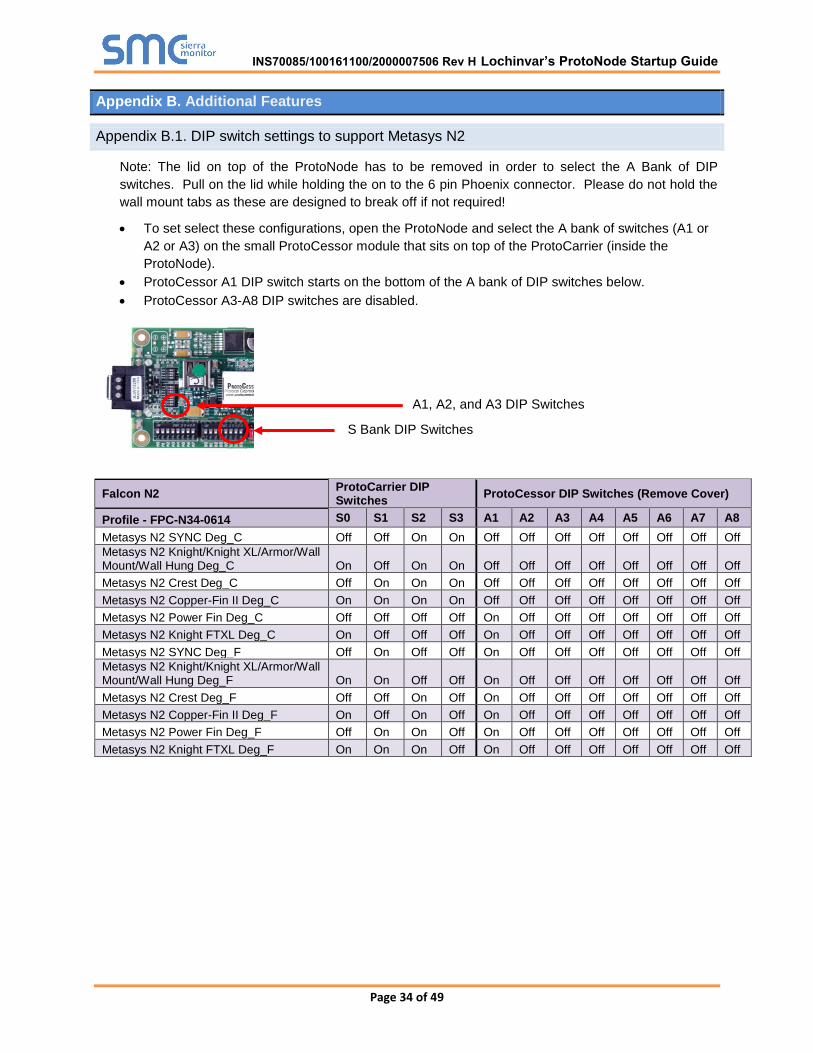
Note: The lid on top of the ProtoNode has to be removed in order to select the A Bank of DIP
switches. Pull on the lid while holding the on to the 6 pin Phoenix connector. Please do not hold the
wall mount tabs as these are designed to break off if not required!
To set select these configurations, open the ProtoNode and select the A bank of switches (A1 or
A2 or A3) on the small ProtoCessor module that sits on top of the ProtoCarrier (inside the
ProtoNode).
ProtoCessor A1 DIP switch starts on the bottom of the A bank of DIP switches below.
ProtoCessor A3-A8 DIP switches are disabled.
Falcon N2 ProtoCarrier DIP Switches
ProtoCessor DIP Switches (Remove Cover)
Profile - FPC-N34-0614 S0 S1 S2 S3 A1 A2 A3 A4 A5 A6 A7 A8
Metasys N2 SYNC Deg_C Off Off On On Off Off Off Off Off Off Off Off
Metasys N2 Knight/Knight XL/Armor/Wall Mount/Wall Hung Deg_C On Off On On Off Off Off Off Off Off Off Off
Metasys N2 Crest Deg_C Off On On On Off Off Off Off Off Off Off Off
Metasys N2 Copper-Fin II Deg_C On On On On Off Off Off Off Off Off Off Off
Metasys N2 Power Fin Deg_C Off Off Off Off On Off Off Off Off Off Off Off
Metasys N2 Knight FTXL Deg_C On Off Off Off On Off Off Off Off Off Off Off
Metasys N2 SYNC Deg_F Off On Off Off On Off Off Off Off Off Off Off
Metasys N2 Knight/Knight XL/Armor/Wall Mount/Wall Hung Deg_F On On Off Off On Off Off Off Off Off Off Off
Metasys N2 Crest Deg_F Off Off On Off On Off Off Off Off Off Off Off
Metasys N2 Copper-Fin II Deg_F On Off On Off On Off Off Off Off Off Off Off
Metasys N2 Power Fin Deg_F Off On On Off On Off Off Off Off Off Off Off
Metasys N2 Knight FTXL Deg_F On On On Off On Off Off Off Off Off Off Off
S Bank DIP Switches
A1, A2, and A3 DIP Switches
INS70085/100161100/2000007506 Rev H Lochinvar’s ProtoNode Startup Guide

Page 35 of 49
Appendix C. Vendor Information - Lochinvar
Appendix C.1. Sync Modbus RTU Mappings to BACnet MS/TP, BACnet/IP, Metasys N2 and LonWorks
Point Name BACnet Object Type
BACnet Object ID
N2 Data Type
N2 Point
Address Lon Name Lon SNVT
Boiler Enable/Room Thermostat 1/Stg 1 BV 1 DO 1 i/oBlrEn_Stg1 SNVT_switch
Tank Thermostat BV 2 DO 2 i/oTankThermostat SNVT_switch
Manual Reset High Limit 1 BI 3 DI 3 oManResHiLim1 SNVT_switch
Flow Switch 1 BI 4 DI 4 oFLoSw1 SNVT_switch
Gas Pressure Switch 1 BI 5 DI 5 oGasPrsSw1 SNVT_switch
Louver Proving Switch 1 BI 6 DI 6 oLouverProvSw1 SNVT_switch
Air Pressure Switch/Flap Vlv 1 BI 7 DI 7 oAirPrsSwFlpVlv1 SNVT_switch
Blocked Drain Switch 1 BI 8 DI 8 oBlockedDrainSw1 SNVT_switch
Auto Reset High Limit 1 BI 9 DI 9 oAutoResHiLim1 SNVT_switch
Flame 1 BI 10 DI 10 oFlame1 SNVT_switch
Enable/Room Thermostat 1/Stg 1 BI 11 DI 11 oEnRmThermStg1 SNVT_switch
Tank Thermostat BI 12 DI 12 oTnkThermostat SNVT_switch
Manual Reset High Limit 2 BI 13 DI 13 oManResHiLim2 SNVT_switch
Flow Switch 2 BI 14 DI 14 oFLoSw2 SNVT_switch
Gas Pressure Switch 2 BI 15 DI 15 oGasPrsSw2 SNVT_switch
Louver Proving Switch 2 BI 16 DI 16 oLouverProvSw2 SNVT_switch
Air Pressure Switch/Flap Vlv 2 BI 17 DI 17 oAirPrsSwFlpVlv2 SNVT_switch
Blocked Drain Switch 2 BI 18 DI 18 oBlockedDrainSw2 SNVT_switch
Flame 2 BI 19 DI 19 oFlame2 SNVT_switch
Run-time Contacts BI 20 DI 20 oRunTimeContcts SNVT_switch
Alarm Contacts 1 BI 21 DI 21 oAlarmContacts1 SNVT_switch
CH Pump 1 BI 22 DI 22 oCHPump1 SNVT_switch
DHW Pump 1 BI 23 DI 23 oDHWPump1 SNVT_switch
Gas Vlv 1 BI 24 DI 24 oGasVlv1 SNVT_switch
System Pump BI 25 DI 25 oSystemPump SNVT_switch
Run-time Contacts 2 BI 26 DI 26 oRunTimeContcts2 SNVT_switch
Alarm Contacts 2 BI 27 DI 27 oAlarmContacts2 SNVT_switch
CH Pump 2 BI 28 DI 28 oCHPump2 SNVT_switch
Gas Vlv 2 BI 29 DI 29 oGasVlv2 SNVT_switch
INS70085/100161100/2000007506 Rev H Lochinvar’s ProtoNode Startup Guide

Page 36 of 49
Discrete Inputs 1 - 16 AI 30 AI 30 oDiscInputs1_16 SNVT_count_f
Discrete Inputs 17 - 32 AI 31 AI 31 oDiscInputs17_32 SNVT_count_f
Discrete Inputs 33 - 48 AI 32 AI 32 oDiscInputs33_48 SNVT_count_f
System/Cascade Setpoint AI 33 AI 33 oSysCascadeSP SNVT_temp_p
Cascade Total Power AI 34 AI 34 oCascadeTotalPwr SNVT_lev_percent
Cascade Current Power AI 35 AI 35 oCascadeCrrntPwr SNVT_lev_percent
Outlet Setpoint 1 AI 36 AI 36 oOutletSP1 SNVT_temp_p
Outlet Temperature 1 AI 37 AI 37 oOutletTmp1 SNVT_temp_p
Inlet Temperature 1 AI 38 AI 38 oInletTmp1 SNVT_temp_p
Flue Temperature 1 AI 39 AI 39 oFlueTmp1 SNVT_temp_p
Firing Rate 1 AI 40 AI 40 oFiringRate1 SNVT_lev_percent
Boiler 1 Status Code AI 41 AI 41 oBlr1StatusCode SNVT_count_f
Boiler 1 Blocking Code AI 42 AI 42 oBlr1BlckngCode SNVT_count_f
Boiler 1 Lockout Code AI 43 AI 43 oBlr1LockoutCode SNVT_count_f
Outlet Setpoint 2 AI 44 AI 44 oOutletSP2 SNVT_temp_p
Outlet Temperature 2 AI 45 AI 45 oOutletTmp2 SNVT_temp_p
Inlet Temperature 2 AI 46 AI 46 oInletTmp2 SNVT_temp_p
Flue Temperature 2 AI 47 AI 47 oFlueTmp2 SNVT_temp_p
Firing Rate 2 AI 48 AI 48 oFiringRate2 SNVT_lev_percent
Boiler 2 Status Code AI 49 AI 49 oBlr2StatusCode SNVT_count_f
Boiler 2 Blocking Code AI 50 AI 50 oBlr2BlckngCode SNVT_count_f
Boiler 2 Lockout Code AI 51 AI 51 oBlr2LockoutCode SNVT_count_f
Configuration AV 52 AO 52 i/oConfiguration SNVT_count_f
Coils AV 53 AO 53 i/oCoils SNVT_count_f
0-10 Volt Input/Rate Cmd/SP Cmd AV 54 AO 54 i/o0_10VltInRtCmd SNVT_lev_percent
Tank Setpoint AV 55 AO 55 i/oTankSP SNVT_temp_p
Tank Temperature AV 56 AO 56 i/oTankTmp SNVT_temp_p
Outdoor Temperature AV 57 AO 57 i/oOutdoorTmp SNVT_temp_p
System Supply Temperature AV 58 AO 58 i/oSysSupplyTmp SNVT_temp_p
Appendix C.2. Knight Modbus RTU Mappings to BACnet MS/TP, BACnet/IP, Metasys N2 and LonWorks
Point Name BACnet Object Type
BACnet Object ID
N2 Data Type
N2 Point
Address Lon Name Lon SNVT
INS70085/100161100/2000007506 Rev H Lochinvar’s ProtoNode Startup Guide

Page 37 of 49
Room Thermostat 1 BV 1 DO 1 i/oRmThermostat1 SNVT_switch
Room Thermostat 2 BV 2 DO 2 i/oRmThermostat2 SNVT_switch
Room Thermostat 3 BV 3 DO 3 i/oRmThermostat3 SNVT_switch
Tank Thermostat BV 4 DO 4 i/oTankThermostat SNVT_switch
Flow Switch BI 5 DI 5 oFlowSw SNVT_switch
Gas Pressure Switch BI 6 DI 6 oGasPressureSw SNVT_switch
Louver Proving Switch BI 7 DI 7 oLouverPrvingSw SNVT_switch
Air Pressure Switch BI 8 DI 8 oAirPressureSw SNVT_switch
Blocked Drain Switch BI 9 DI 9 oBlockedDrainSw SNVT_switch
Auto Reset High Limit BI 10 DI 10 oAutoResetHiLim SNVT_switch
Flame BI 11 DI 11 oFlame SNVT_switch
Room Thermostat 1 BI 12 DI 12 oRmThrmostat1 SNVT_switch
Tank Thermostat BI 13 DI 13 oTnkThrmostat SNVT_switch
Room Thermostat 2 BI 14 DI 14 oRmThrmostat2 SNVT_switch
Run-time Contacts BI 15 DI 15 oRunTimeContacts SNVT_switch
Alarm Contacts BI 16 DI 16 oAlarmContacts SNVT_switch
CH Pump BI 17 DI 17 oCHPump SNVT_switch
DHW Pump BI 18 DI 18 oDHWPump SNVT_switch
Gas Valve BI 19 DI 19 oGasValve SNVT_switch
System Pump BI 20 DI 20 oSystemPump SNVT_switch
Discrete Inputs 1 - 16 AI 21 AI 21 oDiscInputs1-16 SNVT_count_f
Discrete Inputs 17 - 32 AI 22 AI 22 oDiscInputs17-32 SNVT_count_f
Discrete Inputs 33 - 48 AI 23 AI 23 oDiscInputs33-48 SNVT_count_f
System Cascade Setpoint AI 24 AI 24 oSystemCascadeSP SNVT_temp_p
System Pump Speed AI 25 AI 25 oSystemPumpSpeed SNVT_lev_percent
Cascade Total Power AI 26 AI 26 oCascadeTotalPwr SNVT_lev_percent
Cascade Current Power AI 27 AI 27 oCascadeCrrntPwr SNVT_lev_percent
Outlet Setpoint AI 28 AI 28 oOutletSP SNVT_temp_p
Outlet Temperature AI 29 AI 29 oOutletTmp SNVT_temp_p
Inlet Temperature AI 30 AI 30 oInletTmp SNVT_temp_p
Flue Temperature AI 31 AI 31 oFlueTmp SNVT_temp_p
Firing Rate AI 32 AI 32 oFiringRate SNVT_lev_percent
Boiler Pump Speed AI 33 AI 33 oBlrPumpSpeed SNVT_lev_percent
Boiler Status Code AI 34 AI 34 oBlrStatusCode SNVT_count_f
Boiler Blocking Code AI 35 AI 35 oBlrBlockingCode SNVT_count_f
INS70085/100161100/2000007506 Rev H Lochinvar’s ProtoNode Startup Guide

Page 38 of 49
Boiler Lockout Code AI 36 AI 36 oBlrLockoutCode SNVT_count_f
Configuration AV 37 AO 37 i/oConfiguration SNVT_count_f
Coils AV 38 AO 38 i/oCoils SNVT_count_f
0-10 Volt Input/Rate Cmd/SP Cmd AV 39 AO 39 i/o0_10VltInRtCmd SNVT_lev_percent
Tank Setpoint AV 40 AO 40 i/oTankSP SNVT_temp_p
Tank Temperature AV 41 AO 41 i/oTankTmp SNVT_temp_p
Outdoor Temperature AV 42 AO 42 i/oOutdoorTmp SNVT_temp_p
System Supply Temperature AV 43 AO 43 i/oSystemSupplyTmp SNVT_temp_p
System Return Temperature AV 44 AO 44 i/oSystemReturnTmp SNVT_temp_p
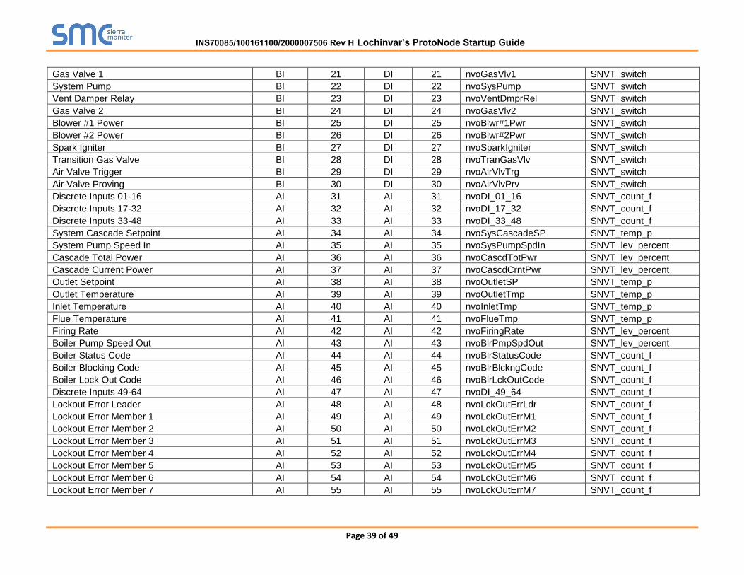
Appendix C.3. Crest Modbus RTU Mappings to BACnet MS/TP, BACnet/IP, Metasys N2 and LonWorks
Point Name BACnet Object Type
BACnet Object ID
N2 Data Type
N2 Point
Address Lon Name Lon SNVT
Boiler Enable BV 1 DO 1 nvi/nvoBoilerEnable SNVT_switch
Tank Thermostat BV 2 DO 2 nvi/nvoTnkThermostat SNVT_switch
Manual Reset High Limit BI 3 DI 3 nvoManResetHiLim SNVT_switch
Flow Switch BI 4 DI 4 nvoFlowSw SNVT_switch
Gas Pressure Switch BI 5 DI 5 nvoGasPrsSw SNVT_switch
Louvers Proving Switch BI 6 DI 6 nvoLouversPrvSw SNVT_switch
Blower Proving Switch 1 BI 7 DI 7 nvoBlwrPrvSw1 SNVT_switch
Blocked Drain Switch BI 8 DI 8 nvoBlkDrainSw SNVT_switch
Flame 1 BI 9 DI 9 nvoFlame1 SNVT_switch
Enable BI 10 DI 10 nvoEnable SNVT_switch
Tank Thermostat BI 11 DI 11 nvoTnkThrmostat SNVT_switch
Blocked Flue BI 12 DI 12 nvoBlockedFlue SNVT_switch
Blower Proving Switch 2 BI 13 DI 13 nvoBlwrPrvSw2 SNVT_switch
Flue Damper Proving Switch BI 14 DI 14 nvoFlueDmprPrvSw SNVT_switch
Flame 2 BI 15 DI 15 nvoFlame2 SNVT_switch
Run Time Contacts BI 16 DI 16 nvoRunTimContcts SNVT_switch
Alarm Contacts BI 17 DI 17 nvoAlarmContacts SNVT_switch
SH Pump BI 18 DI 18 nvoSHPump SNVT_switch
HWG Pump BI 19 DI 19 nvoHWGPump SNVT_switch
Louver Relay BI 20 DI 20 nvoLouverRel SNVT_switch
INS70085/100161100/2000007506 Rev H Lochinvar’s ProtoNode Startup Guide
Page 39 of 49
Gas Valve 1 BI 21 DI 21 nvoGasVlv1 SNVT_switch
System Pump BI 22 DI 22 nvoSysPump SNVT_switch
Vent Damper Relay BI 23 DI 23 nvoVentDmprRel SNVT_switch
Gas Valve 2 BI 24 DI 24 nvoGasVlv2 SNVT_switch
Blower #1 Power BI 25 DI 25 nvoBlwr#1Pwr SNVT_switch
Blower #2 Power BI 26 DI 26 nvoBlwr#2Pwr SNVT_switch
Spark Igniter BI 27 DI 27 nvoSparkIgniter SNVT_switch
Transition Gas Valve BI 28 DI 28 nvoTranGasVlv SNVT_switch
Air Valve Trigger BI 29 DI 29 nvoAirVlvTrg SNVT_switch
Air Valve Proving BI 30 DI 30 nvoAirVlvPrv SNVT_switch
Discrete Inputs 01-16 AI 31 AI 31 nvoDI_01_16 SNVT_count_f
Discrete Inputs 17-32 AI 32 AI 32 nvoDI_17_32 SNVT_count_f
Discrete Inputs 33-48 AI 33 AI 33 nvoDI_33_48 SNVT_count_f
System Cascade Setpoint AI 34 AI 34 nvoSysCascadeSP SNVT_temp_p
System Pump Speed In AI 35 AI 35 nvoSysPumpSpdIn SNVT_lev_percent
Cascade Total Power AI 36 AI 36 nvoCascdTotPwr SNVT_lev_percent
Cascade Current Power AI 37 AI 37 nvoCascdCrntPwr SNVT_lev_percent
Outlet Setpoint AI 38 AI 38 nvoOutletSP SNVT_temp_p
Outlet Temperature AI 39 AI 39 nvoOutletTmp SNVT_temp_p
Inlet Temperature AI 40 AI 40 nvoInletTmp SNVT_temp_p
Flue Temperature AI 41 AI 41 nvoFlueTmp SNVT_temp_p
Firing Rate AI 42 AI 42 nvoFiringRate SNVT_lev_percent
Boiler Pump Speed Out AI 43 AI 43 nvoBlrPmpSpdOut SNVT_lev_percent
Boiler Status Code AI 44 AI 44 nvoBlrStatusCode SNVT_count_f
Boiler Blocking Code AI 45 AI 45 nvoBlrBlckngCode SNVT_count_f
Boiler Lock Out Code AI 46 AI 46 nvoBlrLckOutCode SNVT_count_f
Discrete Inputs 49-64 AI 47 AI 47 nvoDI_49_64 SNVT_count_f
Lockout Error Leader AI 48 AI 48 nvoLckOutErrLdr SNVT_count_f
Lockout Error Member 1 AI 49 AI 49 nvoLckOutErrM1 SNVT_count_f
Lockout Error Member 2 AI 50 AI 50 nvoLckOutErrM2 SNVT_count_f
Lockout Error Member 3 AI 51 AI 51 nvoLckOutErrM3 SNVT_count_f
Lockout Error Member 4 AI 52 AI 52 nvoLckOutErrM4 SNVT_count_f
Lockout Error Member 5 AI 53 AI 53 nvoLckOutErrM5 SNVT_count_f
Lockout Error Member 6 AI 54 AI 54 nvoLckOutErrM6 SNVT_count_f
Lockout Error Member 7 AI 55 AI 55 nvoLckOutErrM7 SNVT_count_f
INS70085/100161100/2000007506 Rev H Lochinvar’s ProtoNode Startup Guide
Page 40 of 49
Configuration AV 56 AO 56 nvi/nvoConfiguration SNVT_count_f
Coils AV 57 AO 57 nvi/nvoCoils SNVT_count_f
0-10 Volt Input AV 58 AO 58 nvi/nvo0_10VoltInput SNVT_lev_percent
Tank Setpoint AV 59 AO 59 nvi/nvoTnkSP SNVT_temp_p
Tank Temperature AV 60 AO 60 nvi/nvoTnkTmp SNVT_temp_p
Outdoor Temperature AV 61 AO 61 nvi/nvoOutdoorTmp SNVT_temp_p
System Supply Temperature AV 62 AO 62 nvi/nvoSysSupplyTmp SNVT_temp_p
System Return Temperature AV 63 AO 63 nvi/nvoSysReturnTmp SNVT_temp_p
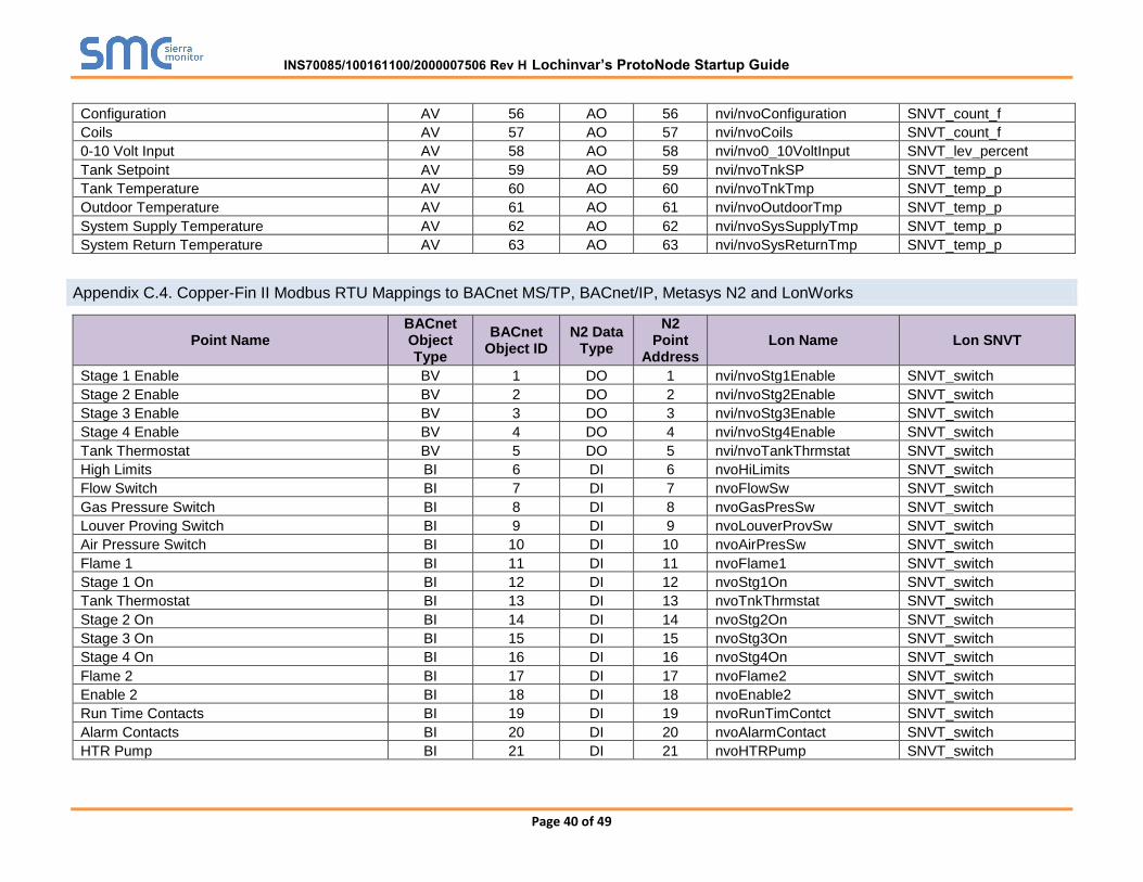
Appendix C.4. Copper-Fin II Modbus RTU Mappings to BACnet MS/TP, BACnet/IP, Metasys N2 and LonWorks
Point Name BACnet Object Type
BACnet Object ID
N2 Data Type
N2 Point
Address Lon Name Lon SNVT
Stage 1 Enable BV 1 DO 1 nvi/nvoStg1Enable SNVT_switch
Stage 2 Enable BV 2 DO 2 nvi/nvoStg2Enable SNVT_switch
Stage 3 Enable BV 3 DO 3 nvi/nvoStg3Enable SNVT_switch
Stage 4 Enable BV 4 DO 4 nvi/nvoStg4Enable SNVT_switch
Tank Thermostat BV 5 DO 5 nvi/nvoTankThrmstat SNVT_switch
High Limits BI 6 DI 6 nvoHiLimits SNVT_switch
Flow Switch BI 7 DI 7 nvoFlowSw SNVT_switch
Gas Pressure Switch BI 8 DI 8 nvoGasPresSw SNVT_switch
Louver Proving Switch BI 9 DI 9 nvoLouverProvSw SNVT_switch
Air Pressure Switch BI 10 DI 10 nvoAirPresSw SNVT_switch
Flame 1 BI 11 DI 11 nvoFlame1 SNVT_switch
Stage 1 On BI 12 DI 12 nvoStg1On SNVT_switch
Tank Thermostat BI 13 DI 13 nvoTnkThrmstat SNVT_switch
Stage 2 On BI 14 DI 14 nvoStg2On SNVT_switch
Stage 3 On BI 15 DI 15 nvoStg3On SNVT_switch
Stage 4 On BI 16 DI 16 nvoStg4On SNVT_switch
Flame 2 BI 17 DI 17 nvoFlame2 SNVT_switch
Enable 2 BI 18 DI 18 nvoEnable2 SNVT_switch
Run Time Contacts BI 19 DI 19 nvoRunTimContct SNVT_switch
Alarm Contacts BI 20 DI 20 nvoAlarmContact SNVT_switch
HTR Pump BI 21 DI 21 nvoHTRPump SNVT_switch
INS70085/100161100/2000007506 Rev H Lochinvar’s ProtoNode Startup Guide

Page 41 of 49
DHW Pump BI 22 DI 22 nvoDHWPump SNVT_switch
Louver Relay BI 23 DI 23 nvoLouverRelay SNVT_switch
Gas Valve 1 BI 24 DI 24 nvoGasValve1 SNVT_switch
System Pump BI 25 DI 25 nvoSysPump SNVT_switch
Gas Valve 2 BI 26 DI 26 nvoGasValve2 SNVT_switch
Gas Valve 3 BI 27 DI 27 nvoGasValve3 SNVT_switch
Gas Valve 4 BI 28 DI 28 nvoGasValve4 SNVT_switch
Discrete Inputs 01-16 AI 29 AI 29 nvoDI_01_16 SNVT_count_f
Discrete Inputs 17-32 AI 30 AI 30 nvoDI_17_32 SNVT_count_f
Discrete Inputs 33-48 AI 31 AI 31 nvoDI_33_48 SNVT_count_f
System Cascade Setpoint AI 32 AI 32 nvoSysCascadeSP SNVT_temp_p
System Pump Speed AI 33 AI 33 nvoSysPumpSpeed SNVT_lev_percent
Cascade Total Power AI 34 AI 34 nvoCascdTotPwr SNVT_lev_percent
Cascade Current Power AI 35 AI 35 nvoCascdCrntPwr SNVT_lev_percent
Outlet Setpoint AI 36 AI 36 nvoOutletSP SNVT_temp_p
Outlet Temperature AI 37 AI 37 nvoOutletTmp SNVT_temp_p
Inlet Temperature AI 38 AI 38 nvoInletTmp SNVT_temp_p
Pool Temperature AI 39 AI 39 nvoPoolTmp SNVT_temp_p
Firing Rate AI 40 AI 40 nvoFiringRate SNVT_lev_percent
Boiler Status Code AI 41 AI 41 nvoBlrStatusCode SNVT_count_f
Boiler Blocking Code AI 42 AI 42 nvoBlrBlckngCode SNVT_count_f
Boiler Lockout Code AI 43 AI 43 nvoBlrLckOutCode SNVT_count_f
Configuration AV 45 AO 45 nvi/nvoConfiguration SNVT_count_f
Coils AV 46 AO 46 nvi/nvoCoils SNVT_count_f
0-10 Volt Input AV 47 AO 47 nvi/nvo0_10VoltInput SNVT_lev_percent
Pool Setpoint AV 48 AO 48 nvi/nvoPoolSetpoint SNVT_temp_p
Tank Temperature AV 49 AO 49 nvi/nvoTankTmp SNVT_temp_p
Outdoor Temperature AV 50 AO 50 nvi/nvoOutdoorTmp SNVT_temp_p
System Supply Temperature AV 51 AO 51 nvi/nvoSysSupplyTmp SNVT_temp_p
System Return Temperature AV 52 AO 52 nvi/nvoSysReturnTmp SNVT_temp_p
Appendix C.5. Power Fin Modbus RTU Mappings to BACnet MS/TP, BACnet/IP, Metasys N2 and LonWorks
Point Name BACnet BACnet N2 Data N2 Lon Name Lon SNVT
INS70085/100161100/2000007506 Rev H Lochinvar’s ProtoNode Startup Guide

Page 42 of 49
Object Type
Object ID Type Point Address
Boiler Enable/Room Thermostat 1/Stg 1 BV 1 DO 1 i/oBlrEn_Stg1 SNVT_switch
Tank Thermostat BV 2 DO 2 i/oTankThermostat SNVT_switch
Manual Reset High Limit 1 BI 3 DI 3 oManResHiLim1 SNVT_switch
Flow Switch 1 BI 4 DI 4 oFLoSw1 SNVT_switch
Gas Pressure Switch 1 BI 5 DI 5 oGasPrsSw1 SNVT_switch
Louver Proving Switch 1 BI 6 DI 6 oLouverProvSw1 SNVT_switch
Air Pressure Switch/Flap Vlv 1 BI 7 DI 7 oAirPrsSwFlpVlv1 SNVT_switch
Blocked Drain Switch 1 BI 8 DI 8 oBlockedDrainSw1 SNVT_switch
Auto Reset High Limit 1 BI 9 DI 9 oAutoResHiLim1 SNVT_switch
Flame 1 BI 10 DI 10 oFlame1 SNVT_switch
Enable/Room Thermostat 1/Stg 1 BI 11 DI 11 oEnRmThermStg1 SNVT_switch
Tank Thermostat BI 12 DI 12 oTnkThermostat SNVT_switch
Run-time Contacts BI 13 DI 13 oRunTimeContcts SNVT_switch
Alarm Contacts 1 BI 14 DI 14 oAlarmContacts1 SNVT_switch
CH Pump 1 BI 15 DI 15 oCHPump1 SNVT_switch
DHW Pump 1 BI 16 DI 16 oDHWPump1 SNVT_switch
Gas Vlv 1 BI 17 DI 17 oGasVlv1 SNVT_switch
System Pump BI 18 DI 18 oSystemPump SNVT_switch
Mains Fan 1 BI 19 DI 19 oMainsFan1 SNVT_switch
External Spark BI 20 DI 20 oExtSpark SNVT_switch
Discrete Inputs 1 - 16 AI 21 AI 21 oDiscInputs1_16 SNVT_count_f
Discrete Inputs 17 - 32 AI 22 AI 22 oDiscInputs17_32 SNVT_count_f
Discrete Inputs 33 - 48 AI 23 AI 23 oDiscInputs33_48 SNVT_count_f
System/Cascade Setpoint AI 24 AI 24 oSysCascadeSP SNVT_temp_p
Cascade Total Power AI 25 AI 25 oCascadeTotalPwr SNVT_lev_percent
Cascade Current Power AI 26 AI 26 oCascadeCrrntPwr SNVT_lev_percent
Outlet Setpoint 1 AI 27 AI 27 oOutletSP1 SNVT_temp_p
Outlet Temperature 1 AI 28 AI 28 oOutletTmp1 SNVT_temp_p
Inlet Temperature 1 AI 29 AI 29 oInletTmp1 SNVT_temp_p
Flue Temperature 1 AI 30 AI 30 oFlueTmp1 SNVT_temp_p
Firing Rate 1 AI 31 AI 31 oFiringRate1 SNVT_lev_percent
Boiler 1 Status Code AI 32 AI 32 oBlr1StatusCode SNVT_count_f
Boiler 1 Blocking Code AI 33 AI 33 oBlr1BlckngCode SNVT_count_f
Boiler 1 Lockout Code AI 34 AI 34 oBlr1LockoutCode SNVT_count_f
INS70085/100161100/2000007506 Rev H Lochinvar’s ProtoNode Startup Guide

Page 43 of 49
Discrete Inputs 49-64 AI 35 AI 35 oDiscInputs49_64 SNVT_count_f
Configuration AV 36 AO 36 i/oConfiguration SNVT_count_f
Coils AV 37 AO 37 i/oCoils SNVT_count_f
0-10 Volt Input/Rate Cmd/SP Cmd AV 38 AO 38 i/o0_10VltInRtCmd SNVT_lev_percent
Tank Setpoint AV 39 AO 39 i/oTankSP SNVT_temp_p
Tank Temperature AV 40 AO 40 i/oTankTmp SNVT_temp_p
Outdoor Temperature AV 41 AO 41 i/oOutdoorTmp SNVT_temp_p
System Supply Temperature AV 42 AO 42 i/oSysSupplyTmp SNVT_temp_p
System Return Temperature AV 43 AO 43 i/oSysReturnTmp SNVT_temp_p
Appendix C.6. Knight FTXL Modbus RTU Mappings to BACnet MS/TP, BACnet/IP, Metasys N2 and LonWorks
Point Name BACnet Object Type
BACnet Object ID
N2 Data Type
N2 Point
Address Lon Name Lon SNVT
Room Thermostat 1 BV 1 DO 1 i/oRmThermostat1 SNVT_switch
Room Thermostat 2 BV 2 DO 2 i/oRmThermostat2 SNVT_switch
Room Thermostat 3 BV 3 DO 3 i/oRmThermostat3 SNVT_switch
Tank Thermostat BV 4 DO 4 i/oTankThermostat SNVT_switch
Flow Switch BI 5 DI 5 oFlowSw SNVT_switch
Gas Pressure Switch BI 6 DI 6 oGasPressureSw SNVT_switch
Louver Proving Switch BI 7 DI 7 oLouverPrvingSw SNVT_switch
Air Pressure Switch BI 8 DI 8 oAirPressureSw SNVT_switch
Blocked Drain Switch BI 9 DI 9 oBlockedDrainSw SNVT_switch
Auto Reset High Limit BI 10 DI 10 oAutoResetHiLim SNVT_switch
Flame BI 11 DI 11 oFlame SNVT_switch
Room Thermostat 1 BI 12 DI 12 oRmThrmostat1 SNVT_switch
Tank Thermostat BI 13 DI 13 oTnkThrmostat SNVT_switch
Room Thermostat 2 BI 14 DI 14 oRmThrmostat2 SNVT_switch
Run-time Contacts BI 15 DI 15 oRunTimeContacts SNVT_switch
Alarm Contacts BI 16 DI 16 oAlarmContacts SNVT_switch
CH Pump BI 17 DI 17 oCHPump SNVT_switch
DHW Pump 1 BI 18 DI 18 oDHWPump1 SNVT_switch
Louver Relay BI 19 DI 19 oLouverRelay SNVT_switch
Gas Valve BI 20 DI 20 oGasValve SNVT_switch
INS70085/100161100/2000007506 Rev H Lochinvar’s ProtoNode Startup Guide

Page 44 of 49
System Pump BI 21 DI 21 oSystemPump SNVT_switch
DHW Pump 2 BI 22 DI 22 oDHWPump2 SNVT_switch
Discrete Inputs 1 - 16 AI 23 AI 23 oDiscInputs1-16 SNVT_count_f
Discrete Inputs 17 - 32 AI 24 AI 24 oDiscInputs17-32 SNVT_count_f
Discrete Inputs 33 - 48 AI 25 AI 25 oDiscInputs33-48 SNVT_count_f
System Cascade Setpoint AI 26 AI 26 oSystemCascadeSP SNVT_temp_p
System Pump Speed AI 27 AI 27 oSystemPumpSpeed SNVT_lev_percent
Cascade Total Power AI 28 AI 28 oCascadeTotalPwr SNVT_lev_percent
Cascade Current Power AI 29 AI 29 oCascadeCrrntPwr SNVT_lev_percent
Outlet Setpoint AI 30 AI 30 oOutletSP SNVT_temp_p
Outlet Temperature AI 31 AI 31 oOutletTmp SNVT_temp_p
Inlet Temperature AI 32 AI 32 oInletTmp SNVT_temp_p
Flue Temperature AI 33 AI 33 oFlueTmp SNVT_temp_p
Firing Rate AI 34 AI 34 oFiringRate SNVT_lev_percent
Boiler Pump Speed AI 35 AI 35 oBlrPumpSpeed SNVT_lev_percent
Boiler Status Code AI 36 AI 36 oBlrStatusCode SNVT_count_f
Boiler Blocking Code AI 37 AI 37 oBlrBlockingCode SNVT_count_f
Boiler Lockout Code AI 38 AI 38 oBlrLockoutCode SNVT_count_f
Configuration AV 39 AO 39 i/oConfiguration SNVT_count_f
Coils AV 40 AO 40 i/oCoils SNVT_count_f
0-10 Volt Input/Rate Cmd/SP Cmd AV 41 AO 41 i/o0_10VltInRtCmd SNVT_lev_percent
Tank Setpoint AV 42 AO 42 i/oTankSP SNVT_temp_p
Tank Temperature AV 43 AO 43 i/oTankTmp SNVT_temp_p
Outdoor Temperature AV 44 AO 44 i/oOutdoorTmp SNVT_temp_p
System Supply Temperature AV 45 AO 45 i/oSystemSupplyTmp SNVT_temp_p
System Return Temperature AV 46 AO 46 i/oSystemReturnTmp SNVT_temp_p
INS70085/100161100/2000007506 Rev H Lochinvar’s ProtoNode Startup Guide

Page 45 of 49
Appendix D. “A” Bank DIP Switch Settings
Appendix D.1. “A” Bank DIP Switch Settings
Address A0 A1 A2 A3 A4 A5 A6 A7
1 On Off Off Off Off Off Off Off
2 Off On Off Off Off Off Off Off
3 On On Off Off Off Off Off Off
4 Off Off On Off Off Off Off Off
5 On Off On Off Off Off Off Off
6 Off On On Off Off Off Off Off
7 On On On Off Off Off Off Off
8 Off Off Off On Off Off Off Off
9 On Off Off On Off Off Off Off
10 Off On Off On Off Off Off Off
11 On On Off On Off Off Off Off
12 Off Off On On Off Off Off Off
13 On Off On On Off Off Off Off
14 Off On On On Off Off Off Off
15 On On On On Off Off Off Off
16 Off Off Off Off On Off Off Off
17 On Off Off Off On Off Off Off
18 Off On Off Off On Off Off Off
19 On On Off Off On Off Off Off
20 Off Off On Off On Off Off Off
21 On Off On Off On Off Off Off
22 Off On On Off On Off Off Off
23 On On On Off On Off Off Off
24 Off Off Off On On Off Off Off
25 On Off Off On On Off Off Off
26 Off On Off On On Off Off Off
27 On On Off On On Off Off Off
28 Off Off On On On Off Off Off
29 On Off On On On Off Off Off
30 Off On On On On Off Off Off
31 On On On On On Off Off Off
32 Off Off Off Off Off On Off Off
33 On Off Off Off Off On Off Off
34 Off On Off Off Off On Off Off
35 On On Off Off Off On Off Off
36 Off Off On Off Off On Off Off
37 On Off On Off Off On Off Off
38 Off On On Off Off On Off Off
39 On On On Off Off On Off Off
40 Off Off Off On Off On Off Off
41 On Off Off On Off On Off Off
42 Off On Off On Off On Off Off
43 On On Off On Off On Off Off
44 Off Off On On Off On Off Off
45 On Off On On Off On Off Off
Address A0 A1 A2 A3 A4 A5 A6 A7
46 Off On On On Off On Off Off
47 On On On On Off On Off Off
48 Off Off Off Off On On Off Off
49 On Off Off Off On On Off Off
50 Off On Off Off On On Off Off
51 On On Off Off On On Off Off
52 Off Off On Off On On Off Off
53 On Off On Off On On Off Off
54 Off On On Off On On Off Off
55 On On On Off On On Off Off
56 Off Off Off On On On Off Off
57 On Off Off On On On Off Off
58 Off On Off On On On Off Off
59 On On Off On On On Off Off
60 Off Off On On On On Off Off
61 On Off On On On On Off Off
62 Off On On On On On Off Off
63 On On On On On On Off Off
64 Off Off Off Off Off Off On Off
65 On Off Off Off Off Off On Off
66 Off On Off Off Off Off On Off
67 On On Off Off Off Off On Off
68 Off Off On Off Off Off On Off
69 On Off On Off Off Off On Off
70 Off On On Off Off Off On Off
71 On On On Off Off Off On Off
72 Off Off Off On Off Off On Off
73 On Off Off On Off Off On Off
74 Off On Off On Off Off On Off
75 On On Off On Off Off On Off
76 Off Off On On Off Off On Off
77 On Off On On Off Off On Off
78 Off On On On Off Off On Off
79 On On On On Off Off On Off
80 Off Off Off Off On Off On Off
81 On Off Off Off On Off On Off
82 Off On Off Off On Off On Off
83 On On Off Off On Off On Off
84 Off Off On Off On Off On Off
85 On Off On Off On Off On Off
86 Off On On Off On Off On Off
87 On On On Off On Off On Off
88 Off Off Off On On Off On Off
89 On Off Off On On Off On Off
90 Off On Off On On Off On Off
INS70085/100161100/2000007506 Rev H Lochinvar’s ProtoNode Startup Guide

Page 46 of 49
Address A0 A1 A2 A3 A4 A5 A6 A7
91 On On Off On On Off On Off
92 Off Off On On On Off On Off
93 On Off On On On Off On Off
94 Off On On On On Off On Off
95 On On On On On Off On Off
96 Off Off Off Off Off On On Off
97 On Off Off Off Off On On Off
98 Off On Off Off Off On On Off
99 On On Off Off Off On On Off
100 Off Off On Off Off On On Off
101 On Off On Off Off On On Off
102 Off On On Off Off On On Off
103 On On On Off Off On On Off
104 Off Off Off On Off On On Off
105 On Off Off On Off On On Off
106 Off On Off On Off On On Off
107 On On Off On Off On On Off
108 Off Off On On Off On On Off
109 On Off On On Off On On Off
110 Off On On On Off On On Off
111 On On On On Off On On Off
112 Off Off Off Off On On On Off
113 On Off Off Off On On On Off
114 Off On Off Off On On On Off
115 On On Off Off On On On Off
116 Off Off On Off On On On Off
117 On Off On Off On On On Off
118 Off On On Off On On On Off
119 On On On Off On On On Off
120 Off Off Off On On On On Off
121 On Off Off On On On On Off
122 Off On Off On On On On Off
123 On On Off On On On On Off
124 Off Off On On On On On Off
125 On Off On On On On On Off
126 Off On On On On On On Off
127 On On On On On On On Off
128 Off Off Off Off Off Off Off On
129 On Off Off Off Off Off Off On
130 Off On Off Off Off Off Off On
131 On On Off Off Off Off Off On
132 Off Off On Off Off Off Off On
133 On Off On Off Off Off Off On
134 Off On On Off Off Off Off On
135 On On On Off Off Off Off On
136 Off Off Off On Off Off Off On
137 On Off Off On Off Off Off On
138 Off On Off On Off Off Off On
Address A0 A1 A2 A3 A4 A5 A6 A7
139 On On Off On Off Off Off On
140 Off Off On On Off Off Off On
141 On Off On On Off Off Off On
142 Off On On On Off Off Off On
143 On On On On Off Off Off On
144 Off Off Off Off On Off Off On
145 On Off Off Off On Off Off On
146 Off On Off Off On Off Off On
147 On On Off Off On Off Off On
148 Off Off On Off On Off Off On
149 On Off On Off On Off Off On
150 Off On On Off On Off Off On
151 On On On Off On Off Off On
152 Off Off Off On On Off Off On
153 On Off Off On On Off Off On
154 Off On Off On On Off Off On
155 On On Off On On Off Off On
156 Off Off On On On Off Off On
157 On Off On On On Off Off On
158 Off On On On On Off Off On
159 On On On On On Off Off On
160 Off Off Off Off Off On Off On
161 On Off Off Off Off On Off On
162 Off On Off Off Off On Off On
163 On On Off Off Off On Off On
164 Off Off On Off Off On Off On
165 On Off On Off Off On Off On
166 Off On On Off Off On Off On
167 On On On Off Off On Off On
168 Off Off Off On Off On Off On
169 On Off Off On Off On Off On
170 Off On Off On Off On Off On
171 On On Off On Off On Off On
172 Off Off On On Off On Off On
173 On Off On On Off On Off On
174 Off On On On Off On Off On
175 On On On On Off On Off On
176 Off Off Off Off On On Off On
177 On Off Off Off On On Off On
178 Off On Off Off On On Off On
179 On On Off Off On On Off On
180 Off Off On Off On On Off On
181 On Off On Off On On Off On
182 Off On On Off On On Off On
183 On On On Off On On Off On
184 Off Off Off On On On Off On
185 On Off Off On On On Off On
186 Off On Off On On On Off On
INS70085/100161100/2000007506 Rev H Lochinvar’s ProtoNode Startup Guide

Page 47 of 49
Address A0 A1 A2 A3 A4 A5 A6 A7
187 On On Off On On On Off On
188 Off Off On On On On Off On
189 On Off On On On On Off On
190 Off On On On On On Off On
191 On On On On On On Off On
192 Off Off Off Off Off Off On On
193 On Off Off Off Off Off On On
194 Off On Off Off Off Off On On
195 On On Off Off Off Off On On
196 Off Off On Off Off Off On On
197 On Off On Off Off Off On On
198 Off On On Off Off Off On On
199 On On On Off Off Off On On
200 Off Off Off On Off Off On On
201 On Off Off On Off Off On On
202 Off On Off On Off Off On On
203 On On Off On Off Off On On
204 Off Off On On Off Off On On
205 On Off On On Off Off On On
206 Off On On On Off Off On On
207 On On On On Off Off On On
208 Off Off Off Off On Off On On
209 On Off Off Off On Off On On
210 Off On Off Off On Off On On
211 On On Off Off On Off On On
212 Off Off On Off On Off On On
213 On Off On Off On Off On On
214 Off On On Off On Off On On
215 On On On Off On Off On On
216 Off Off Off On On Off On On
217 On Off Off On On Off On On
218 Off On Off On On Off On On
219 On On Off On On Off On On
220 Off Off On On On Off On On
221 On Off On On On Off On On
222 Off On On On On Off On On
223 On On On On On Off On On
224 Off Off Off Off Off On On On
225 On Off Off Off Off On On On
226 Off On Off Off Off On On On
227 On On Off Off Off On On On
228 Off Off On Off Off On On On
229 On Off On Off Off On On On
230 Off On On Off Off On On On
231 On On On Off Off On On On
232 Off Off Off On Off On On On
233 On Off Off On Off On On On
234 Off On Off On Off On On On
Address A0 A1 A2 A3 A4 A5 A6 A7
235 On On Off On Off On On On
236 Off Off On On Off On On On
237 On Off On On Off On On On
238 Off On On On Off On On On
239 On On On On Off On On On
240 Off Off Off Off On On On On
241 On Off Off Off On On On On
242 Off On Off Off On On On On
243 On On Off Off On On On On
244 Off Off On Off On On On On
245 On Off On Off On On On On
246 Off On On Off On On On On
247 On On On Off On On On On
248 Off Off Off On On On On On
249 On Off Off On On On On On
250 Off On Off On On On On On
251 On On Off On On On On On
252 Off Off On On On On On On
253 On Off On On On On On On
254 Off On On On On On On On
255 On On On On On On On On
INS70085/100161100/2000007506 Rev H Lochinvar’s ProtoNode Startup Guide

Page 48 of 49
Appendix E. Reference
Appendix E.1. Specifications
ProtoNode FPC-N34 ProtoNode FPC-N35
Electrical Connections
One 6-pin Phoenix connector with: RS-485 port (+ / - / gnd) Power port (+ / - / Frame-gnd) One 3-pin Phoenix connector with: RS-485 port (+ / - / gnd) One Ethernet 10/100 BaseT port
One 6-pin Phoenix connector with: RS-485 port (+ / - / gnd) Power port (+ / - / Frame-gnd) One Ethernet 10/100 BaseT port One FTT-10 LonWorks port
Approvals:
CE Certified; TUV approved to UL 916, EN 60950-1, EN 50491-3 and CSA C22-2 standards; FCC Class A Part 15; DNP3 Conformance Tested; RoHS Compliant; CSA 205 Approved
BTL Marked LonMark Certified
Power Requirements Multi-mode power adapter: 9-30VDC or 12 - 24VAC
Physical Dimensions 11.5 cm L x 8.3 cm W x 4.1 cm H (4.5 x 3.2 x 1.6 in.)
Weight: 0.2 kg (0.4 lbs)
Operating Temperature:
-40°C to 75°C (-40°F to167°F)
Surge Suppression EN61000-4-2 ESD EN61000-4-3 EMC EN61000-4-4 EFT
Humidity: 5 - 90% RH (non-condensing)
(Specifications subject to change without notice)
Figure 28: Specifications
Appendix E.1.1. Compliance with UL Regulations
For UL compliance, the following instructions must be met when operating ProtoNode.
The units shall be powered by listed LPS or Class 2 power supply suited to the expectedoperating temperature range.
The interconnecting power connector and power cable shall:
Comply with local electrical code.
Be suited to the expected operating temperature range.
Meet the current and voltage rating for ProtoNode/Net
Furthermore, the interconnecting power cable shall:
Be of length not exceeding 3.05m (118.3”)
Be constructed of materials rated VW-1 or FT-1 or better
If the unit is to be installed in an operating environment with a temperature above 65 °C, it shouldbe installed in a Restricted Access Area requiring a key or a special tool to gain access
This device must not be connected to a LAN segment with outdoor wiring.
INS70085/100161100/2000007506 Rev H Lochinvar’s ProtoNode Startup Guide

Page 49 of 49
Appendix F. Limited 2 Year Warranty
Sierra Monitor Corporation warrants its products to be free from defects in workmanship or
material under normal use and service for two years after date of shipment. Sierra Monitor
Corporation will repair or replace any equipment found to be defective during the warranty
period. Final determination of the nature and responsibility for defective or damaged equipment
will be made by Sierra Monitor Corporation personnel.
All warranties hereunder are contingent upon proper use in the application for which the product
was intended and do not cover products which have been modified or repaired without Sierra
Monitor Corporation’s approval or which have been subjected to accident, improper
maintenance, installation or application, or on which original identification marks have been
removed or altered. This Limited Warranty also will not apply to interconnecting cables or wires,
consumables or to any damage resulting from battery leakage.
In all cases Sierra Monitor Corporation’s responsibility and liability under this warranty shall be
limited to the cost of the equipment. The purchaser must obtain shipping instructions for the
prepaid return of any item under this warranty provision and compliance with such instruction
shall be a condition of this warranty.
Except for the express warranty stated above, Sierra Monitor Corporation disclaims all
warranties with regard to the products sold hereunder including all implied warranties of
merchantability and fitness and the express warranties stated herein are in lieu of all obligations
or liabilities on the part of Sierra Monitor Corporation for damages including, but not limited to,
consequential damages arising out of/or in connection with the use or performance of the
product.
INS70085/100161100/2000007506 Rev H Lochinvar’s ProtoNode Startup Guide