synchronization of non-differentiable chaotic oscillators
TRANSCRIPT

Synchronization of non-differentiable chaotic oscillators
Citation for published version (APA):van Gerven, L. H. M. (2004). Synchronization of non-differentiable chaotic oscillators. (DCT rapporten; Vol.2004.009). Technische Universiteit Eindhoven.
Document status and date:Published: 01/01/2004
Document Version:Publisher’s PDF, also known as Version of Record (includes final page, issue and volume numbers)
Please check the document version of this publication:
• A submitted manuscript is the version of the article upon submission and before peer-review. There can beimportant differences between the submitted version and the official published version of record. Peopleinterested in the research are advised to contact the author for the final version of the publication, or visit theDOI to the publisher's website.• The final author version and the galley proof are versions of the publication after peer review.• The final published version features the final layout of the paper including the volume, issue and pagenumbers.Link to publication
General rightsCopyright and moral rights for the publications made accessible in the public portal are retained by the authors and/or other copyright ownersand it is a condition of accessing publications that users recognise and abide by the legal requirements associated with these rights.
• Users may download and print one copy of any publication from the public portal for the purpose of private study or research. • You may not further distribute the material or use it for any profit-making activity or commercial gain • You may freely distribute the URL identifying the publication in the public portal.
If the publication is distributed under the terms of Article 25fa of the Dutch Copyright Act, indicated by the “Taverne” license above, pleasefollow below link for the End User Agreement:www.tue.nl/taverne
Take down policyIf you believe that this document breaches copyright please contact us at:[email protected] details and we will investigate your claim.
Download date: 10. Feb. 2022

Synchronization of non-differentiable chaotic oscillators
Traineeship Lars H.M.v.Gerven
DCT 2004.09
Advisors: prof. dr. H. Nijmeijer dr. R. Femat
Eindhoven University of Technology (TUIe) Department of Mechanical Engineering Control Systems Technology Group
Eindhoven, January 2004

Synchronization of non-differentiable chaotic oscillators
Contents Contents .................................................................................................................... I Chapter 1 : Introduction .............................................................................................. 2
........................................................................................... Chapter 2: Sprott circuits 3 Chapter 3: Synchronization of two chaotic Sprott circuits .......................................... 6
6 3.1 lntreductlm ...................................................................................................... 3.2 Stability of the synchronizing systems in zera .................................................. 6 3.3 State feedback control ..................................................................................... 6
............................................ 3.3.1 Synchronization by means of state feedback 7 ...................................................................................... 3.3.2 Simulation results 7
................................................................................... 3.4 Output feedback control 9 .......................................... 3.4.1 Synchronization by means of output feedback 9
3.4.2 Simulation results .................................................................................... 12 ........ 3.5 Synchronization by means of output feedback with known non-linearity 14
Chapter 4: Practical implementation synchronization with state feedback and output feedback .................................................................................................................. 16
4.1 Introduction ................................................................................................... 16 4.2 Experimental setup ....................................................................................... 16 4.3 Experimental results state feedback .............................................................. 17 4.4 Experimentai results output feedback ............................................................ 27 4.5 Experimental results output feedback with known nonlinearity ....................... 26
Chapter 5: Synchronization of a chain of oscillators by means of output feedback .. 32 5.1 Introduction .................................................................................................... 32 5.2 Synchronization of one master and two slave systems by means of output feedback .............................................................................................................. 32 5.3 Simulation results ........................................................................................... 33
Chapter 6: Practical implementation synchronization of a chain of oscillators by ........................................................................................ means of output feedback 37
6.1 : Introduction ................................................................................................... 37 6.2 Experimental results ....................................................................................... 37
Chapter 7: Synchronization of not completely linearized oscillators by means of output feedback ....................................................................................................... 40
7.1 Introduction .................................................................................................... 40 .- 7.2 Synchronization of two strictiy different chaotic osciliators ............................. 4u 7.3 Simulation results ........................................................................................... 41
Chapter 8: conclusions and recommendations ........................................................ 45 .............................................................................................................. References 47
Appendices .............................................................................................................. 48 Appendix A: Simulation results output feedback control ....................................... 48 Appendix B: Simulation results state feedback control ......................................... 48 Appendix C: Stability of identical oscillators ......................................................... 49 Appendix D: Derivation of the nonlinear differential equations ............................. 49 Appendix E: Figures to analyze output feedback synchronization ........................ 52

Synchronization of non-differentiable chaotic oscillators
Chapter 1 : Introduction
Chaos synchronization is an interesting topic, which has been widely studied the last few years. This kind of synchronization has potential interest in several areas such as secure communication, biological oscillators and animal gaits. From a control theory point of view, the synchronization problem can be stated as a tracking problem or as a stabilization problem. It has been shown that two identical chaotic oscillators can be synchronized. In this report the synchronization of two chaotic non-identical systems that are non-differentiable in zero is treated. There are some strategies developed to give a solution to this problem. In this work on one hand state feedback synchronization is treated. On the other hand a strategy is used which is based on robust asymptotic stabilization to achieve synchronization of the chaotic oscillators. The control scheme comprises a linearizing control law and an uncertainty estimator. The main idea in dealing with the uncertainties is to lump them into a nonlinear function in such a way that the lumping function can be interpreted as a new state in an external dynamically equivalent system. Then an estimate of the uncertainties is obtained by means of a state observer. This state observer provides the estimated value of the lumping nonlinear function to the linearizing feedback control. The proposed scheme has the following advantages:
- The controller requires no a priori information of the unknown functions or parameters.
- Only one controller parameter is required to tune. In this way the proposed adaptive scheme allows the synchronization of non- identical chaotic systems. This strategy is tested here as well in simulations as in experiments. However due to some essential restrictions of the used systems it is not possible to achieve this synchronization in experiments. Information of the nonlinear structure in the systems is still needed to achieve synchronization. This report is organized as follows. In the second chapter different chaotic oscillators, called Sprott circuits, are treated. In chapter three first the stability of the systems is checked. Then a state feedback control is used to synchronize the systems. After that robust asymptotic chaos synchronization is treated. Chapter 4 illustrates the practical implementation of the synchronizing circuits. Chapter 5 treats the synchronization of a chain of chaotic oscillators. Chapter 6 illustrates the practical implementation of this chain of oscillators. Chapter 7 treats the synchronization of chaotic oscillators of not completely linearizable systems and chapter 8 ends with some conclusions and recommendations.

Synchronization of non-differentiable chaotic oscillators
Chapter 2: Sprott circuits
The class of Sprott circuits, which are consisting of only resistors, capacitors, diodes and inverting operational amplifiers, forms a new class of chaotic electronic circuits. Here the circuit and its main equation are shortly described. For further reading the reader is referred to [I].
The circuit is described by the differential equation
where A is a constant, which is approximately 0.6, and G(x) is a nonlinear function. This differential equation with a piecewise linear G(x) suggests a non-differentiable chaotic circuit that is simple to construct, analyze and scale to almost any desired frequency by adapting the capacitors. Because it uses only resistors, capacitors, diodes and operational amplifiers it is simpler than any previously modeled chaotic electronic circuits. Integrating the differential equation above, there appears a damped harmonic oscillator driven by nonlinear memory, involving the integral of G(x). An equation of this form often arises in the feedback control of an oscillator. Figure 2.1 shows the general circuit for solving the equation above.
Figure 2. I: General circuit for solving equation (2. I)
For the function G(x) many different functions can be chosen, which all are representing different chaotic behavior. Here two of these nonlinear functions are used for a synchronization analysis. The two circuits in figure 2.2 are representing some of the functions. In this report simulations and experiments on synchronization with one master and one slave are done with the following nonlinear functions.
Synchronization of non-differentiable chaotic oscillators
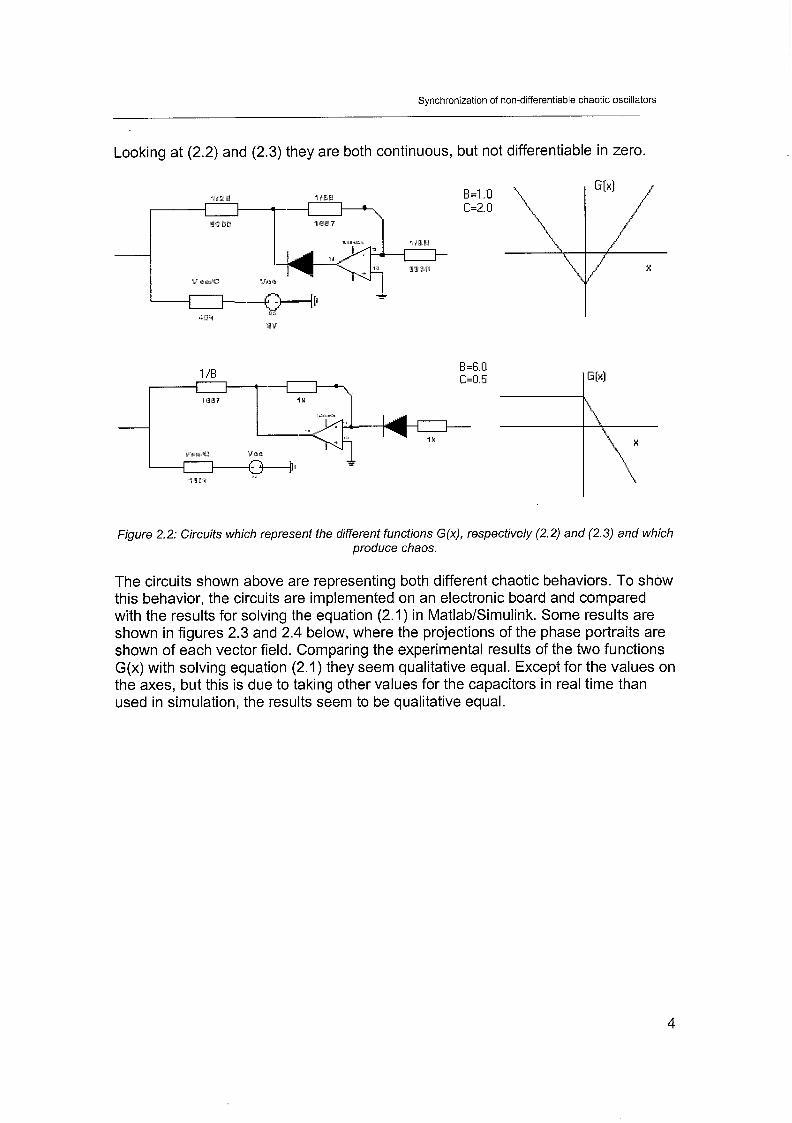
Looking at (2.2) and (2.3) they are both continuous, but not differentiable in zero.
Figure 2.2: Circuits which represent the different functions G(x), respectively (2.2) and (2.3) and which produce chaos.
The circuits shown above are representing both different chaotic behaviors. To show this behavior, the circuits are implemented on an electronic board and compared with the results for solving the equation (2.1) in MatlabISimulink. Some results are shown in figures 2.3 and 2.4 below, where the projections of the phase portraits are shown of each vector field. Comparing the experimental results of the two functions G(x) with solving equation (2.1) they seem qualitative equal. Except for the values on the axes, but this is due to taking other values for the capacitors in real time than used in simulation, the results seem to be qualitative equal.

Synchronization of non-differentiable chaotic oscillators
Figure 2.3: Phase portraits, respectively simulated (left) and experimental (right), of XI and -x2 for function G(x) = ~1x1- C .
Figure 2.4: Phase portraits, respectively simulated (left) and experimental (right), of XI and -x2 for function G(x) = - B max(x,O) + C.

Synchronization of non-differentiable chaotic oscillators
Chapter 3: Synchronization of two chaotic Sprott circuits
3.1 Introduction In the next section the stability of the Sprott circuits in the equilibrium point is checked. Then a linear state feedback controller is used to synchronize these circuits, (2.2) and (2.3), in simulation. However, now a priori knowledge of the full states is necessary. In section 3.4 the strategy of robust asymptotic synchronization is used for the two circuits, which uses only one state component to achieve asymptotically stability around zero [Z]. Section 3.5 treats synchronization by means of output feedback assuming the non-linearity to be known.
3.2 Stability of the synchronizing systems in zero To check the stability of the synchronizing systems around zero, the systems (2.1) can be written in state space form:
- XI,^ - X 2 , j
- X2 , j - ' 3 , j
(3.1 -
x3, j - -x2, j -Ax,>j + ' j(x1,j) where the subscript, j=M,S indicates the master (2.2) and slave (2.3) system. Assume that the control, which is used in the next section, is a signal that is injected into the third equation of the slave circuit. Such a signal is a coupling force between the two systems. Define ei = xi,, -xi,, . Then, the dynamics of the synchronization error can be written
as follows:
P, = -e, - Ae, + B, lx,, 1 - Cl + B2 max(x,, - el ,o) - C2 - u
By taking u = 0 it can immediately be seen that the point (el,e,,e3) = (0,0,0) is not an equilibrium point, which is the point where the stability has to be reached. So the open loop system cannot be stabilized around the origin. A control law has to be designed to make e = 0 equilibrium and achieve stability of the closed loop system.
3.3 State feedback control Here the purpose is to synchronize the two Sprott circuits by means of state feedback. This means the complete dynamics and the states e l , e, and e, of the synchronization error must be known. The systems are synchronized with a linearizing state feedback control law in which the error between master and slave becomes zero.
Synchronization of non-differentiable chaotic oscillators
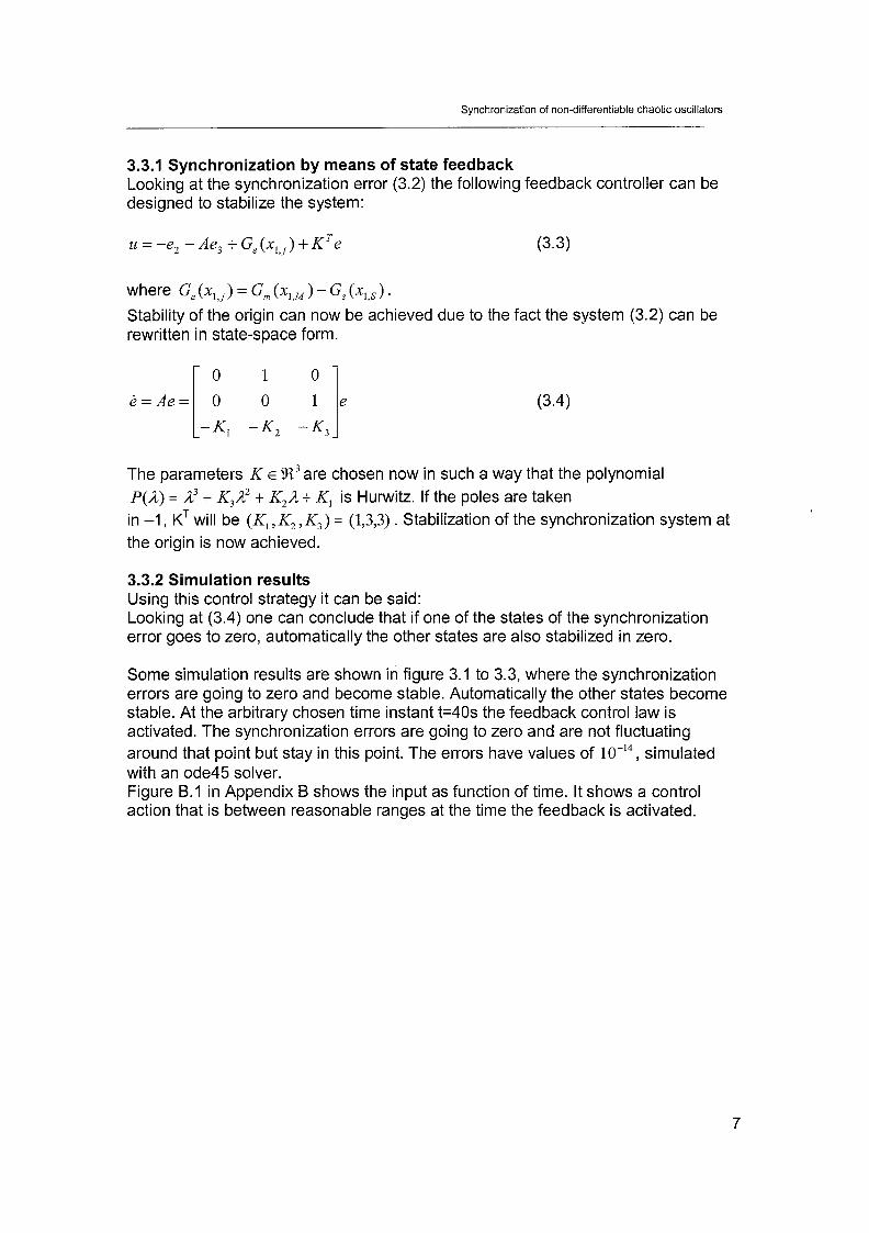
3.3.1 Synchronization by means of state feedback Looking at the synchronization error (3.2) the following feedback controller can be designed to stabilize the system:
u = -e2 - Ae, + G,(x , ,~) + ~ ' e (3.3)
where Ge ( X I , ) = Gm ( X I , , ) - Gs ( X I , , ) . Stability of the origin can now be achieved due to the fact the system (3.2) can be rewritten in state-space form.
The parameters K E !R3 are chosen now in such a way that the polynomial P(A) = A3 t +,A2 t K2A t K, is Hurwitz. If the poles are taken in -1, K~ will be (K, , K2 , K,) = (1,3,3) . Stabilization of the synchronization system at the origin is now achieved.
3.3.2 Simulation results Using this control strategy it can be said: Looking at (3.4) one can conclude that if one of the states of the synchronization error goes to zero, automatically the other states are also stabilized in zero.
Some simulation results are shown in figure 3.1 to 3.3, where the synchronization errors are going to zero and become stable. Automatically the other states become stable. At the arbitrary chosen time instant t=40s the feedback control law is activated. The synchronization errors are going to zero and are not fluctuating around that point but stay in this point. The errors have values of 10-14, simulated with an ode45 solver. Figure B.l in Appendix B shows the input as function of time. It shows a control action that is between reasonable ranges at the time the feedback is activated.

Synchronization of non-differentiable chaotic oscillators
time [s]
time [s]
Figure 3. I: Synchronization error e, of the Sprott circuits with functions G(x) (2.2) and (2.3) with full knowledge of the nonlinear system.
time [s]
time [s]
Figure 3.2: Synchronization error e, of the Sprott circuits with functions G(x) (2.2) and (2.3) with full
knowledge of the nonlinear system.

Synchronization of non-differentiable chaotic oscillators
I I
-4 I I 0 10 20 30 40 50 60 70 80 90 100
time [s]
10 20 30 40 50 60 70 80 90 100 time [s]
Figure 3.3: Synchronization error e3 of the Sprott circuits with functions G(x) (2.2) and (2.3) with full
knowledge of the nonlinear system.
However, in most practical cases the error vector e E % is not available for feedback from measurements. Therefore, the control law (3.3) cannot directly be implemented. To avoid this problem an output feedback strategy is used in the next section to achieve synchronization of the two circuits.
3.4 Output feedback control The purpose is to synchronize the two Sprott circuits by means of output feedback with the strategy described in [Z]. It means that only with the knowledge of one state component of each system full synchronization can be achieved.
3.4.1 Synchronization by means of output feedback The chaotic systems can be written in state space form.
where the subscript, j=M,S indicates the master (2.2) and slave (2.3) system. As above assume that the control is a signal that can be injected into the third equation of the slave circuit. So, also define e, = x,,, - x,,, . Then, the dynamics of the synchronization error can
be written as follows.

Synchronization of non-differentiable chaotic oscillators
el = e2
e2 = e3
e, = -e2 - Ae, + G,(x , ,~ ) -u
where Ge ( ~ 1 , j ) = Gm ( X I , , ) - Gs ( X I , , ) . The output is assumed to be given by y = h(e) = e, . The relative degree of the system (3.6) is 3. The zero dynamics is trivial and the system is feedback linearizable and controllable. The system can be completely transformed into the normal form. In order to obtain, just for completeness with regard to 121, the coordinates transformation
z = ( z l , z 2 , z , ) = D(e) = (h(e), Li h(e), L;h(e))', one should compute the Lie derivatives
of system output h(e) along f (e) , thus one has that
z1 = e l , z2 = e2 and z, = e, , so D(e) = , from where the Jacobian matrix
9@(e) = 0 1 0 is obviously nen-singular. It is possible to stabilize the system [: 1 11 around the origin. The system in canonical form is:
where Gz = Gm (xl,,) - Gs ( ~ 1 , s ) . Define: i3 = 7 ~ 2 7 ~ 3 , X I , ) ' 1
where dzl , z2 ,z3 ,x l , ) = -2, - Az, + Wxl , , z l j y = - 1
NOW let 6 = y - and O (z,u,xl,) = a(zl ,z2 ,z, ,xl,) t &. Simple algebraic manipulations yield the following expression for the transformed system:
where O (z,u,xl,) is a term which contains the non-linearity. Now define

Synchronization of non-differentiable chaotic oscillators
q = q( t ) = O (z(t),u(t),x,,(t)) In this way the system (3.9) can be rewritten in the following extended form:
where
~ ( z , ~ , u , t ) = -i2 - Ai3 t Ge(xIM ,zl) t ( y - 7)zi = (A2 - 1)z3 + Az2 - A(U- G ~ ( x , ~ , z , ) ) + Ge(xIM,zl)
1 Applying a linearizing feedback control law u = :(- 7 + K T z ) is not physically
Y realizable because it requires measurements of the states z(t) and the uncertain state 7( t ) . By using a high-gain observer, the problem of estimating z(t) and q(t) can be solved. Thus, the dynamics of the states z and 7 can be reconstructed from measurements of the output y = h(z) = z, in the following way:
where ( K , , K, , K , , K ~ ) = (16,32,24,8) are chosen such the polynomial
P@)= A4 + K ~ A ~ + K,A' +K,A + K , has all its eigenvalues in the open left half of the complex plane. The parameter L > 0 indicates the high-gain parameter. It can be interpreted as the uncertainty estimation rate and it is the unique tuning parameter. If this parameter increases, the error will decrease. The linearizing feedback control law with uncertainty estimation now becomes
where the control parameters also are chosen such that the polynomial P@)= A3 + K3A2 +K2A + K1 has all its roots located in the left-half of the complex
plane. To check the stability of the closed loop system (3.1 O), (3.11) and (3.1 2) define the error: E, = Z , - 2, i = 1,2,3 and E, = q - I j . Then the dynamics of the error is governed by:

Synchronization of non-differentiable chaotic oscillators
where @(z, q, t ) is an unknown nonlinear bounded function. Assuming that also in
the controlled form (3.1 3) z belongs to an attractor q = q(t) = @(z(t), u(t)) is a bounded function. For that reason E(z, q, t) and @(z, q, t ) are also bounded. The
matrix A(L,K,) is given by:
Because A(L,K,) has all its roots located in the left half of the complex plane, one can conclude that for infinite time E stabilizes around zero , which means the estimation error is globally asymptotically stable. The estimation error stays within a ball of radius around the origin but cannot reach the origin due to the estimation of the uncertain nonlinear term 7 and bounded function @(z, q, t ) . Exact complete synchronization is not possible. Figure 3.4 shows the synchronization phenomenon of practical complete synchronization. A disadvantage of this strategy is that high-gain observers can induce undesirable dynamic effects such as peaking phenomenon in the input due to the fact that the unknown term E(z, q, t ) has been neglected in the construction of the observer. To reduce these effects the control law can be modified by means of a saturation function. However, as we shall see below, the peaking is a non-trivial problem such that it restricts the synchronization in experiment. Another disadvantage of high-gain observers is noise amplification. Measurement errors are amplified by the observer and can have a negative effect on the stability of the system.
Figure 3.4: Geometrical interpretation of complete practical synchronization
3.4.2 Simulation results Using this control strategy the following can be concluded: Looking at (3.10) and the fact that the synchronization error is completely controllable and observable, one can conclude that if the first state of the

Synchronization of non-differentiable chaotic oscillators
synchronization error goes to zero, automatically the other states are stabilizing around zero.
Some simulation results are depicted in figures 3.5, 3.6 and 3.7. The following control parameters are used here to guarantee asymptotically stability: (K~,K,,K,,K,) = (16,32,24,8), L = 100 and (K, ,K,,K,) = (1,3,3) - r hese control parameters are chosen such that the input reaches no undesirabie
with to the resfriciion in the impiemeniaiioii. ifie iiiPcii iias a restriction of maxirntim voitage f lSV . The feedback contrailer was arbitrarily t~irned on at time instant t=40s. Choosing another time instant for activating the input only affects the amount of energy that is needed to achieve synchronization. Each initial condition results in asymptotic stabilization of the errors. The stabilization can be carried out because system (3.1 1) provides an estimated value of the output function y = h(z) = z, . Figure A. l in Appendix A shows the input u(t) , which is between reasonable ranges.
time [s] time [s]
-0 10 20 30 40 50 60 70 80 90 100 62 64 66 68 70 72 74 76 78 80 time [s] time [s]
Figure 3.5: Left: asymptotically stabilization around the origin of zl . Right: zoom in picture at the left
side.

Synchronization of non-differentiable chaotic oscillators
-4 1 I I I I I I I I I 0 10 20 30 40 50 60 70 80 90 100
time jsj
0 10 20 30 40 50 60 70 80 90 100 time [s]
-4 1 I I I I I I I I
0 10 20 30 40 50 60 TO 80 90 100 time [s]
time [s]
Figure 3.6: Left: asymptotically stabilization around the origin of z , . Right: asymptotically stabilization
around the origin of 2,.
I I I I I I I
Figure 3.7: x,, and x,, with output feedback control for synchronizing different oscillators after activation of the input.
3.5 Synchronization by means of output feedback with known non- linearify It is also possible to achieve synchronization with output feedback where the controller is used as in (3.3), and where the states are estimated by means of an high-gain observer since only measurements of the first state components are available. The stability of this strategy is not treated here because with the knowledge treated in the previous sections it is obvious this strategy results in stabilization of the synchronization errors as well. This strategy is only used in
Synchronization of non-differentiable chaotic oscillators
practice when synchronization of robust asymptotic stabilization is not working due to the restrictions in the input.

Synchronization of non-differentiable chaotic oscillators
Chapter 4: Practical implementation synchronization with state feedback and output feedback
4.7 Introduction In the previous chapter state feedback and output feedback control has been treated as a manner to synchrmize the diff3rent nonlinear chaotic Sprott circuits. In this chapter the three different manners of control synchr~nization are discussed from a practical point of view. dSpace in combination with MatlabISimulink is used to achieve this.
4.2 Experimental setup In figure 4.1 the different chaotic oscillators are shown which are described in chapter 2. Taking into account the power spectrum of the different oscillators and Shannon's theorem a sample frequency of 1000 Hz in dSpace is more than enough. The three states of each system can be measured.
Figure 4. I Practical realizations of the chaotic Sprott circuits on a board. Master G ( x ) = ~1x1 - C ,
Slave I: G ( x ) = ~ 1 x 1 - C and Slave 2: G ( x ) = - Bmax(x,O) t C
The input u has to be implemented on the slave system. To get the input u into the third equation, i3, , of the slave system, the circuits in figures 2.1 and 2.2 need to be analyzed. For a complete analysis see Appendix D. The main result of this analysis is that the synchronization error has the following structure in the canonical form:

Synchronization of non-differentiable chaotic oscillators
1 This means that y in (3.9) is - instead of -1 and
ClCZC3P2R2RAL
- ( ~ 1 ~ 2 + R2P2 + ~ $ 2 ) 1 v = Z, + G ( x ~ ~ , x I S ) , when implementing
CZP2RIR2 =' - ClC2 R, R, the
controller (3.12) in the experimental setup.
A n n t h n r n n i n t th-t h-c tn hn t-knn i n t n , 3 m - n 1 lnt t n 3 \1n iA c3t1 l r ~ t i n n nf t h e i n n 1 I+ A I In tn I I 1 1 I I I I 1 I u u I 1 I I uuvul I L r v c r v v t u o u r u l uuvl a vl rl lv 1 8 u y u r uub LW
the restricted DAC and ,436 outputs of the dSpace system (f IOV), is dividinglmultiplying the inputloutputs in MatlabISimulink with a factor two and multiplyldivide it again before the signals are entering into the slave system.
4.3 Experimen fa1 results state feedback Some experimental results with the state feedback controller, described in chapter 2, of the two chaotic oscillators, (2.2) and (2.3), are shown in the figures 3.2 to 3.5 with K1=744, K2=264 and K3=27. The controller is activated at t=3.3s.
2 4 6 8 10 12 time [s]
8 8.5 9 9.5 10 10.5 11 11.5 12 time [s]
8 u
0 2 4 6 8 10 12 time [s ]
8 8.5 9 9 5 10 105 11 115 12 time [s]
Figure 4.2: Left: synchronization error eI with state feedback control and different oscillators (2.2) and
(2.3). Right: zoom in the figure at the left side.

Synchronization of non-differentiable chaotic oscillators
I I I I I I 0 2 4 6 8 10 12
time [sj
I I I I I 0 2 4 6 8 10 12
time [s] time [s]
Figure 4.3: Left: synchronization error e, with state feedback control and different oscillators (2.2)
and (2.3). Right: synchronization error e, .
-4 1 I I I I I 0 2 4 6 8 10
time [s!
Figure 4.4: The input u activafed at t=3.3s for synchronizing different oscillators (2.2) and (2.3).

Synchronization of non-differentiable chaotic oscillators
XI m [Volts]
Figure 4.5: x,, and x,, with state feedback control for synchronizing different oscillators (2.2) and
(2.3) after activation of the controller.
When the controller is activated at t=3.3s the synchronization errors become stable. Z, stabilizes around a certain offset from zero and z, and z, are stabilized around
zero due to the fact that the state Z, is the time derivative of Z, and z, is the time
derivative of z,. A solution to reduce this offset is to put the poles further into the left half complex plane. The slave system needs then more energy to achieve smaller synchronization errors. However, this is not possible due to the fact that saturation of the input is present. The reason for this is that the used operational amplifiers can only handle a maximum voltage of f 15V. The two systems have different chaotic attractors and that is why there is a lot of control energy needed when the input is activated.
Looking at the synchronization by means of state feedback with two oscillators that have the same structure, like (2.2), but with different parameters, all the synchronization errors are stabilized around a point near zero similar as in figures 4.2 to 4.5. There is less input energy needed to achieve synchronization of all the three states. That is why the control parameters can be increased to get a synchronization error Z, very close to zero without saturation of the controller. The other two states are stabilized around zero. Experimental results are shown in the figures 4.6 to 4.9 with K1=13760, K2=1 863 and K3=75. The input is activated at t=3.3s.

Synchronization of non-differentiable chaotic oscillators
I I I I I I I I I I
0 2 4 6 8 10 12 8 8.2 8.4 8.6 8.8 9 9.2 9 4 9.6 9 8 10 L
iime jsj +:-.. r -7 L l l l l C i La,
-0 2 4 6 8 10 12 time [s]
time [s]
Figure 4.6: Left: synchronization error el with state feedback control for synchronizing identical
oscillators (2.2). Right: zoom in the figure at the left side.
0.4 3
2 0.2 - m +
- - E I e o 2 52 m 0
-0.2 -1
-0.4 0 2 4 6 8 10 12 -2
time [s] 0 2 4 6 8 10 12
time [s]
-0.5 I I I I I I 0 2 4 6 8 10 12
time [s] ' 0 2 4 6 8 10 12 time [s]
Figure 4.7: Left: synchronization error e, w m stare TeeaDacK control an0 laent~cal osc~llarors (2.2).
Right: synchronization error e, .

Synchronization of non-differentiable chaotic oscillators
time [s ]
Figure 4.8: The input u for synchronizing identical oscillators (2.2) activated at t=3.3s.
Figure 4.9: x,, and xls plotted with state feedback control for synchronizing identical oscillators (2.2) after the control is activated.
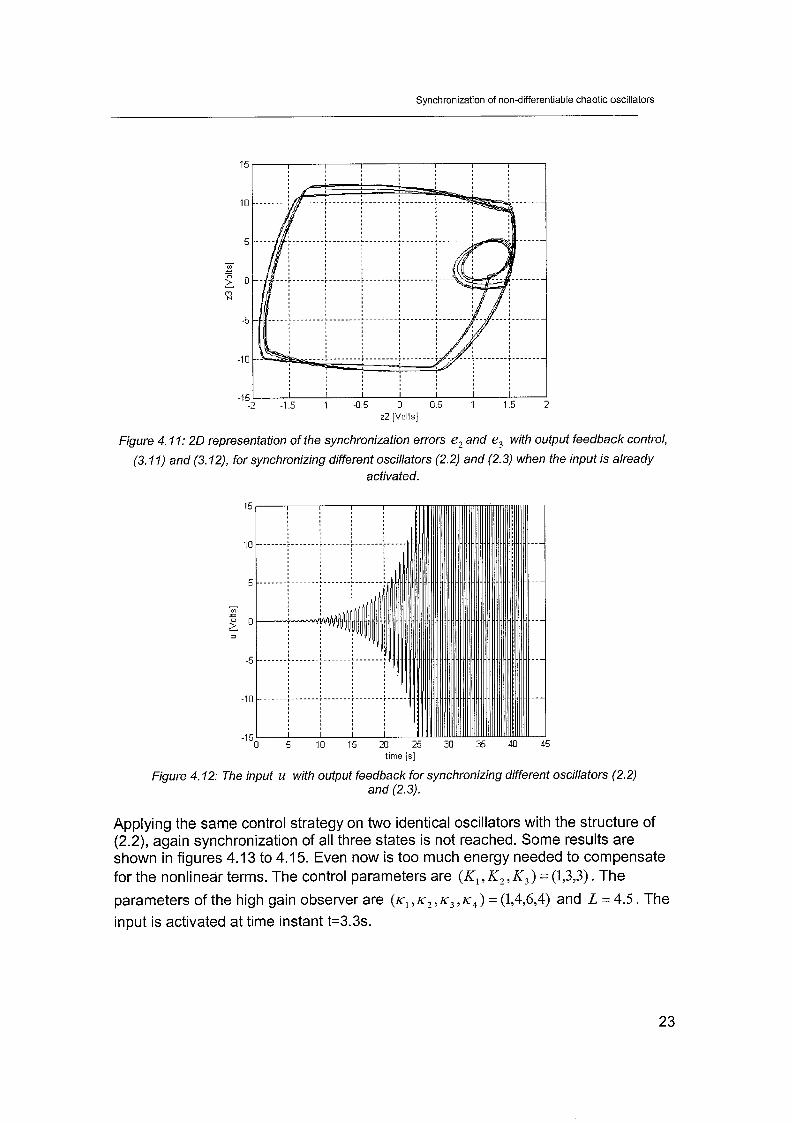
4.4 Experimental results output feedback Some experimental results, of the output feedback control law with high-gain observer described in chapter 3, are shown in the figures 4.10 to 4.12 with (K,, K,, K,) = (1,3,3). The parameters of the high gain observer are
(K~,K,,K~, K ~ ) = (1,4,6,4) and L = 4.5. The input is activated at time t=3.3s. It can be seen when looking at the synchronization errors in these figures that none of the states are stabilized. The states of the slave system are increasing drastically, but will not lead to any form of synchronization. Taking a lower value of the parameter L and increasing K1, K2 and Kg has no influence on the synchronization error. It only

Synchronization of non-differentiable chaotic oscillators
accelerates the divergence of the control signal. Increasing the high gain parameter will lead to increasing errors and saturation. In figure E.3 experimental results are shown of the input u and the synchronization errors for synchronization with different oscillators. Here the high-gain parameter is increased in time from 0 to 3.5 in steps of 0.5. Saturation appears if the high-gain parameter becomes larger than 3.0 without synchronization of the signals. A possible explanation for this is that the estimation of the unknown function 7 cannot reach all the information of the nonlinear terms f ~ : which it has t~ give a:: estimate f~:. This is due t~ the restrictim In the input. Another point that has to be taken into account is the measurement errors. Because when using a high gain observer noise amplification is present due to these errors. This noise amplification affects the synchronization error. Together with saturation of the input it is the reason for the lack of synchronization.
-20 1 I I I I I I I I I 0 5 10 15 20 25 30 35 40 45
time [s]
20 I 1 I I I I I
-20 1 I I I I I I I I
0 5 10 15 20 25 30 35 40 45 time [s]
, .--. X I slave 1 xl master
I I I I I I
I I I I I I I I I 36 37 38 39 40 41 42
tlme [s]
,
36 37 38 39 40 41 42 time [s]
--.. X I slave I
Figure 4.10: Left: synchronization error e, with output feedback control, (3.11) and
(3.12), for synchronizing different oscillators (2.2) and (2.3). Righf: zoom in the figure at the left side.
Synchronization of non-differentiable chaotic oscillators
-15 I I I I I I I
-2 -1.5 -1 -0.5 0 0 5 1 1.5 22 [Volts]
Figure 4. I I: 20 representation of the synchronization errors e, and e, with output feedback control,
(3.11) and (3.12), for synchronizing different oscillators (2.2) and (2.3) when the input is already activated.
time [s]
Figure 4.12: The input u with output feedback for synchronizing different oscillators (2.2) and (2.3).
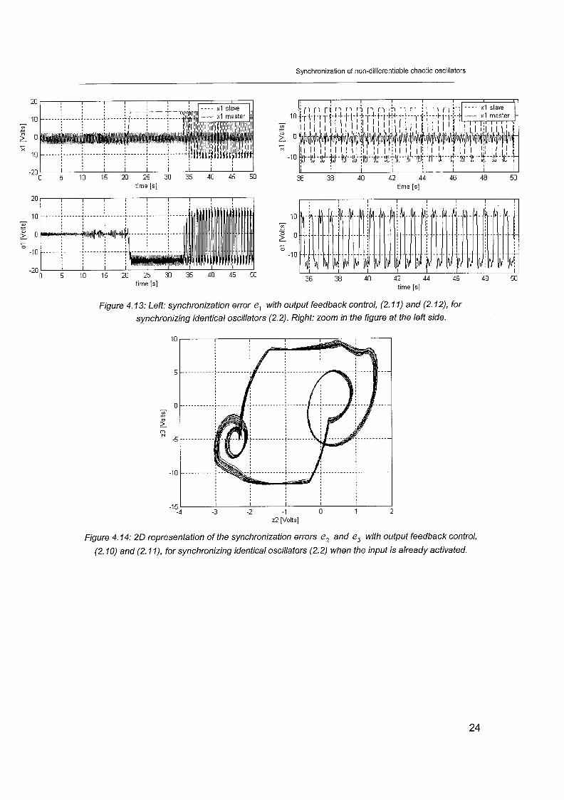
Applying the same control strategy on two identical oscillators with the structure of (2.2), again synchronization of all three states is not reached. Some results are shown in figures 4.13 to 4.1 5. Even now is too much energy needed to compensate for the nonlinear terms. The control parameters are (K , , K,, K,) = (1,3,3). The
parameters of the high gain observer are ( K , , K , , K , , K , ) = (1,4,6,4) and L = 4.5. The input is activated at time instant t=3.3s.
Synchronization of non-differentiable chaotic oscillators
time [s] time [s]
20, I I I I I I I I I I I I I I I I I I I
-20 ' I I I I I I I I I I
0 5 10 15 20 25 30 35 40 45 50 time [s] 36 38 40 42 44 46 48 50
time [s]
Figure 4.13: Left: synchronization error el with output feedback control, (2.11) and (2.12), for synchronizing identical oscillators (2.2). Right: zoom in the figure at the left side.
-5 - I U I L z2 [Volts]
Figure 4. f4: 20 representation of the syiichrcinizaiion errors- e, and e, with output fsedback coi ih' ,
(2.10) and (2. I I), for synchronizing identical oscillators (2.2) when the input is already activated.

Synchronization of non-differentiable chaotic oscillators
'-0 5 10 15 20 25 30 35 40 45 50 time [s]
Figure 4.15: The input u with output feedback for synchronizing identical oscillators (2.2).
Looking at the figures above in none of the cases synchronization is achieved by means of output feedback. A possible reason for this is the limitation in the input and the noise amplification caused by the high-gain observer. Another cause why neither form of synchronization is achieved can be the fact that during simulations the dynamics of the systems is slower than during the experiments. By using slower dynamics the state values are not fluctuating very fast in time. The controller has more time to compensate for the nonlinear terms. It is possible to reduce the dynamical speed of the systems at the same level as in the simulations by increasing the values of the capacitors. In this case it is more difficult to keep the chaotic behavior of the systems. A small increase in the control parameters will immediately result in drifting of the slave signal and result in loss of synchronization, see figure E. 1 in appendix E. Another way to look at this problem is to simulate at the same speed like in the experimental setup, see figure E.2. It can be seen that the synchronization errors are heavily fluctuating around a point near zero, although there is some kind of synchronization achieved between the two chaotic oscillators. It is concluded that synchronization cannot be reached because of saturation of the input and noise amplification caused by the high-gain observer. The fast dynamics in the systems can be the problem why robust asymptotic stabilization is not achieved. A solution to this problem is reducing the fast dynamics with another configuration of the circuits. In the configuration used here synchronizing with very slow dynamics is not possible due to drifting of the slave signal and disappearing of chaotic behavior. Another solution for this problem is making an algorithm that diminishes the effect of saturation at the moment the controller is activated. It is a relatively simple algorithm that must satisfy two conditions before it activates the input. The first condition says that the absolute difference between master and slave signals must be in a small range
I x ~ M -XIS 1 5 a 9
where a is the threshold value.
Synchronization of non-differentiable chaotic oscillators
The second condition says that the derivatives of master and slave signal must have the same sign.
sign = sign AT
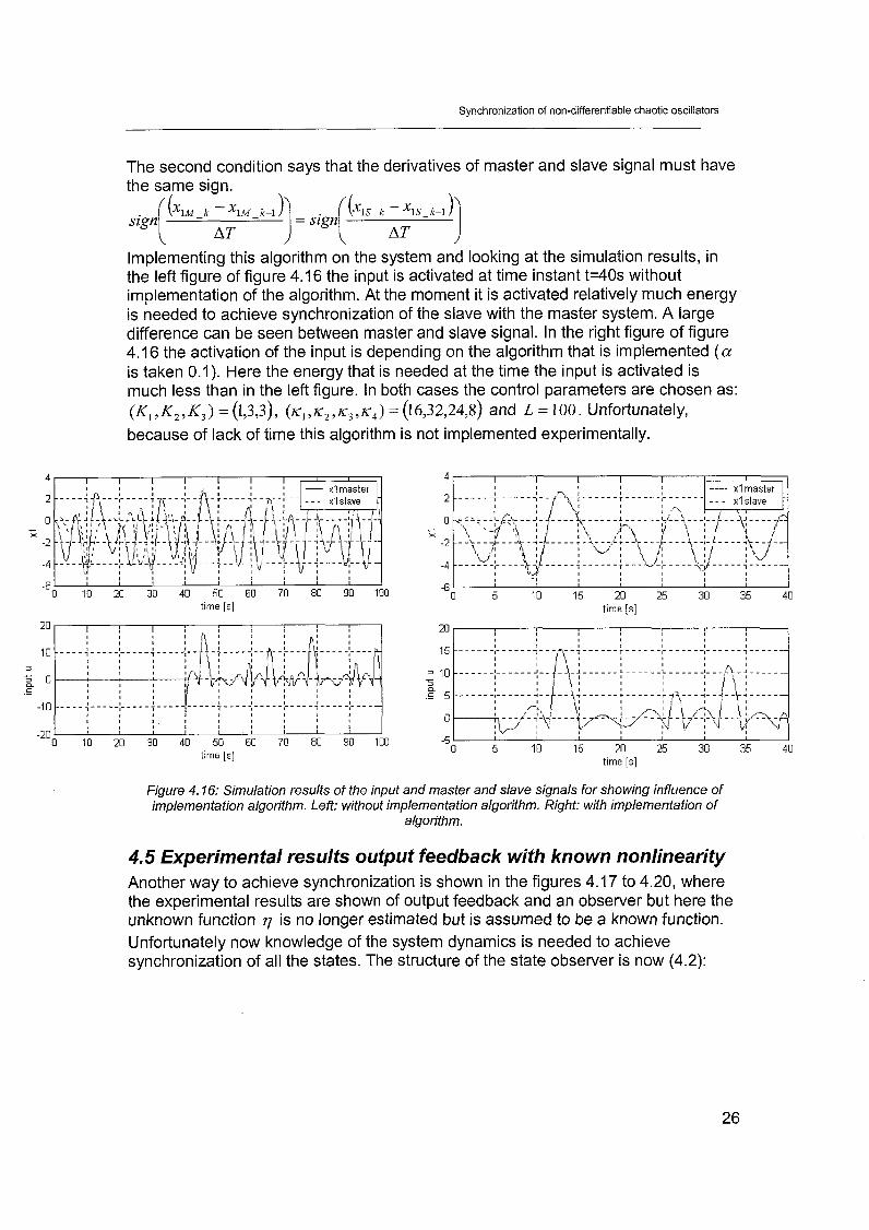
Implementing this algorithm on the system and looking at the simulation results, in the left figure of figure 4.16 the input is activated at time instant t=40s without implementation of the algorithm. At the moment it is activated relatively much energy is needed to achieve synchronization of the slave with the master system. A large difference can be seen between master and slave signal. In the right figure of figure 4.16 the activation of the input is depending on the algorithm that is implemented (a is taken 0.1). Here the energy that is needed at the time the input is activated is much less than in the left figure. In both cases the control parameters are chosen as: (K,, K,, K,) = (1,3,3), (K,, K,, K,, K , ) = (16,32,24,8) and L = 100. Unfortunately, because of lack of time this algorithm is not implemented experimentally.
I I I I I I I , ' I I
-6 I I , I I I I I I
0 10 20 30 40 50 60 70 80 90 100 tlme [s]
0 10 20 30 40 50 60 70 80 90 100 time [s]
XI master
time [s]
time [s]
Figure 4.16: Simulation results of the input and master and slave signals for showing influence of implementation algorithm. Left: without implementation algorithm. Right: with implementation of
a!go.ri?hm.
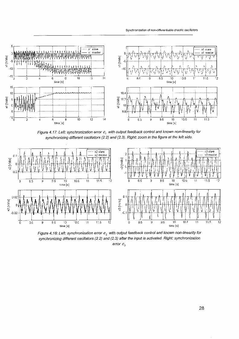
4.5 Experimental results output feedback with known nonlinearity Another way to achieve synchronization is shown in the figures 4.17 to 4.20, where the experimental results are shown of output feedback and an observer but here the unknown function 7 is no longer estimated but is assumed to be a known function. Unfortunately now knowledge of the system dynamics is needed to achieve synchronization of all the states. The structure of the state observer is now (4.2):

Synchronization of non-differentiable chaotic oscillators
with K1=0.125, K2=0.750, K3=l .5. The parameters of the high gain observer are K~ =I, K~ =3, K~ =3 and L=O. Looking at figures 4.17 to 4.20 it can be seen that the
state z, stabilizes around a certain offset from zero and z2 and z, are automatically
stabilized at zero due to the fact that z, stabilizes. Complete synchronization is not achieved because there is a certain offset in the state z, , see figure 4.17. However, it is not possible to increase one of the control parameters to get smaller synchronization errors because a small increase will immediately result in saturation of the input. Applying the designed controller with L=O to achieve synchronization is very surprising because it results in disappearance of the basic function of the observer. Due to unknown reasons, not theoretically mentioned, synchronization is still achieved.
Another point is that the experimental results in the figures mentioned are very critical. The time instant the input is activated is very important because if there is a large difference between master and slave signal or the derivatives of the signals have large values with different sign and are diverging, the input will become saturated. This is due to the fact that at this moment a lot of energy is needed to achieve synchronization. Making use of the algorithm stated before is in this case a good option.
Synchronization of non-differentiable chaotic oscillators
time is! time [s]
15 I I I I I I
-1 0 I I I I I I 0 2 4 6 8 10 12 14 8 8.5 9 9.5 10 10.5 11 11.5
time Is] time [ s ]
Figure 4.17: Left: synchronization error e, with output feedback control and known non-linearity for synchronizing different oscillators (2.2) and (2.3). Right: zoom in the figure at the left side.
time [s ] t~me [s]
0.02 0.1 - - m Ln - - ... - E 0 S O 2 (2
-0.02 -0.1
8 8.5 9 9.5 10 10.5 11 11.5 12 8 8.5 9 9.5 10 105 11 11.5 12 time [s j time [s]
Figure 4.18: Left: synchronization error e, with output feedback control and known non-linearity for synchronizing different oscillators (2.2) and (2.3) after the input is activated. Right: synchronization
error e,

Synchronization of non-differentiable chaotic oscillators
-2.5 I I I I I I I 0 2 4 6 8 10 12 14
tlme [s]
Figure 4.19: The input u with output feedback and known non-linearity for synchronizing different oscillators (2.2) and (2.3).
I I I I I
-4 -3 -2 -1 0 1 2 XI m [Volts]
Figure 4.20: x,, and x,, plotted with output feedback control and known non-linearity for syxhrcnhhg different csci!!&ors '7 I-. 21 / and (2.3) after the cc?nfrc?! inp~lf b activzted
Experimenting the same output feedback control structure on two identical oscillators with the structure of ( 2 4 , but with parameter uncertainties it can be seen in the figures 4.21 to 4.24 that all three synchronization errors are stabilized around a point near zero. By increasing roughly the control parameters, it is possible to get an error el near zero without saturation of the input. The control parameters in the control law
and the high gain observer are K1=20000, K2=1 21 3, K3=60, K , =I, K , =3, K, =3and L=36.5. The controller is activated at time instant t=2.8s.

Synchronization of non-differentiable chaotic oscillators
-6 1 I I I I
0 2 4 6 8 10 12 time [s]
-2 1 I I 1 I I I 0 2 4 6 8 10 12
time [s]
I I I I I I I I I 8 8.5 9 3.5 10 105 11 11.5 12
time [s]
I I I I I I I I I 8 8 5 9 9 5 10 105 11 115 12
tlme [s]
Figure 4.21: Right: synchronization error e, with output feedback control and known non-linearity for synchronizing identical oscillators (2.2). Left: zoom in the figure at the left side.
. -
time [sj time [s]
0 - VI - - 5 -0.02
3 -0.04
I I I I I I I I I 8 8.5 9 9.5 10 105 11 11.5 12 8 8 5 3 9 5 10 10.5 11 115 12
time [s] time [s]
Figure 422:ieft: synchronization errors e, with ouipui feedback controi and known non-iinearify for synchronizing identical oscillators (2.2) after the input is activated.
Right: synchronization error e,

Synchronization of non-differentiable chaotic oscillators
Figure 4.23: The input u with output feedback and known non-linearity for synchronizing identical
-3 -2 -1 0 1 XI m [Volts]
Figure 4.24: x,, and x,, plotted with output feedback control and known non-linearity for synchronizing identical oscillators (2.2) after activation of the controller.

Synchronization of non-differentiable chaotic oscillators
Chapter 5: Synchronization of a chain of oscillators by means of output feedback
5. I Introduction I:: this chspter the synchrcmlzatim of one master and twe s!ave Spr~ t t systems is treated. The oscillations in the slave systems need to synchronize with those of the master system. The master consists of the nonlinear function G(x) = ~ ~ 1 x 1 - Cl . Slave system 1 and 2 consist of respectively the nonlinear functions G(x) = ~ ~ 1 x 1 - C2 with slightly different parameter values and G(x) = - B3 max(x,O) t C3 . Here again the output feedback method described in chapter 3 is used to achieve synchronization of the three systems. As output function y = h(z) = z, is taken and the inputs are put in the last equation of the slave systems to get full linearizable systems. The specified form of synchronization will be as depicted in figure 5.1. Slave system 1 is the master for slave system 2.
Figure 5. I : Synchronization form with one master and two slaves
5.2 Synchronization of one master and two slave systems by means of output feedback For implementing this configuration the system needs two high-gain observers with each their own input u and tuning parameters. The structures of the different synchronization errors will be:
The subscripts M, S1 and S2 are represent respectively the Master, Slave 1 and Slave 2 system. For each of these synchronization errors a high-gain observer with input has to be designed. They are shown in equations (5.3) and (5.4).

Synchronization of non-differentiable chaotic oscillators
Exactly the same analysis to prove stability of the total system can be given as described in chapter 3. The values of the system parameters were chosen as follows: B, =I , Cl =2, B2 =O%, C, = I .60, B, =6 and C3 =0.5
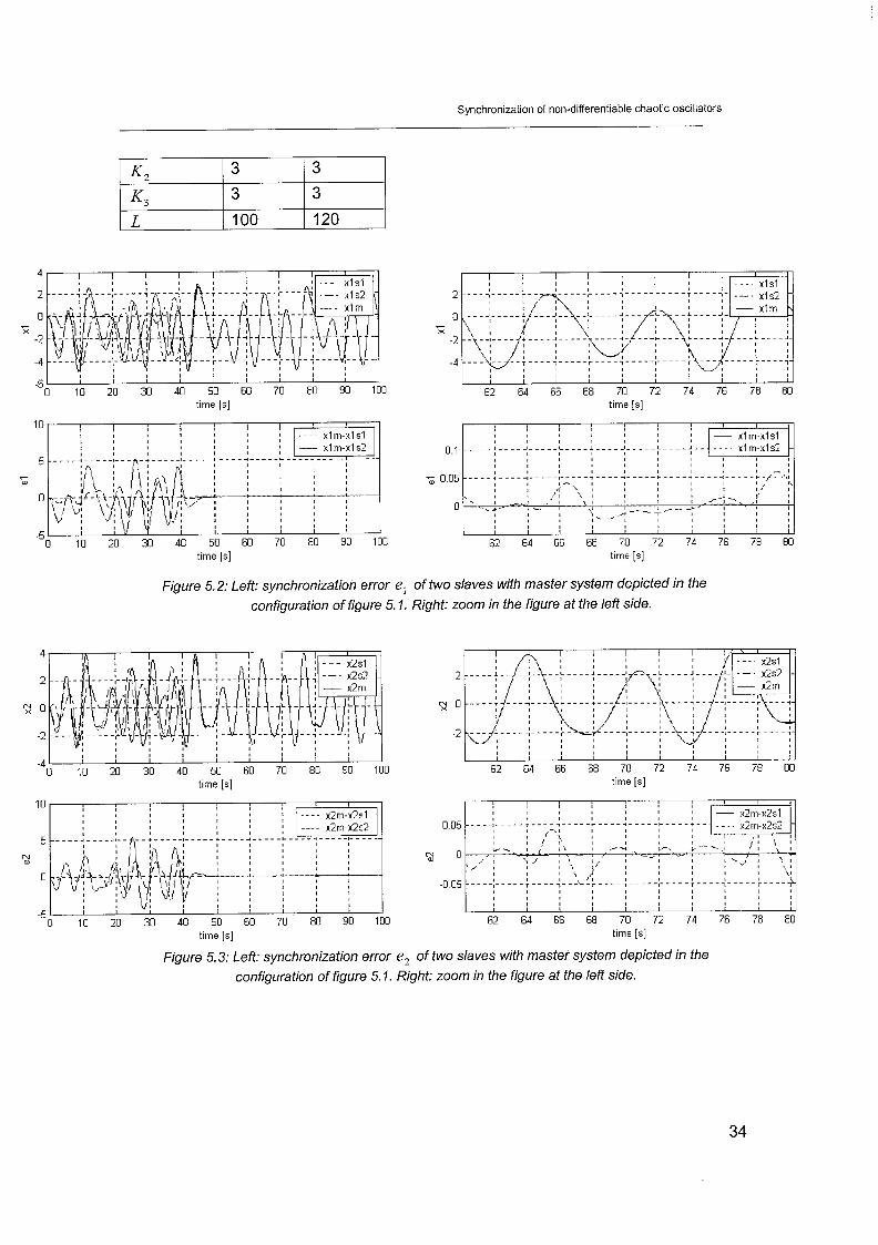
5.3 Simulation results Looking at some simulation results, figures 5.2 to 5.6, synchronization of the two slave systems and the master system is achieved. The control parameters are shown in table 5.1. At time instant t=40 the controller is activated. However, exact synchronization is not reached here, due to the estimation of the nonlinear terms 7's in the two observers. The inputs are lying between reasonable ranges with respect to the restrictions and the synchronization errors are stabilized around zero. Looking at this figures it can be seen it takes a longer time the synchronization of slave 2 with the master system is achieved compared with that of slave 1. This is because slave 1 has an error compared with the master. Due to the fact that slave 1 is the master for slave 2 the error between master and slave 2 is larger then the error between master and siave i. Therefore it t a ~ e s a ionger time synchronization is achieved between master and slave 2. Figure 5.6 illustrates the relation between the measured states of each oscillator.
table 5.1: control parameters I MS1 I S1S2
Synchronization of non-differentiable chaotic oscillators
time [s]
, I I I I I I I I I
62 64 66 68 70 72 74 76 78 80 time [s]
Figure 5.2: Left: synchronization error e, of two slaves with master system depicted in the configuration of figure 5. I . Right: zoom in the figure at the left side.
-4 1 I I I I I I I I I I 0 10 20 30 40 50 60 70 80 90 100
time [s]
I I I I I I I I I I
62 64 66 68 70 72 74 76 78 80 time [s]
time [s] tlme [s]
Figure 5.3: Left: synchronization error e, of two slaves with master system depicted in the configuration of figure 5. I . Right: zoom in the figure at the left side.

Synchronization of non-differentiable chaotic oscillators
time [s]
time [s]
Figure 5.4: Left: synchronization error e, of two slaves with master system depicted in the
configuration of figure 5. I. Right: zoom in the figure at the left side.
-6 I
0 10 20 30 40 50 60 70 80 90 100 tlme [s]
Figwe 5.5: The ir?~uf u of two s!aves with master systerr! depicted in the configur&ioon of figure 5.1.

Synchronization of non-differentiable chaotic oscillators
x l master XI master
Figure 5.6: x,, and x,_,, (left), and x,, and x,_,, (right) of two slaves with master system
depicted in the configuration of figure 5. I afier the controllers are activated.

Synchronization of non-differentiable chaotic oscillators
Chapter 6: Practical implementation synchronization of a chain of oscillators by means of output feedback
6.1 : Iratroduction lii this chapki the experimental results are sh=:l::: ~f the synchronization with one master and two slaves In series. However concluding fron the experimental results of chapter 4, robust output feedback synchronization with uncertainty estimator cannot stabilize the synchronization error in practice. This is due to the restriction in the input and the phenomenon of noise amplification. Instead of this strategy output feedback with known non-linearity, (4.2) and (4.3), is used here to achieve synchronization of these three oscillators.
6.2 Experimental results Some experimental results are shown in figure 6.1 to 6.5. The control parameters used are shown in table 6.1.
Table 6.1 : control parameters MS1 S1 S2 1 1
All the synchronization errors are stabilized, though some of them with a certain offset from zero. Remarkable is the fact the inputs are not activated at the same time. In the first case master and slave 1 system are synchronized. A few seconds !zter slave 1 and slave 2 are synchroflized. This has again to do with saturation of the input. A solution to this problem is implementing the algorithm mentioned in chapter 4. Then the input is activated at the moment the two conditions on which the algorithm is based are satisfied. When activating the inputs at the same time instant, while slave 1 is adapting to the master system, slave 2 needs to adapt to slave one. This requires too much energy, gives saturation and will not result in synchronization. To avoid this, the inputs are activated at different time instants. The controllers are activated at t=2.9s and t=4. Is. Also it can be seen here again the state z, of the second slave stabilizes with a certain offset from zero. Figure 6.4 illustrates the relation between the measured states of each oscillator. It is obvious that the synchronization between x, and x,, is better than that between x, and x,, .
Synchronization of non-differentiable chaotic oscillators
5 10 time [s]
-10 1 I I 0 5 10 15
time [s]
105 11 1 1 5 12 12.5 13 135 14 1 4 5 15 time [s]
time [s]
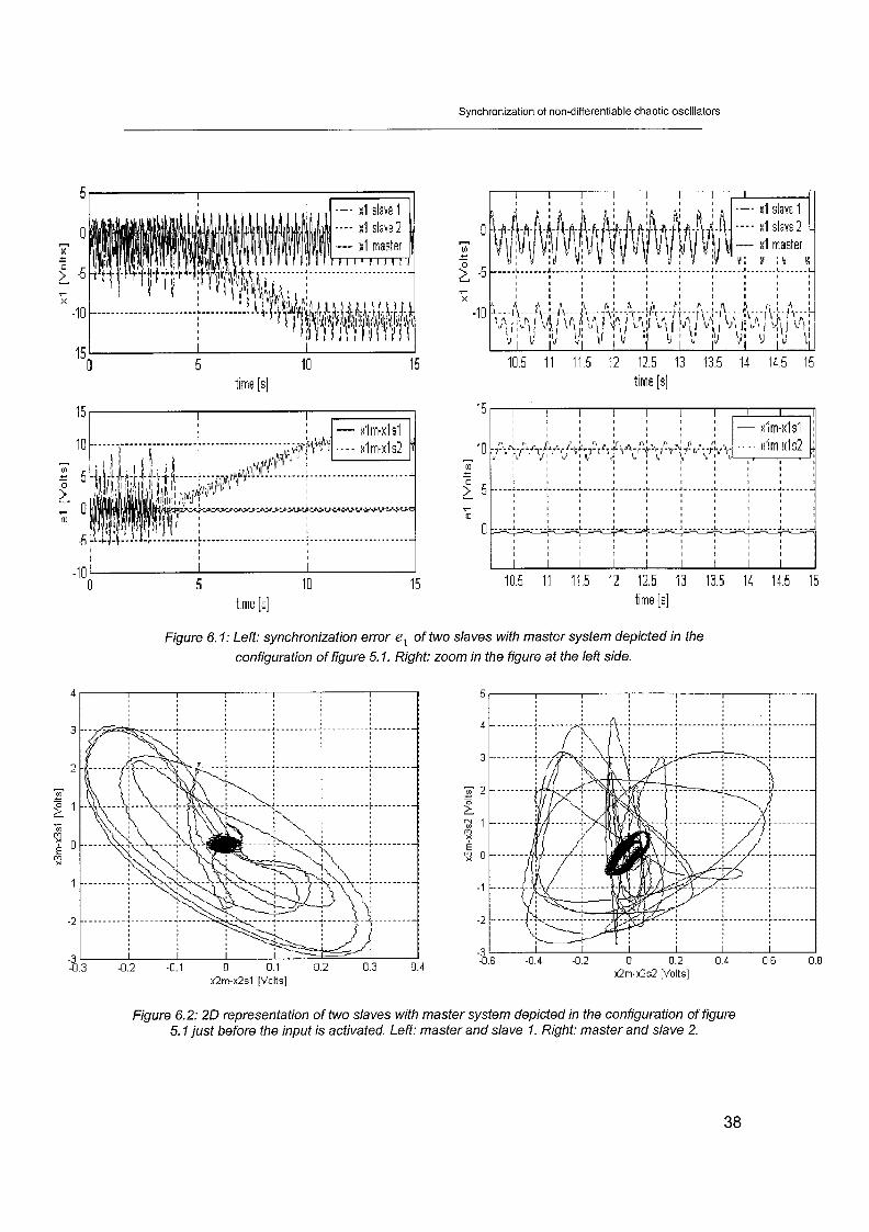
Figure 6. I : Left: synchronization error e, of two slaves with master system depicted in the
configuration of figure 5. I. Right: zoom in the figure at the left side.
x2m-x2sl [Volts] x2m-x2s2 [Volts]
Figure 6.2: 20 representation of two slaves with master system depicted in the configuration of figure 5. I just before the input is activated, Left: master and slave I . Right: master and slave 2.

Synchronization of non-differentiable chaotic oscillators
- -4 1 I I I
0 5 10 15 time [ s ]
C .- I I 0 5 10 15
time [s]
Figure 6.3: The input u of two slaves with master system depicted in the configuration of figure 5.1.
XI m [Volts] XI m [Volts]
Figure 6.4: x,, and x,-,, (left), and x,, and x, ,, [rrgnf) or two slaves wrfn master system ueplcfeu -
in the configuration of figure 5. I after the input is activated.
Synchronization of non-differentiable chaotic oscillators
Chapter 7: Synchronization of not completely linearized oscillators by means of output feedback
7. I Introduction In the previous chapters the input of the slave system was chosen in the third state equation of the nonlinear system. It is also possible to implement the inpzt in one of the other two state equations. In this chapter output feedback synchronization of one master and slave is tried to achieve with the input in the first equation of the slave system.
7.2 Synchronization of two strictly different chaotic oscillators Again synchronization by means of output feedback of the Sprott systems used in chapter 3 is treated. The synchronization error can be written as follows:
Because the output is still chosen as y = h(e) = el the relative degree of the synchronization error is r=l . This means synchronization by means of output feedback can only be achieved if the zero dynamics in equation 7.1 is minimum- phase and the tracking dynamics is stable. By defining the change of coordinates z1 = e l , v, = e, and v, = e,
z1 = qt @ +, = v,
+,= -v,- A v , ~ B,
?j= q z , q , u , t )
with 17 = V, + (y - ~ ) u
r,, 1 - C, t B, max(xl, - zl ,o) - C,
y = -1 and 6 ( z , ~ , u , t ) = i., t ( y - f)zi
v is the zero dynamics state and assume zl = el is bounded. To check the stability the state xlM has to be taken into account. One can rewrite now the zero dynamics as: i = Ar+Bz (7-3)
where r = [v, , v, , xlM , x,, , x,, I T , B = [0 - 1 0 0 o]T and for xlM z 0 A becomes

Synchronization of non-differentiable chaotic oscillators
Because this is a piecewise linear system it is not possible to investigate the eigenvalues of the separate linear systems to check the stability. Nothing can be said about the stability of the closed loop system, without further analysis. Only make use of ~ W O exact identical oscillators can prove minimum phase of the zero dynamics. See appendix C.
A=
Still trying now to achieve synchronization of some state components of the synchronization error, a high-gain observer to estimate the states and the unknown nonlinear function that is lumping the uncertainties is used.
- 0 1 0
- 1 - A B M + B ,
0 0 0
0 0 0
0 0 BM -
where K~ and K, were chosen such that the polynomial P(1) = A.' t K,A. + K, has all its roots located in the left half of the complex plane. The linearizing feedback control law with uncertainty estimation now becomes
with P(A) = A. + K , is Hurwitz.
For ulM I 0 A. becomes
7.3 Simulation results The master and slave system described above are implemented in MatlablSimulink to investigate in what senses synchronization is achieved of the three state errors. The parameter values are chosen as: K, =2, K, =I, K, =I, L =I 00. The synchronization errors of some simulation results are shown in figures 7.1, 7.2 and 7.3. The input is arbitrary activated at time instant t=40s. From these figures it is clear that only the states zl and z, achieve synchronization. The state z, is not stabilized. This kind of synchronization is called partial synchronization. However,
A = O
- 0 1 0 0
- 1 - A B , 0
0 0 1
0 0 0 0
0 0 BM - 1 -

Synchronization of non-differentiable chaotic oscillators
looking at figure 7.4 where the input u is plotted, this input is not practically realizable, because it reaches to infinite values. So experimentally the partial synchronization of these two circuits cannot be achieved. Figure 7.5 illustrates the relation between the measured states of the master and slave system.
-6 I I I t I I I I I 1 0 10 20 30 40 50 60 70 80 90 10
time [s]
1
time [s ]
time [s ]
time [s]
Figure 7. I: Left: synchronization error el with output feedback control and known non-linearity for
synchronizing different oscillators (2.2) and (2.3). Right: zoom in the figure at the left side.
-4 1 I I I I I I I I I
0 10 20 30 40 50 60 70 80 90 100 time [s]
time [s]
time [s]
time [s]
Figure 7.2: Left: synchronization error e, with output feedback control and known non-linearity for synchronizing different oscillators (2.2) and (2.3). Right: zoom in the figure at the left side.

Synchronization of non-differentiable chaotic oscillators
time [s]
time [s]
I ,, I I I I I > I I
1 :: I
-15 0 10 20 30 40 50 60 70 80 90 100
time [s]
tlme [s ]
Figure 7.3: Synchronization error e, with output feedback control and known non-linearity for
synchronizing different oscillators (2.2) and (2.3). Right: zoom in the figure at the Ieff side.
time [s]
Figure 7.4: The in,out u with output feedback and known non-linearity for synchronizing differen! oscillators (2.2) and (2.3).
Synchronization of non-differentiable chaotic oscillators
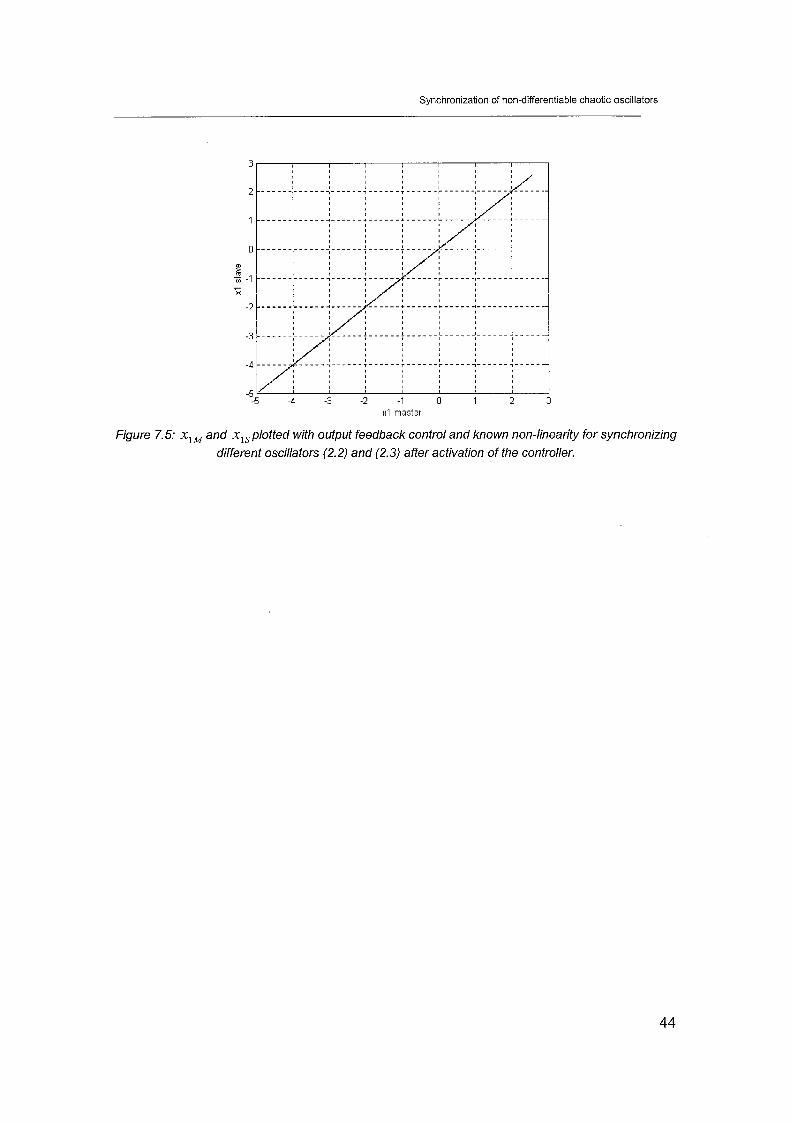
XI master
Figure 7.5: x,, and x,,plotted with output feedback control and known non-linearity for synchronizing
different oscillators (2.2) and (2.3) after activation of the controller.

Synchronization of non-differentiable chaotic oscillators
Chapter 8: conclusions and recommendations
In nature many systems present a tendency towards synchronization. In this report several types of synchronization are treated. From a control point of view it is interesting to induce synchronization in a system or a group of systems. In this report several kinds of synchronization are treated with non-differentiable chaotic oscillators in simuiailon and experiment.
The first kind of synchronization is controlled synchronization by means of state feedback. Using this kind of control all the state components need to be measured to achieve synchronization. In both cases, simulations and experiments, synchronization is achieved. However, by use of two different oscillators there is a certain offset with respect to one of the states of the synchronization error. The offset is much less by using two identical oscillators with only parameter mismatches between each other. This is due to the bounds on the input and the use of only a proportional action to achieve synchronization. Two oscillators with different structures need more control effort to reach synchronization.
A second kind of synchronization is controlled synchronization using robust asymptotic stabilization control. The main idea in dealing with the uncertainties is to lump them into a nonlinear function in such a way that the lumping function can be interpreted as a new state in an externally dynamically equivalent system. A high gain observer will give an estimate of these uncertainties. The simulation results are showing synchronization of all the states of the synchronization error; though looking at the experimental results no synchronization is reached. This is the case with different as well as identical oscillators. The reason for this is that the estimation of the nonlinear terms in the lumping function needs more control effort than is available. The dynamics in the systems is too fast to achieve robust asymptotic stabilization. Another possible reason is the noise amplification. Because there is always a measurement error present, there is noise amplification due to the used high gain observer that can result in no synchronization.
Changing the control law in such way that the uncertainty estimator is replaced by the true nonlinear terms in the third equation of the synchronization error, synchronization is achieved. Still only measurements of the first states of the systems are needed. A disadvantage of this strategy is that the non-linearity of the systems needs to be known. The remaining state components are estimated by means of the high gain observer. However, also then the problem of saturation of the input is present. By using different oscillators one of the states of the synchronization error is not stabilized at zero but with a certain offset from zero. Another point is that this synchronization is not always guaranteed. The reason is because the control effort depends on the sign of the signals of master and slave combination or the differences between master and slave signals. The algorithm mentioned in chapter 4 can be a solution to this problem.

Synchronization of non-differentiable chaotic oscillators
The synchronization of a chain of oscillators can be reached by using robust asymptotic stabilization control in simulation. In experiments however, the strategy using the known non-linearity of the systems is used to achieve synchronization.
Looking at not completely linearized systems, synchronization of all the states is not possible. Stability of this system cannot be proved yet because it is a piecewise linear system. In simulation synchronization is only achieved in the first two states of the synchronization error. Practical experiments are not possible because the input is going to infinity in simulations.
As stated before the bounds on the input plays an important role whether synchronization of non-differentiable chaotic oscillators is reached or not. Four solutions can be tried to achieve synchronization by means of robust asymptotically stability control in the future:
- The use of operational amplifiers that can handle higher voltages. This will result in the possibility of higher control efforts.
- Building another configuration of the circuits with the same chaotic structure. This structure must have the properties of reducing the speed of the dynamics with preservation of chaotic behavior.
- Implementing the algorithm mentioned in chapter 4 in an experiment that provides activating the input at the time the difference between master and slave signals is between bounded ranges. At this time the control input doesn't need much control effort to achieve synchronization of the master and slave system compared when this difference is relatively large.
- The use of another control strategy.

Synchronization of non-differentiable chaotic oscillators
References
J.C. Sprott, A new class of chaotic circuit, Physics Letters A, 266(2000), 19- 23 R. Femat, J. Alvarez-Ramirez, G Fernandez-Anaya, Adaptive synchronization of high-order chaotic systems: a feedback with low-order parametrization. Physica D, i 39(2000j, 23i-246 S. Bowong, F.M. Moukam Kakmeni, Chaos control and duration 'rime of a class of uncertain chaotic systems, Physics Letters A, 31 6(2OO3), 206-21 7 R. Femat, J. Alvarez-Ramirez, Synchronization of a class of strictly different chaotic oscillators, Physics Letters A, 236(1997), 307-31 3 R. Femat, An extension to chaos control via Lie derivatives: Fully linearizable systems, Chaos, Vol. 12, No.4, 2002 H.O. Mendez-Acosta, R. Femat, D.U. Campos-Delgado, V. Gonzalez- Alvarez, Anti-windup feedforwardlfeedback control for a class of nonlinear systems, 2003 IFAC H. Nijmeijer, A dynamical control view on synchronization, Physica D, l54(2OOl), 21 9-228 R. Femat, J. Capistran-Tobias, G. Solis-Perales, Laplace domain controllers for chaos control, Physics Letters A, 252(1999), 27-36 R. Femat, Gualberto Solis-Perales, On the chaos synchronization phenomena, Physics Letters A, 262(1999), 50-60

Synchronization of non-differentiable chaotic oscillators
Appendices
Appendix A: Simulation results output feedback control
time [s] time [s]
Figure A. I : Left: The input u to stabilize synchronization error for synchronizing different oscillators. Right: zoom in the figure at the left side
Appendix 6: Simulation results state feedback control
time [s] time [s ]
Figure B. 1: Left: The input u as function of time with function G(x) (1.2) and (1.3) with full knowledge of the nonlinear system for synchronizing different oscillators. Right: zoom in the figure af the left side
Synchronization of non-differentiable chaotic oscillators
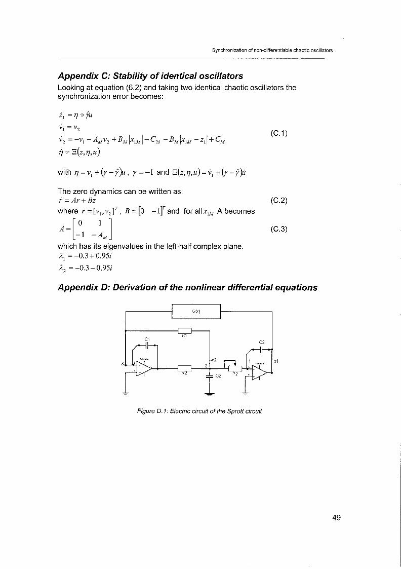
Appendix C: Stability of identical oscillators Looking at equation (6.2) and taking two identical chaotic oscillators the synchronization error becomes:
i, = q + $
V1 = v2 . ;, . = -v, - AMv2 + EM lxlM 1 0 I - C , - EM lxlM - Z , I , T r C ,
i = E(Z, q , U )
with q = v1 +(y -p)u, y = -1 and E ( z , ~ , u ) = 0, +(y-9)12
The zero dynamics can be written as: i = A r + B z (c.2) where r = [v, , v2 IT , B = [0 - 1r and for all x,, A becomes
which has its eigenvalues in the left-half complex plane. A, = -0.3 + 0.95i
A, = -0.3 - 0.9%
Appendix D: Derivation of the nonlinear differential equations
Figure D. 1: Electric circuit of the Sprott circuit

Synchronization of non-differentiable chaotic oscillators
-1 , , p y , L-3 Vee
- I' DC
Figure 0.2: G(x) = ~1x1- C
Figure 0.3: G(x) = - B max(x,O) t C
Applying Kirchoff's law in the points 1, 2 and 3 in figure D.l will lead to. For the master chaotic system, see figure D.2:
For the slave system the equations become, see figure D.3:
The synchronization error now becomes:

Synchronization of non-differentiable chaotic oscillators
Writing now the synchronization error in the canonical form the following equation appears:
. .
where G(x) = 1
The parameters that are chosen for the different resistors and capacitors are Rl = l * l o 3 Q , R2 =1*103Q, Ri3 =3.33*103C2, RI4 =1.67 * l o 3 i l , R15 =5.8*103Q,
R,, =1*103a , R,, = 1 * 1 0 3 ~ , R~~ = 1 . 6 7 * 1 0 3 ~ , R~~ =10*103i2 p2 = 0 . 7 7 * 1 0 3 ~ ,
P,, =104 .2*10 '~ , P,, =180*10'Q, Vee =15V, C, = 4 p F , C2 =194pF and
c3 = 4pF
Synchronization of non-differentiable chaotic oscillators
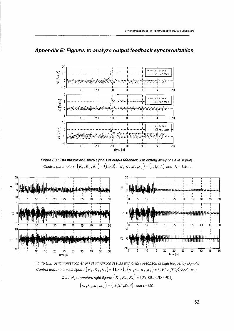
Appendix E: Figures to analyze output feedback synchronization
-;- 1 1 .........; ..-....... ......... - ?$ - x2 master
20
10 x3 slave I I
- 3 10 - C
2 0
I I I I I I 0 10 20 30 40 50 60 70
time [s ]
r r ------- ------ XI slave ......... -..-......: .--------.: ,.:.-.......:---.....-.' x l master
1 ' , /
~~(&~{t{~fi-~$h,$~&~~~~+i~fi~fij>~t~.~j.i~,j'.~~:~~:t~~~v~~v - - -
Figure E. I: The master and slave signals of output feedback with drifting away of slave signals.
Control parameters: (K, , K2 , K,) = (1,3,3), ( K , , K, , K, , K,) = (1,4,6,4) and L = 0.65.
time [s] time [s]
Figure E.2: Synchronization errors of simulation results with output feedback of high frequency signals.
Control parameters leff figure: (K, , K2 , K, ) = (1,3,3), ( K , ,K, , K , ,I;,) = (16,24,32,8) and L=60.
Control parameters right figure: (K, , K2 , K, ) = ( ~ ~ o o o , ~ ~ o o , ~ o ) ,
( K , ,K2, K3 , K, ) = (16,24,32,8) and L=150.

Synchronization of non-differentiable chaotic oscillators
5 10 15 20 25 30 35 time [s] time [s]
Figure E.3: Experimental results controller and synchronization errors when increasing fhe high-gain
parameter from 0 to 3.5. Control parameters: K I= l , K2=3, K3=3, ( K , , K ~ , K ~ , K, ) = (16,24,32,8) .