synchronized phasor applications for...
TRANSCRIPT

SYNCHRONIZED PHASOR APPLICATIONSFOR POWER GRIDS
Arun G. PhadkeVirginia Tech, USA

Catastrophic failures in power grids.
Failure mechanisms.
Countermeasures based on Wide Area Measurements(WAMS) with synchronized phasor measurements.

Presentation outline:
• Some past blackouts in North America
• Why do blackouts occur?
• Defensive strategies
• Synchronized phasor measurement systems
• Some past blackouts in North America

870 GW capacity
Thermal: 71 %Hydro: 14 %Nuclear: 13 %
Transmission:320,000 circuit-km
NORTH AMERICAN SYSTEM AT A GLANCE:
TransmissionVoltages:765, 500, 345, 138 kV

SOME MAJOR BLACKOUTS IN HISTORY:
1. North-East blackout of 1965
2. New York City blackout of 1977
4. North-East blackout of 2003
3. Western blackout of 1996
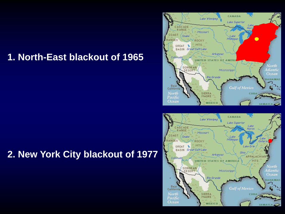
1. North-East blackout of 1965
2. New York City blackout of 1977

Buchanan
Millwood
FarragutSprainbrook
Ravenswood
Sprainbrook
Millwood
Farragut Ravenswood


3. Western blackout of 1996
4. North-East blackout of 2003

Hurricane and Earthquake Losses 1900–1989
10 times per year
Oncea year
101
100
10-1
10-2
1 10 100 1,000 10,000Loss Per event (million 1990 dollars)
HurricanesD = –0.98
EarthquakesD = –0.41
FloodsD = –0.74
ModelData
Outages
Flood Losses 1986–1992
Electric Network Outages 1984–Present
~ about 50 million people
~ about 38 years

• Why do blackouts occur?

Blackouts are Rare Events:WHY DO BLACKOUTS OCCUR ?
• Nature of the synchronous AC power system
Stressed system
Outages
Inappropriate control actions
Cascading
Loss of synchronismand blackout

• Inappropriate control actions
(1) Inappropriate protection system operations
(2) Inappropriate control system operations
(3) Inappropriate operator actions
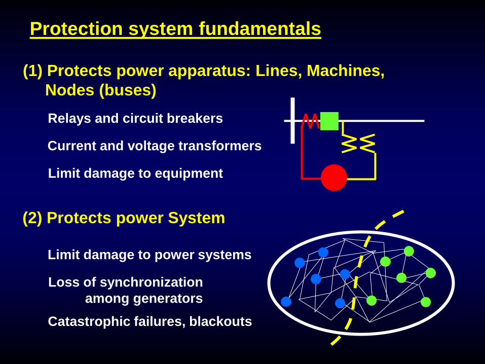
Protection system fundamentals
(1) Protects power apparatus: Lines, Machines, Nodes (buses)
(2) Protects power System
Relays and circuit breakers
Current and voltage transformers
Limit damage to equipment
Limit damage to power systems
Loss of synchronization among generators
Catastrophic failures, blackouts

Protection system fundamentals
(3) Protection system characteristics
(4) Nested protection systems
Fast response: 4-20 milliseconds
High dependability
Balanced with high security
Autonomous
X
Fast
Slow

Report Year Cases with Relay system Involvement
1984 71%1985 92%1986 83%1987 60%1988 64%
Some Statistics from NERC Reports
1986 83%
(1) Inappropriate protection system operations

NERC report for 1986 83%
Event 1 Event 2 Event 3 Event 4 Event 5 Event 6
Power System Facilities X X X XProtection Systems X X X X XSystem Monitoring X X XOperators X XOperational Planning X XSystem Reserve Response Preventive Maintenance X XLoad ReliefRestoration X X
(1) Inappropriate protection system operations

Hidden failures in a directional overcurrent relay:Transmissionline withdirectionalovercurrentrelaying
Fault
overcurrent
52aTC
+
-
Control Circuitdirectional
(1) Inappropriate protection system operations

Z2
Timer 2
T2 Z1
52a
TC
T3
Z3
Timer 3
• Hidden failures in three zone step distance relays
(1) Inappropriate protection system operations

• Concept of region of vulnerability due to hidden failures
Relay with hiddenfailure
(1) Inappropriate protection system operations

R
X
RelayCharacteristic
LineImpedance
Loss-of-field
Load increase
Power Swing
• Loadability of backup zones
(1) Inappropriate protection system operations
(2) Inappropriate control system operations
• Equipment malfunctions: excitation systems,HVDC, FACTS, SVC
• Tap changer controls
• Faulty control circuits: lockouts, etc.
• Faulty synchronizing controls

(3) Inappropriate operator actions
• New York City blackout of 1977
• August 14, 2003 blackout in North America
Usually a contributing factor in all blackout scenarios.Recent examples:
• Post-maintenance energization sequences (AEP)
• Inappropriate manual intervention (AEP)

• Defensive strategies

CAN BLACKOUTS BE MADE LESS LIKELY ?
Power system designto make stress less likely
Random events beyond control
More intelligent controls
Design of a ductile systeminstead of a brittle system
Loss of synchronismand blackout
Stressed system
Outages
Inappropriate control actions
Cascading

Power system design to make stress less likely
• These are long term solutions, well known to power system engineers:
- Sufficient generation margin
- Adequate transmission access to load centers
- Adequate reactive support
- Accurate real-time monitoring
- Security against N-k contingencies

More intelligent controls
(1) Use of wide area measurements
(2) Remedial action schemes
(3) Adaptive protection
WAMS ~ Wide Area Measurement Systems
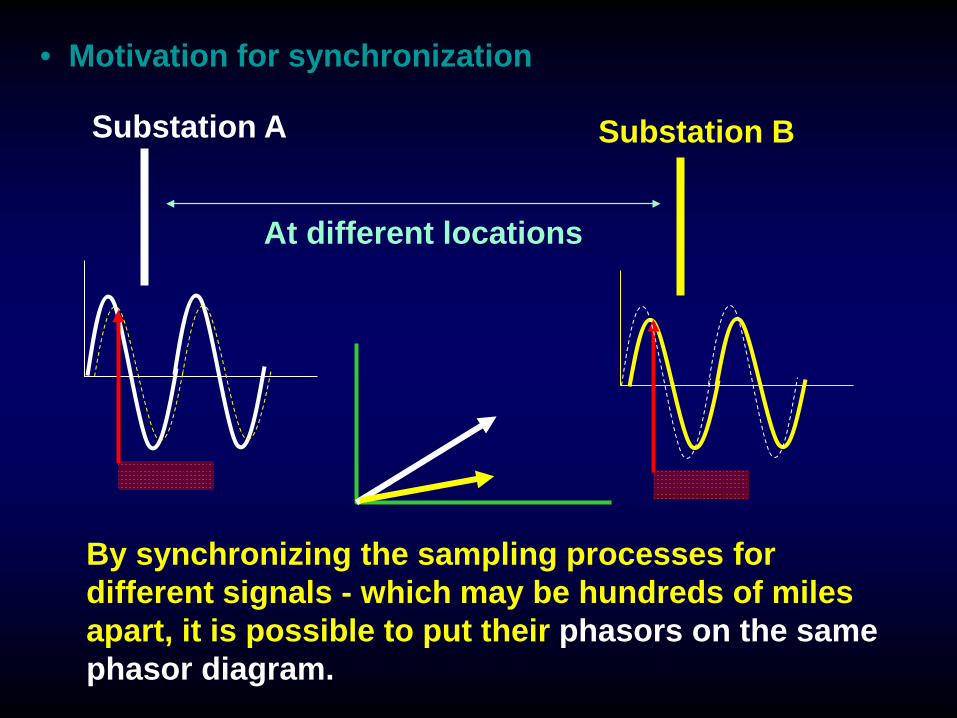
• Motivation for synchronization
By synchronizing the sampling processes fordifferent signals - which may be hundreds of milesapart, it is possible to put their phasors on the samephasor diagram.
Substation A Substation B
At different locations

• Sources for Synchronization
• Pulses• Radio• GOES• GPS

Anti-aliasingfilters
16-bitA/D conv
GPSreceiver
Phase-lockedoscillator
AnalogInputs
Phasormicro-processor
Modems
• A phasor measurement unit
(b)
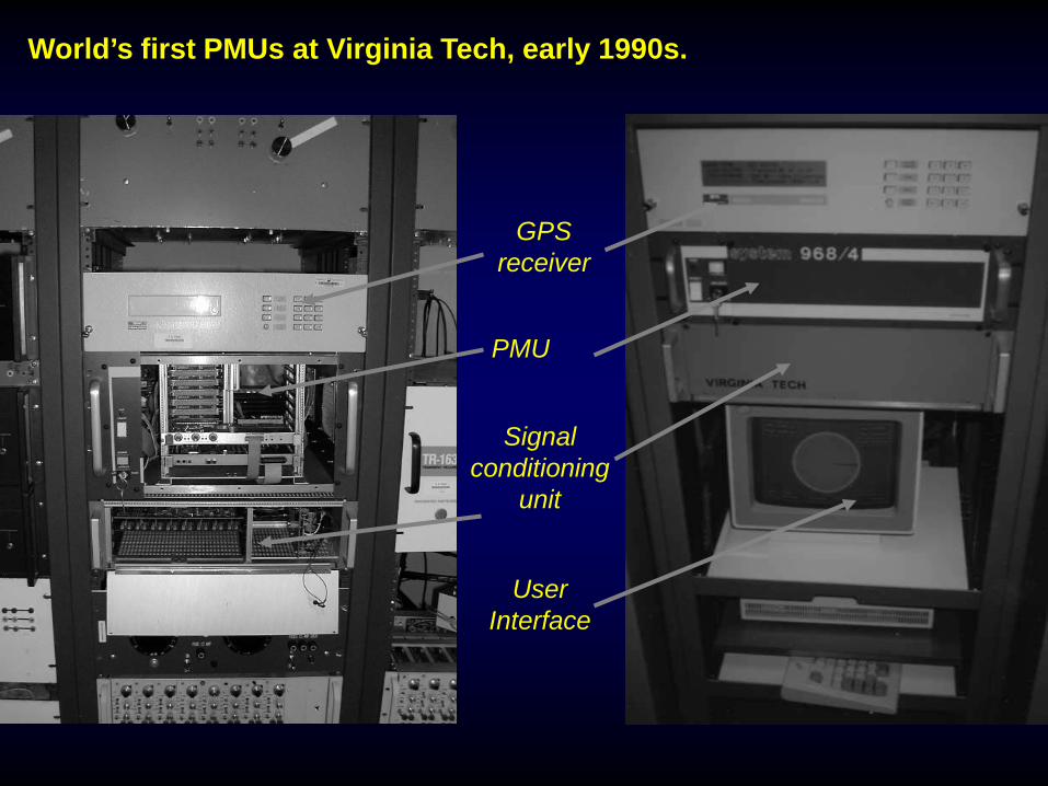
GPSreceiver
PMU
Signalconditioning
unit
UserInterface
World’s first PMUs at Virginia Tech, early 1990s.

• Introduction to phasors
θ
Real
Imag
inar
y
• The starting time defines the phase angle of the phasor.
• This is arbitrary.• However, differences between phase angles are
independent of the starting time.
θ
t=0

• State estimation with phasor measurements
Present practice
ControlCenter
Measurementsare primarilyP, Q, |E| = [Z]Measurementsare non-linearfunctions of thestate E : Z = h(E)
Measurementsare scannedand are NOTsimultaneous
Iterative weighted least square solution
[Z - Zk] = [ ]k ∆Ek∂ h∂ E

• State estimation with phasor measurements
ControlCenter
Estimation with phasorsPositive sequencePhasors are thestate vectorBecause they aresynchronized atsource, theyare simultaneousregardless ofthe speed ofcommunication
Redundancy in measurement is provided by thepositive sequence current measurements

USES OF PHASOR MEASUREMENTSADVANCED CONTROL FUNCTIONS
Present system: model based controls
ControlledDevice
Controller
Measurements

Phasor based: Feedback based control
USES OF PHASOR MEASUREMENTSADVANCED CONTROL FUNCTIONS
ControlledDevice
ControllerMeasurements

• Stabilizing a network
Georgia
Florida
Out of stepcondition
Out of steprelaysdetectincipient instability

RegionalCenter
NationalCenter
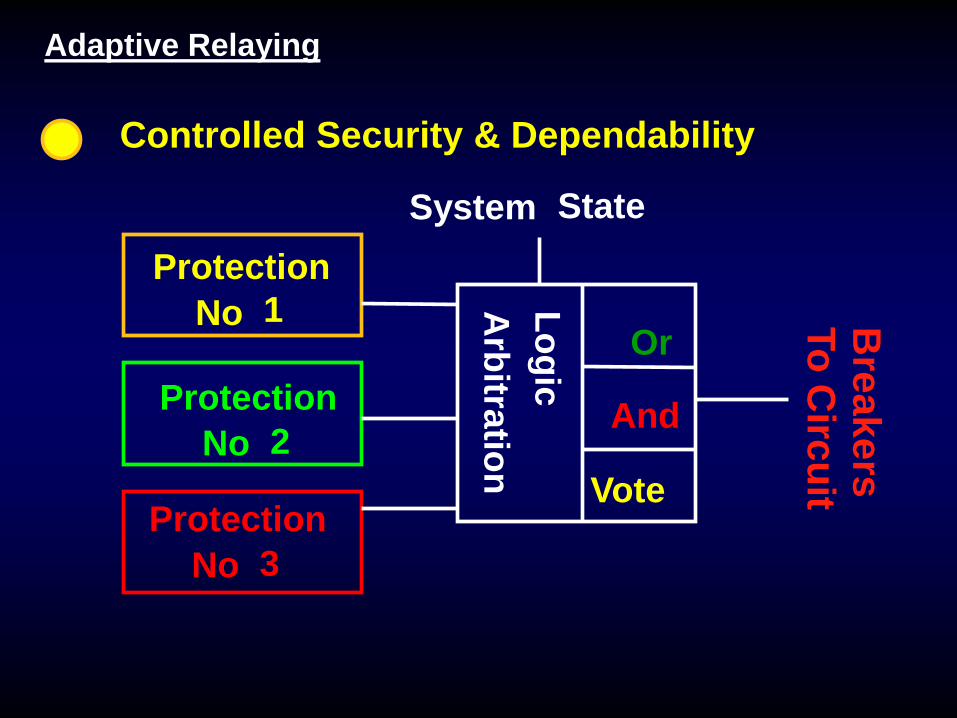
Controlled Security & Dependability
Arbitration
Logic
System State
And
Vote
ProtectionNo
ProtectionNo
ProtectionNo
1
2
3
Or
To Circuit
Breakers
Adaptive Relaying

• Intelligent islanding possibilities
(3) Real-time coherency determination
PMU data
Observation window

Design of a ductile system instead of a brittle system
DuctileSystem
BrittleSystem
Ductile and Brittle structures
Initiating event
Initiating event
• New network elements• New configurations• Renewable architectures
To achieve ductility,
Concluding remarks
•Blackouts of 2003
•Post-mortem analysis
•NERC directives
•Energy policy
•ARRA and Stimulus funding for energy systems