synchronizer - mÁquinas elÉctricas:...
TRANSCRIPT

SYN
CH
RO
NIZ
ER
The ABC’s of ‘P’ Type Motors200-SYN-97
Third EditionCopyright © August 1997
Cover photo: 'P' type induction motor rated 2950 HP, 6000 V, 880 RPM, 8 Pole, 60 Hz, 3-phase; Compressorapplication; Zone 1 hazardous area
2
The objective of this handbook is to provide a thorough and concise source of information concerning ‘p’type motors manufactured at Electric Machinery (EM). A ‘p’ type motor is a motor specifically designedto support and accommodate the proper form of ‘p’ type protection, so it can safely operate in a givenhazardous gas environment.
‘P’ type protection was developed to prevent the ingress of a potentially explosive atmosphere into theenclosure of an electric motor or generator. The primary objective for implementing this type of protectionwas to create a machine that can be operated in a potentially hazardous gas environment and satisfy theapplicable international standards; specifically, IEC (International Electrotechnical Commission) or EN(Euronorm) Standards. Once these standards are met, EM can have the motor tested and certified by anAuthorized Test Institution if desired by the customer. Although this handbook focuses on internationalstandards, comparisons are made between both international and national standards.
After extensive research and development, several design modifications and additions were required inorder to implement ‘p’ type protection. Some of these changes included special electrical and mechanicalcontrol equipment, enclosure design, and shaft seals. Electric Machinery has manufactured, tested andsold a wide range of electric motor designs equipped with ‘p’ type protection that have met thecertification requirements to ensure safe operation in the field. The horsepower rating of these machinescan range from 500 hp - 25,000 hp, for induction motors, and 500 hp - 60,000 hp, for synchronous motors,with speed ratings of 200 rpm - 3600 rpm.
Introduction to‘P’Type Motor Protection
INTR
OD
UC
TIO
N

CO
NTE
NTS
3
section page1.0 What is ‘P’ Type Motor Protection? . . . . . . . . . . . . . . . . . . . . . . . . . . . . . . . . . 42.0 Characteristics of ‘P’ Type Motor Protection . . . . . . . . . . . . . . . . . . . . . . . . . . . 5
2.1 Ex p Protection Methods . . . . . . . . . . . . . . . . . . . . . . . . . . . . . . . . . . . . . . . . . . . . . . . . . . . . . . . . . . . 52.2 Pressurization Techniques . . . . . . . . . . . . . . . . . . . . . . . . . . . . . . . . . . . . . . . . . . . . . . . . . . . . . . . . . 5
2.2.1 Leakage Compensation (LC) . . . . . . . . . . . . . . . . . . . . . . . . . . . . . . . . . . . . . . . . . . . . . . . . . 52.2.2 Continuous Circulation (CC) . . . . . . . . . . . . . . . . . . . . . . . . . . . . . . . . . . . . . . . . . . . . . . . . . 5
2.3 Purge Methods . . . . . . . . . . . . . . . . . . . . . . . . . . . . . . . . . . . . . . . . . . . . . . . . . . . . . . . . . . . . . . . . . . . 52.4 Purge Medium . . . . . . . . . . . . . . . . . . . . . . . . . . . . . . . . . . . . . . . . . . . . . . . . . . . . . . . . . . . . . . . . . . . 62.5 Ex p Motor Protection Systems . . . . . . . . . . . . . . . . . . . . . . . . . . . . . . . . . . . . . . . . . . . . . . . . . . . . . 6
2.5.1 Classification of CCF Motors . . . . . . . . . . . . . . . . . . . . . . . . . . . . . . . . . . . . . . . . . . . . . . . . . 63.0 LCA and LCF Systems . . . . . . . . . . . . . . . . . . . . . . . . . . . . . . . . . . . . . . . . . . . .8
3.1 LCA System . . . . . . . . . . . . . . . . . . . . . . . . . . . . . . . . . . . . . . . . . . . . . . . . . . . . . . . . . . . . . . . . . . . . . . 83.1.1 Sequence of Operation . . . . . . . . . . . . . . . . . . . . . . . . . . . . . . . . . . . . . . . . . . . . . . . . . . . . . . 8
3.1.1.1 Purge Sequence . . . . . . . . . . . . . . . . . . . . . . . . . . . . . . . . . . . . . . . . . . . . . . . . . . . . 83.1.1.2 Pressurization Sequence . . . . . . . . . . . . . . . . . . . . . . . . . . . . . . . . . . . . . . . . . . . . . 8
3.1.2 Control Unit (CU) . . . . . . . . . . . . . . . . . . . . . . . . . . . . . . . . . . . . . . . . . . . . . . . . . . . . . . . . . . 93.1.3 Protection Unit (PU) . . . . . . . . . . . . . . . . . . . . . . . . . . . . . . . . . . . . . . . . . . . . . . . . . . . . . . . 103.1.4 Air Control Unit (ACU) . . . . . . . . . . . . . . . . . . . . . . . . . . . . . . . . . . . . . . . . . . . . . . . . . . . . 103.1.5 Purge Air Supply . . . . . . . . . . . . . . . . . . . . . . . . . . . . . . . . . . . . . . . . . . . . . . . . . . . . . . . . . . 10
3.2 LCF System . . . . . . . . . . . . . . . . . . . . . . . . . . . . . . . . . . . . . . . . . . . . . . . . . . . . . . . . . . . . . . . . . . . . . 103.2.1 Sequence of Operation . . . . . . . . . . . . . . . . . . . . . . . . . . . . . . . . . . . . . . . . . . . . . . . . . . . . . 113.2.2 Component Description . . . . . . . . . . . . . . . . . . . . . . . . . . . . . . . . . . . . . . . . . . . . . . . . . . . . 11
4.0 Testing for ‘P’ Type Motors . . . . . . . . . . . . . . . . . . . . . . . . . . . . . . . . . . . . . . 124.1 Test Preparation . . . . . . . . . . . . . . . . . . . . . . . . . . . . . . . . . . . . . . . . . . . . . . . . . . . . . . . . . . . . . . . . . 124.2 Over-pressure Testing . . . . . . . . . . . . . . . . . . . . . . . . . . . . . . . . . . . . . . . . . . . . . . . . . . . . . . . . . . . . 124.3 Purge Test . . . . . . . . . . . . . . . . . . . . . . . . . . . . . . . . . . . . . . . . . . . . . . . . . . . . . . . . . . . . . . . . . . . . . . 13
4.3.1 Test Method . . . . . . . . . . . . . . . . . . . . . . . . . . . . . . . . . . . . . . . . . . . . . . . . . . . . . . . . . . . . . . 134.3.2 Test Criteria . . . . . . . . . . . . . . . . . . . . . . . . . . . . . . . . . . . . . . . . . . . . . . . . . . . . . . . . . . . . . . 13
4.4 Running Pressure Test . . . . . . . . . . . . . . . . . . . . . . . . . . . . . . . . . . . . . . . . . . . . . . . . . . . . . . . . . . . . 144.5 Temperature Rise Tests . . . . . . . . . . . . . . . . . . . . . . . . . . . . . . . . . . . . . . . . . . . . . . . . . . . . . . . . . . . 14
4.5.1 Heat Run . . . . . . . . . . . . . . . . . . . . . . . . . . . . . . . . . . . . . . . . . . . . . . . . . . . . . . . . . . . . . . . . . 144.5.2 Shutdown . . . . . . . . . . . . . . . . . . . . . . . . . . . . . . . . . . . . . . . . . . . . . . . . . . . . . . . . . . . . . . . . 144.5.3 Temperature Limits . . . . . . . . . . . . . . . . . . . . . . . . . . . . . . . . . . . . . . . . . . . . . . . . . . . . . . . . 14
4.5.3.1 External . . . . . . . . . . . . . . . . . . . . . . . . . . . . . . . . . . . . . . . . . . . . . . . . . . . . . . . . . . 144.5.3.2 Internal . . . . . . . . . . . . . . . . . . . . . . . . . . . . . . . . . . . . . . . . . . . . . . . . . . . . . . . . . . 14
5.0 Enclosure Designs for ‘P’ Type Motors . . . . . . . . . . . . . . . . . . . . . . . . . . . . . . 165.1 TEFV . . . . . . . . . . . . . . . . . . . . . . . . . . . . . . . . . . . . . . . . . . . . . . . . . . . . . . . . . . . . . . . . . . . . . . . . . 165.2 TEAAC . . . . . . . . . . . . . . . . . . . . . . . . . . . . . . . . . . . . . . . . . . . . . . . . . . . . . . . . . . . . . . . . . . . . . . . . 175.3 TEWAC . . . . . . . . . . . . . . . . . . . . . . . . . . . . . . . . . . . . . . . . . . . . . . . . . . . . . . . . . . . . . . . . . . . . . . . . 17
6.0 Applicable Standards . . . . . . . . . . . . . . . . . . . . . . . . . . . . . . . . . . . . . . . . . . . 186.1 International Standards . . . . . . . . . . . . . . . . . . . . . . . . . . . . . . . . . . . . . . . . . . . . . . . . . . . . . . . . . . . 18
6.1.1 Zone 0 . . . . . . . . . . . . . . . . . . . . . . . . . . . . . . . . . . . . . . . . . . . . . . . . . . . . . . . . . . . . . . . . . . . 196.1.2 Zone 1 . . . . . . . . . . . . . . . . . . . . . . . . . . . . . . . . . . . . . . . . . . . . . . . . . . . . . . . . . . . . . . . . . . . 196.1.3 Zone 2 . . . . . . . . . . . . . . . . . . . . . . . . . . . . . . . . . . . . . . . . . . . . . . . . . . . . . . . . . . . . . . . . . . . 19
6.2 National Standards . . . . . . . . . . . . . . . . . . . . . . . . . . . . . . . . . . . . . . . . . . . . . . . . . . . . . . . . . . . . . . . 196.3 Comparison of IEC and NEC Requirements for ‘P’ Type Motors . . . . . . . . . . . . . . . . . . . . . . . 19
Appendices . . . . . . . . . . . . . . . . . . . . . . . . . . . . . . . . . . . . . . . . . . . . . . . . . . 20A. Temperature Classification . . . . . . . . . . . . . . . . . . . . . . . . . . . . . . . . . . . . . . . . . . . . . . . . . . . . . . . . . 20B. Classification of Hazardous Locations . . . . . . . . . . . . . . . . . . . . . . . . . . . . . . . . . . . . . . . . . . . . . . . 20C. Methods of Explosion Protection . . . . . . . . . . . . . . . . . . . . . . . . . . . . . . . . . . . . . . . . . . . . . . . . . . . . 22D. Degree of Protection (IP Code) . . . . . . . . . . . . . . . . . . . . . . . . . . . . . . . . . . . . . . . . . . . . . . . . . . . . . . 23E. Degree of Cooling (IC Code) . . . . . . . . . . . . . . . . . . . . . . . . . . . . . . . . . . . . . . . . . . . . . . . . . . . . . . . . 23F. Comparisons of Standards Between Major Countries . . . . . . . . . . . . . . . . . . . . . . . . . . . . . . . . . . . 25G. Authorized Test Institutions in Europe . . . . . . . . . . . . . . . . . . . . . . . . . . . . . . . . . . . . . . . . . . . . . . . 26
References . . . . . . . . . . . . . . . . . . . . . . . . . . . . . . . . . . . . . . . . . . . . . . . . . . 27The Authors . . . . . . . . . . . . . . . . . . . . . . . . . . . . . . . . . . . . . . . . . . . . . . . . .28
1.0 What is‘P’Type Motor Protection ?
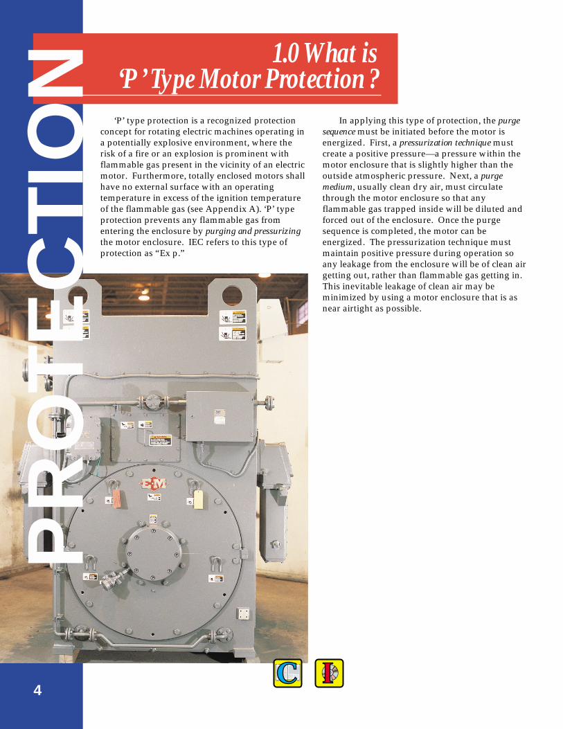
In applying this type of protection, the purgesequence must be initiated before the motor isenergized. First, a pressurization technique mustcreate a positive pressure—a pressure within themotor enclosure that is slightly higher than theoutside atmospheric pressure. Next, a purgemedium, usually clean dry air, must circulatethrough the motor enclosure so that anyflammable gas trapped inside will be diluted andforced out of the enclosure. Once the purgesequence is completed, the motor can beenergized. The pressurization technique mustmaintain positive pressure during operation soany leakage from the enclosure will be of clean airgetting out, rather than flammable gas getting in.This inevitable leakage of clean air may beminimized by using a motor enclosure that is asnear airtight as possible.
‘P’ type protection is a recognized protectionconcept for rotating electric machines operating ina potentially explosive environment, where therisk of a fire or an explosion is prominent withflammable gas present in the vicinity of an electricmotor. Furthermore, totally enclosed motors shallhave no external surface with an operatingtemperature in excess of the ignition temperatureof the flammable gas (see Appendix A). ‘P’ typeprotection prevents any flammable gas fromentering the enclosure by purging and pressurizingthe motor enclosure. IEC refers to this type ofprotection as “Ex p.”
4
PR
OTE
CTI
ON

2.0 Characteristics of ‘P‘ Type Motor Protection
CHAR
ACTE
RIST
ICS
2.2 Pressurization TechniquesThe pressurization technique shall provide the
minimum required pressure of 0.5 mbar (0.2 in. ofH2O)1 which should be achieved with the lowestpossible flow of purge medium. Therefore, thenormal working pressure is higher than 0.5 mbar.The motor enclosure must be able to withstand apressure of 1.5 times1 the normal workingpressure.
2.2.1 Leakage Compensation (LC)Before the start of a purge sequence, the
leakage compensation method will supply anample amount of purge medium to create an over-pressure and effectively purge the motorenclosure. Once purge sequence is completed, theoutlet valve is automatically closed and theleakage compensation method will supply onlyenough clean air to compensate for any leakage,and to maintain the positive pressure inside themotor enclosure (refer to Figure 2.1).
2.2.2 Continuous Circulation (CC) Before, during and after the purge sequence, a
continuous supply of clean dry air will circulatethrough the motor enclosure. The enclosurepressure is maintained by the back pressurecreated from the air outlet assembly. Thistechnique is typically used on large motorenclosures where the leakage is normally higher.
2.3 Purge MethodsIn general, the purge sequence shall initially
purge the motor with at least 5 times the volume ofthe free space in the enclosure and associatedducts.1 However, if the enclosure arrangement islarge or complex, more volume exchanges may beneeded. The time needed to purge the motor isproportional to the size of the enclosure. Typically,the purge times range from 15-30 minutes. Thereare basically three different types of purge methods:
• Compressed air (A)• Fan air (F)• Inert gas (G)
A common type of purge method used in theoperation of ‘p’ type motors is compressed air. Itis preferred over using a fan or blower becausecompressed air is usually simple to install and isreadily available at a typical motor site.
5
2.1 Ex p Protection Methods In general, when considering Ex p protection
for an enclosed electrical apparatus (see Figure 2.1),two principle questions are usually addressed:
i) Is flammable gas released or used within theenclosure?
ii) Are people needed to enter or open theenclosure while the device is operating?
The pressurization technique that will be used toachieve the desired protection is determined fromthe answers to these questions. For the motors andgenerators manufactured at Dresser-Rand/ElectricMachinery Division, “no” flammable gas is releasedwithin a machine enclosure, and “no” people needto open or enter an enclosure while a machine isoperating. Therefore, pressurization is bestachieved by using either the leakage compensation(LC) or the continuous circulation (CC) technique.When one of these two techniques is combined witha specific purge method, it will create an Ex pprotection system. The following sub sections willdescribe and compare the two pressurizationtechniques and the different purge methods.
air leakage
clean airsupply
purgeair out
apparatusenclosure
enclosureseams
outletvalve
ELECTRICAL
APPARATUS
Figure 2.1 Typical model of a ‘p’ type electrical apparatus.
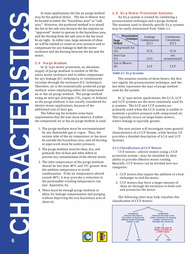
2.5 Ex p Motor Protection SystemsAn Ex p system is created by combining a
pressurization technique and a purge method.The notation used to identify specific Ex p systemsmay be easily determined from Table 2.1.
The notation consists of three letters; the firsttwo signify the pressurization technique, and thelast letter represents the type of purge methodused by the system.
In ‘p’ type motor applications, the LCA, LCFand CCF systems are the most commonly used Exp systems. The LCF and CCF systems areprimarily used when the LCA system is unable tomaintain a positive pressure with compressed air.This typically occurs on large-frame motors,where leakage is typically greater.
The next section will investigate some generalcharacteristics of a CCF System, while Section 3.0provides a detailed description of LCA and LCFSystems.
2.5.1 Classification of CCF MotorsCCF motors—electric motors using a CCF
protection system—may be classified by theirability to provide effective motor cooling.Basically, CCF motors can be divided into twocategories:
1. CCF motors that require the addition of a heatexchanger to cool the motor.
2. CCF motors that force a larger amount ofclean air through the enclosure to both cooland pressurize the motor.
The following chart may help visualize thisclassification of CCF motors:
In some applications, the fan air purge methodmay be the optimal choice. The fan or blower maybe located in either the “hazardous area” or “safearea.” However, the preferred method is to installthe fan in the safe area because the fan requires an“approved” motor to operate in the hazardous area,and the ducting from the safe area to the fan mustbe air-tight. In either case, large amounts of cleanair will be needed to create an over pressure and tocompensate for any leakage in both the motorenclosure and the ducting between the fan and themotor.
2.4 Purge MediumIn ‘p’ type motor protection, an abundant
supply of purge medium is needed to fill theentire motor enclosure and to either compensatefor any leakage (LC technique), or continuouslycirculate through the enclosure (CC technique).Therefore, air is the economically preferred purgemedium when employing either the compressedair or fan air purge method. The purge methodusing an inert gas (nitrogen, C02, argon, or helium)as the purge medium is not usually considered forelectric motor applications, because of theadditional cost of inert gas.
The following list includes some basicrequirements that the user must observe, if eitherthe compressed air or fan air purge method is used:
1. The purge medium must be uncontaminatedby any flammable gas or vapor. Thus, thesuction inlet of the air compressor or fan mustbe outside the hazardous area, and all ductingor pipe-work must be under pressure.
2. The purge medium must be clean, dry, andprimarily free of dust and other debris toprevent any contamination of the electric motor.
3. The inlet temperature of the purge mediumshould be less than 40°C and 5°C greater thanthe ambient temperature to avoidcondensation. If the air temperature shouldexceed 40°C, it may provoke a reduction inthe permissible winding temperature rise(see Appendix A).
4. There must be enough purge medium toallow for leakage compensation and purgingwithout depriving the non-hazardous area ofclean air.
Leakage ContinuousCompensation Circulation
(LC) (CC)Compressed Air(A) LCA CCAInert Gas not(G) LCG recommendedFan or Blower(F) LCF CCF
PressurizationTechniquePurge
Method
Table 2.1 Ex p Systems
6
CHAR
ACTE
RIST
ICS
CCF
IEC NEC IEC NEC
completelyremoves the heat in
the motor enclosure byadding a heat exchanger
(water or air)
completelyremoves the heat in the
motor enclosure by forcinga larger volume of airthrough the enclosure
at EM, this type ofmotor is known as
a TEFV motor

It is important to recognize that at D-R/EM,the second CCF motor is referred to as a totallyenclosed forced ventilated (TEFV) motor. Dependingon the reference source, the terminology used toidentify this type of motor may vary. The termused by D-R/EM—totally enclosed forcedventilated—is defined by NEMA (NationalElectrical Manufacturers Association). Whereas inthe United Kingdom, for example, this motor iscommonly referred to as “pressure ventilated”according to the British Standard Code of Practice(EN60 034-6).
The design of a TEFV motor provides such aneffective method of cooling that this type of motoris frequently used in safe environments, as well asthose containing a potentially hazardous gas. For amore detailed description of TEFV motors, refer toSection 5.0, Enclosure Designs for ‘P’ Type Motors.
The previous chart indicates that both types ofCCF motors are able to satisfy the requirementsestablished by either the IEC/EN or theNEC/NFPA for pressurized enclosures. Adescription and comparison of the IEC/EN andNEC/NFPA requirements is outlined in Section6.0, Applicable Standards.
There are some important decisions to be madewhen selecting a CCF motor. In order for a TEFVmotor to force large amounts of clean air throughthe enclosure, both larger ducting and fan(s) areneeded to move a sufficient amount of clean air tothe motor from a “safe area.” This should producea positive pressure and remove the heat in themotor enclosure. Otherwise, if the CCF motor canbe protected with a smaller fan and ducting system,the addition of a heat exchanger may be required toprovide the necessary degree of cooling.
The user must provide the fan(s) and ducting.It is the responsibility of the user to duct air to andfrom a safe area. However, the ducting at theoutlet may be replaced by employing a sparkarrestor. The fan(s) must be sized correctly toprovide the appropriate level of positive pressurein both the motor and the ducting.
7
Some advantages of using a CCF or TEFVmotor include: • Motor enclosures are typically easier to design
and manufacture • Less control equipment is required• TEFV motors provide motor cooling and ‘p’ type
protection—with the same system

3.1.1 Sequence of OperationAs outlined in Figure 3.2 (page 9), the LCA
System must be energized and the followingsequence of events must occur before the motor is started:
3.1.1.1 Purge Sequence
1. Turn on electrical power to the CU and theair supply to ACU.
2. Pressurize the motor enclosure above theminimum and below the maximumpressure setting.
3. Purge Boost Valve (see Figure 3.1) in the ACUwill open allowing the compressed air topurge the motor enclosure.
4. Pressure will build-up inside the motorenclosure until the Relief Valve (see Figure3.1) in the PU opens. The purge air and anyflammable gases will be flushed out of themotor enclosure through the PU.
5. The purge air flow is monitored by acalibrated Flow Switch on the Relief Valve.This switch is closed when the purge airflow has reached a predeterminedminimum.
6. The CU Purge Timer (see Figure. 3.1) isinitiated when the Flow Switch is closed andthe internal enclosure pressure is above therequired minimum.
7. The motor enclosure will continue to bepurged for a fixed amount of time. Thistime is typically 15-30 minutes.
8. After the purge time has elapsed, the PurgeBoost Valve and the Relief Valve are closed,and the Flow Switch is opened.
3.1.1.2 Pressurization Sequence
1. After the purge sequence is completed, theover-pressure is maintained by the LeakageCompensation Valve-LCV (see Figure. 3.1) inthe ACU. The LCV is set to allow enough airinto the motor enclosure to compensate forair leakage and maintain an over-pressure ofat least 0.5 mbar (0.2 inches of water).
2. The motor can now be energized.
3.0 LCAand LCF SystemsLC
A &
LC
F
8
As discussed in Section 2.0, Ex p systems can bedistinguished or classified by two primary features—the pressurization technique and the purge method.This section will focus on the two commonly usedleakage compensation systems – LCA and LCF.
3.1 LCA SystemThe LCA protection system utilizes the leakage
compensation technique with compressed air as thepurge method. As illustrated in Figure 3.1, the LCAsystem is comprised of the following components:
• Air Control Unit (ACU)• Protection Unit (PU)• Control Unit (CU)
The LCA System is capable of protecting anelectric motor located in either Zone 1 or 2 (Class I,Division 1 or 2). See Appendix B for the classificationof hazardous areas.
Advantages of LCA
1. If the motor site is equipped with compressedair, an LCA system is simple to install sinceonly small bore piping is needed instead ofthe large ducting required by the CCF system.
2. In most situations, there is a reduction inoperating costs because the leakagecompensation (LC) technique minimizes theconsumption of compressed air.
control unit
protectionunit
air controlunit
power inputsElectric Motor
compressedair in supplied
by end userair flowelectrical
Zone 1 or 2
purgeair out via
spark arrester
flowswitch
purge boost valve
purgetimer
leakage compvalve (LCV)
reliefvalve
Figure 3.1 Typical arrangement of a ‘p’ motor equipped with an LCA System.

Enclosure Pressurized AboveMinimum and Below Maximum Pressure
Purge TimerStarts
Power On toEnclosure
Alternatives(user adjustable)
Alarm & DelayedTrip of Power
Purge TimerStops
Purge Boost ValveDe-energizes to Stop Purge
Flow SwitchOpen
Relief ValveCloses
Purge Air Valve Energizes to Start Purge
Relief ValveOpens Exhaust via Spark Arrestor
Flow Switch Closesi.e. Purge Flow Proved
Alarm andTrip Power
“AlarmContact Closed”
“Pressurized”
“Purge Proved”
“Power On” or“Purge Complete”
1 2 3
X
X
X
X
On loss of pressure, 1 of 3actions must take place
(alarm is mandatory)
Denotes Option
AlarmOnly
Power On toControl Unit
Compressed Airto Air Control Unit
Figure 3.2LCA Systemautomaticsequence ofoperation.
9
3. The PU monitors the air pressure inside themotor enclosure and sends a signal to theCU if the pressure drops too low or increasestoo high. The CU has an alarm and/or tripfeature to warn users if the pressure insidethe motor enclosure is too low or too high.
3.1.2 Control Unit (CU)The control unit, CU, provides the electrical
power and control for the air control and protectionunit. The CU houses the following components:
1. Machine starting interlock2. Intrinsically safe interface unit (BRM)3. Purge timer4. Delay before trip timer (Zone 2 only)5. System status indication contacts
The control unit monitors the signals receivedfrom the protection unit by the BRM (BarrierReplacement Module). Connections are provided forthe user to indicate remote system status.
Through testing, a certifying authority willdetermine purge time, flow rates and pressureswitch set points. This information will be stampedon the nameplate of the motor. The purge timerwill be set and sealed by D-R/EM or themanufacturer of the LCA System prior toinstallation at the motor site. The “certificateholder,” D-R/EM, is authorized to set and seal thepurge timer only on motors which are an exactduplicate of one tested and certified. The purgetimer may only be reset and resealed afterconsultation with D-R/EM.
LCA
& L
CF
10
If a pressure failure occurs, it is theresponsibility of the user to choose the appropriateaction. It should reflect the zone of use and the localCode of Practice. The CU provides three types ofpressure failure action that may be selected by theuser; they are as follows:
1. Alarm and trip of motor (zero delay)2. Alarm and delayed trip of motor
(6 minutes to 25 hours)3. Alarm only (infinite delay)
The output interlock should be used to prohibitany power to the machine before purging has beencompleted and to ensure that the machine is notenergized. The control unit may be installed ineither the hazardous or safe area. The unit in thehazardous area must be placed in a flameproofenclosure with Ex d explosion protection as definedby the IEC (see Appendix C). The enclosure in thesafe area only needs to be weatherproof, with IECingress protection, IP65 (see Appendix D). Bothcontrol units contain the automatic sequencecontroller and the power interlock.
3.1.3 Protection Unit (PU)The protection unit, PU, for an LCA System
(see Figure 3.1) monitors the pressure and purgeflow at the outlet.
The PU monitors the pressure by means of lowand high pressure switches wired to produce asignal when the pressure is acceptable. A patentedRelief Valve opens if the pressure exceeds themaximum pressure setting (typically 20% less thanthe high pressure switch), and to allow the purgedgases to escape during the purging process. Acalibrated Flow Switch on the Relief Valve generates asignal when the purge flow rate exceeds theminimum. The purged gases escape into the
atmosphere through a spark arrestor designed toprevent the discharge of arcs, sparks andincandescent particles from the motor. Lightemitting diodes may be fitted on the protection unitto indicate the pressure status of the system.
3.1.4 Air Control Unit (ACU)The air control unit, ACU, regulates the air
flow during the pressurization and purgingsequences. The ACU incorporates:
1. Filter unit and drain2. Supply regulating valve and pressure gauge3. Leakage Compensation Valve (LCV) and
regulator4. Intrinsically safe purge solenoid valve 5. Purge Boost Valve
The Leakage Compensation Valve (see Figure 3.1)maintains the machine pressure at the desired level,while compensating for any leakage that may occur.The Purge Solenoid Valve will open during purging,or if the internal pressure during operation fallsbelow the required minimum. The Purge SolenoidValve will then pass a control signal to the PurgeBoost Valve (see Figure 3.1) which opens to allow afull flow of purge air into the motor enclosure. ThePurge Solenoid Valve and the Purge Boost Valve maybe integrated into a single device.
3.1.5 Purge Air SupplyConsumption of compressed air is an
important consideration when implementing anLCA System for the following reasons:
• The user must provide compressed air witha sufficient amount of supply pressure to theinlet of the ACU.
• The ACU must be sized correctly to supportthe maximum total flow rate of air throughthe motor for a given supply pressure.
The user and the Air Control Unit must be ableto accommodate the required amount ofcompressed air during purge and pressurizationcycles of a ‘p’ type motor. However, theconsumption of compressed air is directlydependent upon the enclosure design.
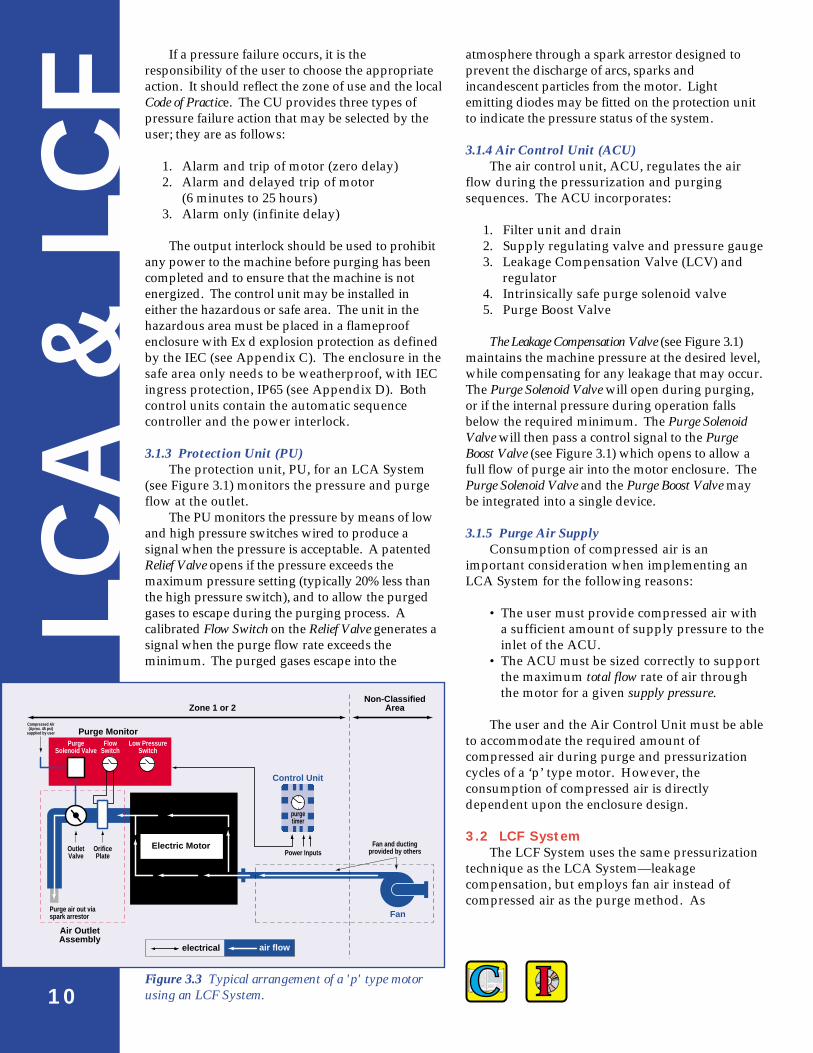
3.2 LCF SystemThe LCF System uses the same pressurization
technique as the LCA System—leakagecompensation, but employs fan air instead ofcompressed air as the purge method. As
Control Unit
Fan
Power InputsFan and ducting
provided by others
Non-ClassifiedArea
Electric Motor
Purge Monitor
Air OutletAssembly
air flowelectrical
Zone 1 or 2
FlowSwitch
PurgeSolenoid Valve
Purge air out viaspark arrestor
OutletValve
Compressed Air(Aprox. 45 psi)
supplied by user
OrificePlate
Low PressureSwitch
purgetimer
Figure 3.3 Typical arrangement of a 'p' type motorusing an LCF System.

Enclosure Pressurized
Purge Solenoid Valve On
Pneumatic Signal to Open Outlet Valve
Pressure Differential Measured Across Orifice Plate
Flow Switch Closes
Purge Timer Starts
Purge Time Completed
Purge Solenoid Valve Off
Pneumatic Signal Removed(Outlet Valve Closed)
Power On to Enclusure
Alternatives(user adjustable)
Alarm & DelayedTrip of Power
Alarm andTrip Power
“AlarmContact Closed”
“Pressurized”
“Purge Proved”
“Purge Complete”
1 2 3
X
X
X
X
On loss of pressure, 1 of 3actions must take place
(alarm is mandatory)
Denotes Option
AlarmOnly
Power On toControl Unit
Fan OnAir to Enclosure
CompressedAir to Purge
Solenoid Valve
11
3.2.2 Component DescriptionThe Control Unit in an LCF System is basically
the same component found in an LCA System. Itprovides the electrical power and control for thePurge Monitor. The Control Unit provides themachine starting interlock, intrinsically-safeinterface control, purge timer, user adjustable tripdelay timer, and system status indication contacts.Likewise, the Control Unit may be located ineither the hazardous area or the safe area.
The Air Outlet Assembly (AOA) replaces theProtection Unit used in the LCA System.
It monitors the internal pressure and measuresthe flow via the Orifice Plate at the outlet.
The PM controls the pressure by means of lowpressure switch.
described in Section 2.5, an LCF System istypically applied to large motors where the purgeand leakage rates are high. As a result, fan air ismore feasible and economical than compressedair. As shown in Figure 3.3, the LCF includes thefollowing components:
• Control Unit (CU)• Purge Monitor (PM)• Air Outlet Assembly (AOA)
3.2.1 Sequence of OperationThe flow chart shown in Figure 3.4 outlines
the sequence of operation for an LCF System.
Figure 3.4LCF Systemautomaticsequence ofoperation.

4.0 Testing for 'P' Type Motors
PU
RG
E T
EST
12
In order for a motor to be recognized as a ‘p’type motor, it requires certification from anauthorized testing institution. They will conductthe following tests:
• Over-pressure test• Purge test• Running pressure test• Temperature rise test
Once a ‘p’ type motor design has been certified,other duplicate or similar designs can acquire thesame certification without an institutionperforming the above tests.
4.1 Test PreparationFor effective explosion protection, enclosure
air-leakage must be minimized. Therefore, allenclosure sections, covers and terminal boxes(main & auxiliary) shall be completely assembledand tightened down prior to testing. Likewise, allcables or terminal leads running throughenclosure-holes shall be threaded through cableglands, and any unused enclosure-holes must beplugged to prevent air leakage. Furthermore,measures are taken to minimize the air-leakagealong shaft openings and enclosure seams byapplying specially designed seals and gaskets.
For a ‘p’ type motor employing an LCASystem, all original purge piping must be fitted onthe machine. If the ‘p’ type motor uses a CCF orLCF System, all original inlet and outlet ductingmust be assembled and connected to theenclosure. Since it is the responsibility of the userto provide the ducting, EM typically does notperform ‘p’ type tests on CCF and LCF motors.Therefore, the proceeding test descriptions willapply to a ‘p’ type motor using an LCA System.
4.2 Over-pressure TestingA flow meter and regulator are connected to a
test port on the enclosure. A pressure gauge isconnected to the enclosure to measure the internalpressure. A pressure gauge is connected to thepurge system test point. The purge outlet valve iskept closed and the compressed air valvegradually opened. The flow rate and pressuregauge reading are recorded at each significantpressure. A testing configuration for ‘p’ typemotors is shown in Figure 4.1. The following areincluded as significant pressures:
1. Low Pressure Switch set point of the ProtectionUnit: absolute minimum over-pressure (0.5mbar or 0.2 inch of H2O) per IEC 79-2: Clause12: Level of Overpressure.
2. Normal working pressure (duringpressurization): a pressure (between the High and Low Pressure Switch set points) that will occur under normal operatingconditions. A typical pressure value isapproximately 11 mbars. (4.4 inches of H2O).
3. Relief Valve set pressure: a pressure at whichthe Relief Valve in the Protection Unit will beforced open; typically, about 22 mbars (8.8inches of H2O).
4. Maximum working pressure (during theinitial purge period).
5. High Pressure Switch set point of the ProtectionUnit: typically about 30 mbars (12 inches of H2O).
6. 1.5 times the High Pressure Switch set point or1.5 times the maximum working pressurewhichever is greater. Typically, the pressureis approximately 1.5 x 30 = 45 mbar (18 inchesof H2O). As stated in IEC 79-2: Clause 4:Constructional Requirements, this test willdetermine whether or not the enclosure canwithstand the maximum over-pressurewithout causing dangerous deformation tothe enclosure.
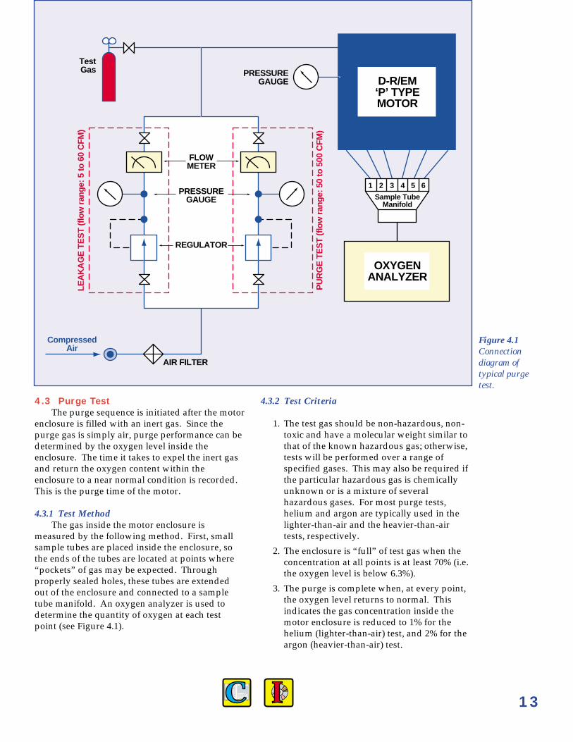
4.3 Purge TestThe purge sequence is initiated after the motor
enclosure is filled with an inert gas. Since thepurge gas is simply air, purge performance can bedetermined by the oxygen level inside theenclosure. The time it takes to expel the inert gasand return the oxygen content within theenclosure to a near normal condition is recorded.This is the purge time of the motor.
4.3.1 Test MethodThe gas inside the motor enclosure is
measured by the following method. First, smallsample tubes are placed inside the enclosure, sothe ends of the tubes are located at points where“pockets” of gas may be expected. Throughproperly sealed holes, these tubes are extendedout of the enclosure and connected to a sampletube manifold. An oxygen analyzer is used todetermine the quantity of oxygen at each testpoint (see Figure 4.1).
4.3.2 Test Criteria
1. The test gas should be non-hazardous, non-toxic and have a molecular weight similar tothat of the known hazardous gas; otherwise,tests will be performed over a range ofspecified gases. This may also be required ifthe particular hazardous gas is chemicallyunknown or is a mixture of severalhazardous gases. For most purge tests,helium and argon are typically used in thelighter-than-air and the heavier-than-airtests, respectively.
2. The enclosure is “full” of test gas when theconcentration at all points is at least 70% (i.e.the oxygen level is below 6.3%).
3. The purge is complete when, at every point,the oxygen level returns to normal. Thisindicates the gas concentration inside themotor enclosure is reduced to 1% for thehelium (lighter-than-air) test, and 2% for theargon (heavier-than-air) test.
13
FLOWMETER
CompressedAir
LEA
KA
GE
TE
ST
(flo
w r
ange
: 5 to
60
CFM
)
PU
RG
E T
ES
T (f
low
ran
ge: 5
0 to
500
CFM
)
PRESSUREGAUGE
PRESSUREGAUGE
REGULATOR
AIR FILTER
TestGas
1 2 3 4 5 6
Sample TubeManifold
D-R/EM‘P’ TYPEMOTOR
OXYGENANALYZER
Figure 4.1Connectiondiagram oftypical purgetest.

TESTI
NG
4.4 Running Pressure TestIn addition to the static over-pressure tests, a
running pressure test is also conducted at therated speed of the motor. This test is performed toensure that the minimum level of over-pressure isstill maintained, because it is not uncommon forthe internal pressure to rapidly change from onepoint to another. In fact, a negative pressure mayexist at a certain point within the enclosure;typically, the area behind a fan or blower. SeeFigure 4.2. However, this negative pressure isacceptable as long as the pressure differential fromthe fan to the enclosure is such that the pressurechanges from a negative to a positive pressure —0.5 mbar minimum. See Figure 4.3.
The motor, whether static or at rated speed,must always have an internal pressure greaterthan ambient by 0.5 mbar.
Since internal pressures may vary duringrunning conditions, the maximum and minimumover-pressure points (i.e. the Low Pressure andHigh Pressure Switch points on the PU) shall bedetermined during this stage of testing.
4.5 Temperature Rise TestsAs recommended by IEC 79-2: Clause 5:
Temperature Limits, temperature rise tests shall beconducted to verify—to the Certifying Authority—that a ‘p’ type machine will not producetemperatures exceeding the desired temperatureclassification, T-Rating (see Appendix A).
4.5.1 Heat RunA heat run test shall be conducted to simulate
full-load conditions so maximum operatingtemperatures can be determined.
Heat run test methods include:
• Three method (IEEE 115 6.2.4 Method 4)• Zero power factor (IEEE 115 6.2.3 Method 3)• Forward short circuit• Application of load machine
During all heat run tests, surface temperatureson all auxiliary terminal boxes and enclosuresmust be recorded.
4.5.2 ShutdownUpon heat run completion, the shutdown cycle
shall be initiated and all space heaters must beturned “on.” The machine shall be stopped asquickly as possible after the shutdown cycle hasbegun. Shutdown readings shall be recorded assoon as the machine is stopped. For synchronousmachines, these temperature measurements include:
• Stator winding and core surface• Field winding• Cage/end-ring assembly• Surface of space heaters• Diode wheel and rectifier assembly
(if applicable)
For induction machines, these measurements include:
• Stator windings and core surface• Rotor surface temperature• Cage temperature• Surface of space heaters
4.5.3 Temperature LimitsIf a temperature reading, during or after a
heat run, exceeds the temperature classification ofthe motor, the resulting action shall depend on thelocation of the reading; specifically, internal orexternal to the motor enclosure.
4.5.3.1 ExternalAccording to IEC standards, an electric
apparatus cannot have an ignition source in directcontact with a hazardous gas environment.Therefore, the enclosure surface or auxiliarydevices of a motor shall have no external surfacetemperature exceeding the allowable T-Rating.
4.5.3.2 InternalIf, during or after a heat run, a temperature
reading within the enclosure exceeds the machine’sT-Rating, the temperature should be monitoredand the time recorded for it to fall below the T-Rating once the motor has been shutdown. Sincethe “hot spot” is located within the pressurizedmotor enclosure, a warning plate shall be mountedonto all access covers stating the minimum amountof time before access into the enclosure can occurafter the motor has been shutdown.14
Figure 4.2 Static Overpressure in a ‘P’ Type Motorwhile running.
AfterFan
BeforeFan
Normal WorkingOverpressure
approx. 11 mbar
0.5 mbar(IEC min.)
AtmosphericPressure CoolerA B C D E A

PROTECTIONUNIT
ROTOR SHAFTSHAFT
COOLING AIR FLOWPURGE AIR FLOW
WATER-AIR HEAT EXCHANGER
EXCITERROTATINGRECTIFIER
TEWACENCLOSURE
STATOR
PURGEPIPING
AIRCONTROLUNIT
A
B
C
D
E
15
Figure 4.3 ‘P’ Type Synchronous Motor 2600 HP, 333rpm, 18 pole, 50Hz, 3ø; Reciprocating Compressorapplication; Zone 2 hazardous area.

5.0 Enclosure Designs for‘P’Type Motors
EN
CLO
SU
RES
16
The enclosure design of a ‘p’ type motor shallfacilitate two important functions—an effectivedegree of:
• Ingress Protection (IP)• Cooling
In general, all the motors designed andmanufactured at Electric Machinery Division arefurnished with a NEMA approved enclosurewhich inherently provides a degree of ingressprotection and cooling.
The degree of cooling of an enclosure, accordingto IEC Publication 34-6: Rotating Electric Machinery:Part 6: Methods of Cooling Rotating Machines, shouldbe classified under the International Cooling (IC)Code. Refer to Appendix E for further information.As shown in Table 5.1, an equivalent IC Codecorresponds to all NEMA enclosures.
In addition, the enclosure of a ‘p’ type motorshall be selected with a degree of ingressprotection that complies with the constructionrequirements suggested in IEC 79-2: Clause 4:Constructional Requirements. The enclosure shouldhave a degree of protection of at least IP4X. Asdepicted in Table 5.1, NEMA TEFV, TEAAC, andTEWAC enclosures are recommended for ‘p’ typemotor applications, but only TEAAC and TEWACenclosures are applicable for those ‘p’ type motorsemploying a LCA or LCF System.
By definition, an IP rating of IP4X means thatthe enclosure must be designed to stop the ingressof solid objects greater than 1mm. Refer toAppendix D for further information.
The following three sections will describe theNEMA enclosures manufactured at D-R/EMDcapable of providing ‘p’ type protection. The lastsection will briefly describe the enclosuremodifications that are typically applied to the 'p'type motors manufactured at EM.
5.1 TEFV - Totally Enclosed ForcedVentilated
As shown in Figure 5.1, a totally enclosedforced ventilated machine is characterized byprohibiting the exchange of internal air and the airoutside the enclosure, when inlet and outlet pipesor ducts are connected to machine openings.Totally enclosed forced ventilated machines maybe self-ventilated (air circulated by meansassociated with the machine), or forced-ventilated(air circulated by means external to and not a partof the machine). A unique feature of a TEFVmotor is its inherent ability to provide ‘p’ typeprotection as a consequence of cooling themotor—refer to section 2.5.
Table 5.1 IC & IP Codes for NEMA Enclosures
NEMA ENCLOSURE DESIGNATION IC Code IC Code IP Code +
complete simplified
OPEN Open Guard IC 0A1 IC 01 IP 00DP Drip-proof IC 0A1 IC 01 IP 12DPG Drip-proof, Guarded IC 0A1 IC 01 IP 22WPI Weather Protected, Type I IC 0A1 IC 01 IPW 23WPII Weather Protected, Type II IC 0A1 IC 01 IPW 24TEFV* Totally Enclosed Forced Ventilated IC 3A7 IC 37 IP 44TEWAC** Totally Enclosed Water-to-Air Cooled IC 8A1W7 IC 81W IP 54TEAAC** Totally Enclosed Air-to-Air Cooled IC 6A1A6 IC 616 IP 54
+ IP Code is the guaranteed minimum degree of ingress protection* TEFV provides ‘p’ type protection via continuous circulation using a fan** acceptable NEMA enclosures for ‘p’ type motors equipped with a LCA System

Figure 5.2 TEAAC enclosure design with motor driven fan
AIR IN
AIR OUT
AIR IN
Figure 5.3 TEWAC enclosure design
Figure 5.4 ‘P’ Type Induction Motor
Figure 5.1 TEFV enclosure design
17
5.2 TEAAC - Totally EnclosedAir-to-Air Cooled
As shown in Figure 5.2 a totally enclosed air-to-air cooled machine is a totally enclosed machine,which is cooled by circulating the internal airthrough a heat exchanger which, in turn, is cooledby circulating external air. The machine isequipped with an air-to-air heat exchanger forcooling the internal air, and fans for circulating theinternal and external air. The fans may or may notutilize the rotor shaft, and the fan or fans circulatingthe external air must be external to the enclosingpart or parts.
The TEAAC motor enclosure shown in Figure5.2 is equipped with an auxiliary motor driven fanto circulate the external air.
5.3 TEWAC - Totally Enclosed Water-to-Air Cooled
As shown in Figure 5.3 totally enclosed water-to-air cooled machine is a totally enclosed machinewhich is cooled by circulating air which, in turn, iscooled by circulating water. The motor enclosure isequipped with a watercooled heat exchanger forcooling the internal air, and a fan or fans, which maybe attached to the rotor shaft or separate, forcirculating the internal air.
A ‘p’ type induction motor is shown in Figure5.4. In this TEWAC enclosure design, appropriatemodifications have been made to include a LCA system.
CONTROLUNIT(CU)
AIRCONTROL
UNIT(ACU)
PROTECTIONUNIT(PU)

Item IEC 79-2/EN50016 NEC/NFPA(496)
Minimum operating 0.5 mbar 0.1” inches H2Oover-pressure (0.2 of inches H2O) (0.25 mbar)
Minimum purging 5 x volume 10 x volume
Maximum external ≤ ignition ≥ 80% ofsurface temperature temperature ignition temperature
Marking Minimum press Minimum purging timeMinimum flowInternal volumeMinimum purging volume
Table 6.2 Comparison of IEC/EN and NEC/NFPA requirements for ‘p’ type motors [6].
6.0 Applicable StandardsSTA
ND
AR
DS
18
In order to operate rotating electric machinery ina hazardous environment, standards have beenestablished by organizations and countriesthroughout the world. The standards commonlyrecognized are those established by the InternationalElectrotechnical Commission (IEC). The IEC wasfounded in 1906 to help coordinate and unifynational electrotechnical standards. In the UnitedStates, the National Electric Code (NEC) and NationalFire Protection Association (NFPA) have developedguidelines for ‘p’ type protection. A comparisontable of the standards followed by other majorcountries is shown in Appendix F.
The following sections will describe theapplication of the primary international and nationalstandards for a given hazardous gas/vapor location.International standards classify hazardous gas areasinto zones. In the United States, the NEC classifieshazardous locations into classes, where hazardousgas/vapor areas are defined as a Class I area. Todescribe the frequency of a particular hazardousarea, each class is subdivided into divisions. For a gasand vapor classification (i.e. Class I), a comparisonbetween the applicable international and nationalstandards is shown in Table 6.1.
Refer to Appendix B for a complete definitionand comparison of the classification of hazardousgas areas.
6.1 International StandardsApproximately 40 countries worldwide,
including the United States, Canada and manyEuropean countries, recognize IEC Standards asan acceptable criteria to manufacture an electricalapparatus for operation in a hazardous gasatmosphere. Specifically, the electrical deviceshould be built according to IEC Publication 79:Electrical Apparatus for Explosive Gas Atmospheres.This standard is subdivided into several parts inwhich each part defines a particular explosionprotection method.
In Europe, CENELEC (European Committee forElectrotechnical Standardization) has developedexplosion protection standards based upon theIEC called Euronorm (EN) Standards, specifically,EN50. The subsequent sections describe the IECstandards that Dresser-Rand/Electric Machineryfollows and practices.
Table 6.1 Gas and vapor classification.
IEC/CENELEC or IEC/EN NEC/NFPA
May exist continuously May exist continuouslyZone 0 under normal operating Class I or periodically under
conditions Div.1 normal operatingconditions
Zone 1 May exist periodically undernormal operating conditions
Zone 2 May exist under abnormal or Class I May exist under abnormalaccidental conditions Div.2 or accidental conditions

19
6.1.1 Zone 0 (Class I, Division 1)According to IEC recommendation,10 the
operation of rotating-electric machines isprohibited in Zone 0 hazardous areas. Therefore,D-R/EM does not manufacture ‘p’ type motors foruse in Zone 0 hazardous areas.
6.1.2 Zone 1 (Class I, Division 1)In Europe, an electric motor in a Zone 1 area
may be totally enclosed and pressurized to keepthe flammable gases out. In this zone, D-R/EMcan build a ‘p’ type machine according to IECPublication 79-2: Electrical Apparatus forExplosive Gas Atmospheres, Part 2: ElectricalApparatus-Type of Protection ‘P’ or EN50 016.These types of machines usually requirecertification from a certifying authority, such asSira Certification Services (SCS) or British ApprovalService for Electrical Equipment in FlammableAtmospheres (BASEEFA). Additional authorizedtest houses in Europe are listed in Appendix G.
An increased safety (type ‘e’) machine mayoperate in a Zone 1 hazardous area. However, theUK Department of Energy recommends that type ‘e’machines with a voltage rating above 3kV shoulduse ‘p’ type protection.7 The standards outlinedfor a type ‘e’ machine are IEC 79-7 and EN50 019.
6.1.3 Zone 2 (Class I, Division 2)In Europe, a type ‘e’ and a non-incendive or
non-sparking (type ‘n’) electric machine mayoperate in a Zone 2 region. Type ‘n’ machines witha voltage rating above 11 kV should use ‘p’ typeprotection as recommended by the UK Departmentof Energy. 7 The IEC 79-15 is the standarddescribing this type of protection. Currently, theequivalent EN standard is in draft form.
6.2 National StandardsStandards in the United States have been
established by the National Electrical Code (NEC) andNational Fire Protection Association (NFPA) to ensurethe safe operation and installation of electricalequipment in hazardous areas. For a completedescription of the motor and generator standards,refer to Articles 500-503 of the NEC-NFPA 70 4, andthe NFPA 496 Standard: “Purged and PressurizedEnclosures for Electrical Equipment.5”
6.3 Comparison of IEC and NECRequirements for ‘P’ Type Motors
The motor manufacturer, D-R/EM, and theuser must follow the requirements stated by theapplicable standard to ensure safe motoroperation. This section is focused on therequirements associated with the standardsmentioned in Sections 6.1 and 6.2. A comparisonof IEC/Euronorm and NEC/NFPA requirementsfor ‘p’ type motors is illustrated in Table 6.2.
These requirements are the basis for the ‘p’type motor test outlined in Section 4.0. After amotor successfully completes this testing, it can beofficially certified a ‘p’ type motor; thus assuringthe user safe motor operation in the declaredhazardous gas environment.
Even though a ‘p’ type motor has been testedand certified, the motor should be furnished withappropriate control equipment to ensure that theoperating requirements of the applicable standardare achieved and maintained. For example, theprotection system may need to operateautomatically (a requirement of the CENELECpressurization standard-EN50 016); hence,pressure switches or transducers are normallyprovided, interconnected with electrical, electronicor pneumatic controls. If the motor fails tooperate according to the suggested requirements,some form of alarm or trip must be initiated.
P Type Induction Motor with TEWAC enclosure.

20
AppendicesA
PPEN
DIC
ES
A. Temperature ClassificationThe Temperature Classification or “T” rating
for electric machinery has been uniformlyaccepted throughout the world. The “T” ratings,shown in Table A.1 are used to represent themaximum operating temperatures on the surfaceof the equipment.8 This temperature should notexceed the ignition temperature of thesurrounding atmosphere. These values are basedon a 40°C (104°F) ambient temperature.
Table A.1 Maximum Surface Temperature Classification
Max. Temp. “T” Rating*Centigrade (°C) Fahrenheit (°F) IEC/NEC
450 842 T1300 572 T2200 392 T3135 275 T4100 212 T585 185 T6
* The temperature classification is furthersubdivided in North America— see Table 500-3(b) of NFPA 70, NEC.
IEC*
Zone 10: A zone in which an explosive dustatmosphere is present continuously orfor extended periods of time.
Zone 11: A zone in which there is a likelihood thatexplosive atmospheres may occur forshort periods due to unsettled dustlayers.
* The Europeans (CENELEC), to date, have not yetproduced a standard for hazardous areas containing dust.
National ClassificationThe NEC or NFPA divides hazardous locations
into classes, divisions and groups.4 ,5
NEC/NFPA
CLASS
Class I: Locations in which flammable gases orvapors may be present in theatmosphere in quantities sufficient toproduce explosive or ignitable mixtures.
Class II: Locations where the presence ofcombustible dusts are in the air insufficient quantities to ignite or explode.
Class III: Locations in which easily ignitablefibers or particles are present but arenot likely to be in suspension in the airin quantities sufficient to produceignitable mixtures.
B. Classification of Hazardous Locations
International ClassificationThe IEC and CENELEC divide hazardous gas
locations into zones.9 The IEC, unlike CENELEC,classifies hazardous dust locations. The selectionof electrical equipment is based upon itsapplicability to a defined zone.
IEC/CENELEC
Zone 0: A zone in which an explosive gas-airmixture is continuously present orpresent for long periods. IECrecommends that rotating electricmachines are not to be used in Zone 0locations.10
Zone 1: A zone in which an explosive gas-airmixture is likely to occur in normaloperation.
Zone 2: A zone in which an explosive mixture isnot likely to occur, and if it does it willonly exist for a short time.
A.1 Tables

APPEN
DIC
ES
21
B.1-3 Tables
Table B.1 GAS & VAPOR CLASSIFICATION*
IEC/CENELEC or IEC/EN NEC/NFPA
May exist continuously May exist continuouslyZone 0 under normal operating Class I or periodically under
conditions Div.1 normal operatingconditions
Zone 1 May exist periodically undernormal operating conditions
Zone 2 May exist under abnormal or Class I May exist under abnormalaccidental conditions Div.2 or accidental conditions
Table B.2 DUST CLASSIFICATION
IEC NEC/NFPA
Zone 10 May be suspended in air Class III May be suspended in airDiv.1
Zone 11 Accumulation may result in Class II Accumulation may result ina combustible mixture Div.2 a combustible mixture
* For type ‘p’ motor applications, only the hazardous areas with flammable gases or vapors are considered,specifically, Zones 1 and 2, and Divisions 1 and 2 within Class I.
Table B.3 HAZARDOUS GROUP DESIGNATIONNEC/NFPA Ignition Ignition Temp
Typical Gas IEC Group Group Energy (µJ) Temp ClassAcetylene IIC A 19 305 T2Hydrogen IIC B 19 560 T1Ethylene IIB C 85 425 T2Gasoline IIA D 260 470 T1Methane (Mining)1 I D 280 595 T1
1 Methane above ground is classified as Group IIA
DIVISION
Division 1: The hazards are present continuouslyor periodically under normaloperating conditions.
Division 2: The hazards are only present duringaccidental or abnormal conditions.
A comparison of hazardous area classifications areshown in Tables B.1 and B.2.
GROUPIEC/CENELEC
Since there are several types of gases andvapors used in industry, the IEC/CENELEC willallocate a group based on the application of the gas.
Group I is reserved for mining and should not beconsidered for any application in other industries.Group II is divided into sub-groups A, B and Cwhich is related to the spark ignition capability andflame transmission properties. It is important to notethat this gas grouping is not related totemperature classification.
NEC/NFPAThe NEC/NFPA does not allocate a separate
group for the mining industry.
Groups A, B, C and D: gas and vapor groupswithin Class I
Groups E, F and G: groups of dusts within Class II.
There are no group(s) within Class III.
A gas group comparison is shown in Table B.3.

APPEN
DIC
ES
22
Ignition Energy, Ignition Temperature andTemperature Classification were added to TableB.3 for clarification of the characteristic propertiesof these typical gases.
The Ignition Energy of a flammable material isthe electrical spark energy required to ignite themost easily ignitable mixture of the gas and airwhen measured on a standard test apparatus. Thismeasurement provides a limit to the amount ofenergy which may be released by a sparkingsource located in the hazardous gas environment.
The Ignition Temperature is the minimumtemperature at which spontaneous ignition of aflammable gas will take place. It is a veryimportant parameter as many functions in theprocess industry create heat (i.e. electrical,chemical). Thus, it is necessary to ensure that aprocess does not produce a sufficient amount ofheat if a flammable mixture occurs.
These figures must be treated with care asthey are obtained by a specific test method and the
actual ignition temperature will depend uponmany factors such as the heat source geometryand size. It is interesting to note that hydrogen,compared to the other gases listed in Table B.3, isvery sensitive to ignition energy (19 µJ), butrelatively insensitive to ignition temperature(560°C). This means that there is no simplerelationship between the ignition temperature andthe minimum spark ignition energy. Therefore, anelectrical apparatus must be applicable to both the gasgroup and the temperature classification of a givenhazardous gas environment.
C. METHODS OF EXPLOSION PROTECTIONExplosion protected equipment is designed
with specific safety measures to prevent ignitionof a surrounding flammable gas during normaloperation. Explosion protection for electricalequipment can be ensured by various means. Thetable below shows the most commonly usedmethods of protection.
EEx CENLEC ApplicationSuffix Code IEC/EN NEC Description IEC/EN* NEC
d EEx d Flameproof Explosion- Designed to withstand an integral Zone 1 Class I, Enclosure proof explosion and prevent the ignition Zone 2 Div. 1
Enclosure of the surrounding atmosphere. Div. 2ia EEx ia Intrinsically Intrinsically System which is not capable of Zone 0 Class I, or or Safe Safe causing ignition of a mixture of Zone 1 Div. 1ib EEx ib flammable or combustible material Zone 2 Div. 2
in air due to the limitation of Zone 10 Class II, electrical energy in the circuit. Zone 11 Div. 1
Div. 2p EEx p Pressurized Purged or The entry of a surrounding Zone 1 Class I,
Apparatus Pressurized atmosphere into the enclosure of Zone 2 Div. 1 electrical equipment is protected Div. 2by maintaining a positive pressureinside the enclosure.
e EEx e Increased Not yet Increased measures are taken to Zone 1 Not yetSafety recognized prevent the possibility of extra Zone 2 recognized
heat, arcs or sparks, ignitingflammable gases.
n N/A Non- Non- Electrical circuits that, under normal Zone 2 Class I,or incendive sparking conditions, do not release sufficient Div. 2N** energy to ignite the surrounding
atmosphere.m EEx m En- En- A type of protection in which parts Zone 1 Class I,
capsulation capsulation that could ignite in an explosive Zone 2 Div. 1atmosphere by either sparking or Div. 2heating are enclosed in a compoundin such a way that this explosiveatmosphere can not be ignited.
o EEx o Oil Oil The arcing equipment is immersed Zone 2 Class I, Immersed Immersed in oil to isolate the contacts from Div. 2
the surrounding atmosphere.
* Hazardous dust areas (Zone 10 & 11) pertain to IEC only** Reference to ‘N’ (upper case) type protection is in accordance with British Standards
C.1 Table
APPEN
DIC
ES
23
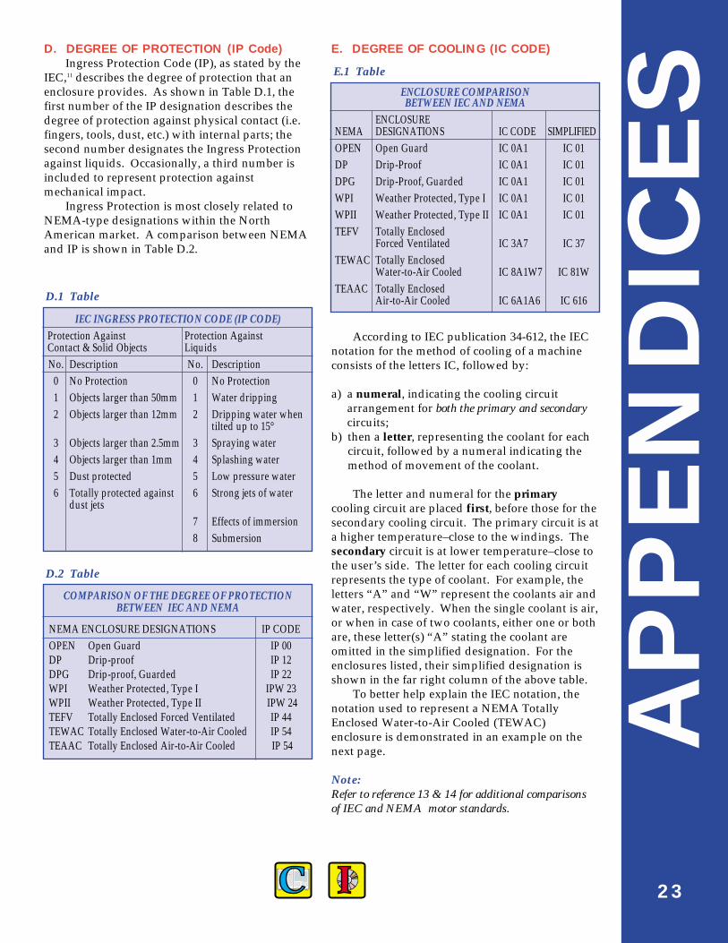
D. DEGREE OF PROTECTION (IP Code)Ingress Protection Code (IP), as stated by the
IEC,11 describes the degree of protection that anenclosure provides. As shown in Table D.1, thefirst number of the IP designation describes thedegree of protection against physical contact (i.e.fingers, tools, dust, etc.) with internal parts; thesecond number designates the Ingress Protectionagainst liquids. Occasionally, a third number isincluded to represent protection againstmechanical impact.
Ingress Protection is most closely related toNEMA-type designations within the NorthAmerican market. A comparison between NEMAand IP is shown in Table D.2.
IEC INGRESS PROTECTION CODE (IP CODE)Protection Against Protection AgainstContact & Solid Objects LiquidsNo. Description No. Description
0 No Protection 0 No Protection1 Objects larger than 50mm 1 Water dripping2 Objects larger than 12mm 2 Dripping water when
tilted up to 15°3 Objects larger than 2.5mm 3 Spraying water4 Objects larger than 1mm 4 Splashing water5 Dust protected 5 Low pressure water6 Totally protected against 6 Strong jets of water
dust jets7 Effects of immersion8 Submersion
COMPARISON OF THE DEGREE OF PROTECTIONBETWEEN IEC AND NEMA
NEMA ENCLOSURE DESIGNATIONS IP CODEOPEN Open Guard IP 00DP Drip-proof IP 12DPG Drip-proof, Guarded IP 22WPI Weather Protected, Type I IPW 23WPII Weather Protected, Type II IPW 24TEFV Totally Enclosed Forced Ventilated IP 44TEWAC Totally Enclosed Water-to-Air Cooled IP 54TEAAC Totally Enclosed Air-to-Air Cooled IP 54
E. DEGREE OF COOLING (IC CODE)
ENCLOSURE COMPARISONBETWEEN IEC AND NEMA
ENCLOSURE NEMA DESIGNATIONS IC CODE SIMPLIFIEDOPEN Open Guard IC 0A1 IC 01DP Drip-Proof IC 0A1 IC 01DPG Drip-Proof, Guarded IC 0A1 IC 01WPI Weather Protected, Type I IC 0A1 IC 01WPII Weather Protected, Type II IC 0A1 IC 01TEFV Totally Enclosed
Forced Ventilated IC 3A7 IC 37TEWAC Totally Enclosed
Water-to-Air Cooled IC 8A1W7 IC 81WTEAAC Totally Enclosed
Air-to-Air Cooled IC 6A1A6 IC 616
According to IEC publication 34-612, the IECnotation for the method of cooling of a machineconsists of the letters IC, followed by:
a) a numeral, indicating the cooling circuitarrangement for both the primary and secondarycircuits;
b) then a letter, representing the coolant for eachcircuit, followed by a numeral indicating themethod of movement of the coolant.
The letter and numeral for the primarycooling circuit are placed first, before those for thesecondary cooling circuit. The primary circuit is ata higher temperature–close to the windings. Thesecondary circuit is at lower temperature–close tothe user’s side. The letter for each cooling circuitrepresents the type of coolant. For example, theletters “A” and “W” represent the coolants air andwater, respectively. When the single coolant is air,or when in case of two coolants, either one or bothare, these letter(s) “A” stating the coolant areomitted in the simplified designation. For theenclosures listed, their simplified designation isshown in the far right column of the above table.
To better help explain the IEC notation, thenotation used to represent a NEMA TotallyEnclosed Water-to-Air Cooled (TEWAC)enclosure is demonstrated in an example on thenext page.
Note: Refer to reference 13 & 14 for additional comparisons of IEC and NEMA motor standards.
D.1 Table
E.1 Table
D.2 Table

APPEN
DIC
ES
24
An Example to Demonstrate the IC Code
Complete notation . . . . . . . . . . . . . . . . . . . . . . . . . . . . . . . . . . . I C 8 A 1 W 7Simplified notation . . . . . . . . . . . . . . . . . . . . . . . . . . . . . . . . . . . I C 8 1 W
1. Code Letters (International Cooling)2. Circuit Arrangement3. Primary Circuit
3.1 Primary Coolant3.2 Method of Movement of Primary Coolant
4. Secondary Circuit (if applicable)4.1 Secondary Coolant4.2 Method of Movement of Secondary Coolant
Circuit Arrangement
Numeral Brief description
0 Free circulation
1 Inlet pipe or inlet duct circulated
2 Outlet pipe or outlet duct circulated
3 Inlet & outlet pipe or duct circulated
4 Frame surface cooled
5 Integral heat exchanger (using surrounding medium)
6 Machine-mounted heat exchanger (using surrounding medium)
7 Integral heat exchanger medium
8 Machine-mounted heat exchanger (using remote medium)
9 Separate heat exchanger (using surrounding or remote medium)
Method of Movement
Numeral Brief description
0 Free convection
1 Self-circulation
2 Reserved for future use
3 Reserved for future use
4 Reserved for future use
5 Integral independent component
6 Machine-mounted independent component
7 Separate and independent component or coolant system pressure
8 Relative displacement
9 All other components

APPEN
DIC
ES
25
F. Comparison of Standards between Major Countries
COUNTRY STANDARD NUMBER or SOURCE OF STANDARD
Countries Worldwide IEC 79-1 (Flameproof ‘d’ type)IEC 79-2 (Pressurized ‘p’ type)IEC 79-7 (Increased Safety ‘e’ type)IEC 79-15 (Non-Sparking ‘n’ type)
European Countries* CENELEC—EN Standards:EN50 014 (General Requirements) EN50 016 (Pressurized)EN50 018 (Flameproof)EN50 019 (Increased Safety)
UK British Standard Institution:BS5501-1�≡ EN50 014BS5501-3�≡ EN50 016BS5501-5�≡ EN50 018BS5501-6�≡ EN50 019
USA UL698 (1973)UL844 (1978)NEC/NFPA 70 (1993)NFPA 496 (1993)
Germany VDE 0171 ≡ EN Standards:EN50 014 EN50 019
Australia Standards Association of Australia (SAA):AS 2380-4 (1994) ≡ EN50 016
Japan “Recommended Practice for Explosion-Protected Electrical Installationsin General Industries”
* CENELEC members include: Austria, Belgium, Denmark, Finland, France, Ireland, Italy, Luxembourg,Netherlands, Norway, Portugal, Spain, Sweden, and Switzerland.
APPEN
DIC
ES
26
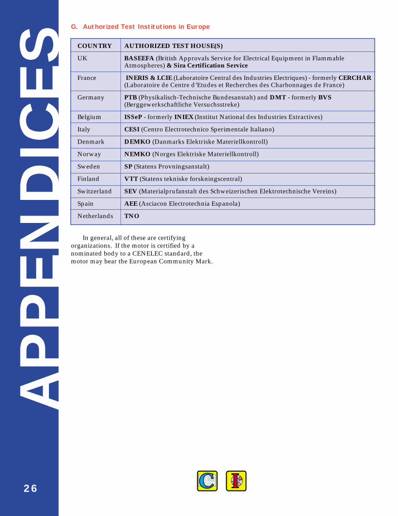
COUNTRY AUTHORIZED TEST HOUSE(S)
UK BASEEFA (British Approvals Service for Electrical Equipment in FlammableAtmospheres) & Sira Certification Service
France INERIS & LCIE (Laboratoire Central des Industries Electriques) - formerly CERCHAR(Laboratoire de Centre d’Etudes et Recherches des Charbonnages de France)
Germany PTB (Physikalisch-Technische Bundesanstalt) and DMT - formerly BVS(Berggewerkschaftliche Versuchsstreke)
Belgium ISSeP - formerly INIEX (Institut National des Industries Extractives)
Italy CESI (Centro Electrotechnico Sperimentale Italiano)
Denmark DEMKO (Danmarks Elektriske Materiellkontroll)
Norway NEMKO (Norges Elektriske Materiellkontroll)
Sweden SP (Statens Provningsanstalt)
Finland VTT (Statens tekniske forskningscentral)
Switzerland SEV (Materialprufanstalt des Schweizerischen Elektrotechnische Vereins)
Spain AEE (Asciacon Electrotechnia Espanola)
Netherlands TNO
G. Authorized Test Institutions in Europe
In general, all of these are certifyingorganizations. If the motor is certified by anominated body to a CENELEC standard, themotor may bear the European Community Mark.
27
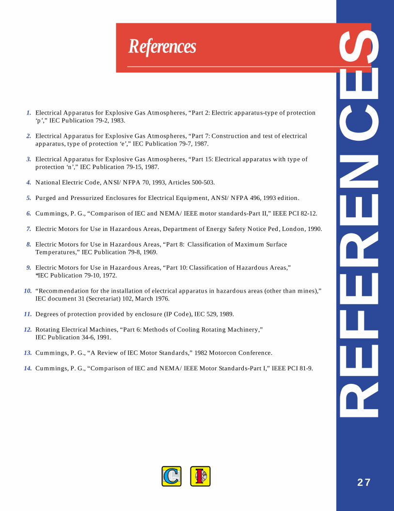
References
1. Electrical Apparatus for Explosive Gas Atmospheres, “Part 2: Electric apparatus-type of protection‘p’,” IEC Publication 79-2, 1983.
2. Electrical Apparatus for Explosive Gas Atmospheres, “Part 7: Construction and test of electricalapparatus, type of protection ‘e’,” IEC Publication 79-7, 1987.
3. Electrical Apparatus for Explosive Gas Atmospheres, “Part 15: Electrical apparatus with type ofprotection ‘n’,” IEC Publication 79-15, 1987.
4. National Electric Code, ANSI/NFPA 70, 1993, Articles 500-503.
5. Purged and Pressurized Enclosures for Electrical Equipment, ANSI/NFPA 496, 1993 edition.
6. Cummings, P. G., “Comparison of IEC and NEMA/IEEE motor standards-Part II,” IEEE PCI 82-12.
7. Electric Motors for Use in Hazardous Areas, Department of Energy Safety Notice Ped, London, 1990.
8. Electric Motors for Use in Hazardous Areas, “Part 8: Classification of Maximum SurfaceTemperatures,” IEC Publication 79-8, 1969.
9. Electric Motors for Use in Hazardous Areas, “Part 10: Classification of Hazardous Areas,” *IEC Publication 79-10, 1972.
10. “Recommendation for the installation of electrical apparatus in hazardous areas (other than mines),”IEC document 31 (Secretariat) 102, March 1976.
11. Degrees of protection provided by enclosure (IP Code), IEC 529, 1989.
12. Rotating Electrical Machines, “Part 6: Methods of Cooling Rotating Machinery,” IEC Publication 34-6, 1991.
13. Cummings, P. G., “A Review of IEC Motor Standards,” 1982 Motorcon Conference.
14. Cummings, P. G., “Comparison of IEC and NEMA/IEEE Motor Standards-Part I,” IEEE PCI 81-9.R
EFE
REN
CES
200-SYN-97
Greg RomeGreg Rome is a design electrical engineer for Dresser Rand/Electric
Machinery Division. Greg graduated with Bachelor of Science Degree inElectrical Engineering from the Institute of Technology, University ofMinnesota. Greg‘s design specialty is motor enclosures.
Jim CaseyJim Casey is a Senior Design Electrical Engineer for Dresser-Rand/Electric
Machinery Division. Jim specializes in slow speed synchronous and inductionmotor design. Jim obtained his B.S. degree in Electrical Engineering at theUniversity of Minnesota in December of 1985.
About the authorsAU
THORS
Electric Machinery Company800 Central Avenue; Minneapolis, MN 55413Business: (612) 978-8000 Fax: (612) 378-8054w w w. e l e c t r i c m a c h i n e r y. c o m