synchronous digital hierarchy (sdh); sdh leased lines ... · pdf filefinal draft en 301 164...
TRANSCRIPT
Final draft EN 301 164 V1.1.1 (1999-02)European Standard (Telecommunications series)
Transmission and Multiplexing (TM);Synchronous Digital Hierarchy (SDH);
SDH leased lines;Connection characteristics
ETSI
Final draft EN 301 164 V1.1.1 (1999-02)2
ReferenceDEN/TM-03072 (as000ico.PDF)
Keywordsleased line, ONP, SDH, transmission
ETSI
Postal addressF-06921 Sophia Antipolis Cedex - FRANCE
Office address650 Route des Lucioles - Sophia Antipolis
Valbonne - FRANCETel.: +33 4 92 94 42 00 Fax: +33 4 93 65 47 16
Siret N° 348 623 562 00017 - NAF 742 CAssociation à but non lucratif enregistrée à laSous-Préfecture de Grasse (06) N° 7803/88
Individual copies of this ETSI deliverablecan be downloaded from
http://www.etsi.orgIf you find errors in the present document, send your
comment to: [email protected]
Copyright Notification
No part may be reproduced except as authorized by written permission.The copyright and the foregoing restriction extend to reproduction in all media.
© European Telecommunications Standards Institute 1999.All rights reserved.

ETSI
Final draft EN 301 164 V1.1.1 (1999-02)3
Contents
Intellectual Property Rights................................................................................................................................5
Foreword ............................................................................................................................................................5
1 Scope........................................................................................................................................................6
2 References................................................................................................................................................6
3 Definitions, symbols and abbreviations...................................................................................................73.1 Definitions ......................................................................................................................................................... 73.2 Symbols ............................................................................................................................................................. 83.3 Abbreviations..................................................................................................................................................... 8
4 Characteristics of VC-4, VC-3, VC-2 and VC-12 leased line connections ...........................................104.1 Tolerance of Virtual Container (VC) timing.................................................................................................... 104.2 Transfer delay .................................................................................................................................................. 104.3 Jitter ................................................................................................................................................................. 104.4 Error performance............................................................................................................................................ 10
5 Characteristics of VC-4 leased line connections ...................................................................................115.1 Information transfer susceptance ..................................................................................................................... 115.2 Error performance............................................................................................................................................ 115.2.1 Bringing into service limits ........................................................................................................................ 115.2.2 Performance objectives .............................................................................................................................. 115.2.3 Availability................................................................................................................................................. 12
6 Characteristics of VC-3 leased line connections ...................................................................................126.1 Information transfer susceptance ..................................................................................................................... 126.2 Error performance............................................................................................................................................ 126.2.1 Bringing into service limits ........................................................................................................................ 126.2.2 Performance objectives .............................................................................................................................. 136.2.3 Availability................................................................................................................................................. 13
7 Characteristics of VC-2 leased line connections ...................................................................................137.1 Information transfer susceptance ..................................................................................................................... 137.2 Error performance............................................................................................................................................ 147.2.1 Bringing into service limits ........................................................................................................................ 147.2.2 Performance objectives .............................................................................................................................. 147.2.3 Availability................................................................................................................................................. 14
8 Characteristics of VC-12 leased line connections .................................................................................158.1 Information transfer susceptance ..................................................................................................................... 158.2 Error performance............................................................................................................................................ 158.2.1 Bringing into service limits ........................................................................................................................ 158.2.2 Performance objectives .............................................................................................................................. 168.2.3 Availability................................................................................................................................................. 16
Annex A (normative): Test methods ..................................................................................................17
A.1 General ...................................................................................................................................................17A.1.1 Equipment connection ..................................................................................................................................... 17
A.2 Test methods ..........................................................................................................................................17A.2.1 Leased line timing tolerance, susceptance and symmetry ................................................................................ 17A.2.2 Delay................................................................................................................................................................ 18A.2.3 Alarm Indication Signal (AIS) generation ....................................................................................................... 19A.2.4 Error performance............................................................................................................................................ 20

ETSI
Final draft EN 301 164 V1.1.1 (1999-02)4
Annex B (informative): Derivation of error performance limits.......................................................21
B.1 Introduction............................................................................................................................................21
B.2 Reference connections ...........................................................................................................................21B.2.1 Terrestrial connection ...................................................................................................................................... 21B.2.2 Satellite connection.......................................................................................................................................... 22
B.3 Error performance objectives.................................................................................................................22
B.4 Long term error performance.................................................................................................................23
B.5 Error performance figures......................................................................................................................23
Annex C (informative): Defects and consequent actions at leased line connections........................25
C.1 Explanation of defect detection and consequent actions of atomic function.........................................25
C.2 Handling of defects along a leased line connection or at the leased line interface ...............................25
Annex D (informative): Configuration of a lower order VC leased line connection .......................28
Annex E (informative): Bibliography...................................................................................................30
History..............................................................................................................................................................31

ETSI
Final draft EN 301 164 V1.1.1 (1999-02)5
Intellectual Property RightsIPRs essential or potentially essential to the present document may have been declared to ETSI. The informationpertaining to these essential IPRs, if any, is publicly available for ETSI members and non-members, and can be foundin SR 000 314: "Intellectual Property Rights (IPRs); Essential, or potentially Essential, IPRs notified to ETSI in respectof ETSI standards", which is available free of charge from the ETSI Secretariat. Latest updates are available on theETSI Web server (http://www.etsi.org/ipr).
Pursuant to the ETSI IPR Policy, no investigation, including IPR searches, has been carried out by ETSI. No guaranteecan be given as to the existence of other IPRs not referenced in SR 000 314 (or the updates on the ETSI Web server)which are, or may be, or may become, essential to the present document.
ForewordThis European Standard (Telecommunications series) has been produced by ETSI Technical Committee Transmissionand Multiplexing (TM), and is now submitted for the Voting phase of the ETSI standards Two-step ApprovalProcedure.
Proposed national transposition dates
Date of latest announcement of this EN (doa): 3 months after ETSI publication
Date of latest publication of new National Standardor endorsement of this EN (dop/e): 6 months after doa
Date of withdrawal of any conflicting National Standard (dow): 6 months after doa

ETSI
Final draft EN 301 164 V1.1.1 (1999-02)6
1 ScopeThe present document specifies the technical requirements and test principles for bi-directional and symmetrical leasedline connections of SDH virtual containers, i.e. VC-4, VC-3, VC-2 and VC-12. Signals transmitted across the leased lineconnections are subject to restrictions (e.g. to the payload independent path overhead) and impairments (e.g. transferdelay, jitter, wander, errors, etc.).
A connection is presented via interfaces at Network Termination Points (NTPs) and includes any equipment that mayprovide the NTP. Together with the companion standard, EN 301 165 [4] defining the network and terminal interfacepresentation, the present document describes the technical characteristics of the leased line service offered to the user.
The present document is applicable for leased lines, including part time leased lines, for which the establishment orrelease does not require any protocol exchange or other intervention at the NTP.
The present document specifies compliance tests for the connection requirements. The present document does notinclude details concerning the implementation of tests, nor does it include information of any relevant regulations.
2 ReferencesThe following documents contain provisions which, through reference in this text, constitute provisions of the presentdocument.
• References are either specific (identified by date of publication, edition number, version number, etc.) ornon-specific.
• For a specific reference, subsequent revisions do not apply.
• For a non-specific reference, the latest version applies.
• A non-specific reference to an ETS shall also be taken to refer to later versions published as an EN with the samenumber.
[1] EN 300 417-2-1: "Transmission and Multiplexing (TM); Generic requirements of transportfunctionality of equipment; Part 2-1: Synchronous Digital Hierarchy (SDH) and PlesiochronousDigital Hierarchy (PDH) physical section layer functions".
[2] EN 300 417-3-1: "Transmission and Multiplexing (TM); Generic requirements of transportfunctionality of equipment; Part 3-1: Synchronous Transport Module-N (STM-N) regenerator andmultiplex section layer functions".
[3] EN 300 417-4-1: "Transmission and Multiplexing (TM); Generic requirements of transportfunctionality of equipment; Part 4-1: Synchronous Digital Hierarchy (SDH) path layer functions".
[4] EN 301 165: "Transmission and Multiplexing (TM); Synchronous Digital Hierarchy (SDH): SDHleased lines; Network and terminal interface presentation".
[5] ITU-T Recommendation G.826 (1996): "Error performance parameters and objectives forinternational, constant bit rate digital paths at or above the primary rate".
[6] EN 300 417-1-1: "Transmission and Multiplexing (TM); Generic requirements of transportfunctionality of equipment; Part 1-1: Generic processes and performance".
[7] EN 300 462-2: "Transmission and Multiplexing (TM); Generic requirements for synchronizationnetworks; Part 2: Synchronization network architecture".

ETSI
Final draft EN 301 164 V1.1.1 (1999-02)7
3 Definitions, symbols and abbreviations
3.1 DefinitionsFor the purposes of the present document, the following terms and definitions apply:
layer: a concept used to allow the transport network functionality to be described hierarchically as successive levels;each layer being solely concerned with the generation and transfer of its "characteristic information"
client/server layer: any two adjacent network layers are associated in a client/server relationship. Each transportnetwork layer provides transport to the layer above and uses transport from the layers below. The layer providingtransport is termed a "server", the layer using transport is termed "client"
Remote Defect Indication (RDI): a signal which conveys the defect status of the characteristic information received bythe Trail Termination sink function back to the network element which contains the characteristic informationoriginating trail termination source function
Remote Error Indication (REI): a signal which conveys either the exact or truncated number of error detection codeviolations within the characteristic information (as detected by the trail termination sink function) back to the networkelement which contains the characteristic information originating trail termination source function
AU-4-AIS: an STM-N signal in which the entire capacity of an Administrative Unit 4 (AU-4) is set to logic "1"
TU-m-AIS: an STM-N signal in which the entire capacity of a TU-m is set to logic "1"
Characteristic Information (CI): a signal of specific rate and format which is transferred within and between"sub-networks", and presented to an "adaptation" function for "transport" by the server layer network
Connection Point (CP): a "reference point" where the output of a "trail termination source" or a "connection" is boundto the input of another "connection", or where the output of a "connection" is bound to the input of a "trail terminationsink" . The "connection point" is characterized by the information which passes across it. A bi-directional "connectionpoint" is formed by the association of a contra-directional pair
Termination Connection Point (TCP): a special case of a "connection point" where a "trail termination" function isbound to an "adaptation" function or a "connection" function
defect: the density of anomalies has reached a level where the ability to perform a required function has beeninterrupted. Defects are used as input for PERFORMANCE MANAGEMENT, the control of consequent actions, andthe determination of fault cause

ETSI
Final draft EN 301 164 V1.1.1 (1999-02)8
3.2 SymbolsThe diagrammatic conventions and nomenclature used in the present document for adaptation, termination andconnection functions (used to describe the atomic functions) are taken from EN 300 417-1-1 [6] and are shown infigure 1.
Sink
S ink
Sou rce
Source b id irectiona l
bid irectio na l
bid irectionalunidirectiona l
Adapta tion functions from Server layer Y to C lien t laye r Z
Y /Z Y/Z Y/Z
Y Y Y
Trail Term ination functions in layer Y
C onnection functions in layer Y
YY
Y/Z
Y
Y/Z
Y
Y/Z
Ybid irectio na lSou rceSink
Tra il Term ina tion function in layer Y and Adapta tion function to layer Z
NOTE: If the above symbols are used for generic figures, i.e. not for specific layers, the layer references Y and Zmay be omitted. Alternatively, the references may be to the type of function or layer, e.g. supervision,protection.
Figure 1: Symbols and diagrammatic conventions
3.3 AbbreviationsFor the purposes of the present document, the following abbreviations apply:
A Adaptation functionAI Adapted Information

ETSI
Final draft EN 301 164 V1.1.1 (1999-02)9
AIS Alarm Indication SignalAU Administrative UnitAU-n Administrative Unit, level nBBE Background Block ErrorBBER Background Block Error RatioBIP Bit Interleaved ParityBIP-N Bit Interleaved Parity, width NC Connection functionCI Characteristic InformationCP Connection PointEMC Electromagnetic CompatibilityES Errored SecondES1 STM-1 Electrical SectionLOF Loss Of FrameLOM Loss Of MultiframeLOP Loss Of PointerLOS Loss Of SignalMS Multiplex SectionMS1 STM-1 Multiplex SectionMS4 STM-4 Multiplex SectionNE Network ElementNNI Network Node InterfaceNT Network TerminationNTP Network Termination PointOS Optical SectionOS1 STM-1 Optical SectionOS4 STM-4 Optical SectionPDH Plesiochronous Digital HierarchyPLM PayLoad MismatchRDI Remote Defect IndicationREI Remote Error IndicationRI Remote InformationRX ReceiveS12 VC-12 path layerS2 VC-2 path layerS3 VC-3 path layerS4 VC-4 path layerSDH Synchronous Digital HierarchySES Severely Errored SecondSF Signal FailSk SinkSo SourceSSF Server Signal FailSTM Synchronous Transport ModuleSTM-N Synchronous Transport Module, level NTCP Terminal Connection PointTE Terminal EquipmentTIM Trace Identifier MismatchTSF Trail Signal FailTSS Test Signal StructureTSSx Test Signal Structure 1, 3 or 4TT Trail Termination functionTTP Trail Termination PointTU Tributary UnitTU-m Tributary Unit, level mTX TransmitUNEQ UnequippedUTC Universal Time Co-ordinatedVC Virtual ContainerVC-n Virtual Container, level n

ETSI
Final draft EN 301 164 V1.1.1 (1999-02)10
4 Characteristics of VC-4, VC-3, VC-2 and VC-12leased line connections
4.1 Tolerance of Virtual Container (VC) timingRequirement: The leased line connection shall carry user timing with a tolerance of ±4,6 ppm
NOTE: For optimum jitter and wander performance of Plesiochronous Digital Hierarchy (PDH) signal carriedover a end to end Virtual Container (VC), it is recommended to generate VC timing at the nominalfrequency. The recommended method of Synchronous Digital Hierarchy (SDH) synchronization isspecified in EN 300 462-2 [7]. It should be noted that a systematic offset of the VC timing from thenominal VC frequency will result in periodic pointer adjustments at the output of the VC leased lineconnection. The SDH section signal which is transmitted from the Network Termination (NT) is carrying,under normal condition, the timing of the leased line network and may be used to generate the VC timingat the terminal interface.
4.2 Transfer delayRequirement: The requirement depends upon whether satellite connection is involved in the connection or not:
− for connection where satellite transmission is not involved, the one way end-to-end delay shall be less than(10 + 0,01 G) ms, where G is the geographical distance in kilometres; or
− for connection where satellite transmission is involved, the one way end-to-end delay shall be less than 350 ms.
4.3 JitterThe leased line connection shall operate as specified when the jitter at the leased line input is within the limits given inthe companion standard EN 301 165 [4].
NOTE 1: The jitter and wander requirements of the Synchronous Transport Module, level N (STM-N) sectionlayers are given at the associated Physical Section Layer to Regenerator Section Layer adaptationfunctions as specified in EN 300 417-2-1 [1].
NOTE 2: Jitter requirements of the VC-4 path are specified by the requirements for AU-4 pointer justificationevents of the Multiplex Section Layer to VC-4 path Layer adaptation function which is specified inEN 300 417-3-1 [2].
NOTE 3: Jitter requirements of the lower order VC paths are specified by the requirements for TU-3/2/12 pointerjustification events of the "VC-4 Layer to VC-3, VC-2 and VC-12 Layer Adaptation functions, S4/Sx_A"which are specified EN 300 417-4-1 [3].
NOTE 4: Wander at the section layer may create pointer justification at VC path layers. Existing ETSs for leasedline connection characteristics consider wander is irrelevant for a single leased line connection. Thatapproach might be unacceptable for SDH leased lines.
4.4 Error performanceITU-T Recommendation G.826 [5] is used as a basis for deriving the error performance objectives specified in thepresent document. The performance parameters referred to in the present document are as those defined in ITU-TRecommendation G.826 [5]. The performance objective tables in the present document apply for a 24 hour test period.They are derived using ITU-T Recommendation G.826 [5] as a basis. Detailed derivation of the performance objectivesis described in annex B of the present document.

ETSI
Final draft EN 301 164 V1.1.1 (1999-02)11
5 Characteristics of VC-4 leased line connections
5.1 Information transfer susceptanceRequirement: The connection shall be capable of transferring transparently a complete and bi-directional VC-4 exceptthe N1 byte when the VC-4 is generated according to EN 301 165 [4], subclause 4.3.1. The structure of a VC-4 is shownin figure 2. The bytes of a VC-4 are transmitted with a frequency of 8 kHz, i.e. the frame length is 125 µs.
When a defect occurs:
− along the leased line connection; or
− at the leased line input (refer to EN 301 165 [4]);
AU4-AIS shall occur at the far end output.
VC-4 payload(9 x 260 bytes)
1
2
9
J1
C2
B3
F2
H4
G1
F3
K3
N1
1 2 261
NOTE: The contents of B3 may change at the tandem connection monitoring processes. The integrity of parityinformation of B3 is maintained through the leased line.
Figure 2: Structure of a VC-4
5.2 Error performance
5.2.1 Bringing into service limits
There are no requirements under the present document.
5.2.2 Performance objectives
Requirement: The performance of a VC-4 leased line either in service or taken out of service in order to perform anerror measurement shall meet the requirements of table 1.
Table 1: Performance objectives over a 24 hour test period for a block length of 18 792 bits (VC-4)
Performance Terrestrial Satelliteparameter Ratio (mean) S1 (note) Ratio (mean) S1 (note)
ES 0,08 ≤ 6 746 s 0,12 ≤ 10 575 sSES 0,001 ≤ 68 s 1,56 × 10⁻³ ≤ 112 sBBE 1,0 × 10⁻⁴ ≤ 68 594 blocks 1,56 × 10⁻⁴ ≤ 107 170 blocks
NOTE: The threshold S1 is defined in clause B.4.

ETSI
Final draft EN 301 164 V1.1.1 (1999-02)12
5.2.3 Availability
There are no requirements under the present document.
6 Characteristics of VC-3 leased line connections
6.1 Information transfer susceptanceRequirement: The connection shall be capable of transferring transparently a complete and bi-directional VC-3 exceptthe N1 byte. The structure of a VC-3 is shown in figure 3. The bytes of a VC-3 are transmitted with a frequency of8 kHz, i.e. the frame length is 125 µs.
When a defect occurs:
− along the leased line connection; or
− at the leased line input (refer to EN 301 165 [4]);
TU3-AIS shall occur at the far end output.
VC-3 payload(9 x 84 bytes)
1
2
9
J1
C2
B3
F2
H4
G1
F3
K3
N1
1 2 85
NOTE: The contents of B3 may change at the tandem connection monitoring processes. The integrity of parityinformation of B3 is maintained through the leased line.
Figure 3: Structure of a VC-3
6.2 Error performance
6.2.1 Bringing into service limits
There are no requirements under the present document.
ETSI
Final draft EN 301 164 V1.1.1 (1999-02)13
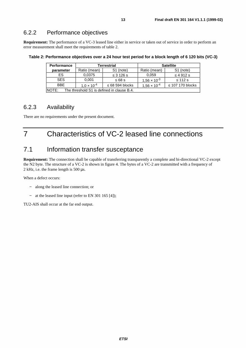
6.2.2 Performance objectives
Requirement: The performance of a VC-3 leased line either in service or taken out of service in order to perform anerror measurement shall meet the requirements of table 2.
Table 2: Performance objectives over a 24 hour test period for a block length of 6 120 bits (VC-3)
Performance Terrestrial Satelliteparameter Ratio (mean) S1 (note) Ratio (mean) S1 (note)
ES 0,0375 ≤ 3 126 s 0,059 ≤ 4 912 sSES 0,001 ≤ 68 s 1,56 × 10⁻³ ≤ 112 sBBE 1,0 × 10⁻⁴ ≤ 68 594 blocks 1,56 × 10⁻⁴ ≤ 107 170 blocks
NOTE: The threshold S1 is defined in clause B.4.
6.2.3 Availability
There are no requirements under the present document.
7 Characteristics of VC-2 leased line connections
7.1 Information transfer susceptanceRequirement: The connection shall be capable of transferring transparently a complete and bi-directional VC-2 exceptthe N2 byte. The structure of a VC-2 is shown in figure 4. The bytes of a VC-2 are transmitted with a frequency of2 kHz, i.e. the frame length is 500 µs.
When a defect occurs:
− along the leased line connection; or
− at the leased line input (refer to EN 301 165 [4]);
TU2-AIS shall occur at the far end output.

ETSI
Final draft EN 301 164 V1.1.1 (1999-02)14
1
2
107
108
109
215
214
216
321
322
323
428
V5
J2
K4
N2
VC-2 payload(106 bytes)
VC-2 payload(106 bytes)
VC-2 payload(106 bytes)
VC-2 payload(106 bytes)
NOTE: The contents of V5[1,2] may change at the tandem connection monitoring processes. The parityinformation of the BIP-2 is maintained through the leased line.
Figure 4: Structure of a VC-2
7.2 Error performance
7.2.1 Bringing into service limits
There are no requirements under the present document.
7.2.2 Performance objectives
Requirement: The performance of a VC-2 leased line either in service or taken out of service in order to perform anerror measurement shall meet the requirements of table 3.
Table 3: Performance objectives over a 24 hour test period for a block length of 3 424 bits (VC-2)
Performance Terrestrial Satelliteparameter Ratio (mean) S1 (note) Ratio (mean) S1 (note)
ES 0,025 ≤ 2 067 s 0,039 ≤ 3 254 sSES 0,001 ≤ 68 s 1,56 × 10⁻³ ≤ 112 sBBE 1,0 × 10⁻⁴ ≤ 17 017 blocks 1,56 × 10⁻⁴ ≤ 26 628 blocks
NOTE: The threshold S1 is defined in clause B.4.
7.2.3 Availability
There are no requirements under the present document.

ETSI
Final draft EN 301 164 V1.1.1 (1999-02)15
8 Characteristics of VC-12 leased line connections
8.1 Information transfer susceptanceRequirement: The connection shall be capable of transferring transparently a complete and bi-directional VC-12 exceptthe N2 byte. The structure of a VC-12 is shown in figure 5. The bytes of a VC-12 are transmitted with a frequency of2 kHz, i.e. the frame length is 500 µs.
When a defect occurs:
− along the leased line connection; or
− at the leased line input (refer to EN 301 165 [4]);
TU12-AIS shall occur at the far end output.
1
2
35
36
37
71
70
72
105
106
107
140
V5
J2
K4
N2
VC-12 payload(34 bytes)
VC-12 payload(34 bytes)
VC-12 payload(34 bytes)
VC-12 payload(34 bytes)
NOTE: The contents of V5[1,2] may change at the tandem connection monitoring processes. The integrity ofparity information BIP-2 is maintained through the leased line.
Figure 5: Structure of a VC-12
8.2 Error performance
8.2.1 Bringing into service limits
There are no requirements under the present document.

ETSI
Final draft EN 301 164 V1.1.1 (1999-02)16
8.2.2 Performance objectives
Requirement: The performance of a VC-12 leased line either in service or taken out of service in order to perform anerror measurement shall meet the requirements of table 4.
Table 4: Performance objectives over a 24 hour test period for a block length of 1 120 bits (VC-12)
Performance Terrestrial Satelliteparameter Ratio (mean) S1 (note 1) Ratio (mean) S1 (note 1)
ES 0,02 ≤ 1 645 s 0,031 ≤ 2 592 sSES 0,001 ≤ 68 s 1,56 × 10⁻³ ≤ 112 s
BBE (note 2) 1,0 × 10⁻⁴ ≤ 17 017 blocks 2,34 × 10⁻⁴ ≤ 26 628 blocksNOTE 1: The threshold S1 is defined in clause B.4.NOTE 2: ITU-T Recommendation G.826 [5], version 1996 changed the BBER from
3 × 10⁻⁴ to 2 × 10⁻⁴.
8.2.3 Availability
There are no requirements under the present document.
ETSI
Final draft EN 301 164 V1.1.1 (1999-02)17
Annex A (normative):Test methods
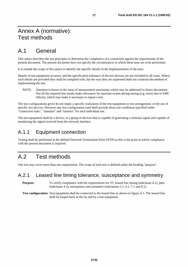
A.1 GeneralThis annex describes the test principles to determine the compliance of a connection against the requirements of thepresent document. The present document does not specify the circumstances in which these tests are to be performed.
It is outside the scope of this annex to identify the specific details of the implementation of the tests.
Details of test equipment accuracy and the specification tolerance of the test devices are not included in all cases. Wheresuch details are provided they shall be complied with, but the way they are expressed shall not constrain the method ofimplementing the test.
NOTE: Attention is drawn to the issue of measurement uncertainty which may be addressed in future documents.Not all the required test results make allowance for spurious events during testing (e.g. errors due to EMCeffects), which may make it necessary to repeat a test.
The test configurations given do not imply a specific realization of the test equipment or test arrangement, or the use ofspecific test devices. However any test configuration used shall provide those test conditions specified under"connection state", "stimulus" and "monitor" for each individual test.
The test equipment shall be a device, or a group of devices that is capable of generating a stimulus signal and capable ofmonitoring the signal received from the network interface.
A.1.1 Equipment connectionTesting shall be performed at the defined Network Termination Point (NTP) as this is the point at which compliancewith the present document is required.
A.2 Test methodsOne test may cover more than one requirement. The scope of each test is defined under the heading "purpose".
A.2.1 Leased line timing tolerance, susceptance and symmetryPurpose: To verify compliance with the requirements for VC leased line timing (subclause 4.1), jitter
(subclause 4.3), susceptance and symmetry (subclauses 5.1, 6.1, 7.1 and 8.1).
Test configuration: Test equipment shall be connected to the leased line as shown in figure A.1. The leased lineshall be looped back at the far end by a test equipment.
ETSI
Final draft EN 301 164 V1.1.1 (1999-02)18
TEST EQUIPMENT
TEST EQUIPMENT
(LOOPBACK) CONNECTION
TX
RX
RX
RX
RX
TX
TX
TX
Stimulus
Monitor
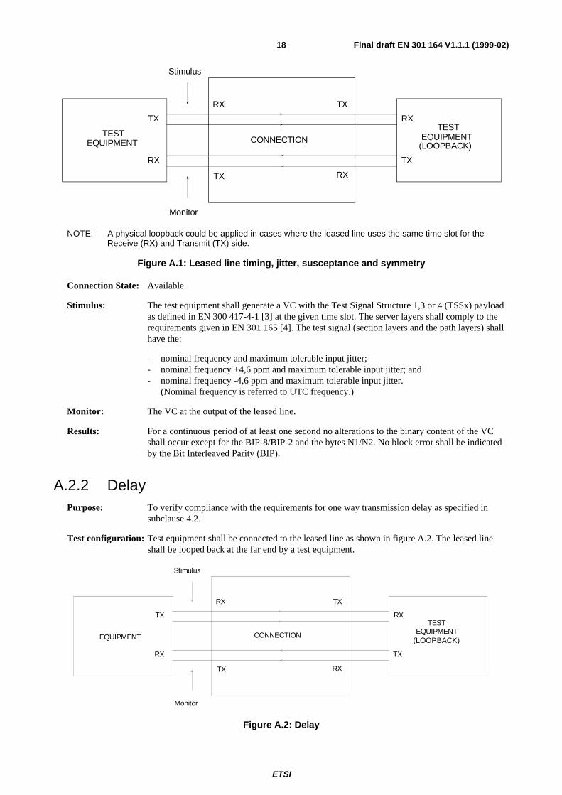
NOTE: A physical loopback could be applied in cases where the leased line uses the same time slot for theReceive (RX) and Transmit (TX) side.
Figure A.1: Leased line timing, jitter, susceptance and symmetry
Connection State: Available.
Stimulus: The test equipment shall generate a VC with the Test Signal Structure 1,3 or 4 (TSSx) payloadas defined in EN 300 417-4-1 [3] at the given time slot. The server layers shall comply to therequirements given in EN 301 165 [4]. The test signal (section layers and the path layers) shallhave the:
- nominal frequency and maximum tolerable input jitter;- nominal frequency +4,6 ppm and maximum tolerable input jitter; and- nominal frequency -4,6 ppm and maximum tolerable input jitter.
(Nominal frequency is referred to UTC frequency.)
Monitor: The VC at the output of the leased line.
Results: For a continuous period of at least one second no alterations to the binary content of the VCshall occur except for the BIP-8/BIP-2 and the bytes N1/N2. No block error shall be indicatedby the Bit Interleaved Parity (BIP).
A.2.2 DelayPurpose: To verify compliance with the requirements for one way transmission delay as specified in
subclause 4.2.
Test configuration: Test equipment shall be connected to the leased line as shown in figure A.2. The leased lineshall be looped back at the far end by a test equipment.
EQUIPMENT
TEST EQUIPMENT CONNECTION
TX
RX
RX
RX
RX
TX
TX
TX
Stimulus
Monitor
(LOOPBACK)
Figure A.2: Delay

ETSI
Final draft EN 301 164 V1.1.1 (1999-02)19
Connection State: Available.
Stimulus: The test equipment shall generate a VC with a distinctive bit pattern whose repetition period isgreater than the round trip delay at the given time slot. The server layers shall comply to therequirements given in EN 301 165 [4].
Monitor: The round trip delay between transmission and reception of the distinctive bit pattern.
Results: The round trip delay after deduction of the delay introduced by the loopback test equipment,shall be less than or equal to twice the delay specified in the requirement of subclause 4.2.
NOTE: This test assumes that the same transmission path is used in both directions. It is not practicable to providea test of the transmission delay in each individual direction.
A.2.3 Alarm Indication Signal (AIS) generationPurpose: To verify compliance with the requirements for AIS generation as specified in subclauses 5.1,
6.1, 7.1 and 8.1.
Test configuration: Test equipment shall be connected to both ends of the leased line (see figure A.3). Eachdirection shall be tested separately.
TEST EQUIPMENT
TEST EQUIPMENT CONNECTION
TX
RX
RX
RX
RX
TX
TX
TX
Stimulus Monitor
NOTE: Alternatively a test configuration according to figure A.1 could be used.
Figure A.3: AIS generation and error
Connection State: Available.
Stimulus: The test equipment shall generate a VC with the TSSx payload as defined inEN 300 417-4-1 [3] at the given time slot. The server layers comply to the requirements givenin EN 301 165 [4]. The test equipment shall generate in sequence the following defects: LossOf Signal (LOS), Loss Of Frame (LOF) AU4-AIS and AU4-Loss Of Pointer (LOP). For lowerorder VC connection the following defects shall be generated in addition: VC-4-TraceIdentifier Mismatch (TIM), VC-4-PayLoad Mismatch (PLM) and Loss Of Multiframe (LOM)(VC-2 and VC-12 only) also in sequence.
Monitor: The Administrative Unit (AU)/Tributary Unit (TU) of the VC.
Results: For VC-4 connection AU4-AIS shall occur on application of a defect. On clearance of thedefect AU4-AIS shall be replaced by the normal signal.
For a lower order VC connection TU-AIS shall occur on application of a defect. On clearanceof the defect TU-AIS shall be replaced by the normal signal.

ETSI
Final draft EN 301 164 V1.1.1 (1999-02)20
A.2.4 Error performancePurpose: To verify compliance with the requirements for error performance as specified in
subclauses 5.2.2, 6.2.2, 7.2.2 and 8.2.2.
Test configuration: Test equipment shall be connected to both ends of the leased line (see figure A.4). Eachdirection shall be tested separately.
TEST EQUIPMENT
TEST EQUIPMENT CONNECTION
TX
RX
RX
RX
RX
TX
TX
TX
Stimulus Monitor
Figure A.4: Error performance measurement
Connection State: Available.
Stimulus: The test equipment shall generate a VC with the TSSx payload as defined inEN 300 417-4-1 [3] at the given time slot. The server layers shall comply to the requirementsgiven in EN 301 165 [4].
The test signal (section and path layers) shall have a timing within the range of nominalfrequency ±4,6 ppm.(Nominal frequency is referred to UTC frequency.)
Monitor: a) the number of errored seconds;b) the number of severely errored seconds;c) the number of background block errors.
Results: When monitoring a line that has been taken out of service to perform a measurement, thenumber or errors, severely errored seconds and background block errors shall be less than theperformance levels given in subclauses 5.2.2, 6.2.2, 7.2.2 and 8.2.2.
NOTE: If the requirements are met during the first continuous period of 24 hours, the test need not be continuedfor the second period of 24 hours.
ETSI
Final draft EN 301 164 V1.1.1 (1999-02)21
Annex B (informative):Derivation of error performance limits
B.1 IntroductionErrors are caused by various influences such as:
- human intervention;
- thermal noise;
- induced voltages in equipment and cables due to lightning, radio transmissions and other electromagnetic effects;
- loss of synchronization following uncontrolled slips;
- joints and connections.
The main cause of errors is induced voltages and such errors frequently occur in dense bursts due to particularphenomena. Due to improvements in technology resulting in part from a greater understanding of electromagneticeffects, there is a long term trend for error rates to reduce.
Studies in ITU-T Recommendations have concluded that error rates for lines have a low dependence on distance.
B.2 Reference connectionsITU-T Recommendation G.826 [5] contains error performance limits for a hypothetical reference connection of27 500 km. In order to apply these figures to a leased line, it is necessary to define reference connections to represent theleased lines covered by the present document. A terrestrial reference connection and a satellite reference connection aredefined in subclauses B.2.1 and B.2.2 based on ITU-T Recommendation G.826 [5].
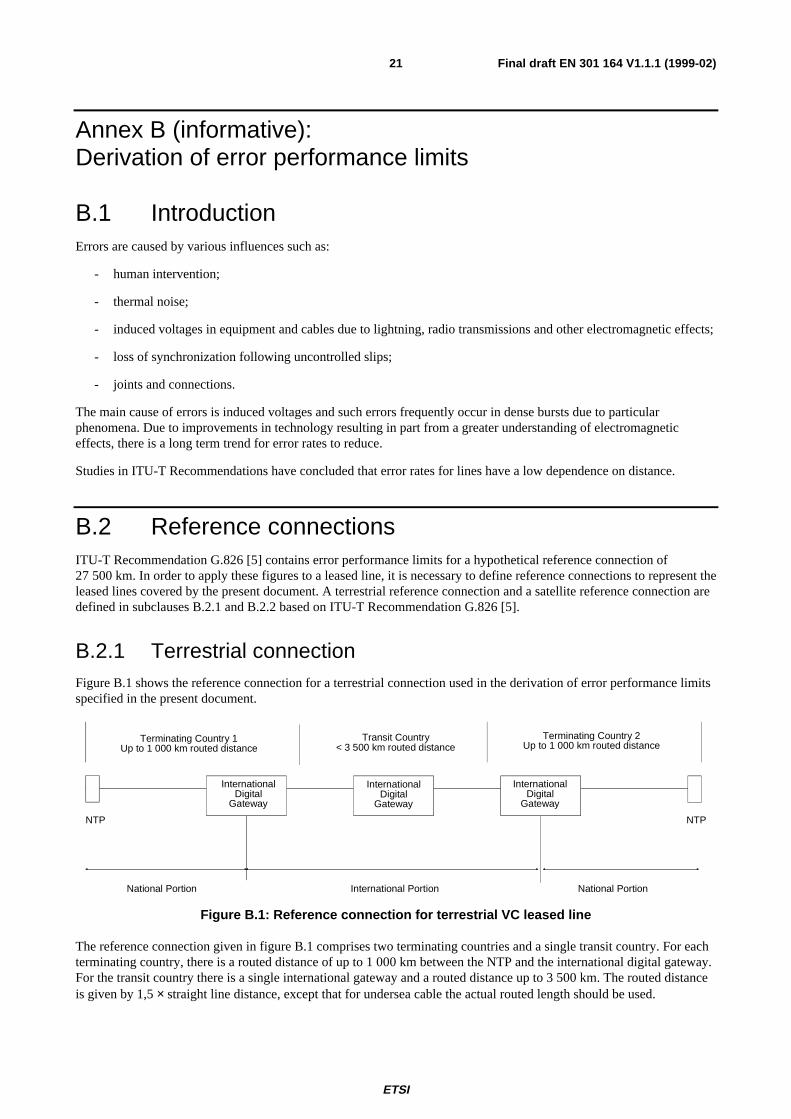
B.2.1 Terrestrial connectionFigure B.1 shows the reference connection for a terrestrial connection used in the derivation of error performance limitsspecified in the present document.
NTP NTP
Transit Country< 3 500 km routed distance
National Portion National PortionInternational Portion
InternationalDigital
Gateway
Terminating Country 2Up to 1 000 km routed distance
InternationalDigital
Gateway
Terminating Country 1Up to 1 000 km routed distance
InternationalDigital
Gateway
Figure B.1: Reference connection for terrestrial VC leased line
The reference connection given in figure B.1 comprises two terminating countries and a single transit country. For eachterminating country, there is a routed distance of up to 1 000 km between the NTP and the international digital gateway.For the transit country there is a single international gateway and a routed distance up to 3 500 km. The routed distanceis given by 1,5 × straight line distance, except that for undersea cable the actual routed length should be used.

ETSI
Final draft EN 301 164 V1.1.1 (1999-02)22
NOTE: This model allows for a total routed distance of up to 5 500 km. Although this reference connection showsseparate national portions, the present document does not apportion errors between different countries andthe errors may be apportioned differently.
B.2.2 Satellite connection
NTP
NTP
Terminating Country 1 Up to 1 000 km routed distance
National Portion National Portion
Terminating Country 2 Up to 1 000 km routed distance
International portion
Satellite Base
Station
Satellite hop
International Digital
Gateway
Satellite Base
Station
International Digital
Gateway
Figure B.2: Reference connection for satellite VC leased line
The reference connection in figure B.2 contains a satellite link connecting the two terminating countries. For eachterminating country a routed distance of 1 000 km is assumed.
B.3 Error performance objectivesTables B.1 and B.2 show the percentage allocation of the overall error performance objectives specified in ITU-TRecommendation G.826 [5] to the various portions of the leased lines specified in the reference connections (terrestrialand satellite) defined in subclause B.2. The tables include both fixed allocations and distance dependent allocations of1 % per 500 km routed distance.
Table B.1: Allocation of error performance objectives derived from ITU-T Recommendation G.826 [5] -terrestrial connection
Path portion (terrestrial link) AllocationTerminating country 1 (fixed allocation) 17,5 %Terminating country 1 (routed 1 000 km) 2,0 %
International transit termination 1,0 %International transit (fixed allocation) 2,0 %International transit (routed 3 500 km) 7,0 %International transit termination 1,0 %
Terminating country 2 (routed 1 000 km) 2,0 %Terminating country 2 (fixed allocation) 17,5 %
TOTAL 50,0 %
Table B.2: Allocation of error performance objectives derived from ITU-T Recommendation G.826 [5] -satellite connection
Path portion (satellite link) AllocationTerminating country 1 (fixed allocation) 17,5 %Terminating country 1 (routed 1 000 km) 2,0 %International termination 2,0 %Satellite connection 35,0 %International termination 2,0 %Terminating country 2 (routed 1 000 km) 2,0 %Terminating country 2 (fixed allocation) 17,5 %
TOTAL 78,0 %

ETSI
Final draft EN 301 164 V1.1.1 (1999-02)23
NOTE: The inclusion of additional transit countries to the terrestrial connection would require an additional fixedallocation (2 %), transit termination (1 %) and a routed portion (1 % per 500 km). Further information isgiven in ITU-T Recommendation G.826 [5].
ITU-T Recommendation G.826 [5] defines error performance objectives in terms of errored seconds, severely erroredseconds and background block errors for a hypothetical reference path of 27 500 km and is taken as the basis of 100 %.
The application of the percentage figures given in tables B.1 and B.2 to the error performance objectives given in ITU-TRecommendation G.826 [5] gives error rates for VC leased lines and shown in row 1 of table 1 to table 4 of the presentdocument.
B.4 Long term error performanceThe error performance ratio derived in subclause B.3 for the specific reference connections can be used to calculate thelong term error performance requirements, expressed as an absolute figure over a 24 hour period; these are given intable 1 to table 4 for the terrestrial and satellite connections.
The error performance requirements specified are, however, statistical figures based on long term measurements (greaterthan one month) which are not statistically valid over a 24 hour measurement period. Therefore ITU-T RecommendationM.2100 presents a method of reducing these limits to 24 hour test limits S1 and S2. S1 is the limit below which there isconfidence that the leased line meets the requirement, S2 is the limit above which there is confidence that the leased linefails to meet the requirement. Between S1 and S2 the results are inconclusive. Therefore, in order to have confidencethat the leased line meets the long term requirement, the 24 hour test result should be better than the limit S1. In theevent that the limit S1 is not met, the test should be repeated a second time.
S1 and S2 are derived from: S requirement requirement1 2= − ×( )
S requirement requirement2 2= + ×( )
B.5 Error performance figuresTable B.3 shows error performance value according to ITU-T Recommendation G.826 [5] compared with the meanvalues of the reference leased line connection and the S1 and S2 values.

ETSI
Final draft EN 301 164 V1.1.1 (1999-02)24
Table B.3: Error performance values according to ITU-T Recommendation G.826 [5] compared withleased line values
VC-455 Mbit/s to 160 Mbit/s Terrestrial Satellite
Parameter G.826 Ratio (mean) Absolute S1 S2 Ratio (mean) Absolute S1 S2ES 16,00% 8,00% 6912 6745,72 7076,26 12,48% 10783 10575 10988SES 0,20% 0,10% 86,4 67,8097 102,869 0,16% 135 112 156BBE 0,02% 0,01% 69120 68594,2 69643,8 0,016% 107827 107170 108482
VC-315 Mbit/s to 55 Mbit/s Terrestrial Satellite
Parameter G.826 Ratio (mean) Absolute S1 S2 Ratio (mean) Absolute S1 S2ES 7,50% 3,75% 3240 3126 3352 5,85% 5054 4912 5195SES 0,20% 0,10% 86 68 103 0,16% 135 112 156BBE 0,020% 0,010% 69120 68594 69644 0,016% 107827 107170 108482
VC-25 Mbit/s to 15 Mbit/s Terrestrial SatelliteParameter G.826 Ratio (mean) Absolute S1 S2 Ratio (mean) Absolute S1 S2
ES 5,00% 2,50% 2160 2067 2251 3,90% 3370 3254 3484SES 0,20% 0,10% 86 68 103 0,16% 135 112 156BBE 0,020% 0,010% 17280 17017 17541 0,016% 26957 26628 27283
VC-121,5 Mbit/s to 5 Mbit/s Terrestrial SatelliteParameter G.826 Ratio (mean) Absolute S1 S2 Ratio (mean) Absolute S1 S2
ES 4,00% 2,00% 1728 1645 1809 3,12% 2696 2592 2798SES 0,20% 0,10% 86 68 103 0,16% 135 112 156BBE 0,020% 0,010% 17280 17017 17541 0,016% 26957 26628 27283

ETSI
Final draft EN 301 164 V1.1.1 (1999-02)25
Annex C (informative):Defects and consequent actions at leased line connections
C.1 Explanation of defect detection and consequentactions of atomic function
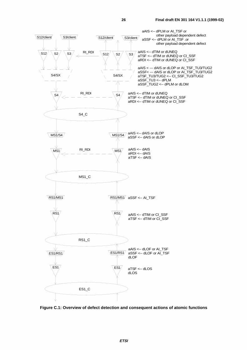
Figure C.1 illustrates the defect detection and consequent actions by means of a functional model. This model showsonly the functions which are relevant lower order VC connections. At the lower order path layer to client layeradaptation function only the non-specific defects are given.
A terminology according to the equipment specification in EN 300 417-x-1 is used:
− Defects begin with a lower case "d" followed by the abbreviation of the defect, e.g. dLOS = Loss of Signaldefect.
− Consequent actions begin with a lower case "a" followed by the abbreviation of the consequent action, e.g.aAIS = action AIS.
− Primitives indicate that a server layer (SSF) or a trail (TSF) is not working. Issuing SSF by an adaptation functionis called aSSF and issuing TSF by a trail termination function is called aTSF. The information is called AI_TSFor CI_SSF respectively.
C.2 Handling of defects along a leased line connection orat the leased line interface
Figure C.2 shows a unidirectional interruption of the physical layer.
NE2: ES1/RS1_TT_SkaAIS ← dLOSaTSF ← dLOS
MS1_TT_Sk aAIS ← dAISaRDI ← dAISaTSF ← dAIS
MS_TT_So inserts RDI pattern "110" in K2[6-8]
S4_TT_Sk aRDI ← CI_SSFaTSF ← CI_SSF
S4_TT_So inserts RDI pattern "1" in G1[5]
TE2: S3_TT_Sk aRDI ← CI_SSFaTSF ← CI_SSF
S4_TT_So inserts RDI pattern "1" in G1[5]
TE1: S3_TT_Sk dRDI
ETSI
Final draft EN 301 164 V1.1.1 (1999-02)26
S4
S4_C
RS1
RS1/MS1
RS1
RS1/MS1
ES1ES1
ES1/RS1 ES1/RS1
ES1_C
RS1_C
MS1
S3/client
MS1
MS1/S4
MS1_C
S4
S4/SX S4/SX
S12 S2 S3S12 S2 S3 RI_RDI
aTSF <-- dLOSdLOS
aAIS <-- dLOF or AI_TSFaSSF <-- dLOF or AI_TSFdLOF
aAIS <-- dTIM or CI_SSFaTSF <-- dTIM or CI_SSF
aSSF <-- AI_TSF
aAIS <-- dAISaRDI <-- dAISaTSF <-- dAIS
aAIS <-- dAIS or dLOPaSSF <-- dAIS or dLOP
aAIS <-- dTIM or dUNEQaTSF <-- dTIM or dUNEQ or CI_SSFaRDI <-- dTIM or dUNEQ or CI_SSF
aAIS < --- dAIS or dLOP or AI_TSF_TU3/TUG2aSSF< --- dAIS or dLOP or AI_TSF_TU3/TUG2aTSF_TU3/TUG2 <-- CI_SSF_TU3/TUG2aSSF_TU3 <-- dPLMaSSF_TUG2 <-- dPLM or dLOM
aAIS <-- dTIM or dUNEQaTSF <-- dTIM or dUNEQ or CI_SSFaRDI <-- dTIM or dUNEQ or CI_SSF
S3/clientS12/client S12/client
aAIS <-- dPLM or AI_TSF or other payload dependent defectaSSF <-- dPLM or AI_TSF .or other payload dependent defect
MS1/S4
RI_RDI
RI_RDI
Figure C.1: Overview of defect detection and consequent actions of atomic functions

ETSI
Final draft EN 301 164 V1.1.1 (1999-02)27
S3
S4
MS1
RS1
ES1
S3
S4
MS1
RS1
ES1
MS1
RS1
ES1
MS1
RS1
ES1
MS1
RS1
ES1
MS1
RS1
ES1
S4
MS1
RS1
ES1
S4
MS1
RS1
ES1
S4
MS1
RS1
ES1
S4
MS1
RS1
ES1
S3
S4
MS1
RS1
ES1
S3
S4
MS1
RS1
ES1 dLOS
aAIS
aAIS
aAIS
aRDI CI_SSF
dRDI
aAIS
aRDI CI_SSF
aRDI CI_SSF
aAIS
dRDI
dRDI
TE1 NE1 NE2 TE2
RDI
RDI
RDI
leased line connection
Figure C.2: Example of an unidirectional LOS defect within a VC-3 leased line

ETSI
Final draft EN 301 164 V1.1.1 (1999-02)28
Annex D (informative):Configuration of a lower order VC leased line connectionFigure D.1 shows an example of lower order VC connections. It shows that path and section could be terminated atdifferent equipment as it is assumed for VC leased line connection. For that reason the requirements for each layer areidentical for the leased line network and the TEs.

ETSI
Final draft EN 301 164 V1.1.1 (1999-02)29
S3
S4
MS1
RS1
ES1
MS1
RS1
ES1
MS1
RS1
OS1
S4
MS1
RS1
OS1
S4
MS16
RS16
OS16
S4
MS16
RS16
OS16
S4
MS4
RS4
OS4
MS4
RS4
OS4
MS1
RS1
OS1
S3
S4
MS1
RS1
OS1
S4
MS1
RS1
ES1
S12
S4
MS1
RS1
ES1
S12
NT NT NE NE TE a TE b TE c
leased line connection
Figure D.1: Example of lower order VC connection generated in one TE and terminated in different TEs

ETSI
Final draft EN 301 164 V1.1.1 (1999-02)30
Annex E (informative):Bibliography
- CCITT Recommendation I.140 (1993): "Attribute techniques for the characterization of telecommunicationservices supported by an ISDN and network capabilities of an ISDN".
- CCITT Recommendation M.1016 (1988): "Assessment of the service availability performance of internationalleased circuits".
- CCITT Supplement number 3.8, Fascicle IV.4 (1988): "Guidelines concerning the measurement of jitter".
- ITU-T Recommendation G.114 (1993): "Mean one-way propagation time".
- ITU-T Recommendation M.2100 (1995): "Performance limits for bringing-into-service and maintenance ofinternational digital paths, sections and transmission systems".
- ITU-T Recommendation M.2101 (1996): "Performance limits for bringing-into-service and maintenance ofinternational SDH paths and multiplex sections".
- ITU-T Recommendation G.704 (1995): "Synchronous frame structures used at 1544, 6312, 2048, 8488 and44 736 kbit/s hierarchical levels".
- I-ETS 300 416: "Transmission and Multiplexing (TM); Availability performance of path elements ofinternational digital paths".

ETSI
Final draft EN 301 164 V1.1.1 (1999-02)31
History
Document history
V1.1.1 March 1998 Public Enquiry PE 9829: 1998-03-20 to 1998-07-17
V1.1.1 February 1999 Vote V 9915: 1999-02-09 to 1999-04-09