synchronous motor design and analysing - universiti malaysia pahang
TRANSCRIPT

SYNCHRONOUS MOTOR DESIGN AND ANALYSING THE OUTPUT
CHARACTERISTICS
MIOR AHMAD FAIZ BIN RIZA
This thesis is submitted as partial fulfillment of the requirements for the award of the
Bachelor of Electrical Engineering (Hons.) (Power System)
Faculty of Electrical & Electronics Engineering
Universiti Malaysia Pahang
NOVEMBER, 2008

ii
ABSTRACT
AC Synchronous Motors range in size from sub-fractional horsepower to over
10,000 horsepower. Smaller synchronous motors can be found in household devices
such as clocks, timers, fans and cassette players, and as stepper motors in computer
disk drives and printers. Larger synchronous motors are used in process industries
and drive equipment such as compressors. Large synchronous motors most
commonly employ a three-phase system. The smaller AC Synchronous Motors
commonly use a single-phase system. Synchronous motor is consists of two parts
those are stator and rotor. Stator is stationary part that produces rotating magnetic
field and then, the rotor locks into step with rotating magnetic field. This paper
focuses on uses the permanent magnet on rotor shaft to produce magnetic field
instead of uses slip rings and carbon brush to supply external dc source to the shaft.
Permanent magnet synchronous motor is also called brushless because the excitation
flux is produced by permanent magnet. Application of neodymium-iron-boron
(Nd2Fe14B) and samarium cobalt (Sm1Co5 and Sm2Co17) rare earth magnets results in
high torque and power density, efficiency, and controllability, reliability, and
ruggedness. The synchronous motor has the same physical stator as induction motor.
Then the output of two type of motor can be analyse and compared the result. The
output that should be considered is frequency, rpm, torque, hp, losses, and efficiency.
From this project we can use the spec of induction motor to guide in design basic
principal of synchronous motor with the same spec. Through of this some of
development should be done to improve the efficiency and reliability of the motor.

1
CHAPTER 1
INTRODUCTION
1.1 Introduction
Synchronous motors are like induction motor in that they both have stator
windings to produce a rotating magnetic field. Unlike an induction motor, the
synchronous motor is excited by an external DC source and therefore requires slip
rings and brushes to provide current to the rotor and produce magnetic field.
An AC Synchronous Motor rotates at a fixed speed, despite of any increase or
decrease in load. The motor will keep its fixes speed until the torque required reaches
its pull out torque (maximum torque). If the load becomes greater then reach motor’s
pull out torque, the AC Synchronous Motor will not slow down because it reaches a
point at which it will stall and stop turning. The pull-out torque is generally 1.5
times the continuously rated torque.
The AC Synchronous motor is an effective way to obtain a fixed speed at a
very low motor system cost. No expensive driver or amplifier is necessary. Most
synchronous motors are used where precise timing and constant speed are required.
AC Synchronous Motors range in size from sub-fractional horsepower to over
10,000 horsepower. Smaller synchronous motors can be found in household devices

2
such as clocks, timers, fans and cassette players, and as stepper motors in computer
disk drives and printers. Larger synchronous motors are used in process industries
and drive equipment such as compressors. Large synchronous motors most
commonly employ a three-phase system. The smaller AC Synchronous Motors
commonly use a single-phase system. The three-phase AC Synchronous Motor is the
focus of this paper. Synchronous motors have the following advantage over non-
synchronous motor.
i. Speed is independent of the load, provided an adequate field current is
applied.
ii. Accurate control in speed and position using open loop controls, eg. stepper
motors.
iii. They will hold their position when a DC current is applied to both the stator
and the rotor windings.
iv. Their power factor can be adjusted to unity by using a proper field current
relative to the load. Also, a "capacitive" power factor, (current phase leads
voltage phase), can be obtained by increasing this current slightly, which can
help achieve a better power factor correction for the whole installation.
v. Their construction allows for increased electrical efficiency when a low speed
is required (as in ball mills and similar apparatus).
1.1.1 Basic construction and operating principle
Three phase AC synchronous motor are commonly used in industrial
applications. This type of motor has three main parts, rotor, stator, and enclosure.
The stator and rotor do the work and the enclosure protects the stator and rotor.
To understand how the synchronous motor works, assume that the application
of three-phase ac power to the stator causes a rotating magnetic field around the
rotor. The rotor is energized with dc (it acts like a bar magnet). The strong rotating
magnetic field attracts the strong rotor field activated by dc. This results in a strong

3
turning force on rotor shaft. Therefore enable rotor to turn a load as it rotates in step
with rotating magnetic field.
1.1.2 Stator The stator is the stationary part of the motor electromagnetic circuit. The
stator is made up of several thin laminations of aluminium or cast iron. Laminations
are used to reduce energy losses that would result if solid core is used. They are
punched and clamped together to form a hollow cylinder.
Stator laminations are stacked together forming hollow cylinder. Coils of
insulated wire are inserted into slots of stator core. When the assembled motor is in
operation the stator winding are connected directly to the power of source. Each
grouping of coils, together with the steel core it surrounds, become and
electromagnet when current is applied. Electromagnetism is the basic principle
behind motor operation.
1.1.3 Rotor
The rotor is the rotating part of the motor electromagnetic circuit. Most of
motor commonly used brush-type rotor that uses slip rings for application of DC field
current to produce magnetic field on rotor. Low voltage DC is used for the rotating
field 120 VDC and 250 VDC are typical. The other type of rotor is rotor permanent
magnet. For this type rotor is completely independent form any external source.

4
1.1.4 Enclosure
The enclosure consists of a frame (or yoke) and two ends bracket (bearing
housings). The stator is mounted inside the frame. The rotor fits inside the stator with
slight air gap separating it from the stator. There is no direct physical connection
between the rotor and the stator. The enclosure protects the internal parts of the
motor from water and other environment elements. The degree of protection depend
the type of enclosure. Bearing mounted on the shaft, support the rotor and allow it to
turn. Fan also mounted on rotor shaft to cool the motor when the shaft is rotating.
1.2 PROBLEM STATEMENT The problem is to produce magnetic field on the rotor side. The magnetic field can
define by use
i. Slip ring and brushes
The use of slip ring and brush need more concern about maintenance
ii. Permanent magnet
Instead of using slip ring and brush the magnetic field on rotor can
replace by use of permanent magnet
Advantage of using permanent magnet
Less maintenance than slip ring and brushes
Completely independent from any external source
Brush voltage drop can be the cause of power loss on machines with
larger field currents

F
b
1 T
1 T
r
For this syn
below shows
1.3 PRO
The objectiv
i. Desig
ii. Anal
iii. Unde
1.4 SCO
This project
rotor part ins
i. The d
ii. Supp
iii. Input
nchronous m
s the synchro
Figu
OJECT OBJ
ve of this pro
gn the basic
lyze the outp
erstand the c
OPE OF PRO
t concentrate
stead of use
desire outpu
ply input vol
t current=0.9
motor is refer
onous motor
ure 1.1: Sync
JECTIVE
oject is to:
principal of
put character
concept of de
OJECT
es of using
slip rings an
ut =approxim
ltage=415V,
90A
rring to use
r block diagr
chronous mo
f synchronou
ristics
esign synchr
permanent m
nd brushes. T
mately ½ hp(
3Ф
e permanent
ram.
otor block di
us motor.
ronous moto
magnet to p
The spec tha
373W)
magnet sha
iagram
or
produce mag
at should be c
aft. Figure 1
gnetic field
considered i
5
.1
in
s

6
CHAPTER 2
THEORY AND LITERATURE REVIEW 2.1 Introduction AC motor is worldwide use in many applications. It is transform from
electrical energy into mechanical energy. There are many types of ac motor, but this
project focusing on the three phase ac synchronous motor. Build without complex
electronic control, synchronous motor is inherently constant speed motors. They
operate absolutely synchronize with line frequency.
In this chapter the researcher will view more about the synchronous motor
including the theory, operation, construction
2.2 Permanent magnet synchronous motor
The PM Synchronous motor is a rotating electric machine where the stator
is a classic three phase stator like that of an induction motor and the rotor has
surface-mounted permanent magnets. In this respect, the PM Synchronous motor
is equivalent to an induction motor where the air gap magnetic field is produced
by a permanent magnet. The use of a permanent magnet to generate a substantial
air gap magnetic flux makes it possible to design highly efficient PM motors.
7
A PM Synchronous motor is driven by sine wave voltage coupled with the
given rotor position. The generated stator flux together with the rotor flux, which
is generated by a rotor magnet, defines the torque, and thus speeds, of the motor.
[1]
2.3 The operation of synchronous motor
A permanent magnet synchronous motor is driven by sine wave voltage
coupled with the given rotor position. The generated stator flux together with the
rotor flux, which is generated by a rotor magnet, defines the torque, and thus speeds,
of the motor. The sine wave voltage output have to be applied to the 3-phase winding
system in a way that angle between the stator flux and the rotor flux is kept close to
90° to get the maximum generated torque. To meet this criterion, the motor requires
electronic control for proper operation. [2]
In the synchronous motor, the rotor locks into step with the rotating magnetic
field and rotates at synchronous speed. If the synchronous motor is loaded to the
point where the rotor is pulled out of step with the rotating magnetic field, no torque
is developed, and the motor will stop. A synchronous motor is not a self-starting
motor because torque is only developed when running at synchronous speed;
therefore, the motor needs some type of device to bring the rotor to synchronous
speed. [3]

8
2.4 The winding structure
The windings are connected in wye. The two windings in each phase are
wound in the same direction. At any instant in time, the magnetic field generated
by one particular phase will depend on the current through that phase. If the
current through that phase is zero, the resulting magnetic field is zero. If the
current is at a maximum value, the resulting field is at a maximum value. Since
the currents in the three windings are 120° out of phase, the magnetic fields
produced will also be 120° out of phase. The three magnetic fields will combine
to produce one field, which will act upon the rotor. In an AC induction motor, a
magnetic field is induced in the rotor opposite in polarity of the magnetic field in
the stator. Therefore, as the magnetic field rotates in the stator, the rotor also
rotates to maintain its alignment with the stator's magnetic field. [4]
2.5 Stator construction The stator is the stationary part of the motor. The core of the stator is made
up of several hundred thin laminations. These laminations are based on National
Electric Manufactures Association (NEMA). Stator laminations are stacked
together forming a hollow cylinder and coils of insulated wire are inserted into
slot of the stator core. The basic concept of the motor operation is
electromagnetism which is, each group of coils together with the steel it
surrounds form an electromagnets. The stator winding are connected directly to
the power circuit. [5] Figure2.1 below shows the stator case with the winding
insulator.

9
Figure2.1: Stator case with winding 2.6 Starting of synchronous motor
The disadvantage of a synchronous motor is that it cannot be started from
a standstill by applying three-phase ac power to the stator. When ac is applied to
the stator, a high-speed rotating magnetic field appears immediately. This rotating
field rushes past the rotor poles so quickly that the rotor does not have a chance to
get started. In effect, the rotor is repelled first in one direction and then the other.
A synchronous motor in its purest form has no starting torque. It has torque only
when it is running at synchronous speed. A squirrel-cage type of winding is added
to the rotor of a synchronous motor to cause it to start. The squirrel cage is shown
as the outer part of the rotor in figure 4-7. It is so named because it is shaped and
looks something like a turnable squirrel cage. Simply, the windings are heavy
copper bars shorted together by copper rings. A low voltage is induced in these
shorted windings by the rotating three-phase stator field. Because of the short
circuit, a relatively large current flows in the squirrel cage. This causes a
magnetic field that interacts with the rotating field of the stator. Because of the
interaction, the rotor begins to turn, following the stator field; the motor starts.
We will run into squirrel cages again in other applications, where they will be
covered in more detail.
To start a practical synchronous motor, the stator is energized, but the dc
supply to the rotor field is not energized. The squirrel-cage windings bring the
rotor to near synchronous speed. At that point, the dc field is energized. This

10
locks the rotor in step with the rotating stator field. Full torque is developed, and
the load is driven. [6]
2.7 The air gap In the synchronous machine two separate magnetic fields exist in the air gap,
supplied from two separate sources. This is referred to as armature reaction-the
reaction of the stator field against the rotor field. To minimize this, the air gap must
be large enough to keep the ratio of air gap ampere-turns to armature reaction
ampere-turns per pole above an empirical limit, often taken as 1.0. The higher that
ratio, the less influence of armature reaction and the more sinusoidal the flux
waveform under load. For a highly stable machine, a ratio of 2 to 3 may be needed.
Hence, for any given rotor diameter, a synchronous machine's air gap may be two or
more times that of an induction machine. [7] 2.8 Magnet
Magnets are an important part of our daily lives, serving as essential
components in everything from electric motors, loudspeakers, computers, compact
disc players, microwave ovens and the family car, to instrumentation, production
equipment, and research. Their contribution is often overlooked because they are
built into devices and are usually out of sight.
Magnets function as transducers, transforming energy from one form to
another, without any permanent loss of their own energy. General categories of
permanent magnet functions are:
Mechanical to mechanical - such as attraction and repulsion.
Electrical to mechanical - such as motors, loudspeakers, charged particle
deflection.
Mechanical to heat - such as eddy current and hysteresis torque devices.
Special effects - such as magneto resistance, Hall Effect devices, and
magnetic resonance.

11
2.8.1 Modern magnet material
There are four classes of modern commercialized magnets, each based on
their material composition. Within each class is a family of grades with their own
magnetic properties. These general classes are:
Neodymium Iron Boron
Samarium Cobalt
Ceramic
Alnico
NdFeB and SmCo are collectively known as Rare Earth magnets because they
are both composed of materials from the Rare Earth group of elements. Neodymium
Iron Boron (general composition Nd2Fe14B, often abbreviated to NdFeB) is the most
recent commercial addition to the family of modern magnet materials. At room
temperatures, NdFeB magnets exhibit the highest properties of all magnet materials.
Samarium Cobalt is manufactured in two compositions: Sm1Co5 and Sm2Co17 - often
referred to as the SmCo 1:5 or SmCo 2:17 types. 2:17 types, with higher Hci values,
offer greater inherent stability than the 1:5 types. Ceramic, also known as Ferrite,
magnets (general composition BaFe2O3 or SrFe2O3) have been commercialized since
the 1950s and continue to be extensively used today due to their low cost. A special
form of Ceramic magnet is "Flexible" material, made by bonding Ceramic powder in
a flexible binder. Alnico magnets (general composition Al-Ni-Co) were
commercialized in the 1930s and are still extensively used today. [8]
These materials span a range of properties that accommodate a wide variety
of application requirements. The following is intended to give a broad but practical
overview of factors that must be considered in selecting the proper material, grade,
shape, and size of magnet for a specific application. The Table 2.1 shows typical
values of the key characteristics for selected grades of various materials for
comparison.

12
Table 2.1: Magnet material comparisons
Material Grade Br Hc Hci BHmax Tmax
(Deg C)* NdFeB 39H 12,800 12,300 21,000 40 150 SmCo 26 10,500 9,200 10,000 26 300 NdFeB B10N 6,800 5,780 10,300 10 150 Alnico 5 12,500 640 640 5.5 540 Ceramic 8 3,900 3,200 3,250 3.5 300 Flexible 1 1,600 1,370 1,380 0.6 100 * Tmax (maximum practical operating temperature) is for reference only. The maximum practical operating temperature of any magnet is dependent on the circuit the magnet is operating in.
2.8.2 Unit of a measure
Three systems of units of measure are common: the cgs (centimetre, gram,
second), SI (meter, kilogram, second), and English (inch, pound, second) systems.
This Table 2.2 below uses the cgs system for magnetic units, unless otherwise
specified.
Table2.2: Units of measure systems
Unit Symbol cgs System
SI System English System
Flux ø maxwell weber Maxwell Flux Density B gauss tesla lines/in2 Magnetomotive Force F gilbert ampere turn ampere turn Magnetizing Force H oersted ampere
turns/m ampere turns/in
Length L cm M In Permeability of a vacuum µv 1 0.4 x 10⁻⁶ 3.192

13
2.8.3 Manufacturing method Permanent magnets are manufactured by one of the following methods:
Sintering, (Rare Earths, Ceramics, and Alnicos)
Pressure Bonding or Injection Moulding, (Rare Earths and Ceramics)
Casting, (Alnicos)
Extruding, (Bonded Neodymium and Ceramics)
Calendering (Neodymium and Ceramics)
The sintering process involves compacting fine powders at high pressure in
an aligning magnetic field, then sintering to fuse into a solid shape. After sintering,
the magnet shape is rough, and will need to be machined to achieve close tolerances.
The intricacy of shapes that can be thus pressed is limited. [8]
Rare earth magnets may be die pressed (with pressure being applied in one
direction) or isostatically pressed (with equal pressure being applied in all
directions). Isostatically pressed magnets achieve higher magnetic properties than die
pressed magnets. The aligning magnetic field for die pressed magnets can be either
parallel or perpendicular to the pressing direction. Magnets pressed with the aligning
field perpendicular to the pressing direction achieve higher magnetic properties than
the parallel pressed form. [8]
Figure 2.2: Die pressed rare earth magnet
14
Both Rare Earth and Ceramic magnets can also be manufactured by pressure
bonding or injection molding the magnet powders in a carrier matrix. The density of
magnet material in this form is lower than the pure sintered form, yielding lower
magnetic properties. However, bonded or injection molded magnets may be made
with close tolerances "off-tool" and in relatively intricate shapes. [8]
Alnico is manufactured in a cast or sintered form. Alnicos may be cast in
large or complex shapes (such as the common horseshoe), while sintered Alnico
magnets are made in relatively small sizes (normally one ounce or less) and in simple
shapes. [8]
Flexible Rare Earth or Ceramic magnets are made by calendaring or
extruding magnet powders in a flexible carrier matrix such as vinyl. Magnet powder
densities and therefore magnetic properties in this form of manufacture are even
lower than the bonded or injection molded form. Flexible magnets are easily cut or
punched to shape. [8]
2.8.4 Flux density
Flux density measurements are made using a gaussmeter and an appropriate
probe. The probe contains a Hall Effect device whose voltage output is proportional
to the flux density encountered. Two types of probe construction (axial, where the
lines of flux traveling parallel to the probe holder, and transverse where the lines of
flux traveling perpendicular to the probe holder, are measured) allow the
measurement of flux density of magnets in various configurations. The placement of
the probe with respect to the magnet is critical in order to obtain comparable
measurements from magnet to magnet. This is accomplished by building a holding
fixture for the magnet and probe, so that their positions are fixed relative to each
other. [8]

15
Figure 2.3: Gaussmeter

16
CHAPTER 3
METHODOLOGY
3.1 Introduction
This chapter explains more detail about the designing of the three-phase ac
synchronous motor according to the three main parts rotor, stator, and enclosure.
Each part of the motor should be concern including of the material, shape, size, and
availability. Figure 3.1 shows the partially assembled motor.
Figure 3.1: Partially assembled motor

17
3.2 Hardware implementation 3.2.1 Stator coil arrangement
This motor used six winding for electrical configuration of stator winding,
two for each of the three phases. The coils are wound around the soft iron core
material of the stator. When current applied each winding become electromagnet
with one winding is a north pole and the other is south pole. For example in Figure
3.2, when A1 is a north pole, A2 is a south pole and when current is reverse
direction, the polarities of the winding also reverse.
Figure 3.2: Stator coil

18
Figure 3.3: The actual stator motor and coil
The stator is connected to a three-phase AC power source. The Figure 3.4
below shows that winding A1 and A2 is connected to phase A of the power supply.
When connection completed, B1 and B2 will be connected to phase B, and C1, C2
connected to phase C. Coils A1, B1, and C1 are 120o apart. Also windings A2, B2,
and C2 are 120oapart. Number of turn determine according to the same motor of 3
phase ac induction motor with the same spec 0.5 hp.
Figure 3.4: Interconnection of winding

19
3.2.2 Winding insulation Insulation of the winding is one of the most critical parts in this design. When
the insulation breaks down, the machine shorts out. The cost of repair machine with
shorted insulation is expensive and sometimes impossible.
The temperature of the winding should be limited to prevent the insulation
from breaking down because of the overheating. This can be preventing by providing
circulation of cool air over the windings. The continuous power supplied to the
machine usually limited by the maximum temperature of winding. The increased in
temperature usually degrades the insulation. Life of the machine is halved for a
temperature rise of 10 percent above the rate temperature winding.
The temperature limits for machine insulation have been standardized by the
National Electrical Manufactures Association (NEMA). A series of insulation system
class have been defined. Each insulation system class specifies the maximum
temperature allowed. The most common NEMA insulation class for ac motor are A,
B, F, and H. Figure 3.5 below shows the higher permissible temperature for each
class.
Figure 3.5: Higher permissible temperature for each class

20
Similar standards have been defined by the International Electrotechnical
Commission (IEC) and by other national standard organizations. In this motor prefer
used type F insulation class. This type of insulator is the most commonly used for
motor. The allowable temperature 105oc rise from ambient temperature 40oc
3.2.3 Rotor construction
The type of rotor used is permanent magnet type. With a permanent magnet
mounted on a shaft can be substituted for brush-type shaft with slip ring of rotor.
When stator winding are energized, a rotating magnet is established. The magnet has
its own magnetic field that interacts with rotating magnetic field of the stator. The
north pole of the rotating field attracts the south pole of the magnet, and the south
pole of rotating magnetic field attracts the north pole of the magnet. As the magnetic
field rotates, it pulls the magnet along.
Figure 3.6 shows the size of designing shaft according to the size of bearing
and enclosure. Arch and segment shape permanent magnet shows in figure 3.7 will
mounted on rotor shaft. NdFeb rare earth magnet is the type of permanent magnet
suitable used to produce strong magnetic field. Figure 3.8 shows the mounted
magnet on the rotor shaft.
Figure 3.6: Size of designing shaft
2.3cm
4cm 4.3cm
7.1cm
4.3cm 4cm
1.8cm
1.3cm
4.4cm 2.3cm 1.8cm

21
R1= 3.1cm A= 3.8cm C= 1.2cm
R2= 1.9cm B= 7cm H= 2.1cm
Figure 3.7: Size of magnet
Figure 3.8: Mounted magnet on the rotor shaft
c H
A
B
R1 R2

22
3.2.4 Choosing the Enclosure
A motors enclosure not only holds the motor components together, it also
protects the internal component from moisture and containments. The degree of
protection depends on the enclosure type. There are two categories of enclosures:
open and totally enclosed. Open enclosures enable cooling air to flow through the
motor. One type of open enclosure is the open drip proof enclosure. This enclosure
has vents that allow for air flow. Fan blades attached to the rotor move air through
the motor when turning.
The air surrounding the motor contains corrosive or harmful elements which
can damage internal parts of motor. A totally enclosed non-ventilated (TENV) motor
enclosure limits the flow air into the motor, but is not airtight. A seal at the shaft
passes through the housing prevents water, dust, and other foreign matter from
entering the motor along the shaft. All the heat inside the motor dissipates through
the enclosure by conduction.
A totally enclosed fan-cooled (TEFC) as show in Figure 3.9 is the type
enclosure used in this project. It is similar to TENV motor but has an external fan
mounted opposite drive end of the motor. The fan blows air over the motor’s exterior
for additional cooling. The fan is covered to prevent anyone from touching. This type
of enclosure is commonly used and easy to find. Its can be used in dirty, moist, or
mildly corrosive environment.

23
Figure 3.9: Type of enclosure used Another type is Explosion proof motor. The appearance similar to TEFC
motor but their enclosure is cast iron. The application used in hazardous location.
3.3 Assemble the motor part The last step is assembling all the motor part like stator, rotor, enclosure, and
bearing. These parts should have suitable by each other. Figure 3.10 shows all the
part of motor that have been assembled.

24
Figure 3.10: Part of motor that have been assembled
The size of bearing should compatible with bearing housing and diameter of
the shaft. It’s also same to the size of shaft. Shaft size should be according to the size
of stator case. It’s important because it will affect to the air gap. The large air gap
contributes to high resistance to the passage of magnetic flux. The air gap needed to
separate the revolving rotor from the stator should be as small as possible to reduce
the magnetizing power requirement. The higher of the motor speed then the larger the
air gap. For the induction machine, in power ratings from 3/4 to 750 kilowatts,
practical values from 0.2 to 5 mm are typical. But for the synchronous machine air
gaps is several times larger than those in induction motors.
3.4 Analysing motor output
In the analysis, the synchronous motor output is compared to the induction
type motor with the same spec of 0.5hp. This can be done by replacing the
synchronous motor shaft with induction motor shaft. This is because the construction
of synchronous motor and induction motor are mostly same except at the rotor part.
The synchronous motor using permanent magnet shaft and induction motor use
squirrel cage rotor. A squirrel cage rotor is made by stacking thin steel lamination to
form a cylinder. Figure 3.11 below shows squirrel cage type of rotor.

35
4.2.2 Data of induction motor
Table 4.3: Frequency in Hz and speed in rpm, induction motor
Frequency, Hz Speed, rpm 0 0 5 57.3 10 64.1 15 64.7 20 70.3 25 83.4 30 92.9 35 93.8 40 107.5 45 114 50 114.9

36
Speed, rpm
Frequency, Hz
Figure 4.3: Speed versus frequency, induction motor
By referring to Figure 4.3, the highest speed in rpm plotted in the graph is
114.9 rpm. Then the pattern of the graph is speed increase gradually with applied
frequency. The range of frequency is from 0 to 50 Hz.

37
Table 4.4: Voltage in V and speed in rpm, induction motor
Voltage, V Speed, rpm
0 0 10 345.6 20 390.1 30 443.3 40 487.6 50 509.6 100 599.9 150 600.1 200 605.1 250 626.4 300 632.7

38
Speed, rpm
Voltage, V
Figure 4.4: Speed versus voltage, induction motor Figure 4.4 above shown graph speed vs. voltage for induction motor. The
maximum speed goes up to 632.7 rpm with supplied voltage 300V. Speed of motor
increase relatively to supplied voltage from 0V to 300V.

39
4.3 Discussion From the result that plotted in to the graph shows that the speed which is
measured in rpm is increase relatively to the increases of voltage and frequency. The
different only the patterns of the increases graph. These results are following to the
motor theory that is when the increasing of supplied voltage will result to the
increase of speed.
These two types of test that is changing the line voltage and changing the
rotor resistance are commonly applied in motor speed control.
Result had shown that the designed synchronous motor speed is much lower
comparing to the induction type motor by seeing to the max output speed produced.
This is because of the high losses happen in synchronous motor. Base on power flow
diagram in Figure 4.5 below shows the losses happen in ac motor.
Figure 4.5: Power flow diagram of ac motor
The input power to the motor is in the form of three-phase electric voltages
and currents. The first losses happen in the machine are I2R losses in stator winding
(the stator copper loss Pscl). Then some amount of power is lost as hysteresis and
eddy currents in the stator (Pcore). The power remaining at this point is transferred to
the rotor of the machine across the air gap between stator and rotor. This power is

40
called the air-gap power PAG of the machine. After power transferred to the rotor,
some of its lost as I2R losses and the rest is converted to from electrical to
mechanical form (Pconv). Finally, friction and windage losses PF&W and stray losses
Pmisc are subtracted. The remaining power is the output of the motor Pout. [10]
Paragraph above is about theoretical happen in each kind of motor but the
number of losses is different because it is depending on the designed motor.
Commonly the manufacture or designer will minimize the number of losses as low as
possible and optimize the motor efficiency.
In this project the core problem identified is part of air gap and strength of the
permanent magnet. The air gap between rotor and stator is quite large than the
decided size. This is because problem to get the identical size as decided. Shaft
mounted with magnet and the size of magnet also contribute to the size of the air gap.
Shape of permanent magnet is arch shape and this shape is difficult to produce by
manufacture because it is need special mould as required size. They only offer for
special order more than 100 pair order. So in this project permanent magnet used
taken from dc motor still did not match from the aspect of the air gap and strength of
magnet. The type of magnet used is ferrite type and the size also small compared to
the decided size.

41
CHAPTER 5
CONCLUSION AND RECOMMENDATION
5.1 Conclusion This project has exposed about the concept of motor which is moving by the
magnetic field action. The different between the motor is in how the magnetic field is
produced between their main part that is stator and rotor. The application of the
motor is also different depending on the motor type performance that have been
characterize for certain application.
From the induction motor spec it can guide to build one synchronous motor
by make some modification. But to it still need some of software aid in simulate the
motor performance and analysed.
In general this project is successful but some of development needs to be
done to improve the efficiency and reliability of the motor.

42
5.2 Problems and solving
The problem faced in this project is did not have software to design and
simulate motor because the software is very expensive and the trial software offered
by certain company still can not help because the limit of application to the user. In
solve of software problem is by find the simple one induction motor spec as a guide
to successful this project.
Then other problem is in find spare part of the motor because it’s not
available. All of the motor company just sell a new one motor and make motor
service. Then, by directly refer to the smith factory to build the motor part like shaft.
About the earth magnet that need to use in this project is kind of major problem. The
magnet factory just can to product more than 100 pair of magnet for one mould. One
pair cost about RM50 to RM 60. This is solved by find the magnet that can match
with shaft and stator case from the damaged dc motor that use Ferrite type magnet.
5.3 Recommendation
In designed the motor its still to have a software motor like motor-cad or kind
of software from Anasoft company that provide facilities software to simulate and
motor analysis. This is the essential part before goes to the hardware part.
In hardware part it’s important to find the compatible part as decided in
software simulated. In order to achieved this plan it is possible to import some of
hardware part. The duration to build and develop the perfect motor takes a lot of
times because the need of some tested and analysed to the hardware and could be
need to referred back to the software.

43
5.4 Cost and commercialization
The total cost of this project is RM230. The components included are second
hand induction motor, shaft, and one pair of magnet. Table 5.1 below shows the
detail.
Table5.1: Project cost No Component Quantity Price
1 Second hand motor, 0.5hp 1 RM160
2 Shaft 1 RM66
3 Permanent magnet 1 RM4
Total RM230
This project still not ready to be commercialized because need to make a lot
of improvement and development. Beside that some of tested have to run in ensure
this product is reliable, safety, and followed the standard.

44
References
1. Permanent Magnet Synchronous Motor. -1 2004. freescale semiconductor. 3
Aug. 2008. http://www.freescale.com/webapp/sps/site/overview.jsp?
nodeId=02nQXGrrlPZL8l>.
2. 4 Mar. 2008. Integrated Publishing. 11 Jan. 2008. <http://www.tpub.com/
doeelecscience/electricalscience2143.htm>.
3. 4 Mar. 2008. freescale semiconductor. 11 Jan. 2008. <http://www.freescale
.com>.
4. 4 Mar. 2008. ENGINEERS EDGE. 4 Jan. 2008. <http://www.engineersedge.
com/motors/motor_menu.shtml>.
5. V.R Moorthi (2005), Power Electronics Devices, Circuits, and Industrial
Application: Oxford
6. -1 2003. Parts Hangar Inc. 17 Jul. 2008. <http://www.tpub.com/content/
doe/h1011v4/css/h1011v4_33.htm>.
7. Nailen, Richard L. A necessary evil: the air gap in rotating machines. -1 Sep.
2005. . 5 Aug. 2008. http://findarticles.com/p/articles/mi_qa3726/is_200509/
ai_n15349943/pg_2?tag=artBody;col1
8. -1 2000. Magnet Sales & Manufacturing Company, Inc. 19 May 2008. <http:
//www.magnetsales.com/Design/DesignG.htm>.
9. "Losses and power flow diagram." Electrical Machinery and Power System
Fundamentals. Ed. Stephen J. Chapman. Australia: Mc Graww Hill, 2002.
301-302.
10. J. Chapman, Stephen. "The Synchronous motor torque-speed characteristic
curve." . Ed. . Australia: Mc Graww Hill, 2002. 229-231.

45
APPENDIX A
Insulation specification table
THERMAL
CLASS INSULATION TYPE MWS
PRODUCTCODE
NEMA STANDARD( MW1000 )
FEDERAL SPECIFICATION
( JW1177/ xx )
IEC STANDARD
( 60317 )
105°C Plain Enamel - Available 40 - 44 AWG PE NONE NONE NONE Formvar (RD) F MW 15 / 4 317-1 Formvar (SQ & RECT) F MW 18 / 16 317-17 Polyurethane Bondable PB MW 3 / 44 317-2 Formvar Bondable FB MW 19 / 6 317-5 Polyurethane Nylon Bondable PNB MW 29 / 30 317-9
130°C Polyurethane Nylon* - No Longer Available PN MW 28 / 9 317-19
155°C Polyurethane 155* P155 MW 79 / 41 317-20 Polyurethane Nylon 155* PN155 MW 80 / 42 317-21
180°C Polyurethane 180* P180 MW 82 NONE 317-51 Polyurethane Nylon 180* PN180 MW 83 NONE NONE Polyester-imide PT MW 30 / 12 317-8 Polyester Nylon* PTN MW 76 / 38 NONE Solderable Polyester* SPT MW 77 / 39 317-23 Solderable Polyester Nylon* SPTN MW 78 / 40 NONE Polyester-imide Bondable* PTB NONE NONE 317-37
Polyester-amide-imide Bondable* APTB NONE NONE NONE Solderable Polyester Bondable* SPTB NONE NONE NONE
200°C Glass Fibers (RD) GLASS MW 44 / 21 NONE Glass Fibers (SQ & RECT) GLASS MW 43 / 23 NONE Dacron Glass (RD) DGLAS MW 45 / 20 NONE Dacron Glass (SQ & RECT) DGLASS MW 46 / 25 NONE Polyester 200* PT200 MW 74 / 43 317-42 Polyester A / I Topcoat* (RD) APT MW 35 / 14 317-13
Polyester A / I Topcoat*(SQ & RECT) APT MW 36 / 13 317-29
Polyester A / I Polyamideimide (RD) APTIG MW 35 NONE 317-13
Polyester A / I Polyamideimide (SQ & RECT) APTIG MW 73 NONE NONE
Polytetrafluoloethylene (Teflon*) TEFLON NONE NONE NONE
240°C Polyimide - ML* (RD) ML MW 16 / 15 317-7 Polyimide - ML* (SQ & RECT) ML MW 20 / 18 317-30

46
APPENDIX B
Insulation characteristics and application
THERMAL
CLASS
INSULATION TYPE MWSPRODU
CT CODE
INSULATION CHARACTERISTICS
GENERAL APPLICATION
S
105°C
Plain Enamel PE
Plain Enamel, known as oleoresinous enamel, was one of the first film insulations developed more than 75 years ago and is still in use today in a variety of electronic components. Plain Enamel wires are manufactured to single-build dimensional standards. Available in 40 - 44 AWG.
Relays and coils. Avoid using in presence of synthetic solvents.
Formvar F
Formvar Enamel is made from vinyl acetal resins produced as a smooth uniform film. Formvar has excellent mechanical properties such as abrasion resistance and flexibility. The film will withstand excessive elongation without rupture. When stressed during winding, Formvar has a tendency to craze upon contact with solvents such as toluol, naphtha, xylol, etc. Therefore, it should be given an annealing preheat prior to varnish application. Formvar can be removed mechanically of chemically during terminal preparation.
Motors, random wound coils, oil filled and dry transformers, armature and generator winding where "tough" film may be required
Polyurethane Bondable PB Bondable magnet wire is
insulated copper wire with a superimposed film of thermoplastic bonding material. The heat or solvent
Self-supporting coils, voice coils, encapsulated coils, relays,
Formvar Bondable FB
Polyurethane Nylon PNB

47
Bondable sensitivity of this material
makes possible the winding of coils of unusual shapes since the wire may be bonded turn to turn. Click here to obtain specific dimensional data on Bondable wire.
yoke coils
130°C Polyurethane Nylon* PN No Longer Available
155°C
Polyurethane 155* P155
Polyurethane-155 is a 155°C thermal class solder strippable insulation produced primarily 30 AWG and finer with quick soldering characteristics at 390°C.
Motors, R.F. coils, relay, encapsulated coils, ignition coils, solenoids, low voltage transformers, layer and precision wound coils.
Polyurethane Nylon 155* PN155
Polyurethane Nylon-155 is similar to the 155°C Polyurethane with the additional Nylon overcoat to improve the abrasion resistance and heat shock characteristics for coil and motor windings. Produced 10 AWG to 55 AWG, soldering teperatures are 430°C for 10 - 23 AWG, and 390°C for 24 - 55 AWG.
Appliance motors, relays, timer and clock coils,encapsulated coils, solenoids, toroid coils, random wound coils.
180°C
Polyurethane 180* P180
Polyurethane-180 combines the thermal properties of a class 180°C insulation, while offering low temperature solderability at 390°C (24 AWG and finer).
Automotive relays, ignition coils, transformers and solenoids.
Polyurethane Nylon 180* PN180
Polyurethane Nylon-180 offers excellent abrasion resistance for ferrite core coils and transformers, while exhibiting high temperature thermal stress and low temperature solderability at 430°C (14 - 23 AWG ) and 390°C (24 AWG and finer).
Relays, pulse transformers, toroid coils, small appliance motors.
Polyester-imide PT
Polyester-imide magnet wire is insulated with a Class H modified polyester resin. It has excellent thermal
Appliance and tool motors, continuous operation coils,

48
endurance, solvent resistance and exhibits a low coefficient of friction to improve windability. It requires mechanical or chemical stripping.
subfractional instrument and servo motors solenoids.
Polyester Nylon* PTN
Polyester Nylon is a film insulation with a modified polyester basecoat and a nylon topcoat. Typical of a dual coat construction, advantage is taken of the high thermal properties of the polyester and the mechanical properties of the nylon.
Fractional and integral horsepower motors, coils and relays, control and dry transformers, encapsulated coils, D.C. field coils.
Solderable Polyester* SPT
Solderable Polyester magnet wire is an ester-imide insulated wire which solders at 470°C. Since thermoplastic flow values equal or exceed 280°C, the insulation has shown excellent promise in transfer molding applications.
Special transformer coils, automotive coils, electronic coils.
Solderable Polyester Nylon* SPTN
Solderable Polyester-Nylon magnet wire is a two-part insulation system in which ester-imide basecoat is overcoated with nylon. This wire solders at 455°C. The construction may be considered a substitute for applications where ester-imide insulation wire is used, with the added features of improved solvent resistance and improved windability.
Shaded-pole motor coils, special control coils, automotive coils.
Polyester-imide Bondable* PTB Self-bonding polyester
actually describes a number of possible constructions of polyester base insulation with a thermoplastic bond coat. The bond coat may be epoxy, polyester or polyamide. Keep in mind for design purposes that the addition of the bond coat does add one overall build level to the wire dimension. Click here to obtain specific dimensional
Television yoke coils, clutch and brake coils, helical and toroidal coils.
Polyester-amide-imide Bondable* APTB
Solderable Polyester Bondable* SPTB

49
data on Bondable wire.
200°C
Glass Fibers GLASS Both glass and dacron glass are a served filament on the magnet wire conductor. They are available as unvarnished or varnished with organic or silicone varnishes. The fibers may be served over bare conductor or over film constructions. The glass is a continuous filament glass yarn and the dacron glass is a combination of glass and polyester fibers. The advantage of the glass is its high resistance to overload burnout and the advantage of the dacron glass is its abrasion resistance and better flexibility than glass. The dacron glass can be purchased fused and unvarnished.
Dry transformers, Class B motors.
Dacron Glass DGLAS
Polyester 200* PT200
Polyester-200 is a modified theic-polyesterimide one-part system. It has high temperature thermal properties and good chemical resistance. Normally produced in sizes 34 -56 AWG
Motors, small coils, transformers.
Polyester A / I Topcoat* APT
Polyester-amide-imide magnet wire is a two-part insulation consisting of a modified polyester basecoat with a superimposed amide-imide outer coating. This wire exhibits exceptional windability, heat shock resistance, and ability to withstand overloads. Chemical resistance to most solvents and insulating varnishes is extremely good. It is not softened by refrigerants and extractions are essentially zero.
Fractional and integral horse power motors (hermetic and open), automotive and hand tool armatures, dry type transformers.
Polyester A / I Polyamideimide APTIG
For inverter duty applications, this insulation is designated for use in motors
Rotating machines, Fractional and
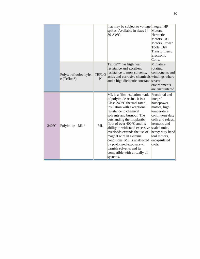
50
that may be subject to voltage spikes. Available in sizes 14 - 30 AWG.
Integral HP Motors, Hermetic Motors, DC Motors, Power Tools, Dry Transformers, Electronic Coils.
Polytetrafluoloethylene (Teflon*)
TEFLON
Teflon** has high heat resistance and excellent resistance to most solvents, acids and corrosive chemicals and a high dielectric constant.
Miniature rotating components and windings where severe environments are encountered.
240°C Polyimide - ML* ML
ML is a film insulation made of polyimide resins. It is a Class 240°C thermal rated insulation with exceptional resistance to chemical solvents and burnout. The outstanding thermoplastic flow of over 400°C and its ability to withstand excessive overloads extends the use of magnet wire in extreme conditions. ML is unaffected by prolonged exposure to varnish solvents and its compatible with virtually all systems.
Fractional and integral horsepower motors, high temperature continuous duty coils and relays, hermetic and sealed units, heavy duty hand tool motors, encapsulated coils.

51
APPENDIX C
Glossary of magnetic terms
Reluctance, R: Analogous to resistance in an electrical circuit, reluctance is related to the magnetomotive force, F, and the magnetic flux by the equation R = F/(Magnetic Flux), paralleling Ohm's Law where F is the magnetomotive force (in cgs units). Remanence, Bd: The magnetic induction that remains in a magnetic circuit after the removal of an applied magnetizing force. If there is an air gap in the circuit, the remanence will be less than the residual induction, Br. Residual Induction, Br: This is the point at which the hysteresis loop crosses the B axis at zero magnetizing force, and represents the maximum flux output from the given magnet material. By definition, this point occurs at zero air gap, and therefore cannot be seen in practical use of magnet materials. Return Path: Conduction elements in a magnetic circuit which provide a low reluctance path for the magnetic flux. Reversible Temperature Coefficient: A measure of the reversible changes in flux caused by temperature variations.
Saturation: The condition under which all elementary magnetic moments have become oriented in one direction. A ferromagnetic material is saturated when an increase in the applied magnetizing force produces no increase in induction. Saturation flux densities for steels are in the range of 16,000 to 20,000 Gauss. Search Coil: A coil conductor, usually of known area and number of turns that is used with a fluxmeter to measure the change of flux linkage with the coil.

52
Stabilization: Exposure of a magnet to demagnetizing influences expected to be encountered in use in order to prevent irreversible losses during actual operation. Demagnetizing influences can be caused by high or low temperatures, or by external magnetic fields. Temperature Coefficient: A factor, which describes the change in a magnetic property with change in temperature. Expressed as percent change per unit of temperature.
Weber: The practical unit of magnetic flux. It is the amount of magnetic flux which, when linked at a uniform rate with a single-turn electric circuit during an interval of 1 second, will induce in this circuit an electromotive force of 1 volt.