synchronous machines€¦ · web viewrotor of water wheel generator consists of salient poles....
TRANSCRIPT

Construction of
Synchronous Machines
● Consists of two sets of windings:
3 phase armature winding on the stator distributed with centres 120° apart in space
field winding on the rotor supplied by DC
● Two basic rotor structures used:
salient or projecting pole structure for hydraulic units (low speed)
Cylindrical/round rotor structure for thermal units (high speed)
● Salient poles have concentrated field windings; usually also carry damper windings on the pole face.
● Cylindrical/Round rotors have solid steel rotors with distributed windings
● Nearly sinusoidal space distribution of flux wave shape obtained by:
distributing stator windings and field windings in many slots (round rotor);
shaping pole faces (salient pole)

Types of Synchronous Machine1. Hydrogenerators : The generators which are driven by hydraulic turbines
are called hydrogenerators.These are run at lower speeds less than 1000 rpm.2. Turbogenerators: These are the generators driven by steam turbines.These generators are run at very high speed of 1500rpm or above.3. Engine driven Generators: These are driven by IC engines. These are run
at a speed less than 1500 rpm.Hence the prime movers for the synchronous generators are Hydraulic turbines, Steam
turbines or IC engines.Hydraulic Turbines:Pelton wheel Turbines:Water head 400 m and above Francis turbines:Water heads up to 380 mKeplanTurbines:Water heads up to 50 mSteam turbines: The synchronous generators run by steam turbines are called
turbogenerators or turbo alternators. Steam turbines are to be run at very high speed to get higher efficiency and hence these types of generators are run at higher speeds.
Diesel Engines: IC engines are used as prime movers for very small rated generators.

StatorThe stator is the outer stationary part of the machine, which consists of• The outer cylindrical frame called yoke, which is made either
of welded sheet steel, cast iron.• The magnetic path, which comprises a set of slotted steel
laminations called stator core pressed into the cylindrical space inside the outer frame. The magnetic path is laminated to reduce eddy currents; reducing losses and heating. CRGO laminations of0.5 mm thickness are used to reduce the iron losses.A set of insulated electrical windings are placed inside the slots of the laminated stator. In case of generators where the diameter is too large stator lamination can not be punched in on circular piece. In such cases the laminations are punched in segments. A number of segments are assembled together to form one circular laminations. All the laminations are insulated from each other by a thin layer of varnish.

Stator lamination
For a given slot mmf, reluctance offered by (i) open slots is more(ii) semi-closed slots is less and (iii) closed slots is still less. Consequently the open slots have less leakage reactance than semi-closed slots, whereas the closed slots have more leakage reactance than semi closed.The wide open type slot has the advantage of permitting easy installation of form wound coils and their easy removal in case of repair. But it has the disadvantage of distributing the air gap flux into bunches or tufts, that produces ripples in the wave of the generated emf.The semi closed type slots are better in this respect, but do not make the use of form wound coils.

The wholly closed slots do not disturb the air gap flux but● they tend increase the inductance of the windings● The armature conductors have to be threaded through,
thereby increasing initial labour and cost of winding and● They present a complicated problem of end connection.
Hence they are rarely used.

The stator winding of all synchronous generator is star connected with neutral earthed. This arrangement has the advantage that the winding has to be insulated to earth for the phase voltage and not the line voltage. Star connection also has the advantage that it eliminates all triple frequency harmonics from the line voltage.

Synchronous machines are AC machines that have a field circuit supplied by an external DC source.
In a synchronous generator, a DC current is applied to the rotor winding producing a rotor magnetic field. The rotor is then turned by external means producing a rotating magnetic field, which induces a 3-phase voltage within the stator winding.In a synchronous motor, a 3-phase set of stator currents produces a rotating magnetic field causing the rotor magnetic field to align with it. The rotor magnetic field is produced by a DC current applied to the rotor winding.
Field windings are the windings producing the main magnetic field (rotor windings for synchronous machines); armature windings are the windings where the main voltage is induced (stator windings for synchronous machines).

The rotor of a synchronous machine is a large electromagnet.The magnetic poles can be either salient (sticking out of rotor surface) or non-salient construction.
Non-salient-pole rotor: usually two- and four-pole rotors. Salient-pole rotor: four andmore poles.
Rotors are made laminated to reduce eddy current losses.

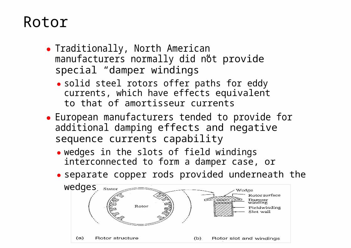
Rotor● Traditionally, North American manufacturers normally did not
provide special “damper windings”● solid steel rotors offer paths for eddy currents, which have
effects equivalent to that of amortisseur currents● European manufacturers tended to provide for additional damping
effects and negative sequence currents capability● wedges in the slots of field windings interconnected to form a
damper case, or● separate copper rods provided underneath the wedges
Solid round rotor construction

Rotor Costruction
Difference in coil spacing creates non-linear variation in flux around the rotor surface
Non-linear variation in flux around rotor surface produces sinusoidal change in the induced EMF

In case of turbo alternator the rotors are manufactured form solid steel forging. The rotor is slotted to accommodate the field winding. Normally two third of the rotor periphery is slotted to accommodate the winding and the remaining one third unslotted portion acts as the pole. Rectangular slots with tapering teeth are milled in the rotor.Generally rectangular aluminum or copper strips are employed for field windings. The field windings and the overhangs of the field windings are secured in place by steel retaining rings to protect against high centrifugal forces.Hard composition insulation materials are used in the slots which can with stand high forces, stresses and temperatures. Perfect balancing of the rotor is done for such type of rotors.

Rotor of hydraulic unit
● Normally have damper windings or amortisseurs● non-magnetic material (usually copper) rods embedded in pole face● connected to end rings to form short-circuited windings
● Damper windings may be either continuous or non-continuous● Space harmonics of the armature mmf contribute to surface
eddy current therefore, pole faces are usually laminated
Salient pole rotor construction

Salient Pole
Difference between pole face curvature and stator creates non-linear variation in flux across pole face
Non-linear variation in flux across pole face produces sinusoidal change in the induced EMF

Rotor of water wheel generator consists of salient poles. Poles are built with thin silicon steel laminations of 0.5mm to 0.8 mm thickness to reduce eddy current laminations. The laminations are clamped by heavy end plates and secured by studs or rivets. Generally rectangular or round pole constructions are used for such type of alternators. However the round poles have the advantages over rectangular poles.
Generators driven by water wheel turbines are of either horizontal or vertical shaft type. Generators with fairly higher speeds are built with horizontal shaft and the generators with higher power ratings and low speeds are built with vertical shaft design. Vertical shaft generators are of two types of designs (i) Umbrella type where in the bearing is mounted below the rotor. (ii) Suspended type where in the bearing is mounted above the rotor.
Damper Winding
Damper windings are provided in the pole faces of salient pole alternators. Damper windings are nothing but the copper or aluminum bars housed in the slots of the pole faces. The ends of the damper bars are short circuited at the ends by short circuiting rings similar to end rings as in the case of squirrel cage rotors.These damper windings are serving the function of providing mechanical balance; provide damping effect, reduce the effect of over voltages and damp out hunting in case of alternators. In case of synchronous motors they act as rotor bars and help in self starting of the motor.

Turbo alternators are normally designed with two poles with a speed of 3000 rpm for a 50 Hz frequency. Hence peripheral speed is very high. As the diameter is proportional to the peripheral speed, the diameter of the high speed machines has to be kept low. For a given volume of the machine when the diameter is kept low the axial length of the machine increases. Hence a turbo alternator will have small diameter and large axial length.However in case of water wheel generators the speed will be low and hence number of poles required will be large. This will indirectly increase the diameter of the machine. Hence for a given volume of the machine the length of the machine reduces. Hence the water wheel generators will have large diameter and small axial length in contrast to turbo alternators.

A synchronous rotor with 8 salient poles
Salient pole with field windings
Salient pole without field windings – observe laminations

Two common approaches are used to supply a DC current to the field circuits on the rotating rotor:
1. Supply the DC power from an external DC source to the rotor by means of slip rings and brushes;
2. Supply the DC power from a special DC power source mounted directly on the shaft of the machine.
Slip rings are metal rings completely encircling the shaft of a machine but insulated from it. One end of a DC rotor winding is connected to each of the two slip rings on the machine’s shaft. Graphite-like carbon brushes connected to DC terminals ride on each slip ring supplying DC voltage to field windings regardless the position or speed of the rotor.

Slip rings
Brush

● Cooling system should be provided in the generator or alternator to remove the heat generated in the windings (I2R loss) of the generator. Inability to remove the heat results in damage to the winding insulation of the generator and can lead to reduction in the life span of the generator.
● Natural air cooling and forced air cooling is provided for the small rating generators
● The slow speed salient pole alternators are ventilated by the fan action of the salient poles which provide circulating air.
● Cylindrical rotor alternators are usually long, and the problem of air flow requires very special attention.
● However for the generators rated above 60MW the amount heat generated will be enormous and air cooling is insufficient to cool the generator.

● Therefore hydrogen cooling is employed to remove the heat generated. Hydrogen cooling is chosen because of few characteristics of the hydrogen gas.
● Along with hydrogen cooling water cooling is provided in the stator winding circuit for large generators
● The cooling medium, air or hydrogen is cooled by passing over pipes through which cooling water is circulated and ventilation of the alternator.
● Liquid cooling is used for the stators of cylindrical rotor generators.

● The density of the hydrogen is 1/14th that of the air, the power required to circulate hydrogen (pumping capacity) is about 1/14thof the power required for an equivalent quantity of air. Hence the losses are reduced and the efficiency of the machine is improved by about 1% of the full load power of the machine. For example consider 500MW generator, the amount of energy saving constitutes almost 5MW which is a much more power
● Hydrogen has specific heat 14 times, heat transfer coefficient 1.5 times and thermal conductivity 7 times that of the air. So it has excellent heat carrying capacity compared to air. A generator using hydrogen as a coolant may be rated about 20% higher than the same physical size using the air
● The life of the generator is decided by the life of the winding insulation. By using hydrogen cooling which has better heat transfer coefficient, life of winding insulation increases resulting in the more life of the generator
● Smaller size of heat exchanger/cooler is required to cool the heated hydrogen

Excitation System
Excitation System is the source of field current for the excitation of a principle electric machine including means for it control.An excitation system therefore includes all of the equipment required to supply field current to excite a principle electric machine, which may be an a.c. or d.c. machine and any equipment provided to regulate or control the amount of field current delivered.
Exciter Ceiling Voltage is the maximum voltage that may be attained by an exciter with specified conditions of load. For rotating exciters, ceiling should be determined at rated speed and specified field temperature.Exciter Response is the rate of increase or decrease of the exciter voltage when a change in this voltage is demanded.

Field Flashing: The field flashing circuit is necessary when a generator is started, because of self excitation system. A DC battery is usually used as the initial excitation power supply. An AC power supply can also be adopted by means of rectifiers and a transformer.Field suppression: The de-excitation function is to reduce rapidly field energy when needed and also to separate the rotor circuit from the excitation system. The DC field circuit breaker is generally used. For better cost performance, a static field circuit breaker system can be supplied. This system reduce the field energy by reversing the excitation voltage by rectifier gate controls.Over voltage protections: The C-R absorbers and varisters are installed in each AC and DC circuit for over voltage protections of thyristor elements. In large capacitance system, a crowbar circuit is adapted on DC circuit.Excitation transformer: The excitation transformer reduces the supply voltage to the level required for excitation. A dry-type for small capacity or a oil-type for large capacity is generally used.
The ratings of Static Exciter are principally defined by the rating current and the ceiling voltage.


Slip rings and brushes have certain disadvantages: increased friction and wear (therefore, needed maintenance), brush voltage drop can introduce significant power losses. The cooling and maintenance problems associated with slip rings, brushes and commutators increases with rise in alternator ratings. Still this approach is used in most small synchronous machines.On large generators and motors, brushless exciters are used.A brushless exciter is a small AC generator whose field circuits are mounted on the stator and armature circuits are mounted on the rotor shaft. The exciter generator’s 3-phase output is rectified to DC by a 3-phase rectifier (mounted on the shaft) and fed into the main DC field circuit. It is possible to adjust the field current on the main machine by controlling the small DC field current of the exciter generator (located on the stator).
Since no mechanical contact occurs between the rotor and the stator, exciters of this type require much less maintenance.

A brushless exciter: a low 3- phase current is rectified and used to supply the field circuit of the exciter (located on the stator). The output of the exciter’s armature circuit (on the rotor) is rectified and used as the field current of the main machine.

Pilot exciter is a permanent-magnet alternator with permanent –magnet poles on the rotor and three phase armature winding on the stator. Three phase power from pilot exciter is fed to thyristor controlled bridge placed on the floor. After rectification, the controlled dc output is supplied to stationary field winding of main exciter. The three phase power, developed in the rotor of main exciter is fed through hollow shaft to the rotating silicon-diode rectifier mounted on the same shaft. The dc power from diode rectifier bridge is delivered , along the main hollow shaft, to the main alternator field without brushes and slip rings.

To make the excitation of a generator completely independent of any external power source, a small pilot exciter is often added to the circuit. The pilot exciter is an AC generator with apermanent magnet mounted on the rotor shaft and a 3-phase winding on the stator producing the power for the field circuit of the exciter.

• Completely eliminates commutator,slip rings, carbon brushes, excitor bus or cable.• Eliminates the problems of current transfer at commutator and slip rings.•The system is simple and requires practically no maintenance except for an occasional inspection.• Eliminates the hazard of changing brushes under load or the need of shutdown to change brushes.• Carbon dust is no longer produced.•Brushless system with shaft mounted pilot excitor is of self generating and the excitation is unaffected by system faults and disturbances.• Reliability is better.

A rotor of large synchronous machine with a brushless exciter mounted on the same shaft.
Many synchronous generators having brushless exciters also include slip rings and brushes to provide emergency source of the field DC current.

A largesynchronous machine with the exciterand salient poles.

By the definition, synchronous generators produce electricity whose frequency is synchronized with the mechanical rotational speed.
f=Ns P/120 where f is the electrical frequency, Hz;
Ns is mechanical speed of magnetic field (rotor speed for synchronous machine), rpm;
P is the number of poles.
Steam turbines are most efficient when rotating at high speed; therefore, to generate 50 Hz, they are usually rotating at 3000 rpm and turn 2-pole generators.Water turbines are most efficient when rotating at low speeds (200-300 rpm); therefore, they usually turn generators with many poles.

The speed and power that can be obtained from a synchronous motor or generator are limited. These limited values are called ratings of the machine. The purpose of ratings is to protect the machine from damage. Typical ratings of synchronous machines are voltage, speed, apparent power (kVA), power factor, field current and service factor.
1.Voltage, Speed, and Frequency
The rated frequency of a synchronous machine depends on the power system to which it is connected. The commonly used frequencies are 50 Hz (Europe, Asia), 60 Hz (Americas), and 400 Hz (special applications: aircraft, spacecraft, etc.). Once the operation frequency is determined, only one rotational speed in possible for the given number of poles:
Ns =120 f/P

A generator’s voltage depends on the flux, the rotational speed, and the mechanical construction of the machine. For a given design and speed, the higher the desired voltage, the higher the flux should be. However, the flux is limited by the field current.
The rated voltage is also limited by the windings insulation breakdown limit, which should not be approached closely.
Is it possible to operate a synchronous machine at a frequency other than the machine is rated for? For instance, can a 60 Hz generator operate at 50 Hz?
The change in frequency would change the speed. Since EA = K, the maximum allowed armature voltage changes when frequency changes.Specifically, if a 60 Hz generator will be operating at 50 Hz, its operating voltage must be derated to 50/60 or 83.3 %.

S 3V I AIf the rated voltage is known, the maximum accepted armature current determines the apparent power rating of the generator:
S 3V ,rated I A,max
3VL,rated IL,max
Two factors limiting the power of electric machines are1) Mechanical torque on its shaft (usually, shaft can handle much more torque)2) Heating of the machine’s winding
The practical steady-state limits are set by heating in the windings.The maximum acceptable armature current sets the apparent power rating for a generator:

The stator copper losses also do not depend on the power factor angle
P 3I 2 RSCL A A
Since the current angle is irrelevant to the armature heating, synchronous generators are rated in kVA rather than in kW.
The rotor (field winding) copper losses are:
P I 2 RRCL F F
Allowable heating sets the maximum field current, which determines the maximum acceptable armature voltage EA. These translate to restrictions on the lowest acceptable power factor:The current IA can have different angles (that depends on PF). EA is a sum of V and jXSIA. We see that, (for a constant V) for some angles the required EA exceeds its maximum value.

If the armature voltage exceeds its maximum allowed value, the windings could be damaged. The angle of IA that requires maximum possible EA specifies the rated power factor of the generator. It is possible to operate the generator at a lower (more lagging) PF than the rated value, but only by decreasing the apparent power supplied by the generator.Synchronous motors are usually rated in terms of real output power and the lowest PF at full-load conditions.Short-time operation and service factorA typical synchronous machine is often able to supply up to 150% of its rated power for a while (until its windings burn up). This ability to supply power above the rated values is used to supply momentary power surges during motor starts.It is also possible to use synchronous machine at powers exceeding the rated values for longer periods of time, as long as windings do not have time to hit up too much before the excess load is removed. For instance, a generator that could supply 1 MW indefinitely, would be able to supply 1.5 MW for 1 minute without serious harm and for longer periods at lower power levels.

The maximum temperature rise that a machine can stand depends on the insulation class of its windings.The four standard insulation classes with they temperature ratings are:
A – 600C above the ambient temperature B – 800C above the ambient temperature F – 1050C above the ambient temperature H – 1250C above the ambient temperature
The higher the insulation class of a given machine, the greater the power that can be drawn out of it without overheating its windings.
The overheating is a serious problem and synchronous machines should not be overheated unless absolutely necessary. However, power requirements of the machine not always known exactly prior its installation. Because of this, general-purpose machines usually have their service factor defined as the ratio of the actual maximum power of the machine to the rating on its plate.For instance, a machine with a service factor of 1.15 can actually be operated at 115% of the rated load indefinitely without harm.

The run-away speed is defined as the speed which the prime mover would have, if it is suddenly unloaded when working at its rated load. When the prime mover is working at full load it receives its feed ( water, steam or diesel ) corresponding to full load conditions and therefore when it is suddenly unloaded it tries to race. This is because there is no load on the prime mover while it is receiving its input corresponding to full load Steam turbine are equipped with a quick acting over speed governor set to trip at 1.1 times the rated speed and therefore the operation of the governor is reliable.

Run-away speed for turbogenerator may be set at 1.25 p.u. speed.For hydro turbines, the run away speeds are much higher (at full gate opening):• 1.8 p.u. for Pelton(impulse) turbines•2.0 to 2.2 p.u. for Francis turbines•2.5 to 2.8 .u for Kaplan (reaction) turbinesThe synchronous generators are designed to withstand mechanical stress at runaway speed. The maximum peripheral speed is about 140 to 150 m/s for salient pole synchronous generator and 175 to 180 m/s for turbo generator. The rotor diameter design is limited by this maximum peripheral speed.

Automatic Voltage Regulation (AVR)The AVR utilizes a fast response microprocessor to control its AC to DC converter power stage output that provides excitation to the generator to regulate the difference between the generator stator voltage reference set point and feedback signal to zero. Reactive power sharing during parallel operation of generator with other generators or a power system is achieved by the use of droop compensation where the voltage feedback signal is increased by typically 0% to 5% as lagging reactive load current increases from 0% to 100%. The following four operating control modes with a bumpless transfer between modes are available to suit the site requirements:• Sequence of events recording & oscillography, which is useful during commissioning diagnostics• AVR automatic voltage regulation (with switchable reactive power droop compensation for basic parallel operation)• Generator PF power factor control (for connection to large power system)• Generator VAR reactive power control (for connection to large power system)• Brushless exciter field current (manual mode) regulationOther functions of the AVR include:•Voltage soft-start build up• Minimum and maximum excitation and stator current limiters


The NGR acts to limit generator fault current to a low level when a phase-to- ground fault occurs. It also serves to protect the generator from excessively high magnetic stresses and temperatures caused by high fault currents. The NGR is time-rated.

•Partial discharge sensor kits•Bearing RTD (Resistance Temperature Detector)
•Space heater 50/60 Hz•Large oversized fabricated steel main terminal box – frame mounted•Fabricated steel neutral terminal box – frame mounted•Surge Arrestors and/or Surge Capacitors•Current and Potential Transformers•Vibration monitoring equipment•Water leakage detector•Couplings•Generator control and protection panel – optional• Medium voltage switchgear – optional

a m
MMF s 3
cKicos
c 2
3
MMF total MMF a MMF b MMF c
32 KI m
cos t s
● The mmf wave due to the three phases are:MMF
a Ki a cos
i a I m cos s t
MMF Ki cos
2 i I cos t 2
b b 3
b m s3
i l cos t 2

● Magnitude of stator mmf wave and its relative angular position with respect to rotor mmf wave depend on machine output● for generator action, rotor field leads stator field due to forward torque of
prime mover;● for motor action rotor field lags stator field due to retarding torque of shaft
load
Stator and rotor mmf wave shapes

Current paths in a round rotor
● Stator and rotor fields may:● vary in magnitude with respect to time● have different speed
● Currents flow not only in the field and stator windings, but also in:● damper windings (if present); and● solid rotor surface and slot walls of round rotor machines
