synthesis and analysis of geared five bar mechanism for ... · synthesis and analysis of geared...
TRANSCRIPT

Synthesis and Analysis of Geared Five Bar Mechanism
for Ornithopter Applications
Sandhya R, Mahesh Kadam, Dr.G.Balamurugan, H K Rangavittal
Abstract
An ornithopter is a device that imitates the flapping-wing motion of the birds. Hovering is a unique form of flapping wing flight, wherein birds float in the air without moving in any direction. It is exhibited by bees, dragonflies, hummingbirds, etc. Among these, Hummingbirds flight has a distinct characteristic that their wings can move in figure-of-eight (FO8) path. A Geared Five Bar Mechanism (GFBM) is one such potential mechanism which can generate FO8 path under certain link configuration. In this paper, a novel spatial mechanism based on a simple planar GFBM for generating spatial figure-of-eight path has been synthesized and analysed. This spatial mechanism is based on the Hummingbird morphology. Sensitivity studies have been carried out to determine the effect of various parameters of planar GFBM on the FO8 coupler curve. From the study, most sensitive parameters and conditions for generating singly symmetric FO8 coupler curve has been determined. A program has been developed to synthesise a GFBM for generating singly symmetric FO8 based on several design requirements. The most important requirements are the minimum transmission angle, bounding box requirements, symmetry of the coupler curve and rotatability criteria. The optimised planar GFBM from the program was modelled using MSC/Adams and validated analytically. The validated planar GFBM was further used for the synthesis of novel spatial mechanism, capable of generating spatial FO8 path. A wing flapping frequency up to 50 Hz has been considered for the study. Kinematic and dynamic analysis of the spatial mechanism has been carried out using MSC/Adams. The analysis has been carried out considering only the inertial loads on the linkages. The effect of aerodynamic loading is not taken into account. Keywords: Ornithopters, Hovering flight, Figure-of-eight (FO8), Geared Five Bar Mechanism (GFBM), Transmission angle, Rotatability criteria 1 Introduction
Several researchers have developed aircrafts which imitate the nature of bird’s flight. In recent years, the subject of Micro Aerial Vehicles (MAVs) propelled by flapping wings, known as ornithopter, has been an area of interest because of its practical benefits such as improved efficiency, better manoeuvrability; reduced noise compared with the rotary – driven airplanes and helicopters & resemblance to a real bird enables it to be used for intelligence and surveillance purposes [1]. ________________ Sandhya R C-CADD,National Aerospace Laboratories, Bangalore. E-mail: [email protected] Mahesh Kadam STTD, National Aerospace Laboratories, Bangalore. E-mail: [email protected] Dr.G.Balamurugan STTD, National Aerospace Laboratories, Bangalore. E-mail: [email protected] H K Rangavittal Dept of Mech Engg, B M S College of Engineering, Bangalore. E-mail: [email protected]
2nd International and 17th National Conference on Machines and Mechanisms iNaCoMM2015-218
2
Several MAVs were developed using various mechanisms. Sai.k.banala [2]
developed a compound mechanism consisting of a five bar and a four-bar mechanism to mimic an insect wing motion. Atilla Yilmaz [3] has developed a MAV capable of hovering flight, whose main focus was on the improvement in wing design and controllability for flapping motion. He considered the wing design of flies and hummingbirds. After testing of both designs, he found out that hummingbird design was advantageous over the fly design. These advantages were mainly the light weight construction and the clear defined angles of attack. Also hummingbird’s wing design generates about 75% of their lift from the down stroke and 25% from the upstroke [4]. Hence, hummingbird morphology is considered for the development of a spatial mechanism for this paper.
Zohaib [5] designed a MAV using spherical four-bar linkage. J.C Dawson et.al [6] and Cezary Galinski [7], have developed a flapping wing micro air vehicle with FO8 flapping motion using scotch-yoke mechanism as the basis. They use two degrees of flapping freedom (vertical and horizontal) in order to mimic FO8 motion. This can be achieved using a GFBM with a single degree of freedom. Thereby, reducing the number of parts and hence, the complexity. C.Zhang [8] shows that GFBM is one mechanism which generates varied FO8 coupler curves. F.Freudenstein [9], Kwun-Lon Ting [10], T.W. Lee et al. [11], G.N.Sandor [12], S.E.Rose [13] and E.P.Pollitt [14], provides an overview of properties, characteristics and methods of synthesizing the Geared five bar mechanism.
The work of presented in this paper involves, studying the feasibility of GFBM for synthesizing a flapping wing mechanism for generating a single-symmetric FO8 coupler curve based on hummingbird morphology. 1.1 Hummingbird Morphology
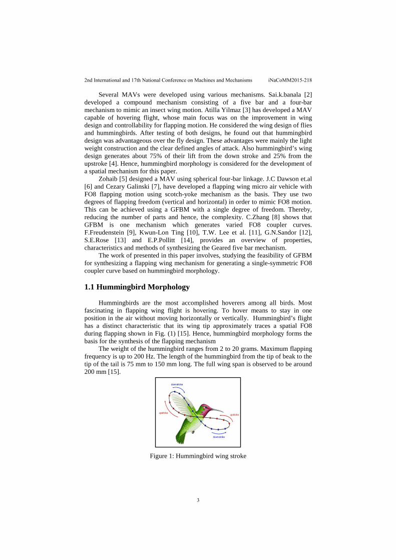
Hummingbirds are the most accomplished hoverers among all birds. Most fascinating in flapping wing flight is hovering. To hover means to stay in one position in the air without moving horizontally or vertically. Hummingbird’s flight has a distinct characteristic that its wing tip approximately traces a spatial FO8 during flapping shown in Fig. (1) [15]. Hence, hummingbird morphology forms the basis for the synthesis of the flapping mechanism
The weight of the hummingbird ranges from 2 to 20 grams. Maximum flapping frequency is up to 200 Hz. The length of the hummingbird from the tip of beak to the tip of the tail is 75 mm to 150 mm long. The full wing span is observed to be around 200 mm [15].
Figure 1: Hummingbird wing stroke
2nd International and 17th National Conference on Machines and Mechanisms iNaCoMM2015-218
3

Figure 2: A Typical GFBM
1.2 Gear Five Bar Mechanism (GFBM) Four-bar, slider-crank, geared five bar mechanism, etc., are some of the few
mechanisms which are capable of generating FO8 coupler curve. However, Geared five bar mechanism is one such mechanism which generates varied configurations of FO8 coupler curve. Hence, a geared five bar mechanism was considered for this paper.
A GFBM Fig. (2) is basically a five bar linkage with two input angles related by a linear gearing constraint identified by the gear ratio and phase angle, as mentioned in the linear equation below [10]:
θo = λθi + φ
Where, Input crank angle – ɵi, Output crank angle – ɵo Gear ratio – λ Phase angle between gears – φ
In general, adding a link and corresponding joint to a four bar linkage forms a five bar linkage having two degrees of freedom as shown in the Fig. (3). But by adding a gear constraint to this five bar linkage (where a pair of gears tie the two links with a new half joint), a two degree of freedom five bar linkage becomes a single degree of freedom mechanism [16, 10].
Figure 3: Comparison between five bar (2 DOF)
and GFBM (1DOF) mechanism
GFBM provides better transmission characteristics, has a greater range of input and output rotation than pivoted linkages, control of mechanical advantage can also be achieved, provides favourable transmission angle and also rotations of input and output elements can be correlated [12]. GFBM are used as shaking machines for
2nd International and 17th National Conference on Machines and Mechanisms iNaCoMM2015-218
4

vibration testing, straight line mechanism, steering mechanism, multiple-dwell mechanism without cams, etc.
Hence this paper aims at study of feasibility of planar GFBM for synthesizing a flapping wing mechanism based on Hummingbird morphology, in order to generate a single-symmetric FO8 coupler curve. Further, a spatial mechanism configuration has been developed based on planar GFBM, to generate spatial FO8 wing stroke which will initially serve as an aeromechanical test bed, which can be further developed to a flight worthy model. 2. Methodology The solution to the problem has been achieved in two phases:
• Synthesis and analysis of planar GFBM for generating single-symmetric FO8.
• Synthesis of a mechanism to generate a spatial FO8, based on the planar GFBM and its analysis.
In order to synthesize a GFBM generating symmetric FO8 coupler curve, a sensitivity study of different parameters of GFBM that affects the FO8 path and its symmetry was carried out. The results from the sensitivity study was implemented in a program for synthesizing various planar GFBM capable generating symmetric FO8.This program checks for symmetry of FO8 generated by each mechanism and also transmission angles of each mechanism is maintained within a specific range (i.e., 400 ≤µ≤900). From the program output, an optimum configuration of a planar GFBM was selected. Kinematic analysis of this optimum configuration was carried out analytically and verified using MSC/Adams software. Finally, a spatial mechanism based on this planar GFBM was built using Solid Works and analysed in MSC/Adams software.
2.1 Design requirements
• The planar mechanism has to be Class I kinematic chain according to Ting`s criteria of rotatability (i.e., the two shortest links can revolve fully with respect to other links).
• The mechanism has to be an open configuration. • The crank length has been constrained to 15 mm, due to practical
considerations. • The fixed link (i.e., the distance between the gear centres) cannot be beyond
50 mm, to satisfy bounding box requirements. • The range of transmission angle for a mechanism operating for efficient
force transmission is 400 ≤µ≤900. • The spatial mechanism should fit within a bounding box of 100mm x
100mm (typical aeromechanical test bed).
2nd International and 17th National Conference on Machines and Mechanisms iNaCoMM2015-218
5
2.2 Synthesis and Analysis of Planar GFBM for Generating Single-Symmetric FO8
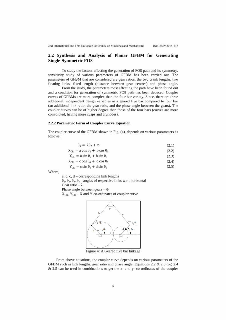
To study the factors affecting the generation of FO8 path and its symmetry, sensitivity study of various parameters of GFBM has been carried out. The parameters of GFBM that are considered are gear ratios, the two crank lengths, two floating links, fixed length (distance between gear centres) and phase angle. From the study, the parameters most affecting the path have been found out and a condition for generation of symmetric FO8 path has been deduced. Coupler curves of GFBMs are more complex than the four bar variety. Since, there are three additional, independent design variables in a geared five bar compared to four bar (an additional link ratio, the gear ratio, and the phase angle between the gears). The coupler curves can be of higher degree than those of the four bars (curves are more convoluted, having more cusps and crunodes). 2.2.2 Parametric Form of Coupler Curve Equation The coupler curve of the GFBM shown in Fig. (4), depends on various parameters as follows:
θ5 = λθ2 + φ
(2.1) XCR = a cos θ2 + b cos θ3
(2.2)
YCR = a sin θ2 + b sin θ3
(2.3) XCR = c cos θ4 + d cos θ5
(2.4)
YCR = c sin θ4 + d sin θ5
(2.5)
Where, a, b, c, d – corresponding link lengths θ2, θ3, θ4, θ5 – angles of respective links w.r.t horizontal Gear ratio – λ Phase angle between gears – ∅ XCR, YCR – X and Y co-ordinates of coupler curve
Figure 4: A Geared five bar linkage
From above equations, the coupler curve depends on various parameters of the
GFBM such as link lengths, gear ratio and phase angle. Equations 2.2 & 2.3 (or) 2.4 & 2.5 can be used in combinations to get the x- and y- co-ordinates of the coupler
2nd International and 17th National Conference on Machines and Mechanisms iNaCoMM2015-218
6
curve. A sensitivity study was performed varying each parameter of the GFBM erstwhile keeping the rest of them constant. Coupler curve generated though these variations was plotted and studied further to determine the parameters affecting the FO8 generation. A condition was established for generation of single-symmetric FO8 based on the sensitivity studies.
With reference to Z N H atlas [9] for GFBM coupler curves, a symmetrical GFBM is considered as the basis for this investigation. A symmetrical GFBM is one which has equal cranks and equal floating links. Sensitivity studies of symmetrical GFBM have been carried out for gear ratios of ±2 and ±1.
For this study a symmetrical GFBM with cranks of 25mm, floating links of 55 mm and fixed link of 55 mm has been considered. Initially for each gear ratio, effect of varying the fixed link length (centre distance between gears) and the phase angle (angle between the gears) has been studied to evaluate its effect on the generated coupler curve. Gear ratios ±2 produces a multi-loop coupler curve and the curve is asymmetrical. The curve pattern does not change with the variation of parameters. A gear ratio of +1 produces a single-loop coupler curve. It has no crunodes. The coupler curve obtained is single symmetric. Varying fixed link length and phase angle makes the coupler curve asymmetric.
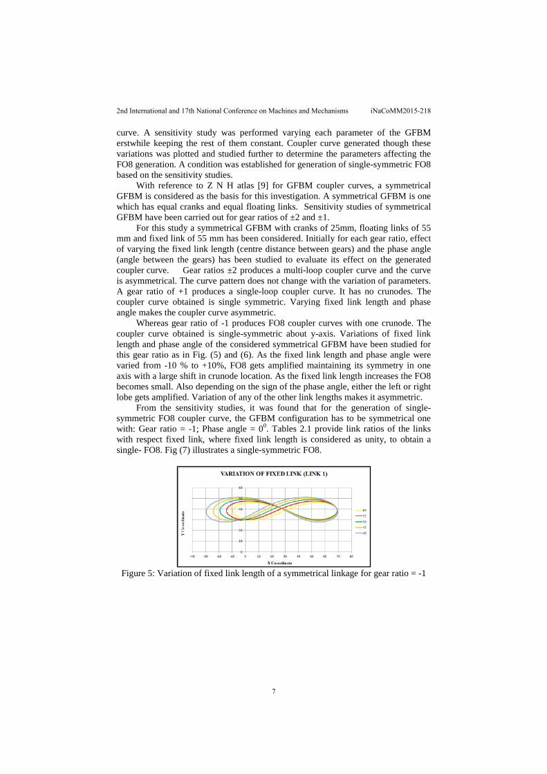
Whereas gear ratio of -1 produces FO8 coupler curves with one crunode. The coupler curve obtained is single-symmetric about y-axis. Variations of fixed link length and phase angle of the considered symmetrical GFBM have been studied for this gear ratio as in Fig. (5) and (6). As the fixed link length and phase angle were varied from -10 % to +10%, FO8 gets amplified maintaining its symmetry in one axis with a large shift in crunode location. As the fixed link length increases the FO8 becomes small. Also depending on the sign of the phase angle, either the left or right lobe gets amplified. Variation of any of the other link lengths makes it asymmetric.
From the sensitivity studies, it was found that for the generation of single-symmetric FO8 coupler curve, the GFBM configuration has to be symmetrical one with: Gear ratio = -1; Phase angle = 00. Tables 2.1 provide link ratios of the links with respect fixed link, where fixed link length is considered as unity, to obtain a single- FO8. Fig (7) illustrates a single-symmetric FO8.
Figure 5: Variation of fixed link length of a symmetrical linkage for gear ratio = -1
2nd International and 17th National Conference on Machines and Mechanisms iNaCoMM2015-218
7

Figure 6: Variation of phase angle of a symmetrical linkage for gear ratio = -1
Table 1: Configuration for generating single-symmetric FO8
Figure 7: A single-symmetric FO8
2.3 Program for Synthesizing and Analyzing GFBM
A program for synthesizing the GFBMs for generating single-symmetric FO8, based on the design requirements was developed. This program checks for symmetry of FO8 generated by each mechanism and also checks transmission angles of each mechanism (i.e., to be within range of 400 ≤ μ ≥ 900). From the output of this program, an optimum configuration of a GFBM was selected. Analysis of this mechanism was carried out with the available relations [16].
An optimum configuration was chosen from the program output. Kinematic characteristics of this configuration evaluated analytically and verified using MSC/Adams. The analytical results and the Adams results were compared with each other and were found to be in good agreement with each other. The errors in results were found to be within less than 0.3%.
Sl. No Link Nomenclature
Link Ratio With Respect To Fixed Link
1 FIXED LINK 1.00 2 CRANK_1 0.40 3 FLOATING LINK_1 1.00 4 FLOATING LINK_2 1.00 5 CRANK_2 0.40
2nd International and 17th National Conference on Machines and Mechanisms iNaCoMM2015-218
8

3. Synthesis and Analysis of Spatial Mechanism for FO8 Path Generation
Hummingbird flapping wing for MAV traces a spatial FO8, which is a three dimensional motion. Hence, a spatial mechanism has been developed based on planar GFBM, to generate single-symmetric spatial FO8 wing stroke. A planar GFBM is chosen to generate required single-symmetric FO8 and then converted to a spatial FO8. This configuration can initially serves as an aeromechanical test bed. With further development, an attempt can be made to build flight worthy model. 3.1. Salient features of the spatial mechanism
The spatial mechanism was built on the basis of the planar GFBM that generates a single-symmetric FO8 as shown in Fig. (8) and (9). A planar FO8 generated by GFBM is converted to a spatial FO8 by adding an out-of plane extension link and wing on either sides of the coupler point, hence, wing tip traces a spatial FO8. The link configuration is as follows: Link 1 – base link, Link 2 & 5 – two cranks, Link 3 & 4 – two floating links, Link 6 & 7 – sliding rod and Link 8 & 9 – wing. The coupler point that generates the planar single-symmetric FO8 houses a universal joint as in Fig. (10). Either side of the universal joint there is a cylinder which hosts a sliding rod that is connected to the spherical joint. These sliding rods are then connected to the wing through a spherical joint that is housed in the body of the mechanism (bounding box). This arrangement allows by transmitting x and y displacement of the coupler point through universal joint and z-displacement of the coupler curve through the spherical joint, thus converting the planar curve to a spatial FO8. The whole mechanism is symmetric about the basic GFBM.
Figure 8: Isometric view of the Figure 9: Front View of the
spatial mechanism spatial mechanism
Figure 10: A closer view of the Universal joint and the wing
The analysis of spatial mechanism was carried out completely using Adams
software. A frequency of 50 Hz is considered for the analysis. The torque and power consumption for the mechanism are estimated for the frequency of 50 Hz.
2nd International and 17th National Conference on Machines and Mechanisms iNaCoMM2015-218
9

4. Results and Discussion
From the program output, a link configuration with crank lengths - 16 mm, floating link lengths – 40.64 mm and distance between the gear centres – 46 mm was selected as it provides maximum transmission angle of 87.190, has a line of symmetry with respect to y-axis and span & width of the FO8 generated is 50.58 mm and 9.339 mm. Also this configuration fits completely within the bounding box.
The peak and RMS value of the input torque was found to be 0.238 N-m and 0.205 N-m respectively as shown in Fig. (11). Also the peak and RMS value of power consumption was found to be 74.72 Watts and 64.45 Watts respectively indicated in Fig. (12). A variable torque motor running at a constant speed of 314.16 rad/sec is the input required for the mechanism.
In comparison with the power consumed by the spatial mechanism generated using four-bar (around 165.8 Watts), the geared five bar mechanism consumes less power for the same frequency of 50 Hz [17].
Figure 11: Motor torque
Figure 12: Power consumption
5. Conclusion
A spatial mechanism for generating a single-symmetric FO8 path generation for ornithopter application was synthesized. Kinematic and dynamic analysis was carried out to determine joint forces and torque on motor considering a frequency of 50Hz. The RMS value of input torque of 0.205 N-m and power of 64.45 Watts has been estimated.
2nd International and 17th National Conference on Machines and Mechanisms iNaCoMM2015-218
10

6. References
[1] www.ornithopter.org [2] Sai K. Banala, Sunil K. Agrawal, “Design and Optimization of a
Mechanism for Out-of-Plane Insect Wing like Motion With Twist”, Journal of Mechanical Design, JULY 2005, Vol. 127, pp.841-844
[3] Attila Yilmaz, “Design and Development of a Flapping Wing Micro Air-Vehicle”, Master-Thesis, Swiss Federal Institute of Technology, Zurich, Oct 09-Apr-11.
[4] http://people.eku.edu/ritchisong/554notes3.html [5] Zohaib Parvaiz Rehmat, “Design of Figure-8 Speherical Motion Flapping
Wing for Miniature UAVs”, Master of Science Degree in Mechanical Engineering, University of Nevada, Las Vegas, May 2009.
[6] J.C.Dawson and P.G.Huang, “Figure-8 Flapping Micro Air Vehicle”, 49th AIAA Aerospace Sciences Meeting Including the New Horisons Forums and Aerospace Exposition, 4-7 January 2011,Orlando,Florida.
[7] Cezary Galinski and Rafał Z˙bikowski, “Insect-like flapping wing mechanism based on a double spherical Scotch yoke”, J. R. Soc. Interface (2005) 2, 223–235, 18 May 2005.
[8] C.Zhang, R.L.Norton, P.E and T.Hammond, “Optimisation of parameters for specified path generation using atlas of coupler curves of Geared five bar linkages”, Mechanism and Machine Theory, Vol.19,No.6,pp459-466,1984.
[9] F.Freudenstein and E.J.F.Primose, “Geared five bar motion-Part 1, Gear ratio minus one”,J.Appl.Mech.30.Trans.ASME Series E,85,161(1963)
[10] Kwun-Lon Ting, “Mobility Criteria for Geared five bar Linkages”, Mechanism and Machine Theory, Vol.29, No.2, pp 251-264,1994.
[11] Ting.W.lee and F.Freudenstein, “Design of geared 5-Bar Mechanism for unlimited crank rotations and optimum transmission”, Mechanism and Machine Theory, Vol.13, pp235-244, 1979.
[12] Sandor.G.N and Wilt.D.R, “Synthesis of a geared four bar mechanism”, Seconf international congress on the Theory of Machines and Mechanisms, Zakopane, Poland, Sept 24-27, 1969.
[13] S.E.Rose, “Five bar loop synthesis”, Machine Design, Vol.33, 189, 1961. [14] E.P.Pollitt, “Five bar linkages with two drive cranks”, Machine Design,
34, 168, 1962. [15] www.worldofhummingbirds.com [16] Robert L.Norton, Design of machinery, Mc Graw hill. [17] Manasa.M.V, “Study of Flapping wing mechanisms for ornithopter
applications”, M.Tech Thesis, Visvesvaraya Technological University, Belgaum, Karnataka, India, July 2013.
2nd International and 17th National Conference on Machines and Mechanisms iNaCoMM2015-218
11