synthesis, characterization and performance of
TRANSCRIPT

SYNTHESIS, CHARACTERIZATION AND PERFORMANCE OF
POLYSULFONE/CELLULOSE ACETATE PHTHALATE/ POLYVINYLPYRROLIDONE (PSf/CAP/PVP) BLEND
ULTRAFILTRATION MEMBRANES
ASMADI BIN ALI @ MAHMUD
Thesis submitted in fulfillment of the requirements for the award of the degree of
Doctor of Philosophy in Chemical Engineering
Faculty of Chemical & Natural Resources Engineering UNIVERSITI MALAYSIA PAHANG
JULY 2013

ii
SUPERVISOR’S DECLARATION
I hereby declare that I have checked this thesis and in my opinion, this thesis is adequate
in terms of scope and quality for the award of the degree of Doctor of Philosophy in
Chemical Engineering.
Signature
Name of Supervisor : PROFESSOR DATO’ DR ROSLI BIN MOHD YUNUS
Position : PROFESSOR
Date :
iii
STUDENT’S DECLARATION
I hereby declare that the work in this thesis is my own except for quotations and
summaries which have been duly acknowledged. The thesis has not been accepted for
any degree and is not concurrently submitted for award of other degree.
Signature
Name : ASMADI BIN ALI @ MAHMUD
ID Number : PKC 07003
Date :
iv
DEDICATION
To my mother, late farther, wife, and kids..
v
ACKNOWLEDGEMENTS
First and foremost, I would like to extend my deep sense of gratitude to my supervisor,
Professor Dato’ Dr Rosli bin Mohd Yunus for his invaluable assistance and guidance,
constant dedication as well as endless encouragement throughout my study at UMP.
My special thanks to my friends namely Dr Mohamad Awang, Dr Sofiah Hamzah and
Dr Abdul Rahman Hassan for the meaningful discussion, suggestion and their effort to
review the manuscript.
I am also thankful to technical staffs of Faculty of Chemical Engineering and Natural
Resources, UMP and Department of Engineering Science, Faculty of Science and
Technology, UMT for their helping hands and co-operations. My humble regards to
others whose names are not mentioned here for their munificence and assistance.
I would like to thank all members of Postgraduate Club especially Azharin, Haizal and
Mulyadi. Nice knowing all of you and we will meet again in future, insyaAllah. Last but
not least, I wish to thank my beloved wife, Norazfani and my children, Nur Fatima
Zahra and Nurina, without their support I would never have succeeded. Their love
provided my inspiration and was my driving force.

vi
ABSTRACT
Polysulfone (PSf) is an important class polymer that has been most widely used in the manufacture of synthetic asymmetric ultrafiltration membranes. However, the main disadvantage of PSf membrane is due to its hydrophobic characteristic which in turn fouled the membranes. In practical application of UF systems, membrane fouling is a serious problem that causes high cost energy, operation, and maintenance. Polymer blend is a simple and an efficient method for designing new materials to improve performance of the hydrophobic membranes. The polymer blend is a proven tool to obtain new types of UF membrane, which has better hydrophilicity compared to the original membranes. Cellulose acetate phthalate (CAP) is one of the potential hydrophilic organic polymers that can be used and explored in PSf polymer blend technique to improve hydrophilicity and performance of PSf membranes. PSf/CAP blend membranes with blend composition of 95/5, 90/10, 85/15 and 80/20 wt% of total polymer concentration in the membrane casting solutions were developed via wet phase inversion process. The effect of CAP composition on characteristics, morphology and performance of PSf/CAP blend membranes were investigated. The hydrophilicity of the PSf/CAP blend membranes were improved evidently by blending with CAP. Based on BSA protein separation performance study, the PSf/CAP blend ultrafiltration membrane which contains 10 wt% of CAP shows the best performance membrane due to its high productivity and separation performance as well as it has good membrane characteristics in terms of high hydrophilicity properties, pore properties and membrane morphological structure. The effect of polyvinylpyrrolidone (PVP) additives in the range of 1 to 5 wt% on the best PSf/CAP blend membranes was studied. The results revealed that an addition of 1 to 3 wt% of PVP additive formed membrane with small average pore size and low MWCO due to the strong interpenetrating network between PSf-CAP-PVP and consequently increased protein rejections. Further increment of PVP additive promoted PVP leached out during wet phase inversion process and formed membranes with big pore size and high MWCO. These membranes had high permeate flux but low rejection of proteins. The PSf/CAP/PVP blend membrane that contains 3 wt% of PVP was selected as the best high performance membrane. Further, there were five different shear rates (42.0, 52.5, 70.0, 105.0 and 210.0 s-1) applied during fabrication process of PSf/CAP/PVP blend membranes by using the best PSf/CAP/PVP dope formulation. The experimental results showed that an increase in shear rate from 42.0 to 105.0 s-1 decreased the water content, porosity and permeability of the membranes. Further increment of shear rate to 210.0 s-1 increased the water content, porosity and permeability of the membranes due increased in porous structure of PSf/CAP/PVP membrane and a decrease in membrane thickness. In terms of BSA separation performance, the PSf/CAP/PVP blend membranes fabricated at the shear rate of 105.0 s-1 showed the best performance due to high rejection of BSA at favorable permeation flux of BSA protein solution. In an evaporation time study, the PSf/CAP/PVP blend membranes fabricated at shear rate of 105.0 s-1 were introduced to evaporation time of 5, 10, 15 and 20 s before immersed in a coagulation bath. The results showed that the effects of evaporation time significantly changed the properties and morphological structures of the PSf/CAP/PVP blend membranes. In this experiment study, PSf/CAP/PVP blend membrane which was fabricated at evaporation time of 10 s exhibited the best performance membrane due to high membrane productivity and separation ability.

vii
ABSTRAK
Polisulfon (PSf) adalah polimer yang penting digunakan dalam pengeluaran membran ultraturasan (UF) asimetrik sintetik. Walaubagaimanapun, kelemahan utama membran PSf adalah ciri hidrofobiknya yang menyebabkan kotoran membran. Secara praktiknya, kotoran membran adalah satu masalah yang sangat serius kerana ia menyebabkan kos tenaga, operasi dan penyelenggaraan yang tinggi. Adunan polimer adalah kaedah paling mudah dan cekap untuk mendapatkan bahan baharu bagi mempertingkatkan prestasi membran hidrofobik. Adunan polimer terbukti sebagai satu cara untuk menghasilkan membran UF baharu yang mempunyai sifat hidrofilik lebih baik berbanding membran asal. Selulosa asetat phthalate (CAP) adalah salah satu polimer organik hidrofilik berpontensi yang boleh digunakan dalam teknik adunan dengan PSf bagi meningkatkan sifat hidrofilik dan prestasi membran PSf. Membran adun PSf/CAP dengan komposisi adunan 95/5, 90/10, 85/15 dan 80/20 wt% dari kepekatan keseluruhan polimer dalam larutan tuang membran dibangunkan melalui proses penyongsangan fasa basah. Kesan komposisi CAP ke atas ciri-ciri, morfologi dan prestasi membran adun PSf/CAP dikaji. Sifat hidrofilik membran adun ini terbukti meningkat dengan mengadunkan CAP. Berdasarkan kajian prestasi pemisahan protein BSA, membran adun PSf/CAP yang mengandungi 10 wt% kandungan CAP dipilih sebagai membran yang terbaik kerana menunjukan produktiviti dan pemisahan yang tinggi di samping ciri yang baik bagi sifat hidrofilik, sifat liang dan struktur morfologi. Kesan bahan tambah polivinilpirolidon (PVP) dalam julat 1 hingga 5 bt% ke atas membran adun PSf/CAP terbaik dikaji. Keputusan menunjukkan penambahan 1 hingga 3 wt% bahan tambah PVP membentuk membran bersaiz purata liang dan MWCO yang kecil kerana rangkaian saling jalinan yang kuat antara PSf-CAP-PVP dan seterusnya meningkatkan pemisahan protein. Penambahan seterusnya bahan tambah PVP akan menyebabkan PVP melarut resap semasa proses penyongsangan fasa basah dan membentuk membran bersaiz purata liang dan MWCO yang besar. Membran ini mempunyai aliran telapan yang tinggi tetapi pemisahan protein yang rendah. Membran adun PSf/CAP/PVP yang mengandungi 3 wt% PVP dipilih sebagai membran prestasi terbaik. Selanjutnya, lima kadar ricih yang berbeza (42.0, 52.5, 70.0, 105.0 and 210.0 s-1) digunakan dalam proses pembikinan membran adun PSf/CAP/PVP menggunakan formulasi dop PSf/CAP/PVP yang terbaik. Keputusan ujikaji menunjukkan peningkatan kadar ricih dari 42.0 ke 105.0 s-1 menurunkan kandungan air, keporosan dan ketelapan membran. Peningkatan kadar ricih ke 210.0 s-1 meningkatkan kandungan air, keporosan dan ketelapan membran kerana peningkatan keporosan struktur membran dan penurunan ketebalan membran. Membran adun PSf/CAP/PVP yang dibikin pada kadar ricih 105.0 s-1 menunjukkan prestasi terbaik dengan pemisahan BSA yang tinggi pada aliran yang sesuai. Dalam kajian masa penyejatan, membrane adun PSf/CAP/PVP yang dibikin pada kadar ricih 105.0 s-1 didedahkan dengan masa penyejatan selama 5, 10, 15 dan 20 s sebelum direndamkan ke dalam sebuah rendaman penggumpalan. Keputusan menunjukkan kesan masa penyejatan secara signifikan merubah sifat-sifat dan struktur morfologi membran adun PSf/CAP/PVP. Dalam ujikaji ini, membran adun PSf/CAP/PVP yang dibikin pada masa penyejatan selama 10 s menunjukkan membran prestasi terbaik dengan produktiviti dan pemisahan yang tinggi.
viii
TABLE OF CONTENTS
Page
SUPERVISOR’S DECLARATION ii
STUDENT’S DECLARATION iii
DEDICATION iv
ACKNOWLEDGEMENTS v
ABSTRACT vi
ABSTRAK vii
TABLE OF CONTENTS viii
LIST OF TABLES xii
LIST OF FIGURES xiv
LIST OF SYMBOLS xvii
LIST OF ABBREVIATIONS xix
CHAPTER 1 INTRODUCTION
1.1 Overview 1
1.2 Asymmetric Membrane 3
1.3 Membrane Technology 4
1.4 Problem Statement 6
1.5 Objectives 10
1.6 Scopes 10
1.7 Overview of the Thesis 11
CHAPTER 2 LITERATURE REVIEW
2.1 Membrane 13
2.2 Membrane Separation Processes 14
2.3 Chronological of Ultrafiltration Development 17
2.4 Ultrafiltration Membranes 19
2.4.1 Materials of Ultrafiltration Membranes 23

ix
2.4.2 Formation of Ultrafiltration Membranes: Phase Inversion Process 25
2.5 Transport Mechanisms of Ultrafiltration Membrane 27
2.5.1 Measurement of Pore Size by the Hagen-Poiseuille Equation 30
2.6 Fouling of Ultrafiltration Membranes 30
2.7 Ultrafiltration Blend Membranes 33
2.8 Polysulfone Blend Membrane 38
2.9 Additives in Blend Membranes 43
2.10 Shear Rate 45
2.11 Evaporation Time 48
2.12 Characterization of Ultrafiltration Membrane 50
2.12.1 Water Content and Contact Angle 51 2.12.2 Molecular Weight Cut-Off and Pore Properties 52 2.12.3 Surface Characterization 55
2.13 Rheological Properties 55
CHAPTER 3 MATERIALS AND METHODOLOGY
3.1 Introduction 58
3.2 Work Flow of Research 59
3.3 Materials 60
3.3.1 Polymers 61 3.3.2 Sovent and Non-Solvent 63 3.3.3 Additives 65
3.4 Membrane Preparation 65
3.5 Membrane Synthesis 68
3.6 Shear Rate 69
3.7 Evaporation Time 70
3.8 Membrane Performance Tests 71
3.8.1 Pure Water Permeation 73 3.8.2 Protein Separation Performance 75
3.9 Membrane Characterization 76
3.9.1 Water Content 76 3.9.2 Porosity 77 3.9.3 Contact Angle 77
3.9.4 Scanning Electron Microscopy (SEM) 77 3.9.5 Molecular Weight Cut-off and Pore Properties 79
x
CHAPTER 4 RESULTS AND DISCUSSION
4.1 Polysulfone (PSf) and Polysulfone/Cellulose Acetate Phthalate 80 (PSf/CAP) Blend Membranes
4.1.1 Water Content and Contact Angle 81 4.1.2 Membrane Morphology 83 4.1.3 Pure Water Permeation 86 4.1.4 Membrane Permeability Coefficient and Porosity 90 4.1.5 Protein Separation Performance 92 4.1.6 Molecular Weight Cut-Off 96 4.1.7 Pore Properties 97
4.2 Effects of Polyvinylpyrrolidone (PVP) as an Additive 99 in PSf/CAP/PVP Blend Membranes
4.2.1 Water Content and Contact Angle 100 4.2.2 Membrane Morphology 102 4.2.3 Pure Water Permeation 104 4.2.4 Membrane Permeability Coefficient and Porosity 108 4.2.5 Protein Separation Performance 109 4.2.6 Molecular Weight Cut-Off and Pore Properties 115
4.3 Effects of Shear Rate on PSf/CAP/PVP Blend Membranes 118
4.3.1 Water Content and Porosity 119 4.3.2 Pure Water Permeation 120 4.3.3 Membrane Permeability Coefficient 122 4.3.4 Membrane Morphology 123 4.3.5 Protein Separation Performance 125 4.3.6 Molecular Weight Cut-Off and Pore Properties 129
4.4 Effects of Evaporation Time on PSf/CAP/PVP Blend Membranes 132
4.4.1 Water Content and Porosity 133 4.4.2 Pure Water Permeation and Membrane Permeability Coefficient 134 4.4.3 Membrane Morphology 137 4.4.4 Protein Separation Performance 140 4.4.5 Molecular Weight Cut-Off and Pore Properties 144

xi
CHAPTER 5 CONCLUSION AND RECOMMENDATIONS
5.1 Conclusion 148
5.1.1 Conclusion on Polysulfone (PSf) and Polysulfone/Cellulose 148 Acetate Phthalate (PSf/CAP) Blend Membranes Study
5.1.2 Conclusion on the Effects of Polyvinylpyrrolidone (PVP) 149 as an Additive in PSf/CAP/PVP Blend Membranes Study
5.1.3 Conclusion on the Effects of Shear Rate on 150 PSf/CAP/PVP Blend Membranes Study
5.1.4 Conclusion on the Effects of Evaporation Time on 151 PSf/CAP/PVP Blend Membranes Study
5.2 Recommendations 152
REFERENCES 155
APPENDICES 173
A Calculations and Measurements of Raw Data Samples 174
B List of Publications 183

xii
LIST OF TABLES
Table No. Title Page
2.1 Characteristics of membranes used in different membrane 15
separation processes 2.2 Characteristics of retentate and permeate in different membrane 16
processes 2.3 Milestone in the development of ultrafiltration 20 2.4 Commercial available hydrophilic and hydrophobic 23
polymers for membrane production 2.5 Advantages and disadvantages of phase inversion polymeric 24
membranes in water industries 2.6 Polymer blend membranes 35 3.1 Formulation of PSf and PSf/CAP blend casting solutions 66
3.2 Formulation of PSf/CAP/PVP blend casting solutions 67 3.3 Membrane code for PSf/CAP/PVP blend membranes fabricated 70 at different shear rates 3.4 Membrane code for PSf/CAP/PVP blend membranes fabricated 71 at different evaporation time 4.1 Water content and contact angle of PSf and PSf/CAP blend membranes 81 4.2 Membrane permeability coefficient and porosity of PSf and 91
PSf/CAP blend membranes 4.3 MWCO and pore properties of PSf and PSf/CAP blend membranes 96 4.4 Water content and contact angle of PSf/CAP/PVP blend membranes 100
at various concentrations of PVP 4.5 Membrane permeability coefficient of PSf/CAP/PVP blend membranes 108
containing different PVP concentrations 4.6 MWCO and pore properties of PSf/CAP/PVP blend at 115 different PVP concentration 4.7 Rheological parameters of the PSf/CAP/PVP blend fabrication process 118

xiii
4.8 Effects of shear rates on water content and porosity 119 of PSf/CAP/PVP blend membranes
4.9 Membrane permeability coefficient of PSf/CAP/PVP membrane 122
fabricated at different shear rates 4.10 MWCO and structural properties of PCS membranes 129 4.11 Effects of evaporation time on water content and porosity 134
of PSf/CAP/PVP blend membranes 4.12 Membrane permeability coefficient of PCE membranes 136 4.13 MWCO and pore properties of PCE membranes 145
A.1 Rheological parameters of the PSf/CAP/PVP blend fabrication process 174 A.2 Raw data of water content for PC-10 membrane 175 A.3 Raw data of porosity for PC-10 membrane 176 A.4 Raw data of pure water flux for PC-10 membrane at 5 bar 177 A.5 Raw data of permeate flux of BSA for PC-10 membrane at 3 bar 178 A.6 Raw data of BSA concentrations in feed and permeate for 179 PC-15 membrane at 3 bar
A.7 Raw data to calculate the surface porosity of the PC-15 membrane, ε 182 A.8 Raw data to calculate the pore density of PC-15 membrane, n 182

xiv
LIST OF FIGURES
Figure No. Title Page
2.1 Asymmetric membrane structure 20 2.2 Separation by ultrafiltration membrane 22 2.3 Schematic representation of phase inversion processes: 25
(a) dry phase inversion (b) wet phase inversion (c) dry/wet phase inversion
2.4 Triple component-dual phase separation for membrane production 27 2.5 Some characteristic pore geometries found in membranes: 28 (a) Parallel cylindrical pore (b) close packed spheres (c) a sponge-like structure 2.6 Overview of various types of resistance towards mass transport 32 across a membrane in pressure driven processes
2.7 The effect of the equilibrium contact angle, θ, on the pore intrusion 52
phenomenon 2.8 Relation between solute molecular weight and the average pore radius 54
of the upstream surface of the membrane at 80, 85, and 95% solute retention levels 2.9 Apparent viscosity – shear rate curves for three fluids which the same 56
apparent viscosity at zero shear rate 3.1 Work flow of research 59 3.2 Polysulfone polymer structure 61 3.3 Polymer structure of cellulose acetate phthalate 62 3.4 Molecular Structure of N-Methyl-2-Pyrrolidone 64 3.5 Schematic diagram of apparatus used for preparation of 68
polymer casting solution 3.6 A high precision casting machine 69 3.7 Dead-end permeation cell 72 3.8 Schematic diagram of dead-end UF filtration set-up 73

xv
3.9 A full set of scanning electron microscope (SEM) 78 4.1 SEM micrograph of cross sectional view of PSf and PSf/CAP blend 84
membranes; (a) PC-0; (b) PC-5; (c) PC-10; (d) PC-15; (e) PC-20 4.2 Effect of CAP composition on pure water fluxes of the compacted PSf 87 and PSf/CAP blend membranes at operating pressure of 5 bar 4.3 Pure water flux of PSf and PSf/CAP blend membranes at different 89
operating pressure
4.4 Permeate fluxes of different molecular weight of proteins for PSf and 92 PSf/CAP blend membranes at operating pressure of 3 bar 4.5 Rejection of different molecular weight of proteins for PSf and PSf/CAP 94 blend membranes at operating pressure of 3 bar
4.6 Effect of CAP content on permeate flux and rejection of BSA protein 95 solution 4.7 Cross section of membrane morphology of PSf/CAP/PVP blend various 103
membranes at concentrations of PVP additive; (a) PCV-0 (b) PCV-1 (c) PCV-2 (d) PCV-3 (e) PCV-4 (f) PCV-5
4.8 Effect of PVP concentration on pure water permeation of the compacted 106 PSf/CAP/PVP blend membranes at an operating pressure of 5 bar 4.9 Pure water flux of PSf/CAP/PVP membranes contained different 107
concentrations of PVP additives at different operating pressures 4.10 Permeate fluxes of different molecular weight of proteins for 110
PSf/CAP/PVP blend membranes containing different PVP concentrations at an operating pressure of 3 bar 4.11 Rejection of different molecular weight of proteins for PSf/CAP/PVP 110 blend membranes contained different PVP concentration at operating pressure of 3 bar 4.12 Effects of PVP concentrations on the permeate flux and rejection 113 of BSA protein solution 4.13 Pure water flux of PSf/CAP/PVP blend membranes fabricated at 121 different shear rates at the operating pressure of 1 to 5 bar. 4.14 Cross section of morphology of PSf/CAP/PVP blend membranes at 124
different shear rates; (a) PCS-1 (b) PCS-2 (c) PCS-3 (d) PCS-4 (e) PCS-5

xvi
4.15 Permeate fluxes of different molecular weight of proteins for 126 PSf/CAP/PVP blend membranes fabricated at different shear rates at 3 bar
4.16 Rejection of different molecular weight of proteins for PSf/CAP/PVP 126
blend membranes fabricated at different shear rates at 3 bar 4.17 Effects of different shear rates on the permeate flux and rejection 127
of BSA protein solution 4.18 Pure water flux of PSf/CAP/PVP blend membranes fabricated at different 135
evaporation time at the operating pressure of 1 to 5 bar. 4.19 Cross section of membrane morphology of PSf/CAP/PVP blend 139
membranes at various evaporation time; (a) PCE-0; (b) PCE-5; (c) PCE-10; (d) PCE-15; (e) PCE-20
4.20 Permeate fluxes of different molecular weight of proteins for 141 PSf/CAP/PVP blend membranes fabricated at different evaporation time at pressure of 3 bar 4.21 Rejection of different molecular weight of proteins for PSf/CAP/PVP 142 blend membranes fabricated at different evaporation time at pressure of 3 bar
4.22 Effect of different evaporation time on the permeate flux and rejection of 144
BSA protein solution A.1 Protein rejections of PC-15 membrane 180
xvii
LIST OF SYMBOLS
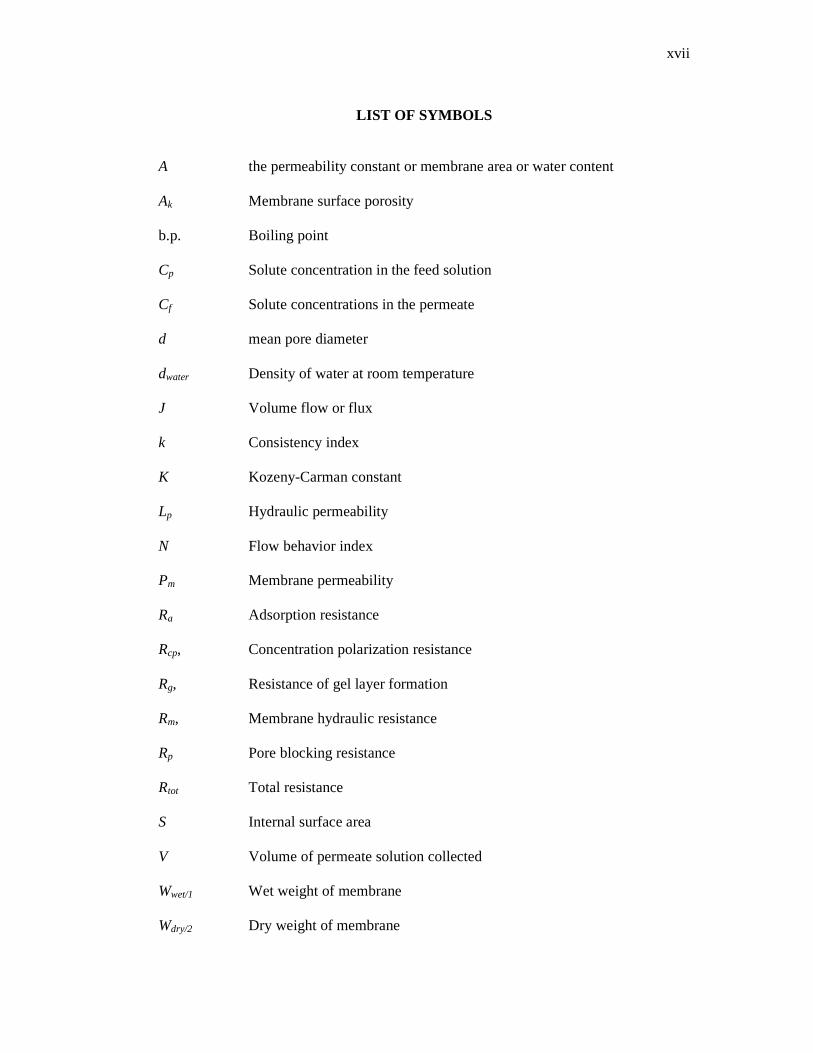
A the permeability constant or membrane area or water content Ak Membrane surface porosity b.p. Boiling point Cp Solute concentration in the feed solution Cf Solute concentrations in the permeate d mean pore diameter dwater Density of water at room temperature J Volume flow or flux k Consistency index K Kozeny-Carman constant Lp Hydraulic permeability N Flow behavior index Pm Membrane permeability Ra Adsorption resistance Rcp, Concentration polarization resistance Rg, Resistance of gel layer formation Rm, Membrane hydraulic resistance Rp Pore blocking resistance Rtot Total resistance S Internal surface area V Volume of permeate solution collected Wwet/1 Wet weight of membrane Wdry/2 Dry weight of membrane
xviii
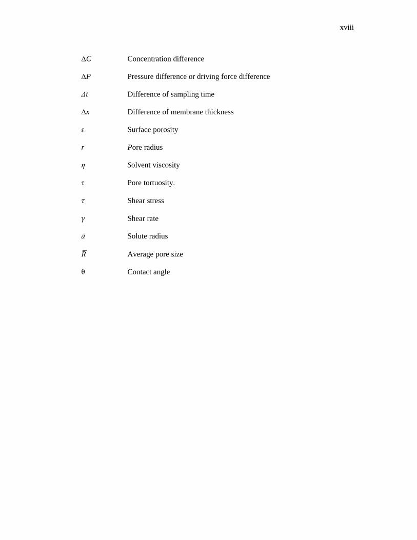
�C Concentration difference �P Pressure difference or driving force difference ∆t Difference of sampling time �x Difference of membrane thickness ɛ Surface porosity r Pore radius η Solvent viscosity τ Pore tortuosity. � Shear stress � Shear rate ā Solute radius � � Average pore size θ Contact angle

xix
LIST OF ABBREVIATIONS
AFM Atomic force microscope Al2O3 Alumina ATR-FTIR Fourier transform attenuated total reflection BSA Bovine serum albumin CA Cellulose acetate CAB Cellulose acetate butyrate CAP Cellulose acetate phthalate/cellulose acetate propionate CH4 Methane CMCA Carboxymethyl cellulose acetate CN Cellulose nitrate CO2 Carbon dioxide
CP Cellulose propionate CPSU Carboxylated polysulfone DER Dope extrusion rate DMFC Direct methanol fuel cell EA Egg albumin EC Ethyl cellulose ED Electrodialisis EPES Epoxy functionalized poly(ether-sulfone) GS Gas separation KH2PO4 Pottasium dihydrogen phosphate K2HPO4 di-Pottasium hydrogen phosphate MF Microfiltration

xx
MPC 2-methacryloyloxyethyl phosphorylcholine polymer MWCO Molecular weight cut-off N2 Nitrogen NF Nanofiltration NMP N-methyl pyrrolidone O2 Oxygen PA Polyamide PAA Polyarcrylic acid PAI Poly(amide-imide) PAN Polyacrylonitrilic/polyacronitrile PC Polycarbonate PE Polyethylene PEEK Poly(ether ether ketone) PEG Polyethylene glycol PEMFC Electrolyte membrane fuel cell PES Polyethersulfone PESA Poly(ether sulfonamide) PFSA Perfluorosulfonic acid PI Polyimide PMMA Poly(methyl methacrylate) PP Polypropylene PS Polyphenylene sulfide PS/PSf/ PSF/PSU Polysulfone PSO Polyphenylene oxide
xxi
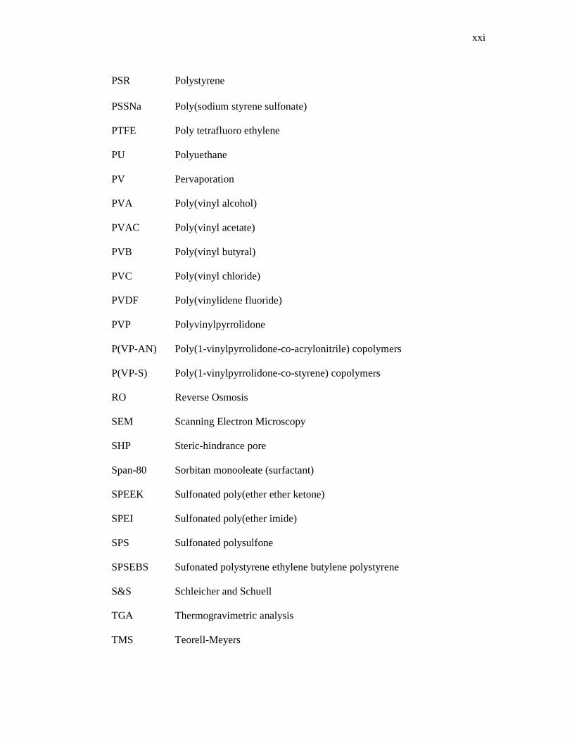
PSR Polystyrene PSSNa Poly(sodium styrene sulfonate) PTFE Poly tetrafluoro ethylene PU Polyuethane PV Pervaporation PVA Poly(vinyl alcohol) PVAC Poly(vinyl acetate) PVB Poly(vinyl butyral) PVC Poly(vinyl chloride) PVDF Poly(vinylidene fluoride) PVP Polyvinylpyrrolidone P(VP-AN) Poly(1-vinylpyrrolidone-co-acrylonitrile) copolymers P(VP-S) Poly(1-vinylpyrrolidone-co-styrene) copolymers RO Reverse Osmosis SEM Scanning Electron Microscopy SHP Steric-hindrance pore Span-80 Sorbitan monooleate (surfactant) SPEEK Sulfonated poly(ether ether ketone) SPEI Sulfonated poly(ether imide) SPS Sulfonated polysulfone SPSEBS Sufonated polystyrene ethylene butylene polystyrene S&S Schleicher and Schuell TGA Thermogravimetric analysis TMS Teorell-Meyers
xxii
UCLA University of California, Los Angeles UF Ultrafiltration ZrO2 Zircornia
CHAPTER 1
INTRODUCTION
1.1 OVERVIEW
Filter medium is the most important component of any filtration process. Filter
medium is permeable to one or more components of a mixture, solution, or suspension,
and is impermeable to the retaining component. The permeable component (permeate or
filtrate) is normally consists of suspending fluid or solvents or the mixture solvent and
other components. While, solid, or colloidal material, or molecular, or ionic species in
solution is the retaining component (retentate) at the surface side of the filter medium in
filtration process (Cheryan, 1998: Mulder, 1996 and Sutherland, 2005).
Filters media are manufactured using several methods and variety materials such
as natural fibers, synthetic fibers, synthetic sheet materials, and/or inorganic materials.
The common materials used in the fabrication of this filter media include cotton,
polymers, fiberglass, asbestos, sintered metals, carbon, ceramic, and natural minerals
(Sutherland, 2005). The filters can be classified into two categories: depth filter or
screen filter. In depth filtration, the component to be separated can be filtered on its
upstream surface or be penetrated through the surface pore and moves along the pore,
and then trapped within the thickness of the filter medium due to size exclusion or
adhered on the filter medium wall.

2
The screen filter operates in the same manner with a sieve where the separated
component retains on the upstream of a surface medium. Thus, membrane is generally
categorized as a screen filter since its separation technique is similar to the screen filter
(Cheryan, 1998). Filtration is the physical-mechanical process to separate two or more
components from a fluid (gas or liquid) based primarily on size differences (Geankoplis,
2003). In view of conventional application, filtration process generally refers to the
separation of solid immiscible particles from liquid or gaseous stream. The suspended
solids in a fluid are separated in part or totally from fluid, by passage of the fluid
through a permeable barrier (a filter medium) (Sutherland, 2005 and Cheryan, 1998).
The particles larger than 5 to 10 µm and/or above are separated by conventional
filtration method.
Membrane separation processes are employed to separate particles or solutes
with size diameters lower than 5 to 10 µm in a fluid (Cheryan, 1998). Compare to the
conventional separation process, this membrane separation process is also refers to the
separation of a solute from fluid by diffusion of this solute from a liquid or gas through
a semi-permeable membrane barrier to another fluid. This is because the membrane
separation process is not only accomplished by using mechanical-physical forces but
also involved molecular or chemical forces and diffusion (Geankoplis, 2003).
The term of membranes is primarily used for separation, and membrane
processes are generally refers to separation processes. Hence, the core in the membrane
separation process is the membrane itself (M’Bareck et al., 2006). The primary role of a
membrane is to act as a selective barrier which it permits passage of certain components
and retain certain other components of a mixture in fluid. The membrane can be
considered as a permselective barrier or interphase between two phases and the ability
of the membrane to transport one component from feed mixture more readily than other
components is known as membrane separation process (Mulder, 1996).
3
The structure of a membrane is vital for the performance of the membrane.
There are two types of membrane structures, i.e. symmetric structure and asymmetric
structure. Membranes with symmetrical structure do not change throughout the cross
section of the membrane while asymmetric membrane consist of a thin selective layer
and a strong support layer giving mechanical strength. In term of membrane
productivity, asymmetric membranes are in general superior compared to symmetric
membranes (Rijn, 2004).
1.2 ASYMMETRIC MEMBRANE
In early 1960’s, Loeb and Sourirarajan made a novel discovery of reverse
osmosis process by developing an asymmetric cellulose acetate membrane via phase
inversion method with high permeation rate and high selectivity for desalination of
saline water. This is due to the unique structure of these types of membranes comprising
of a very thin, relatively dense skin layer supported by an open porous sub-layer. The
permeability and high selectivity of the membrane is imparted by the skin layer while
the mechanical strength is provided by the porous sub-layer. The fabricated asymmetric
membranes via phase inversion process can be tailored to the specific application in
order to produce the desired purity of permeate by manipulating some membrane
parameters condition during the membrane fabrication process applications (Baker,
2004 and Mulder, 1996).
The characteristics and morphological structure of a dense top layer and porous
sub-layer can be optimized by adjusting the membrane preparation conditions. The
optimization usually requires time consuming and extensive trial and error
experimentation. Nowadays, most asymmetric membranes are fabricated by phase
inversion, which can be achieved through five principal methods: vapor induced phase
separation, thermally induced phase separation, dry phase separation, wet phase
separation and dry wet phase separation (Hamzah et al., 2012; Nguyen et al., 2010;
Peng et al., 2012; Rajabzadeh et al., 2012, and Riyasudheen and Sujith, 2012)
4
In all these techniques, an initially homogeneous polymer solution
thermodynamically becomes unstable due to different external effects and phase
separates into polymer rich and polymer lean phases. The former forms the matrix of
the membrane and the latter fills the pores. The formation of a thin dense skin layer and
a porous sub-layer of a membrane is a typical structure of an asymmetric membrane
(Ismail et al., 2011)
1.3 MEMBRANE TECHNOLOGY
The invention of the asymmetric membranes by Loeb and Sourirajan has made a
great impact on the growth of membrane science and technology. Their breakthrough
has put a milestone in the history of membrane technology progress. This remarkable
finding has opened the door to commercialize the membrane technology from lab-scale
membrane application turn to large-scale commercial. Since that, membrane technology
has been found to be an alternative and attractive approach for separation. This
technology has been widely adopted by different industries over 50 years.
Large-scale commercial industries have been employed membrane separations
processes to displace conventional separation processes such as in the water treatment,
water purification, waste water treatment, pharmaceutical, biotechnology, chemicals and
paper industries as well as petrochemical-related industries. This is due to the
membrane separation processes are compact, faster, and more capital and energy
efficient compare to conventional separation methods (Anadao et al., 2010). Most of the
membrane technology applied in commercial industries employed pressure-driven
membrane separation processes. The membrane separation process based on pressure-
driven can be classified into four categories, i. e. microfiltration (MF), ultrafiltration
(UF), nanofiltration (NF) and reverse osmosis (RO).
MF membrane is designed to retain particles in the ‘micron’ range of about 0.10
to 5 µm while UF used to separate macromolecules or particles larger than about 0.001
to 0.02 µm (10 to 200 Å) (Cheryan, 1998). Both membranes can be considered as
porous membrane where rejection is determined mainly by the size and shape of solutes
relative to the membrane pore size. The transport of solvent is directly proportional to
5
the applied pressure (Mulder, 1996). Nanofiltration (NF) membrane is a membrane
filtration process using membrane with a pore size ranging from 1 to 10 nm (5 to 10 Å).
It lied between ultrafiltration and reverse osmosis. In general, NF membrane employed
to separate organic compounds and (multivalent) ions from a solvent (Baker, 2004 and
Schafer et al., 2005).
RO is mainly employed in the desalination of brackish and seawater to produce
portable water. It also applied to produce ultrapure water in an electronic industry. The
RO membrane shows different transport rates of molecules as small as 2 to 5 Å. The
separation principle of NF and RO are based on solution-diffusion mechanisms. Among
these membrane processes, ultrafiltration (UF) has the largest potential membrane
process employed in various industries application fields (Baker, 2004; Kubota et al.,
2008; Mulder, 1996 and M’Bareck et al., 2006). Ultrafiltration (UF) process uses a
finely porous membrane to filter and separate water and microsolutes from
macromolecules and colloids. The UF membrane has the average pore diameter in the
10 - 1000 Å range (Baker, 2004).
Nowadays, UF is a well-developed membrane separation technology and
recently, its application is growing up rapidly in a wide range of applications, including
water/wastewater treatment, reverse osmosis pretreatment, and separations in the food,
dairy, paper, textile, pharmaceuticals, chemical and biochemical industries (Celik et al.,
2011 and Guo et al., 2010). It is also one of the promising separation tools in drinking
water and wastewater reuse because of its effectiveness to remove waterborne
pathogens (such as bacteria, viruses, and protozoa cysts). In this respect, particulate
matter and small pore size provide an absolute barrier to particles, bacteria, high
molecular weight organic molecules, emulsified oils and colloids (Adout et al., 2010;
Shen et al., 2011 and Shong et al., 2011).
Some of the major profits of the application of the UF membrane process
include low energy cost; the ability to operate near ambient conditions; ease of use and
the quality of permeate produced. As a consequence of this, increasing demand efforts
to improve UF process performance are gaining more and more attention. In general,
those efforts are focusing mainly on feed pretreatment, advanced membrane module

6
design and process condition optimization. However, in many cases, the membrane
itself is the main key material for the performance of the UF process and most of the
commercial polymeric UF membranes are prepared by phase inversion technique (Teli
et al., 2012).
Phase inversion technique is a common technique and a well-known method in
producing asymmetric UF membranes in nowadays. The main important component in
membrane preparation via phase inversion process is the polymeric materials, which
determine the characteristics and properties of the produced membranes. Some of these
polymeric materials such as cellulosic’s (e.g. cellulose acetate, cellulose nitrate),
polyacrylonitrile (and related block-copolymers), polysulfone/polyetehersulfone/
sulfonated polysulfone/sulfonated poly(ether-ethersulfone), polyvinylidene flouride,
polyimide/poly ether imide, aliphatic polyamides, polyetherketone and ulfonated
poly(ether–ether-ketone) are used as a back-bone of ultrafiltration membrane (Mulder,
1996 and Nady et al., 2011). The selection of polymer material as a polymer back-bone
to prepare an UF membrane via phase inversion process is very crucial due to the
physical, chemical and mechanical properties of this membrane is strongly related to the
selected polymer and this in turn affects the separation performance of the respective
UF membrane.
1.4 PROBLEM STATEMENT
Cellulose acetate (CA) and polysulfone (PSf) are the most common polymers
employed as polymer back-bone in the fabrication of commercial UF membranes. These
polymers are selected due to their fairly important characteristics for UF applications
(Cho, et al., 2011). CA is the classic membrane materials and still being successfully
used especially in water treatment. The membrane fabricated from this polymer is
relatively easy to manufacture and low manufacturing cost. Another several advantages,
CA membrane posses a good fouling resistance, a more stable performance, high flux,
and has moderate chlorine resistance. However, the disadvantages of CA membranes
are poor mechanical strength, less stable in organic solvents, narrow pH range (pH 3-7),
a narrow temperature range (lower than 50 oC) and less resistance to biological attack
(Cheryan, 1998; Nunes and Peinemann, 2006, and Zavastin, et al, 2010)
7
PSf is an attractive and important class polymer which is more stable and high
performance in harsh operating conditions compare to CA membrane. It has been most
widely used in the manufacture of synthetic asymmetric UF membranes. Besides it used
as a basic material for synthetic UF membranes, this polymer also used as support
material for composite membrane (Mulder, 1996). PSf membrane has been employed
in various application in UF processes due to it poses an excellent mechanical property,
a very good chemical and thermal stability as well as its high rigidity and creep
resistance (Arthanareeswaran et al., 2007a; Bowen et al., 2001; Mulder, 1996, and
Rahimpour and Madaeni, 2007)
However, the main disadvantages of PSf membrane are due to its hydrophobic
characteristic. The hydrophobicity of polysulfone membrane has restricted the
application of the commercial PSf membranes in various aqueous applications. This is
due to the nature of the membrane surface leads to an easy deposition of hydrophobic
macromolecular solutes or particles (such as in protein filtration) on/at the membrane
surface. This phenomenon is known as membrane fouling. In this circumstance, the
larger pressure is required to induce the solvent transport through the membrane to
increase water flux through membrane pore due to increase in the membrane surface
resistance (Blanco et al., 2006).
In practical application of UF systems, membrane fouling is a serious problem.
In the drinking water production, even though UF is a very promising process due to its
compactness, easy automation and high performance but the main obstacle for wider
application of UF in this industry is the membrane fouling. Pore blocking, pore stricting
and cake formation are the major factors that contributed to the membrane fouling and
these factors usually cause high cost energy, operation, and maintenance (Gao et al.,
2011).
Therefore nowadays, many research groups have focused on enhancing property
and anti-fouling capability of PSf membrane in order to prolong the lifetime and
therefore widen the application of PSf membranes (Zhang et al., 2011). It is well-known
and generally accepted among membranologist that increasing the hydrophilicity of
membrane will improve antifouling of the membrane. It is also recognized that

8
modification of hydrophobicity of polysulfones membrane is helpful to reduce
membrane fouling and prevent the flux-decreasing (Yi et al., 2010). Recently, many
membranologist has attempted to improve the hydrophilicity of hydrophobic UF
membrane via several methods such as surface modification, plasma treatment, grafting
and blending (Rahimpour et al., 2008)
Polymer blend is a simple and efficient method for designing new materials to
improve performance of the hydrophobic membranes. Polymer blend is a process, in
which two organic polymers are blend in a homogeneous membrane casting solution,
which generally contains a solvent or/and an additive. The polymer blend is a proven
tool to obtain new types of UF membrane, which has better hydrophilicity compared to
the original membranes (Sivakumar et al., 2006 and Bowen et al., 2001). The
hydrophilization of hydrophobic UF membrane materials will improve permeability and
permselectivity of membrane towards producing of a high performance of UF blend
membranes. Recently, many researchers had reported their study on blending of
hydrophobic membranes with hydrophilic polymers.
Cellulose acetate phthalate (CAP) is one of the potential hydrophilic organic
polymers that can be used and explored in PSf polymer blend technique. CAP has a
superior characteristics compared to cellulose due to the presence of numerous acidic
and carbonyl functional groups on its structure and was added to PSf casting solutions
to improve hydrophilicity and performance of PSf membranes. Rahimpour and Madaeni
(2007) claimed that CAP plays a role as a remarkable antifouling agent due to addition
of small amount of CAP in polyethersulfone (PES) membrane casting solution
significantly improved the performance and antifouling property of PES membrane.
Even though, PES has similar chemical and thermal limits to PSf, however, its
performance when in contact with the process fluids can be markedly different (Scott
and Hughes, 1996). In view of this, an attempt has been made to investigate the effect of
using different composition of CAP in casting solution in terms of hydrophilicity
properties, morphology and performance of PSf based membranes.
9
The production of asymmetric UF membrane is not only influenced by polymers
used but three other components, which are solvent, non-solvent and additive, and these
factors have significant effects on membrane characteristics. The presence of additive in
membrane casting solutions plays a crucial role in adjusting the membrane properties.
Generally, additives create spongy membrane structure by preventing the macrovoids
formation, enhance pore formation, improve pore interconnectivity and introduce
hydrophilicity (Rahimpour et al., 2007 and Liu et al., 2003). Usually, a hydrophilic
additive such as polyvinylpyrrolidone (PVP) or polyethylene glycol (PEG) is mixed in
casting solution to obtain hydrophilic membrane (Rahimpour et al., 2008). These
additives were employed in polymer blend membranes in order to improve
hydrophilicity and performance of the blend membranes. Investigation on the
rheological factors (such as shear rate) and the effect of convective evaporation time
(dry phase) during membranes fabrication process provides a potential platform for
developing high performance membrane. It is believed that these two factors play an
important role in the membrane fabrication process by altering molecular orientation
during formation of the high performance membranes.
In this study PSf is considered as the main polymer for PSf/CAP blend UF
membranes. The effects of different polymers composition of PSf/CAP blend were
studied in terms of membrane morphology, pore properties, hydrophilicities properties
and performance of PSf/CAP blend membranes. The results of the PSf/CAP blend
membranes were compared to the original membrane, PSf membrane. Then, the best
PSf/CAP blend membrane was selected to study the role of an organic additive, PVP in
the blend membrane. PSf/CAP/PVP blend membranes were prepared by varying the
concentrations of PVP in the best PSf/CAP blend membrane. The effects of PVP were
studied to find the best PSf/CAP/PVP blend membrane performance.
Next, two membrane fabrication condition parameters (shear rate and
evaporation time) were used to produce PSf/CAP/PVP blend membrane with high
rejection performance. First, the best PSf/CAP/PVP blend membranes were cast at
different shear rate and then, the best blend membrane was determined based on protein
separation performance test. Finally, the PSf/CAP/PVP blend membranes were
fabricated at different evaporation time at the best shear rate condition. It were tested to

10
find the best high performance of PSf/CAP/PVP blend membrane in terms of high
permeate flux and high rejection of protein solution at the best membrane fabrication
condition parameters (shear rate and evaporation time).
1.5 OBJECTIVES
The objectives of this study are as follows:
i. To study the effects of CAP in PSf/CAP blend membranes on hydrophilicity
properties, pore properties, morphological structures and performance of
PSf/CAP blend membranes.
ii. To investigate the role of organic additive, PVP in improving the membrane
properties and performance of PSf/CAP/PVP blend membranes.
iii. To study the effects of fabrication condition, i.e. shear rate during membrane
fabrication on the characteristics, performance and morphology of
PSf/CAP/PVP blend UF membranes.
iv. To investigate the influence of convective evaporation time (dry phase) on
PSf/CAP/PVP blend membranes in order to find the best preparation
condition for high performance membrane.
v. To determine the best dope formulation and the best fabrication condition of
dry/wet phase inversion process for producing high performance asymmetric
PSf/CAP/PVP blend ultrafiltration membranes.
1.6 SCOPES
In order to achieve the above mentioned objectives, the following scopes of
works have been drawn:
i. Preparing PSf dope solution and PSf/CAP blend dope solutions which
containing different polymer composition of PSf/CAP.
ii. Fabricating PSf and PSf/CAP blend UF membranes via wet-phase inversion
technique by using an electrically-automatic casting machine.
iii. Characterizing PSf and PSf/CAP blend UF membranes in terms of water
content, contact angle, pore characteristics and morphology.

11
iv. Determining the best PSf/CAP blend UF membrane in terms of pure water
permeation and performance test of proteins.
v. Preparing and fabricating PSf/CAP/PVP blend UF membranes containing
different concentrations of PVP additive.
vi. Characterizing PSf/CAP/PVP blend UF membranes and determining the best
PSf/CAP/PVP blend UF membrane.
vii. Preparing the blend UF membrane by varying fabrication process parameters
such shear rate and evaporation time.
viii. Determining the best fabrication process parameters in order to produce the
best PSf/CAP/PVP blend UF membrane performance.
1.7 OVERVIEW OF THE THESIS
This thesis is organized in five chapters including introductory chapter in
Chapter 1, literature review in Chapter 2, materials and methodology in Chapter 3,
Chapter 4 about results and discussion and finally, conclusion and recommendations in
Chapter 5. Firstly in Chapter1, the information about filter media and types of filtration
is briefly discussed. Then, the difference between a conventional separation and
membrane separation process is explained. The information about asymmetric
membranes and membrane technology processes are also described. The problem
statement, objectives and scope of study in preparing PSf/CAP and PSf/CAP/PVP blend
membranes are included in this chapter.
Chapter 2 covers detail explanations about membrane and membrane separation
processes. A historical literature about chronological development of ultrafiltration (UF)
membranes and UF membrane materials are covered. Background on formation of
asymmetric UF membranes via dry phase, wet phase and dry/wet phase method well
explained. The fundamental knowledge and theories about transport mechanisms in UF
membranes are also explained. The role of materials, additive, shear rate and
evaporation time effects on membrane structures properties and separation performance
is discussed. This chapter also described about characterization of UF membranes in
terms of water content, contact angle, MWCO and pore properties as well as SEM.
Explanations about membrane fouling was also included.

12
Materials and methodology of this study were described in Chapter 3. In this
chapter, all the materials employed in this study such as PSf, CAP, NMP, PVP and
proteins are discussed. The details about the preparation of PSf/CAP and PSf/CAP/PVP
membrane casting solutions and membrane fabrication system are well explained.
Chapter 3 also describes the details of membrane characterizations and membrane
performance tests. There are two types of membrane separation performance tests, i.e.
pure water permeation test and protein separation test.
All the characterization and performance test results of PSf/CAP and
PSf/CAP/PVP blend membranes are discussed in detail in Chapter 4. In this chapter, the
effects of CAP and PVP on PSf/CAP/PVP blend membranes are explained in terms of
water content, contact angle, membrane permeability and porosity. The membrane
surface properties are also described in term of MWCO, average pore size and pore
density. Pure water flux, proteins rejection and proteins permeate flux are used to study
the membrane performance. SEM photographs are used to support the explanation
about membrane performance. The best membrane performance is determined based on
the membrane characteristics and membrane separation performance. The effects of
shear rate and evaporation time on PSf/CAP/PVP blend membranes are also well
discussed in this chapter.
Finally, Chapter 5 deals with the conclusion and recommendations. This chapter
presents the conclusion derived from this research study. Recommendations for future
study in order to improve fundamental knowledge about PSf/CAP/PVP membrane
blends and to enhance separation performance are discussed. The raw experimental data
and sample calculations are presented in the Appendices.
CHAPTER 2
LITERATURE REVIEW
2.1 MEMBRANE
Over the last 50 years, membrane separation technology is in a state of rapid
growth and innovation. Membrane science and technology is an expanding field and has
become a prominent part of many activities within the process industries. Industrial
membrane separation with synthetic membranes has been strongly developed since the
introduction of asymmetric polymeric membranes in the early sixties.
Membrane science and technology is interdisciplinary fields which involved
chemist, physical chemist, mathematicians and chemical engineers. The role of chemists
is to develop new membrane structures, while physical chemists and mathematicians
take part to describe the transport properties of different membranes using mathematical
models in order to predict membranes separation characteristics. Meanwhile, chemical
engineers contribute in designing separation processes for large scale industrial
utilization (Strathmann, 1990).
However, the most important element in membrane science and technology is
the membrane itself. The membrane is the heart of every membrane processes (Scott
and Hughes, 1996). There are a number of definitions of the word “membrane” and it is
difficult to covers all of its aspects and roles. A membrane can often be better described
in terms of what it does rather than what it is. Prof. George Solt, a former Director of
the School of Water Sciences, Cranfield has defined a membrane as “a material through
which one type of substance can pass more readily than others, thus presenting the basis

14
of a separation process” (Judd and Jefferson, 2003). For the purpose of this research,
Solt’s definition can be considered adequate to describe what the membrane itself is.
Membranes can be classified according to different viewpoints but generally it can
be divided into four categories as below (Cheryan, 1998 and Mulder, 1996):
a) Nature of the membrane – natural (biological) or synthetic membranes
b) Structure or morphology of the membrane – porous versus nonporous
membranes, its morphological characteristics, or as liquid membranes
c) Applications of the membrane – gaseous phase separation, gas-liquid, liquid-
liquid, etc.
d) Mechanisms of membrane action – adsorptive versus diffusive, ion-exchange,
osmotic, or nonselective (inert) membranes
2.2 MEMBRANE SEPARATION PROCESSES
Membrane technology is now well accepted as a cost-effective technology and
conferring unique advantages over conventional separation processes. The driving
expansion in environmental applications due to the improvements of the underlying
technology, a more competitive market, a more stringent regulatory environment,
broader range of membrane processes offered and the availability of new fabrication
materials make membrane processes as the best available alternative separation
technologies. Membrane technology plays an increasingly important role as unit
operations for resource recovery, pollution prevention, energy production,
environmental monitoring and quality control, fuel cells and bio-separation applications.
Most of the membrane separation processes are pressure-driven. In pressure-
driven membrane separation process, separation is achieved due to a driving force, i.e.
pressure, acting on the components in the feed and this driving force has induced one
component to transport through the membrane readily than any other components in the
feed. The major pressure-driven membrane separation processes which cover a wide
range of particles or molecular sizes, and applications are microfiltration (MF),
ultrafiltration (UF), nanofiltration (NF), reverse osmosis (RO) (Cheryan, 1998). Table

15
2.1 shows a classification of various membrane separation process based on particle or
molecular size, driving force and transport mode. Characteristics of retentate and
permeate in different membrane processes is presented in Table 2.2.
Table 2.1: Characteristics of membranes used in different membrane
separation processes
Process Structure Pore size
(µm)
Driving force,
bar
Transport
mode
MF UF NF RO Dialysis PV ED Gas Separation (GS)
Symmetric, asymmetric Asymmetric Thin film asymmetric Thin film asymmetric Symmetric, asymmetric Asymmteric, homogeneous Cations and anions exchange Asymmetric, composite, homogeneous
0.05 to 10.0 0.001 to 0.1 < 0.002 < 0.002 0.001 to 0.1 nonporous nonporous nonporous (or porous < 1.0 µm)
Pressure, (�P) 0 to 1 Pressure, (�P) 1 to 10 Pressure, (�P) 10 to 25 Pressure, (�P) 10 to 100 Concentration (∆C) Partial pressure Electrical potential (current/voltage) Pressure, (�P) 10 to 100
Sieving Sieving Solution diffusion Solution diffusion Sieving + diffusivity Solution diffusion Ion migration Solution diffusion
Source: Baker (2004), Porter (1990), Scott (1995) and Mulder (1996)

16
Table 2.2: Characteristics of retentate and permeate in different membrane processes
Process Retentate Permeate
MF
UF
NF
RO
Dialysis
PVP
ED
Suspended particles, water
Large molecules, water
Small molecules, divalent salts,
dissociated acids, water
Solute, water
Large molecules, water
Non-volatile molecules, water
Non-ionic solutes, water
Dissolved solutes, water
Small molecules, water
Monovalent ions, undissociated
acids, water
Water
Small molecules, water
Volatile small molecules, water
Ionized solutes, water
Source: Cheryan (1998)
MF is widely used for the separation, purification and clarification of protein-
containing solutions including the recovery of extracellular proteins produced via
fermentation and for the removal of bacteria and viruses in the final formulation of
therapeutic proteins. In all these processes the macromolecules and proteins involved
are much smaller in size than the pores of the MF membrane and should not normally
be retained by the membranes (Kelly and Zydney, 1995). The basic operational concept
of MF leads to a solute concentration that is higher and close to the membrane surface
than it is in the bulk feed stream (Wakeman and Williams, 2002). Module configuration
of MF include hollow-fiber, tubular, flat plate, spiral-wound and rotating devices. The
two standard modes of operation are dead-end and cross-flow configurations.
UF membranes process is between MF and NF membranes. The UF membranes
were discussed in the next sub-chapter. NF membrane has two extraordinary characters.
First, they have intermediate molecular weight cutoff between pure RO with a salt
rejection higher than 90 %, and pure UF with a salt rejection of less than 5%. The
MWCO of NF membranes ranged from 0.2 to 10 kDa; the pore diameters estimated
from the Stokes-Einstein relationship range from 1 nm to a few nm (Wang, et al., 1995).
NF membranes pore sizes are in the ionic and molecular range, multivalent ions and

17
larger organic molecules are well rejected, while monovalent ions are unsuccessfully
rejected. In NF membrane, solutes having sizes larger than the pore size of membranes
cannot pass through the membrane and retained on the membrane surface (Mohammad,
1998).
Reverse osmosis membrane acts as a barrier to flow, allowing selective passage
of a particular species (solvent) while other species (solutes) are retained partially or
completely. Solute separation and permeate solvent (water in most cases) flux depend
on the material selection, the preparation procedures, and the structure of the membrane
barrier layer (Lloyd, 1985, and Sourirajan and Matsuura, 1985). Cellulose acetate (CA)
is the material for the first generation reverse osmosis membrane. Utilization of this
kind of membrane for sea water desalination triggered the applications of membrane
separation processes in many industrial sectors. The great interest of reverse osmosis is
a high-quality of permeate, and often even too good. The limitation of this membrane is
operated at high operating pressure resulted in a considerable high energy cost.
2.3 CHRONOLOGICAL OF ULTRAFILTRATION DEVELOPMENT
The beginnings of ultrafiltration (UF) are coincident with reverse osmosis (RO)
around 1960s. In 1906, Benchhold produced collodion (nitro cellulose) membranes with
pore sizes below 0.01 micron. This is the first synthetic ultrafiltration membrane that
has been fabricated and developed. He also introduced the term ‘ultrafilter’ to these
collodion membranes. The collodion membranes produced by Benchhold were low in
the hydraulic permeability and its pores were easily plugged (Baker, 2004 and Porter,
1990).
Other important early workers were Zsigmondy and Bachmann, and Ferry and
Elford. Zsigmondy and Bachmann patented their collodian filter in 1918 (Baker, 2004).
After a few stages of evolution and innovation in producing collodion membranes,
collodion ultrafiltration and microfiltration membranes were widely used in laboratory
studies by the mid-1920s. Before 1960s, although RO and UF membranes showing
promising results in their retention properties but there were no application of RO or UF
18
processes in any industry. It is due to the both membranes had impractical filtration
rates (flux) (Cheryan, 1998 and Porter, 1990).
At the end of World War II, the United States (U.S.) Government became
concerned about shortages in water before the end of the century and with the proactive
action, the U.S. Government has funded substantial financial resources for the
development of various separation processes in water desalination for over two decades
(1950-1973). In the mid-1950s, Prof Charles E. Reid from the University of Florida and
Sourirajan from University of California, Los Angeles (UCLA) has started the first
work in RO by using cellulose acetate (CA) as a semi-permeable medium towards
seawater electrolytes. They found that the salt rejection of 94% but the water fluxes
were too low to be interesting (Porter, 1990).
In 1959, Sourirajan’s partner, Sidney Loeb uncovered CA membrane recipe
introduced by a French investigator, Dobry and he introduced acetone into Dobry’s
recipe as suggested by Llyod Graham, a UCLA graduate student. He found a
remarkable results after annealed CA membrane at 80 oC to yield a salt rejection of 99%
and the water flux was 200 times greater than Sorirajan’s CA films and 5 times greater
than the annealed Schleicher and Schuell (S&S) membrane (Schafer et al., 2005). This
finding was a very promising result and consequently made a crucial breakthrough in
producing RO and UF asymmetric or anisotropic membranes in a large fabrication scale
especially for industrial applications.
The major reason for this significant breakthrough resided in the asymmetric
structure of the membrane. Loeb has found there were two layers exists in the
asymmetric membrane, a dense skin layer which less than 1 µm in thickness and a
porous layer below the dense layer. The dense skin layer or thin layer is responsible to
the rejection of solutes and at the same time it minimized the hydraulic permeability of
water/solvent through the membrane. The porous layer provided mechanical strength of
the asymmetric membrane at high operating pressure (Mulder, 1996 and Porter, 1990).

19
Prof. Alan S. Michaels from Massachusetts Institute of Technology and the
founder of Amicon Corporation took initiative to make collaboration between Amicon
and Dorr-Oliver in a joint development program to develop UF membranes. In 1966,
they were succeeded in producing asymmetric UF membranes from many polymers
such as polyacrylonitrile copolymers, aromatic polyamides, polysulfone and
poly(vinylidene fluoride). The ten-year period between 1965 and 1975 was a period of
intense development of chemically and thermally resistant UF membranes which were
fabricated from the above mentioned polymers and today, these materials are still
widely used in ultrafiltration membrane making (Baker, 2004 and Porter, 1990).
Hollow fibers were also developed during this decade and followed later by
tubes, plate and frame unit, and spiral wound modules became available. First
commercially significant ceramic membrane was introduced in 1988. Even though
ceramic membranes much more expensive than polymeric membrane but ceramic
membranes can be employed in high temperature operating condition or require regular
cleaning with harsh solutions to control membrane fouling (Baker, 2004). Some of the
milestones in the development of ultrafiltration membranes are summarized in Table
2.3.
2.4 ULTRAFILTRATION MEMBRANES
Currently, reverse osmosis (RO) and ultrafiltration (UF) are the two most
important membrane separation processes in the wide range of industrial applications.
The success of these membrane processes is due to a great extent in development of
asymmetric membranes. Asymmetric membranes can be regarded as a dual-zone
system, consisting of very thin active layer (skin) and a much thicker, porous support
layer (Rautenbach and Albrecht, 1989). The schematic diagram of an asymmetric
membrane consists of two layers is shown in Figure 2.1.
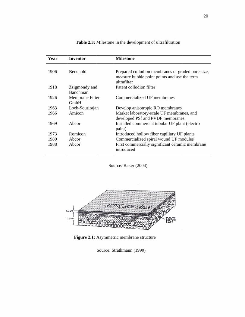
Table 2.3: Milestone in the development of ultrafiltration
Year Inventor
1906 1918 1926 1963 1966 1969 1973 1980 1988
Benchold Zsigmondy and Banchman Membrane Filter GmbH Loeb-SourirajanAmicon Abcor Romicon Abcor Abcor
Figure 2.1: Asymmetric membrane structure
Milestone in the development of ultrafiltration
Inventor Milestone
Zsigmondy and
Membrane Filter
Sourirajan
Prepared collodion membranes of graded pore size, measure bubble point points and use the term ultrafilter Patent collodion filter Commercialized UF membranes Develop anisotropic RO membranes Market laboratory-scale UF membranes, and developed PSf and PVDF membranesInstalled commercial tubular UF plant (electro paint) Introduced hollow fiber capillary UF plantsCommercialized spiral wound UF modulFirst commercially significant ceramic membrane introduced
Source: Baker (2004)
Asymmetric membrane structure
Source: Strathmann (1990)
20
Prepared collodion membranes of graded pore size, measure bubble point points and use the term
scale UF membranes, and
developed PSf and PVDF membranes Installed commercial tubular UF plant (electro
hollow fiber capillary UF plants Commercialized spiral wound UF modules First commercially significant ceramic membrane

21
The active layer on the top of the asymmetric membranes is the prominent
feature of these membranes and generally, it thickness is around about 0.1 to 1.0 µm.
This thin skin permits high hydraulic permeability of the permeate. The second layer or
also known as a support layer is more open or porous substructure (typically 100 to 200
µm in thickness) provides good mechanical support to asymmetric membranes. High
mass transfer rates and good mechanical stability are the unique properties offered by
these two layers of asymmetric membranes that has been widely used in RO, UF or gas
separation processes (Porter, 1990 and Scott and Hughes, 1996).
Asymmetric membrane separation performance can be determined by the nature
of the skin polymer, membrane pore size and the mass transport rate, which mainly
governed by the skin thickness. Furthermore, the thickness, porosity and pore size of the
dense skin control permeability and selectivity of asymmetric membranes at a given
operating pressure and temperature. The highly porous sub-layer reacts as a support
layer for the fragile and thin skin as well as provides the mechanical strength or
stability. This highly porous sub-layer allows the membrane to tolerate the pressure
effects employed during membrane operations.
Ultrafiltration (UF) membranes typically refer to anisotropic (asymmetric)
membranes with porous surface layer which have pore diameter from 10 to 1000 Å. UF
membranes covers the region between MF and NF. The finely porous surface layer (also
known as a skin layer or a top dense layer or a thin active layer or a very thin selective
skin layer) performs separation of dissolved macromolecules by discriminating them by
their sizes via sieve mechanism (Baker, 2004). In the sieve mechanism, the separation
of the dissolved macromolecules is determined by the size and shape of the solutes
relative to the pore size in the UF membranes (Mulder, 1996). In industrial
applications, UF membranes are used to remove particles in the size range of 0.001 to
0.02 µm as retained materials, whilst solvents and salts of low molecular weight will
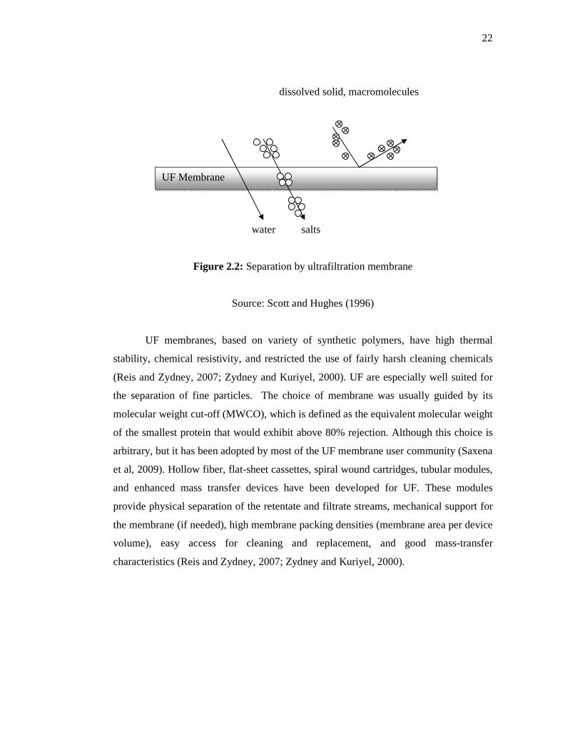
pass through the UF membranes as depicted in Figure 2.2.
22
Figure 2.2: Separation by ultrafiltration membrane
Source: Scott and Hughes (1996)
UF membranes, based on variety of synthetic polymers, have high thermal
stability, chemical resistivity, and restricted the use of fairly harsh cleaning chemicals
(Reis and Zydney, 2007; Zydney and Kuriyel, 2000). UF are especially well suited for
the separation of fine particles. The choice of membrane was usually guided by its
molecular weight cut-off (MWCO), which is defined as the equivalent molecular weight
of the smallest protein that would exhibit above 80% rejection. Although this choice is
arbitrary, but it has been adopted by most of the UF membrane user community (Saxena
et al, 2009). Hollow fiber, flat-sheet cassettes, spiral wound cartridges, tubular modules,
and enhanced mass transfer devices have been developed for UF. These modules
provide physical separation of the retentate and filtrate streams, mechanical support for
the membrane (if needed), high membrane packing densities (membrane area per device
volume), easy access for cleaning and replacement, and good mass-transfer
characteristics (Reis and Zydney, 2007; Zydney and Kuriyel, 2000).
UF Membrane
water salts
dissolved solid, macromolecules

23
2.4.1 Materials of Ultrafiltration Membranes
Ultrafiltration (UF) membranes can be categorized according to the material
composition which is either organic (polymeric) or inorganic (ceramic or metallic).
Polymeric UF membranes such as polysulfone/polyetehersulfone/sulfonated
polysulfone, polyvinylidene flouride, polyacrylonitrile (and related block-copolymers),
cellulosics (e.g. cellulose acetate), poly(phenylene sulfide) and polyimide/ poly(ether
imide) are prepared by phase inversion process and commercially used in these days in
various applications (Mulder, 1996 and Nunes and Peinemann, 2006). Synthetic
polymeric membranes can also be divided into hydrophobic and hydrophilic
classifications. Table 2.4 shows the various hydrophilic and hydrophobic polymers used
for membrane production.
Table 2.4: Commercial available hydrophilic and hydrophobic polymers for membrane production
Hydrophilic polymers Hydrophobic polymers
Cellulose acetate (CA)
Cellulose acetate butyrate (CAB)
Cellulose acetate propionate (CAP)
Cellulose nitrate (CN)
Cellulose propionate (CP)
Ethyl cellulose (EC)
Polyamide (PA)
Poly(acryl acid) (PAA)
Poly(vinyl alcohol) (PVA)
Poly(vinyl acetate) (PVAC)
Poly(vinyl butyral) (PVB)
Polysulfone (PSf)
Polyethersulfone (PES)
Poly(vinyidenel flouride) (PVDF)
Polycarbonate (PC)
Polypropylene (PP)
Poly(methyl methacrylate) (PMMA)
Poly tetrafluoro ethylene (PTFE)
Polyethylene (PE)
Polystyrene (PS)
Polyphenylene oxide (PSO)
Polyphenylene sulfide (PS)
Source: Kesting (1985), Lloyd (1985) and Mulder (1996)

24
Alumina (Al2O3) and zircornia (ZrO2) have been used as inorganic materials for
developing ceramic UF membranes. These ceramic UF membranes were employed to
replace polymeric UF membranes especially for harsh operating condition such as high
operating temperature and various pH range (Mulder, 1996). Although membrane
materials vary vastly according to chemical compositions, the principal objectives in
manufacturing of commercial membranes are to produce membrane with high
selectivity, high flux and less fouling as well as highly resistant to chemical and heat.
The common commercial available polymeric membranes for MF, UF, NF and RO
membranes in water industries with their advantages and disadvantages are
demonstrated in Table 2.5.
Table 2.5: Advantages and disadvantages of phase inversion polymeric membranes in water industries
Polymera Advantages Disadvantages Processb
CA PA PAN PSf, PES PVDF, PTFE PEI PP
Chlorine resistant Inexpensive More fouling resistance than PA More all-around stability than CA High resistance to hydrolisis High resistance to oxidation Very good all-round stability Mechanically strong Extremely high chemical stability High thermal stability High chemical stability Very high thermal stability Mechanically strong Inexpensive
Susceptible to alkaline hydrolisis at pH > 6 Susceptible to biodegradation Limited thermal and chemical stability Very limited chlorine tolerance (<0.1 ppm) Hydrophobic Requires copolymers to make less brittle Hydrophobic Highly hydrophobic Limited intrinsic permeability Expensive Hydrophobic Less solvent resistant than PVDF Poorer alkaline stability than PSf or PAN Hydrophobic
UF, NF, RO NF, RO UF, RO UF, RO MF , UF UF, RO MF , UF
a CA, cellulose acetate; PA, polyamide; PAN, polyacrylonitrile; PSf, polysulfone; PES, polyether sulfone; PVDF, polyvinylidene fluoride; PTFE, polytetrafluoroethane; PEI, polyetherimide; PP, polypropylene. b Most usual application in bold type
Source: Judd and Jefferson (2003)
25
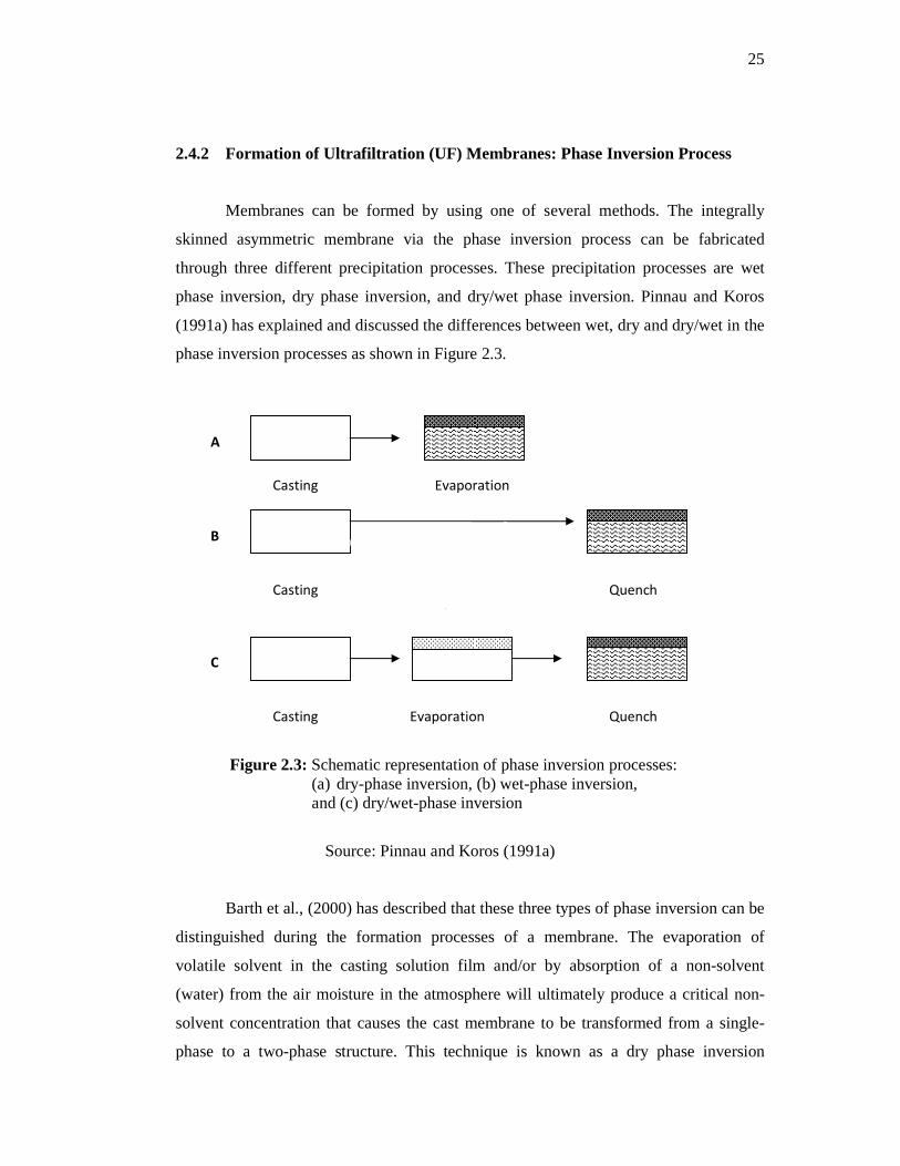
2.4.2 Formation of Ultrafiltration (UF) Membranes: Phase Inversion Process
Membranes can be formed by using one of several methods. The integrally
skinned asymmetric membrane via the phase inversion process can be fabricated
through three different precipitation processes. These precipitation processes are wet
phase inversion, dry phase inversion, and dry/wet phase inversion. Pinnau and Koros
(1991a) has explained and discussed the differences between wet, dry and dry/wet in the
phase inversion processes as shown in Figure 2.3.
Figure 2.3: Schematic representation of phase inversion processes: (a) dry-phase inversion, (b) wet-phase inversion,
and (c) dry/wet-phase inversion
Source: Pinnau and Koros (1991a)
Barth et al., (2000) has described that these three types of phase inversion can be
distinguished during the formation processes of a membrane. The evaporation of
volatile solvent in the casting solution film and/or by absorption of a non-solvent
(water) from the air moisture in the atmosphere will ultimately produce a critical non-
solvent concentration that causes the cast membrane to be transformed from a single-
phase to a two-phase structure. This technique is known as a dry phase inversion
Casting
Casting Evaporation
A
Evaporation Quench
B
Casting Evaporation Quench
C
Casting

26
process. The phase instability and structure formation can be also be achieved by the
exchange of solvent and non-solvent by immersing the polymer solution film into a
coagulation bath or a quench medium which contains a non-solvent. This phase
inversion process is often referred as a wet phase inversion process.
The dry/wet phase inversion process is the process of making a membrane by
combination of the dry phase inversion process and the wet phase inversion process.
This process takes two stages of processes. The first stage is the polymer casting
solution is exposed to the atmosphere for a certain period of time. The outermost region
of the polymer film undergoes phase separation induced by solvent evaporation. This
micro-phase separation process formed the membrane structure of the polymer solution
film. Then for the second stage, the polymer solution film immersed in a coagulation
bath. The bulk of the membrane structure is formed by solvent/non-solvent exchange
process during this stage (Pinnau and Koros, 1991a and Barth et al., 2000).
In the phase inversion process, precipitation of polymer solution is generally
well explained by using of a ternary mixing figure. During immersion of polymer
casting solution into a coagulation bath or a quench medium, the exchange process takes
place between non-solvent and solvent at the surface film of polymer casting solution.
In this process, solvent in the polymer solution comes out into the bulk of coagulation
bath and replaced by non-solvent from the coagulation bath. A non-solvent plays a role
as a precipitation agent in precipitation process and a gel is formed which is known as
membrane (Nunes and Peinemann, 2006).
Figure 2.4 shows a precipitation process of the ternary system of polymer
casting solution which contains polymer, solvent and non-solvent. Point A represents
polymer casting solution before immerse in a coagulation bath. Then, this cast solution
is immersed in the bath and a solvent-non-solvent exchange occurs. The triple
component mixture (polymer-solvent-non-solvent) reaches a solubility gap at point B.
Further exchange between these two components leads to phase separation which
results in a rigid polymer phase. Finally, all the solvent is replaced by non-solvent and
precipitation process is finished at point C. The final precipitation process has resulted a
polymer-rich phase (solid phase) which forms the membrane matrix at point D and a

27
polymer-poor phase at point L which represents the pore volume filled with non-solvent
(Rautenbach and Albrecht, 1989).
Figure 2.4: Triple component-dual phase separation for membrane production
Source: Rautenbach and Albrecht (1989)
2.5 TRANSPORT MECHANISMS OF ULTRAFILTRATION MEMBRAN E
The transport of MF and UF membranes has been well explained by Mulder
(1996). MF and UF membranes separate or remove particles or macromolecules from
colloid or dissolved macromolecules by sieve mechanism. Pressure is employed as a
driving force to make these membrane separations occurs. Solvent is forced to transport
through pores distributed across these membranes structure and this transport
mechanism is known as convective flow.
UF and MF membranes are porous membranes consist of a polymeric matrix in
which a large variety of pore geometries may possible as shown in Figure 2.5. Different
transports models have been developed to describe transport of permeate due to
different pore geometries exist in these two membrane processes. Generally, the
transport of permeate or the volume flow or the flux, J, through MF and UF membranes
can be described by Darcy’s law:
Polymer
Solvent L
Polymer Solution
Single phase area
Polymer composition
Dual phase area
A
B
D
C
non-solvent

28
� = �. ∆� (2.1)
where A is the permeability constant and �P is the pressure difference across the
thickness of the membranes. In this equation, the volume flow (flux) through the
membrane is directly proportional to the applied pressure.
Figure 2.5: Some characteristic pore geometries found in membranes: (a) Parallel cylindrical pores (b) close packed spheres
(c) a sponge-like structures
Source: Mulder (1996)
Figure 2.5(a) represents a number of parallel cylindrical pores perpendicular or
oblique to the membrane surface. The Hagen-Poiseuille equation (Eq. (2.2)) is used to
explain the volume flux (J) through these pores by assuming that all the pores have the
same radius.
� = ����
∆ ∆� (2.2)
where �P is the pressure difference across, �x is the membrane thickness, ɛ is the
surface porosity, r is the pore radius, η is the solvent viscosity and τ is the pore
tortuosity.

29
The ratio between the pressure differences (�P) across thickness of a membrane
(�x) is known as the driving force. This equation describes that the solvent flux is
proportional to the driving force and inversely proportional to the solvent viscosity. The
hydraulic permeability, Lp in terms of the porosity (ɛ), pore radius (r), pore tortuosity (τ)
and viscosity (η) has been introduced to the this equation.
�� = ���� (2.3)
So Eq. (2.3) substitute into Eq. (2.2)
� = �� ∆ ∆� (2.4)
Which means
����, � = ��������� ������ ���!�, �� × #��$�%& �'���, ∆� ∆�( (2.5)
In organic and inorganic sintered membranes or in phase inversion membranes
with a nodular top layer structure which consisting pore geometry of close packed
spheres system (Figure 2.5(b)), the performance of the membrane is represented by the
Kozeny-Carman relationship as shown in Eq. (2.6).
� = �)*�+(-.�)
∆ ∆� (2.6)
where ε is the volume fraction of the pores, S is the internal surface area and K is the
Kozeny-Carman constant, which depends on the shape of the pores and the tortuosity.
A sponge-like structure as depicted in Figure 2.5(c) presented the characteristic
pore geometry found in phase inversion membranes. The Hagen-Poiseulle or the
Kozeny-Carman relation can be used to explain and describe the volume flux permeates
through these asymmetric phase inversion membranes. It should be realized that the
convective flow as described by these equations only involves membrane-related
parameters and none which apply to the solutes.
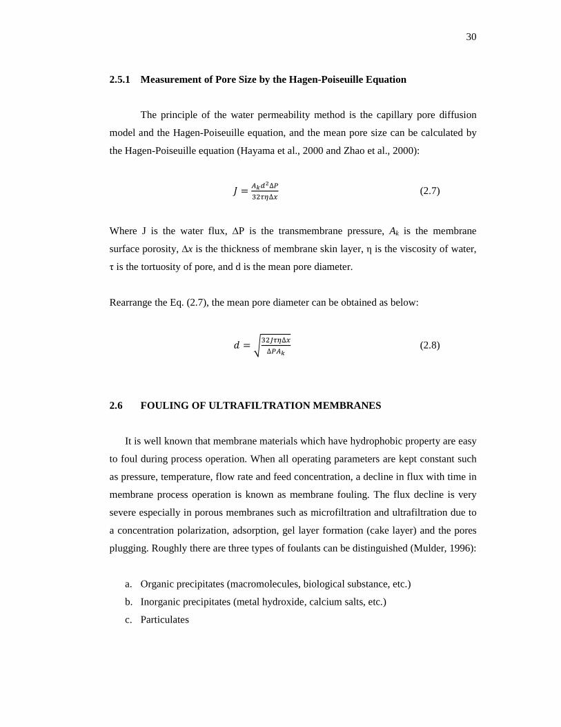
30
2.5.1 Measurement of Pore Size by the Hagen-Poiseuille Equation
The principle of the water permeability method is the capillary pore diffusion
model and the Hagen-Poiseuille equation, and the mean pore size can be calculated by
the Hagen-Poiseuille equation (Hayama et al., 2000 and Zhao et al., 2000):
� = 012∆ 34��∆� (2.7)
Where J is the water flux, ∆P is the transmembrane pressure, Ak is the membrane
surface porosity, ∆x is the thickness of membrane skin layer, η is the viscosity of water,
τ is the tortuosity of pore, and d is the mean pore diameter.
Rearrange the Eq. (2.7), the mean pore diameter can be obtained as below:
� = 5346��∆�∆ 01
(2.8)
2.6 FOULING OF ULTRAFILTRATION MEMBRANES
It is well known that membrane materials which have hydrophobic property are easy
to foul during process operation. When all operating parameters are kept constant such
as pressure, temperature, flow rate and feed concentration, a decline in flux with time in
membrane process operation is known as membrane fouling. The flux decline is very
severe especially in porous membranes such as microfiltration and ultrafiltration due to
a concentration polarization, adsorption, gel layer formation (cake layer) and the pores
plugging. Roughly there are three types of foulants can be distinguished (Mulder, 1996):
a. Organic precipitates (macromolecules, biological substance, etc.)
b. Inorganic precipitates (metal hydroxide, calcium salts, etc.)
c. Particulates

31
Fouling will depend on physical and chemical parameters such as concentration,
temperature, pH, ionic strength and specific interactions (hydrogen bonding, dipole-
dipole interactions). Hence, fouling phenomenon is very complex and difficult to
describe theoretically. Generally, the membrane or system performance which involves
fouling phenomenon can be written in terms of the convective flux as below:
7��� = 2�898:; <=�>?98@>[email protected]=ACD �?@8@A?:>? (2.9)
� = ∆ �EFGF
(2.10)
HA=A = HI + H>� + H; + HC + H� (2.11)
Where Rtot is total resistance comprises of Rm, membrane resistance, Rcp, concentration
polarization resistance, Rg, resistance of gel layer formation, Ra, adsorption resistance
and Rp, pore blocking resistance. Figure 2.6 depicted an overview of various types of
resistance towards mass transport across a membrane in pressure driven process.

32
Figure 2.6: Overview of various types of resistance towards mass transport across a membrane in pressure driven processes
Source: Mulder (1996)
Membrane fouling is the major limiting step in membrane technology. This
limiting factor reduces productivity as a result of low performance of membrane (Fersi
et al., 2009). Fouling has a negative influence on the economics of a membrane
operation process. It increases the operational cost due to usage of high energy, high
maintenance and cleaning cost. This problem has made slow acceptance in early
introduction of ultrafiltration membrane technology in industrial area applications.
There are several methods are employed to overcome or reduce fouling problems
include (Sutherland, 2005);
a. The choice of a membrane material as little susceptible to fouling as possible
b. Pretreatment of the feed solution such as addition of complexing agents, pH
adjustment and adsorption process (activated carbon).
c. The dosing of the surface of the membrane with substances than inhibit fouling
d. The increase of shear close to the membrane surface, either by increasing
suspension flow rates, or by moving the membrane in relation to this flow (by
33
rotation or vibration), or by mounting moving surfaces near to the membrane
(stirrer).
2.7 ULTRAFILTRATION BLEND MEMBRANES
In order to achieve a particular separation via a membrane process, the first step
is to select a suitable membrane material. An ideal material have reasonable mechanical
strength, maintain a high output and be selective for the desired permeate constituent
(Judds and Jefferson, 2003). Generally, polymer materials used in membrane fabrication
such as cellulose acetate has good fouling resistance, high flux and stable performance
but the drawbacks of this membrane material are poor mechanical strength, less stable
in organic solvents and less resistance to biological attack. Due to that, the alternative
polymers such as PSf, PVDF and PEI are offered better properties with high mechanical
strength, thermostable and chemical-resistant. The major disadvantages employed these
polymers in membrane fabrication that they are quite hydrophobic and it is not always
possible to prepare these membranes for specific applications.
The polymer such as CA has good surface properties but not good in mechanical
property and the other hand, the materials those posses’ good mechanical and chemical
resistant properties are hydrophobic materials. Due to this dilemma, the UF
manufacturers are still looking for the production of inexpensive membranes which
have good mechanical, thermal and chemical properties as well as high performance
that can be successfully used in specific UF applications. Almost 50% of the
commercial marketed MF and UF membranes are surface-modified membranes in order
to change their membrane chemistry properties to improve performance in targeted
applications. There are four common surface modification used by membrane
manufacturer which involve: (1) addition of a compatible modifier (such as a
hydrophilic or charged polymer) into the casting solution; (2) adsorption of a modifier
onto the membrane surface; (3) chemical or physicochemical post-treatments of the
surface (e.g., hydrolysis or gas plasma treatment); and/or (4) grafting or cross-linking a
modifier on the surface (Zeman and Zydney, 1996).

34
In surface modification, addition of hydrophilic polymer into casting solution
which contains hydrophobic polymer (main polymer) to produce better membrane
chemistry properties of the resultant membrane compared to the original membrane is
known as polymer blend. Polymer blend has been recognized as the cheapest, easiest
and versatile method in improving and modified polymer surface properties (Nady, et
al., 2011, and Yan and Wang, 2011). Polymer blend was also employed to develop a
new polymer membrane material which has high performance and low fouling as well
as has adequate mechanical, thermal and chemical properties which can be tailored for
many applications
Polymer blend is a physical process of blending the original polymer
with one or more polymers to produce a blend polymer that having more suitable
properties for membranes development (Nady et al., 2011, and Peng and Sui, 2006).
While, a material that is produced from two or more materials with different physical
and chemical properties which remain separate and distinct on a macroscopic level
within the finished structured is known as a composite membrane material (Nady et al.,
2011) such as polymer with chitosan (Mathew et al, 2008), polymer with ceramic
materials (Maximous et al., 2009, and Zhang et al., 2011) and polymer with metals
oxide (Wang et al., 2009). Table 2.6 shows a summary of investigated asymmetric
blend membranes that have been developed and studied by many researchers.
Generally, membranes prepared by blending hydrophobic polymers mixed with
hydrophilic polymers show higher membrane fluxes and better fouling tolerance in
comparing to the original membrane (Cho et al., 2011).

35
Table 2.6: Polymer blend membranes
Year Polymer blend Types of
membrane Researchers
1981 CN/PVP UF Tamura et al.
1981 PMMA/CAB Oxygen
permeability Yang et al.
1985 PAN/PVP PV Nguyen et al.
1992 PVDF/PMMA UF Nunes and Peinemann
1993 PESA/PEI UF Blicke et al.
1993 PS/PU UF Nguyen and Solomon
1995 PAN/PS UF Ai-lian and Qing
1996 PSf/PI Gas Separation Kapantaidakis et al.
1997 PSU/PEEK Pentene and
pentane separation van Zyl et al.
1999 CA/PU UF Sivakumar, et al.
1999a, b PSf/MPC Hemodialyis Ishihara et al.
2000 PSf/Span-80 Pervaporation Tsai et al.
2000 CA/PU UF Sivakumar et al.
2001 PSf/MPC Hemodialyis Hasegawa et al.
2002 CA/CPSU UF Sajitha et al.
2002 PU/SPS UF Malaisamy et al.
2004 CA/ERs and CA/SPS
UF Mahendran et al.
2004 CA/SPEEK UF Arthanareeswaran et al.
2005 PSf/PV(P-AN) UF Kim et al.
2005 PES/P(VP-S) UF Kim and Kim.
2006 PSf/PAA Ion-exchange UF M’Bareck et al.
2006 CA/PSf UF Sivakumar et al.
2006 PVDF/PES UF Wu et al.
2006 PVC/PVB UF Peng and Sui
2007a PSf/SPEEK UF Arthanareeswaran et al.
2007b CA/SPEEK UF Arthanareeswaran et al.
2007 PVDF/PFSA UF Lang et al.
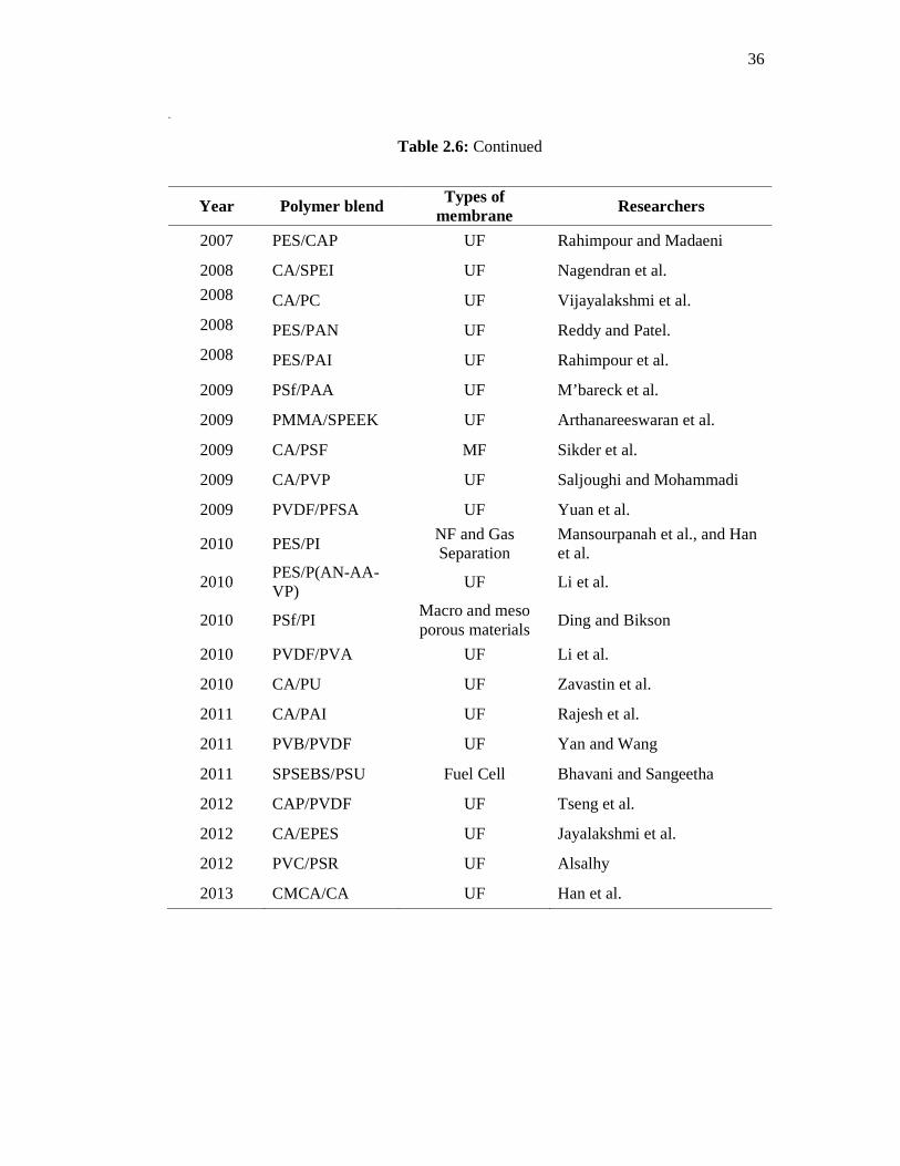
36
Table 2.6: Continued
Year Polymer blend Types of membrane Researchers
2007 PES/CAP UF Rahimpour and Madaeni
2008 CA/SPEI UF Nagendran et al.
2008 CA/PC UF Vijayalakshmi et al.
2008 PES/PAN UF Reddy and Patel.
2008 PES/PAI UF Rahimpour et al.
2009 PSf/PAA UF M’bareck et al.
2009 PMMA/SPEEK UF Arthanareeswaran et al.
2009 CA/PSF MF Sikder et al.
2009 CA/PVP UF Saljoughi and Mohammadi
2009 PVDF/PFSA UF Yuan et al.
2010 PES/PI NF and Gas Separation
Mansourpanah et al., and Han et al.
2010 PES/P(AN-AA-VP)
UF Li et al.
2010 PSf/PI Macro and meso porous materials
Ding and Bikson
2010 PVDF/PVA UF Li et al.
2010 CA/PU UF Zavastin et al.
2011 CA/PAI UF Rajesh et al.
2011 PVB/PVDF UF Yan and Wang
2011 SPSEBS/PSU Fuel Cell Bhavani and Sangeetha
2012 CAP/PVDF UF Tseng et al.
2012 CA/EPES UF Jayalakshmi et al.
2012 PVC/PSR UF Alsalhy
2013 CMCA/CA UF Han et al.

37
CA based membranes have been blended with other polymers to increase
chemical resistance, fouling resistance, thermal stability and mechanical strength. Many
studies have been conducted by blended CA with some hydrophilic polymers such as
epoxy functionalized poly(ether-sulfone) (EPES) (Jayalakshmi et al., 2012),
polycarbonate (PC) (Vijayalakshmi et al., 2008), sulfonated poly(ether imide) (SPEI)
(Nagendran et al., 2008), sulfonated poly(ether ether ketone) (SPEEK)
(Arthanareeswaran et al., 2007b), polysulfone (PSf) (Sikder et al., 2009, and Sivakumar
et al, 2006), sulfonated polysulfone (SPS) (Mahendran et al., 2004), carboxylated
polysulfone (Sajitha et al., 2002) and polyurethane (PU) (Zavastin et al, 2010, and
Sivakumar et al., 2000).
Poly(vinylidene fluoride), PVDF is a popular choice material for fabrication of
commercial UF and MF membranes. PVDF membranes are extensively employed in the
clarification of fruit juices especially in the clarification of lime juice due to PVDF can
resist exposure to limonene, which is present in citrus fruits and which will attack the
membranes such as CA, PSf and PES (Scott and Hughes, 1996). Even though this
polymer offered better performance in harsh operating condition compare to CA and
PSf membranes, but this polymer is classified as highly hydrophobic material (Nunes
and Peinemann, 2006).
Several attempts to make PVDF polar, more hydrophilic and less hydrophobic
have been described and investigated in the literatures via blending technique. Li et al.,
(2010) prepared poly(vinylidene fluoride)/poly(vinyl alcohol) (PVDF/PVA) hollow
fiber membranes while Yuan et al., (2009) and Lang et al., (2007) fabricated and
characterized poly(vinylidene fluoride)/perfuorosulfonic acid (PVDF/PFSA) hollow
fiber UF blend membranes with low-molecular weight cut off around 10,000 to 20, 000
Da. Wu et al., (2006) investigated the effects of solvent sorts, polyethersulfone (PES)
and polyvinylpyrrolidone (PVP) concentration on properties and morphology
PVDF/PES blend membranes. Poly(vinylidene fluoride)/poly(methyl methacrylate)
(PVDF/PMMMA) blend UF membranes were prepared by Nunes and Peinemann
(1992) in attempts to turn hydrophobic PVDF to more hydrophilic characteristic. In
these studies revealed that the addition hydrophilic organic polymers in PVDF

38
membranes improve the hydrophilicity and the anti-fouling property of the original
membrane.
PSf or PES is the most widely used polymers for preparation of UF membranes
(Nunes and Peinemann, 2006). PES is a quite interesting material for UF and MF
membrane manufacture but unfortunately, PES is also categorized as a hydrophobic
material (Nady et al., 2011). Recently, few researchers have been investigated the blend
of PES with hydrophilic polymers in order to develop anti-fouling PES blend
membranes such as polyethersulfone/polyimide (PES/PI) (Mansourpanah et al., 2010),
polyethersulfone/polysulfone-graft-poly(ethylene glycol) methyl ether methacrylate
(PES/PSf-g-POEM) (Yi et al., 2010), polyethersulfone/sulfonated polyethersulfone
(PES/SPES) (Rahimpour et al., 2010), polyethersulfone/poly (ether ether ketone)
(PES/SPEEK) (Lau and Ismail, 2009), polyethersulfone/poly (amide-imide) (PES/PAI)
(Rahimpour et al., 2008), polyethersulfone/cellulose acetate phthalate (PES/CAP)
(Rahimpour and Madaeni, 2007) and polyethersulfone/pluronic polymers (Wang et al.,
2006). These studies shown a promising performance and anti-fouling of PES blend
ultrafiltration membranes compare to the virgin PES membrane via blending method.
2.8 POLYSULFONE BLEND MEMBRANES
Polysulfone is an excellent polymer for membrane fabrication with high
mechanical, electrical and chemical resistant properties. This polymer remained
relatively constant over a broad temperature range from -150°F to 300°F. Polysulfone is
exceptional in steam up to 300°F. The chemical stability of PSf is much higher than
cellulose polymer. The preparation of ultrafiltration membranes from PSf solutions
leads to a large variety of porous asymmetric structures, which can be controlled by
changing the composition of the solvent mixture (Peinemann and Nunes, 2001).
In membrane manufacturing, PSf allows reproducible formation of high quality
membranes and forms membranes with different pore sizes. Moreover, it is generally
ease to prepare asymmetric membranes by the immersion phase inversion method using
water as a coagulant. Porous PSf membranes with a dense and thin top layer were
initially prepared from a solution in a proper mixture. The addition of volatile non-
solvents to the casting solution leads to the formation of even thinner top layers. A non-
39
solvent slightly increases the solution viscosity and favors a sponge-like structure with
finger-like cavities (Peinemann and Nunes, 2001).
More open asymmetric PSf supports have been used for ultrafiltration or as
support for composite membranes. PSf is selected as the membrane material because of
its commercial availability, ease of processing and favorable selectivity-permeability
characteristics. It possesses good mechanical, thermal and chemical properties. PSf is
stable to wide pH levels (from 2 to 13) and therefore can withstand many types of
cleaning methods. It has fairly good chemical resistance and shows a hydrolytic and
oxidative stability.
In spite of its good characteristics as membrane material for polymeric
membrane, the hydrophobic surface of polysulfone also brings obstacles with severe
fouling during ultrafiltration process, in particular during protein or enzyme separation.
This fouling phenomenon contributes mainly from protein deposited onto membrane
surface and the permeate flux of fouled membrane decreases up to less than 5% of
initial flux with the increase of permeation time (Mulder, 1996). Another factors
contributing to fouling are surface properties (chemistry, morphology, etc.),
hydrodynamic conditions, physical-chemical environment of feed solution, and solute
concentration (Kim et al., 1992).
The extent of protein deposition onto membrane surface depends on the
interactions between foulants and membranes, among the foulants and between foulants
and cleaning chemicals. Hydrophobic interactions between the membrane surface and
protein molecules however become one of the dominant factors for this complicated
mechanism (Marshall et al., 1993). Therefore, deposition of protein molecules on the
membrane surface can be reduced by modifying hydrophobic membrane surface to
hydrophilic membrane surface. And it is also easy to clean the hydrophilic surface of
membranes because adsorbed protein molecules are more easily removed from the
surface of membranes (Kim et al., 2002).
40
Although the modification of PSf has been widely explored using a few
techniques such as use of additive and oxygen plasma treatment (Kim et al., 2002), such
problem still remain to be unsolved which consequently reduce the membrane
performance and increases the process complexity and manufacturing costs. Thus,
research efforts have been continued to find out an excellent technique such as polymer
blend technique to counter this problem during protein ultrafiltration.
It is well known that polysulfones (PSf) are the preferred polymer materials for
many types of membrane processes from microfiltration to gas permeation but this
hydrophobic polymer needs to be modified to obtain high fluxes, less fouling, low
maintenance cost and widen application in various range of industries. Some researchers
such as Nguyen and Solomon (1993), Ai-Lian and Cheng Qing (1995), Tsai et al.,
(2000), Kim et al., (2005), M’bareck et al., (2006), M’bareck et al, (2009), Sikder et al.,
(2009), Ding and Bikson (2010), and Bhavani and Sangeetha (2011) had fabricated
PSf membranes via blending PSf with hydrophilic polymers in order to improve
hydrophilicity properties and performance of the virgin PSf membranes in various
membrane applications.
Nguyen and Solomon (1993) developed microporous composite
polysulfone/polyurethane (PSf/PU) hollow fiber membranes via new one-step process.
They used low reactivity polyurethane prepolymer which was blended with polysulfone
in casting solutions. A polymerization catalyst was used in coagulation bath in order to
promote the polymerization of prepolymer at the membrane/precipitation solution
interface. This catalyst has polymerized polyurethane prepolymer by cross-linking
reaction at polysulfone/polyurethane membranes surface. The more polyurethane cross-
linked on the blend membrane surface will produced the microporous blend membranes
which possessed excellent flux and very low protein adsorption due to increase in their
hydrophilicity properties.
Ai-Lian and Qing prepared a partly miscible casting solution containing
polyacrylonitrillic/polysulfone (PAN/PS) blend and the PAN/PS blend membranes were
prepared according to the Loeb-Sourirajan method. In their investigation, they were
found that PAN/PS blend UF membrane has good performance with an especially high

41
flux compared to PAN membrane (Ai-Lian and Qing, 1995). In pervaporation
performance studies, asymmetric PSf membranes were blended with a surfactant (Span-
80) in the casting solutions and the blend membranes were prepared via the wet-phase
inversion method (Tsai et al., 2000). The effect of surfactant content on the surface
morphology and pervaporation performance of the PSf membranes were observed.
Addition of surfactant suppressed macrovoids size in the asymmetric PSf membranes
and consequently increases the separation factor while decrease the permeation rate. PSf
membranes blended with 15 wt.% Span-80 content produces the optimum pervaporation
results.
Kim et al., (2005) synthesized poly(1-vinylpyrrolidone-co-acrylontrile)
copolymers, P(VP-AN) via radical copolymerization and this copolymers was used as a
blended polymer with the hydrophobic polymer, polysulfone. The casting solutions
containing 2 wt% to 16 wt% of P(VP-AN) were formed miscible blend with PSf to
obtain hydrophilic blend ultrafiltration membranes that developed by phase inversion
process. The resultant membranes, PSf/P(VP-AN) exhibited better performance in
solute rejection and flux than membrane prepared from PSf or PSf/PVP.
Generally, a soluble polymer, polyacrylic acid (PAA) is used as a complexing
agent in assisting ultrafiltration process to remove heavy metals from waste water via
complexation-ultafiltration or also known as polymer enhanced ultrafiltration.
Unfortunately, this technique decreased the hydrophilicity of membrane and fouling
problem become severe. Mbareck et al., (2006) and Mbareck et al., (2009) introduced
an efficient and economical method for fabricating ion-exchange ultrafiltration
membranes for heavy metals removal.
In this new technique, PSf anf PAA were separately dissolved in DMF solvent
and then these two solution were blended to form membrane casting solutions. PSf/PAA
membranes were fabricated according to the wet phase inversion method. They had
made PSf/PAA blend membranes with semi-interpenetrating PSf and PAA network.
The high efficiency in rejection of lead, chromium and cadmium from water was
attributed to the complexation metal ions and carboxylate groups (-COO-) on the inner

42
surface of pores and membrane matrix. These high performance membranes make this
new method attractive for metals separation in water and waste water treatment.
Sikder et al., (2009) focused on synthesized and characterized of cellulose
acetate-polysufone blend microfiltration membrane for microbial cells separation from
lactic acid fermentation broth in a continuous process. The PSf/CA blend membrane
was successful 100% retention of microbial cells from the broth at reasonably high
permeation broth flux in a continuous cross-flow membrane module integrated with the
fermenter. The promising results in this integrated system pave the way for scale up for
other similar systems as well. Ding and Bikson (2010) has prepared a novel macro and
meso porous polymeric membrane materials from miscible blend of
polysulfone/polyimide (PSF/PI) by chemical decomposition of polyimides. Macro and
meso porous films with uniform pore sizes were developed via this novel approach.
This blend films is potential to apply as membranes in nanoseparations, bioseparations,
scaffoldings and substrates.
The potential polymer blend of SPSEBS/PSU in the proton exchange membrane
for fuel cell application has been fabricated by Bhavani and Sangeetha (2011). In their
investigation, they revealed that SPSEBS very well blended with PSU. The blended
polymer has improved mechanical property and thermal stability of SPSEBS
membrane. The introduction PSU into SPSEBS polymer solution has produced a
promising SPSEBS/PSU blend membranes for the usage in direct methanol fuel cell
(DMFC) and electrolyte membrane fuel cell (PEMFC).

43
2.9 ADDITIVES IN BLEND MEMBRANES
Many researchers have been investigated the effect of different types of organic
and inorganic additives on membrane performance and morphology of polymer blend
membranes. The role of organic and inorganic additives is to create a spongy like
membrane structure by interruption of macrovoid formation, enhance pore formation,
improve pore interconnectivity and/or introduce hydrophilicity. Polyvinylpyrrolidone
(PVP) and polyethylene glycol (PEG) are two popular organic additives used in
membrane fabrication due to these additives strongly influenced on the membrane
characteristics in terms of pore size, permeate flux and the solute rejection rates (Ani
and Lee, 2006). Others additive such as glycerol, alcohols, dialcohols, water,
formamide, mineral fillers or the mixture of them are employed in membrane research
studies which affect the properties of the final membranes (Ani et al., 2010).
In fabrication of polymeric ultrafiltration (UF) membranes, various organic and
inorganic additives were tested for polyacrylonitrilic/polysulfone (PAN/PS) blend UF
membranes (Ai-lian and Qing, 1995). The results showed that some effective additive
for PAN and PSf did not suit for PAN/PSf blend membranes and the addition 95%
acetic acid as additive gave the best performance of Bovine Serum Albumin (BSA)
rejection. Sivakumar et al., (1999) studied the effect of different concentration of non-
soluble swelling additive, PVP on the performance of ultrafiltration application of
cellulose acetate-polyurethane (CA/PU) blend membranes. An increase in addition of
PVP concentration from 0 to 2.5 wt% reduced the rejection of proteins while water flux
and solute flux increased respectively due to increase of membrane pore size and
hydrophilicity of blend membranes.
Sivakumar et al., (2000) further employed PVP additive with concentration from
0 to 7.5 wt% in CA/PU blend membranes to study membrane compaction, pure water
flux, water content, membrane hydraulic resistance and morphology of the membranes.
In their study showed that PVP plays a key role in controlling the pore size and
miscibility of the blends, and these blends membranes were effectively better
performance for separation of proteins and metal ions than pure membrane.
44
Sivakumar et al., (2006) prepared CA/PSf blend membranes by using PVP K30
as an additive at various concentration of 0 wt% to 7.5 wt%. The results showed that an
increase in flux and Molecular Weight Cut-Off (MWCO) of blend membranes with
increasing PVP concentration may be due to fast rate of leachability of PVP during
precipitation process, which in turn produce a large pore on membrane surface. Wu et
al., (2006) reported the same observation that PVP concentration in PVDF/PES blend
has much influence on properties and morphology of these blend membranes. Small
amount of PVP concentration (2 wt.%) in PES/CAP blend membrane improved the
morphology, mechanical strength, permeability and protein rejection of the PES/CAP
blend membrane (Rahimpour and Madaeni, 2007).
Malaisamy et al., (2002) investigated the effect additive concentration, PEG 600
on polyurethane and sulfonated polysulfone (PU/SPSf) blend ultrafiltration membrane.
The morphology of the resultant membrane extensively changed which in turn altering
the structural properties and then improving the flux performance. PEG 600 additive
was claimed play major influence on characteristics of cellulose acetate/epoxy resin
(CA/ER) blend ultrafiltration membranes such as pure water flux, membrane resistance
and water content (Mahendran et al., 2004).
The effect of different molecular weights of PEG namely as PEG 200, PEG 400
and PEG 600 which represent their molecular weight respectively, in PES membranes
has been studied by Ani et al. (2007). The presence of higher molecular weight of PEG
has increased pure water permeation, pore size and MWCO of PES membranes due to
increase the number and the size of macrovoids as well as the surface roughness of the
membranes. Vijayalakshmi et al., (2008) reported that the presence of PEG 600 in
cellulose acetate/polycarbonate (CA/PC) blend casting solutions had a considerable
impact on the rejections and permeate flux of the proteins and metal ion complexes. An
increase in additive concentration had increased permeate flux but solutes rejection
were decreased due to increase in pore size of the blend membranes.

45
Vijayalakshmi et al., (2008) and Nagendran, et al., (2008) explained that
increasing PEG 600 concentration in cellulose acetate/polycarbonate (CA/PC) and
cellulose acetate/sulfonated poly(ether imide) (CA/SPEI) blend membranes
respectively, tends to increase formation of pores and hence subsequently, the rejection
of metal ions was decreased while the permeate flux increased. Arthanareeswaran et al.,
(2010) investigated the effects of PEG 600 on PSf/SPEEK blend membranes and the
results revealed that increased in the concentration of PEG 600 in casting solutions
resulted in improving performance and hydrophilicity of these membranes. PEG 600
also plays important role in organic-inorganic composite membranes by enhancing flux
recovery ratio and decreased the total fouling resistance (Arthanareeswaran et al., 2009).
2.10 SHEAR RATE
In the last 30 years of membrane technology development, many efforts has
been done in aspects of membrane materials, dope preparation, fabrication technology,
and fundamental mechanisms for developing high performance membranes (Kusworo et
al., 2008 and Ismail et al., 2006). In that period, the effect of rheological factors such as
shear rate on membrane development has just little attention on the membrane research
study. However recently, this fundamental research is recognized as one of the
important parameters in membrane fabrication process in order to improve fundamental
knowledge of membrane manufacture and performance in ultrafiltration, nanofiltration
and gas separation processes (Idris et al., 2003, and Ismail et al., 2006).
The effect of low and high shear rate on selectivity of CO2/CH4 of asymmetric
polysulfone and polyacrylonitile flat sheet membrane has been tested by Shilton et al.,
(1997). Polarized reflection i.r. dichroism was successfully used to determine molecular
orientation occurred in the membranes at low and high shear rate. The experimental
results showed that the degree of molecular orientation was enhanced with high shear
rate which in turn exhibited more selectivity. The effect of shear rate on molecular
orientation was more pronounced in the polyacrylonitrile compare to polysulfone
membrane.
46
Sharpe et al., (1999) conducted a study of extrusion shear and forced convection
residence time in the spinning of polysulfone hollow fiber membranes for gas
separation. They found that membranes should be spun at high shear rate and at
optimized residence time to minimize surface defects and hence subsequently enhanced
selectivity and high flux. Chung et al., (2000a) investigated the effect of shear rate
within spinneret on polyethersulfone hollow fiber membranes and for the first time, it
was found the existing of a certain critical value of shear rate. When the shear rate was
increased, the separation performance increased while the flux decreased dramatically
but further increment of shear rate resulted in decreased in separation performance
while the flux did not change. Chung et al., (2002) also have demonstrated there was a
certain critical value of shear rate by characterized the outer surface morphology of
polethersulfone hollow fiber ultrafiltration membranes via an atomic force microscope
(AFM).
Idris et al., (2003) has studied the pure influence of shear rate that induced
molecular orientation in reverse osmosis hollow fiber cellulose acetate membranes by
using Fourier transform attenuated total reflection (ATR-FTIR). Their experiments
revealed that ATR-FTIR can be used to determine the degree of molecular orientation in
the sheared membranes. As Chung’s finding, they also suggested an optimum shear rate
induced a certain degree of molecular orientation to yield membrane morphology with
optimum separation performance. Then, Ng et al., (2004) examined molecular
orientation induced by rheological parameter on the surface of Polysulfone flat sheet
membranes by using ATR-FTIR. The gas selectivities of O2/N2 and CO2/CH
significantly increased with increased in shear rate due to greater molecular orientation
in the skin layer of the PSf membranes.
The effect of dope extrusion rate (DER) on morphology of hollow fibers
membrane for ultrafiltration process was investigated by Ismail et al., (2006). The DER
was varied from 2.0 to 4.0 cm3/min with 0.5 cm3/min increments in order to study the
fibers performance and morphology. In their investigation, they found that an increase
in DER decreased flux but increased solute rejection. The rejection increased with
increasing DER until it reached maximum separation performance and then, further
increment of DER decreased the solute rejection. In this study, they suggested that the

47
increasing in rejection was due to the outer skin layer becomes apparently thicker and
denser, and further increased DER after critical performance possibly made the outer
skin structure are less tighten.
All these phenomena are related to molecular orientation occurs at membrane
surface at different DER during fabrication process. The higher molecular orientation
was responsible for higher separation performance of ultrafiltration membrane. Ismail
and Hassan (2006) employed the combination of irreversible thermodynamic model,
solution-diffusion model (Spiegler-Kedem equation), steric-hindrance pore (SHP) and
Teorell-Meyers (TMS) model to study transport mechanisms and to determine the
membrane structural properties of PSf nanofiltration membranes fabricated at different
polymer concentrations and at different shear rates.
Based on the electrolytes transport performance test and modeling data, the
results showed that increased in shear rate and polymer concentration has increased salt
rejection until it achieved the optimum or the critical shear rate. An orientation of
molecular polymer chains at the membrane skin layer to a certain extent during different
shear rate affected the performance and membrane structural properties.
Polyimide/polyethersulfone (PI/PES)-zeolite 4A mixed matrix membranes were
prepared and cast at different shear rates by Kusworo et al., (2008). These flat sheet
membranes were tested via O2/N2 gas separation performance and their molecular
orientation has viewed through the Infrared (IR) absorption spectra study.
In the gas separation study, Kusworo et al., (2008) found that molecular chains
become more aligned at 581 s-1 of shear rate as shown via normalized of different FTIR
spectrum. An optimum shear rate for PI/PES-zeolite 4A mixed matrix membranes
existed at this shear rate and it was proved by optimum selectivity of O2/N2 and
permeability of O2. Nora’aini et al., (2010) studied the effect of shear rate on the flat
sheet of Polyethersulfone nanofiltration membranes for ammonia-nitrogen removal.
They used casting speed at 5 s, 10 s, 15 s, 20 s, 25 s and 30 s, which in turn the shear
rate of membrane casting process decreased by increasing the casting speed of a casting
knife. Their experimental works revealed that the pore size was reduced while the
membrane thickness increased by increasing the shear rate and hence subsequently
48
increased the membrane selectivity. A casting of 10 s or shear rate at 200 s-1 was found
the most recommended parameter condition due to its favorable separation
performance.
2.11 EVAPORATION TIME
Nowadays, most commercial available membrane obtained by phase inversion.
It is a process whereby a polymer is transformed in a controlled manner from a liquid to
a solid state. The simplest technique for preparing phase inversion membrane is
precipitation by solvent evaporation. In this method a polymer is dissolved in a solvent
and the polymeric solution is cast on a suitable support. The solvent is allowed to
evaporate in an inert atmosphere in order to exclude solvent from the polymeric solution
to form a dense homogeneous membrane (Mulder, 1996). This inversion method is
known as dry phase inversion. The time required to evaporate solvent from the
polymeric solution during membrane fabrication process is known as evaporation time.
There are many researchers studied on the effects of evaporation time during dry
phase inversion process on membranes characteristics and performance. It is due to
different membrane morphology and properties can be obtained for tailor-made
membranes by varies the evaporation time. The integrally skinned asymmetric
membrane can be developed by introducing dry phase inversion for polymer casting
solution before wet phase inversion take place during fabrication of asymmetric
membranes. The combination of these two techniques was reported successful in
producing membrane with high productivity and selectivity.
The combination of ultrathin and defect-free skin layers are generally not
achieved for membranes made by the wet phase inversion process. The membranes
were fabricated by wet phase inversion processes always contains defects due to
incomplete coalescence of the skin layer. Integrally skinned asymmetric membranes can
be formed by dry/wet phase inversion process. It is due to phase separation is induced in
the outermost region of the cast membrane during an evaporation step, while liquid-
liquid phase separation in the bulk films occurs subsequently during a quench step
(Ahmed, 2009).
49
Pinniau et al., (1990) demonstrated that essentially defect-free membranes with
skin layer thickness as thin as 500 Å can be formed from a variety of polymers by
dry/wet phase inversion process using forced-convective evaporation. Pinnaiu (1991)
presented a physically meaningful mechanism for the formation of ultrathin and defect-
free skin layers of membranes made by dry/wet phase inversion. Pinnau and Koros
(1991a) have summarized the empirically developed rules for the formation optimized
asymmetric membranes by dry/wet phase inversion process. Pinnau and Koros (1991b)
demonstrated clearly that the physical processes which occurred during the evaporation
step were of utmost importance for the skin layer formation of asymmetric membranes
made by dry/wet phase inversion.
Pesek and Koros (1993) investigated the effects of aqueous quenched
asymmetric polysulfone membranes prepared by dry/wet phase separation and they
found that this technique produced the polysulfone membranes with ultrathin selective
layer, which can be made as thin as 200 to 800 Å. Pesek and Koros (1994) also reported
that a dry/wet spinning process produced very thin, defect free and small diameter of
hollow fiber membranes for gas separations. Furthermore, the defect-free selective skins
of these hollow fibers were performed prior coagulation in less 0.5 s compared to 10 to
15 s that allowed for flat sheet membranes prepared by this same dry/wet process.
Ohya et al., (1997) studied on molecular weight cut-off performance of aromatic
polyimide membrane and they revealed that shortened the evaporation time decrease the
thickness of the active layer and consequently increased the molecular weight cut-off of
the membrane surface which in turn decreased membrane resistance. In other words, an
increase in evaporation time formed membrane with thick active layer and small
molecular weight cut-off and hence, reduced the permeate flux. Chung and Hu (1997)
and Tsai, et al., (2002) investigated on the effects of the air gap during hollow fiber
fabrication process and they found that the increasing air gap length enhanced a greater
extent of molecular orientation. Ren et al., (2008) observed that the hollow fiber
membranes fabricated with air gap not less than 1 cm strongly influenced the
performance and a relatively low permeation flux and small MWCO were obtained due
to the accumulated stress was released greatly in the air gap and some big pores were
suppressed.
50
Hasbullah et al., (2011) also studied the effects of air gap on the preparation and
performance of polyaniline (PAni) asymmetric hollow fiber membranes towards gas
separation. They discovered a substantial improvement in the gas performance of the
PAni hollow fiber membranes as the air gap was varied. It was observed that the gas
flux was significantly decreased while the selectivity was increased with an increase in
air gap from 2.5 to 50 cm. SEM and the mechanical properties results proved that
molecular orientation and skin layer thickness increased with an increase in air gap
which in turn enhanced the gas separation performance.
Recently, Ismail et al., (2011) successful developed hyperthin-skinned and high
performance asymmetric polyethersulfone membranes for gas separation. Evaporation
time and casting shear have been identified as the dominant fabrication parameters in
controlling skin layer thickness and skin integrity. These combination effects improved
membrane performance in terms of O2 and N2 separation. The optimum range was
found to be in the range of 149 to 447 s−1 and 10 to 14 s for the shear rate and the
evaporation time respectively. The thinnest skin layer thickness was 538±95.6 Å.
2.12 CHARACTERIZATION OF ULTRAFILTRATION MEMBRANE
Generally, membrane processes cover a wide range of separation problems with
a specific membrane structures. Thus, membrane may differ significantly in their
structures and consequently in their functions. Hence, membrane characterization is
important in order to determine the structural and morphological properties of a given
membrane. Many attempts have been made to relate membrane structures to transport
phenomenon in a membrane process in order to enhance fundamental knowledge of
separation performance.

51
2.12.1 Water Content and Contact Angle
Water content and contact angle are two physical measurements of membranes
property in order to know quantitatively hydrophilicity of the membranes. In water
content measurement, membranes are soaked in water for overnight and then the
difference of weight between dry and wet membranes is used to determine the
percentage of water content. This measurement is indirectly describes the hydrophilic
nature of the corresponding membranes and the pure water flux can be predicted based
on this information.
The importance of contact angle information is used to study hydrophilicity
property of polymeric membranes. The terms of water contact angle, θ, presented
hydrophilicity of solid surfaces (Zeman and Zydney, 1996). The contact angle of
polymeric membranes can be measured based on the principle of the degree of
wettability of water droplets on the membrane surface. The interaction between water
and polymeric materials is known as wettability. A droplet of water is placed upon a
surface of polymeric membrane and then, the contact angle (θ) of liquid droplet is
measured (Mulder, 1996).
Figure 2.7 is schematically shown the effect of the equilibrium contact angle, θ,
on the pore intrusion phenomenon. Hydrophilic surfaces have the contact angle, θ, close
to 0o (i.e., cos (θ) = 1), while for low affinity of membrane surface, the contact angle, θ,
will have a value greater than 90o, (i.e., cos (θ) ≤ 0). For hydrophilic materials, the
liquid will penetrate spontaneously into the pores of the membrane while no liquid
intrusion occurs on hydrophobic membrane surface (Mulder, 1996 and Zeman and
Zydney, 1996).
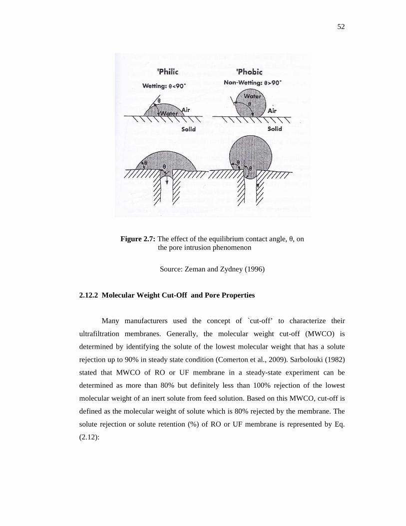
52
Figure 2.7: The effect of the equilibrium contact angle, θ, on the pore intrusion phenomenon
Source: Zeman and Zydney (1996)
2.12.2 Molecular Weight Cut-Off and Pore Properties
Many manufacturers used the concept of `cut-off’ to characterize their
ultrafiltration membranes. Generally, the molecular weight cut-off (MWCO) is
determined by identifying the solute of the lowest molecular weight that has a solute
rejection up to 90% in steady state condition (Comerton et al., 2009). Sarbolouki (1982)
stated that MWCO of RO or UF membrane in a steady-state experiment can be
determined as more than 80% but definitely less than 100% rejection of the lowest
molecular weight of an inert solute from feed solution. Based on this MWCO, cut-off is
defined as the molecular weight of solute which is 80% rejected by the membrane. The
solute rejection or solute retention (%) of RO or UF membrane is represented by Eq.
(2.12):

53
H�K��!�'% (%) = M1 − PQPR
S × 100 (2.12)
Where Cp and Cf are the solute concentrations in the permeate and the feed solutions,
respectively.
Sarbolouki developed figures and mathematical model which correlates between
the molecular weight cut-off and the membrane pore size. In this correlation, the sieving
effects at the entrance are only to be considered since the molecular weight of the inert
solute retained depends only on the structure of the upstream of the membrane. Eq.
(2.13) represents the entrance sieve models for Rejection (%) values greater than 80%.
H�K��!�'% (%) = 100 U�V HV( W (2.13)
Where H X and ā are the average pore size and the solute radius, respectively.
Figure 2.8 shows a general correlation between the average membrane pore size
and the solute molecular weight at Rejection (%) = 80, 85, and 95%. By using this
figure, the average pore size of the corresponding membrane can be directly read off
once the solute molecular weight of Rejection (%) = 80, 85, and 95% has been
determined. The pore properties of the RO or UF membranes can be determined by
calculation of surface porosity and pore density of the membrane, respectively. The
surface porosity of the membrane, ε, is calculated based on the following equation.
Y = 3Z�6EV∆ (2.14)
Where HV is the average membrane pore size (cm), η is viscosity of the permeate
(g/cm.s), J is pure solvent flux (cm/s), and �P is the applied pressure (dyn/cm2).
Since knowing ε and HV, the pore density of the corresponding membrane, n
(pore/cm2), can be calculated by Eq. (2.14)
% = �ZEV (2.15)
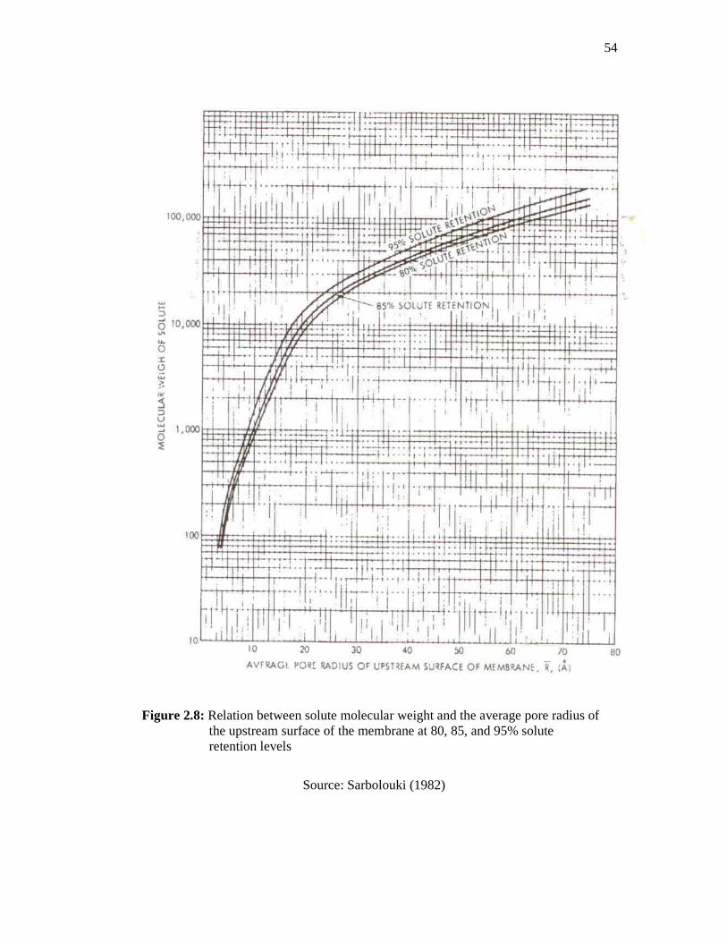
54
Figure 2.8: Relation between solute molecular weight and the average pore radius of the upstream surface of the membrane at 80, 85, and 95% solute retention levels
Source: Sarbolouki (1982)
55
2.12.3 Surface Characterization
The membrane structures are characterized using the Scanning Electron
Microscopic (SEM). The morphological structures of the surface skin layer, pores and
cross section of membranes can be viewed at different magnificent through SEM. SEM
is a very useful characterization tool in research and development of membrane due to it
provides direct and practical structural membrane information, couple with fast
response and impressive analytical output. In SEM, a narrow beam of high-energy
electrons hits the membrane and the secondary electron with low energy are liberated
from atoms in the membrane surface produced image of membrane on the screen or the
micrograph. The pore size, the pore size distribution and the surface porosity also can be
obtained from the micrograph. Moreover, the geometry of the pores can be clearly
visualized via this technique (Zeman and Zydney, 1996 and Mulder, 1996).
2.13 RHEOLOGICAL PROPERTIES
In fabrication of a flat sheet asymmetric membrane, polymer casting solution is
cast and flows with a certain thickness between a support plate and a knife blade, and
then immersed into a coagulation bath for precipitation process. The properties study of
the flow-fluid is important in order to relate its properties with membrane performance
and morphological structural analysis. The study of the deformation and flow of the
polymer casting solution is known as rheological study (Brookfield, 2004). Sharpe
(1999) and Chung et al., (2000b) explained that the polymer casting solutions were cast
at certain shear rate will decreased its viscosity due to molecular orientation occurred in
the polymer films. The decrease in viscosity tends to create slight imperfections in the
membrane skin layer due to deterioration of molecular orientation takes place at the skin
membrane surface layer
Viscosity is the measure of the internal friction of a fluid. If the greater internal
friction is existed, so the greater amount of force is required to flow the fluid. This
phenomenon is called shear. Hence, viscosity of a fluid is defined as a measure of its
resistance to shear or angular deformation (Finnemore and Franzini, 2002).
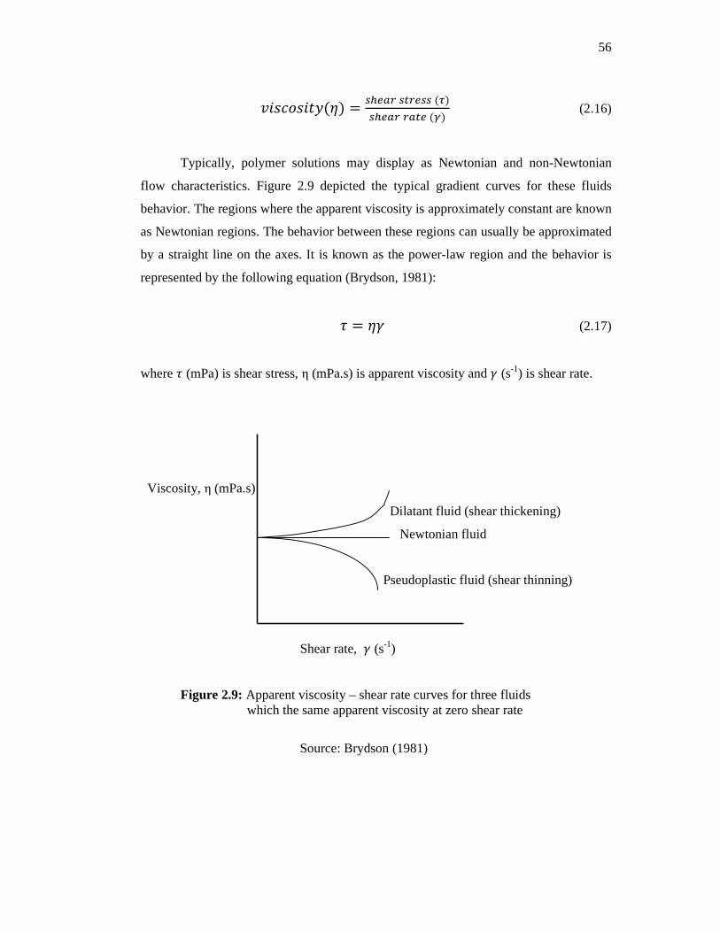
56
$�[�'[�!�(\) = @]?C� @A�?@@ (�)@]?C� �CA? (^) (2.16)
Typically, polymer solutions may display as Newtonian and non-Newtonian
flow characteristics. Figure 2.9 depicted the typical gradient curves for these fluids
behavior. The regions where the apparent viscosity is approximately constant are known
as Newtonian regions. The behavior between these regions can usually be approximated
by a straight line on the axes. It is known as the power-law region and the behavior is
represented by the following equation (Brydson, 1981):
_ = \` (2.17)
where _ (mPa) is shear stress, η (mPa.s) is apparent viscosity and ` (s-1) is shear rate.
Viscosity, η (mPa.s)
Dilatant fluid (shear thickening)
Newtonian fluid
Pseudoplastic fluid (shear thinning)
Shear rate, ` (s-1)
Figure 2.9: Apparent viscosity – shear rate curves for three fluids which the same apparent viscosity at zero shear rate
Source: Brydson (1981)

57
A non-Newtonian fluid is broadly defined as the non linear relationship between
shear stress and shear rate. There are two types of non-Newtonian fluids: dilatant fluid
(shear thickening) and pseudoplastic fluid (shear thinning) (Eposito, 1998). It is
described by the given equation (Brydson, 1981)
\ = a`: (2.18)
Where n is the flow behavior index (dimensionless) and k is the consistency index
(Pa.s).
Upon using the relationship between the shear stress, apparent viscosity, and the
shear rate, the power-law model is obtained and n is called the power-law index. Note
that n =1 corresponds to Newtonian behavior. Typically, if n < 1, a shear thinning fluid
is obtained, which characterized by a progressively decreasing apparent viscosity with
increasing shear rate. If n > 1, a shear-thickening fluid in which the apparent viscosity
increases progressively with increasing shear rate is observed. Generally, polymer
casting solutions used in membrane fabrication process are shear thinning fluid due to
its viscosity decrease with increasing shear rate which in turn affects the characteristics
and performance of the respective membranes.
CHAPTER 3
MATERIALS AND METHODOLOGY
3.1 INTRODUCTION
The preparation of PSf/CAP/PVP blend membranes can be influenced by many
factors. Those factors include selection of materials (such as polymer, solvent and
additive), fabrication conditions and coagulation bath composition. In this study,
polysulfone was employed as the main back-bone polymer to produce blend membranes
which consist of different composition blend of PSf and CAP in the PSf/CAP blend UF
membranes before this blend membrane was added with PVP to produce PSf/CAP/PVP
blend membrane. In order to produce high performance asymmetric PSf/CAP/PVP
blend membranes, the factors of polymer composition, additives concentration, shear
rates and evaporation time which affects the resultant membranes characteristics and
performance were investigated throughout this study.
The fabricated membranes were characterized in terms of water content, contact
angle, membrane permeability coefficient and porosity of membranes. Molecular weight
cut-off (MWCO) and pore properties of the upstream surface membranes (average pores
size and pores density) were determined to relate the permeation and rejection of
solutes. The membranes performance was investigated through pure water flux and
proteins separation tests by using a dead-end cell ultrafiltration unit. SEM was
employed to study morphological structures of membranes that affected the membrane
separation performance.
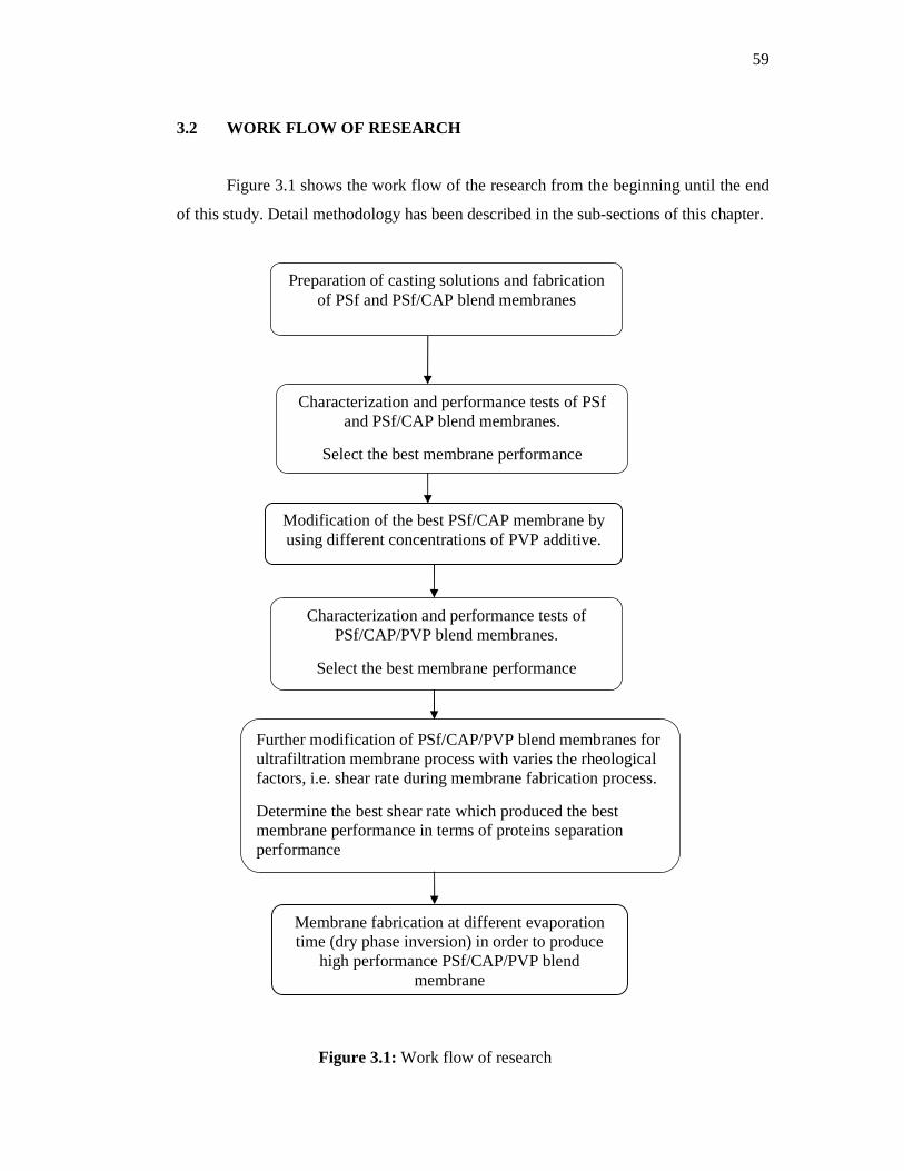
59
3.2 WORK FLOW OF RESEARCH
Figure 3.1 shows the work flow of the research from the beginning until the end
of this study. Detail methodology has been described in the sub-sections of this chapter.
Figure 3.1: Work flow of research
Modification of the best PSf/CAP membrane by using different concentrations of PVP additive.
Membrane fabrication at different evaporation time (dry phase inversion) in order to produce
high performance PSf/CAP/PVP blend membrane
Further modification of PSf/CAP/PVP blend membranes for ultrafiltration membrane process with varies the rheological factors, i.e. shear rate during membrane fabrication process.
Determine the best shear rate which produced the best membrane performance in terms of proteins separation performance
Characterization and performance tests of PSf and PSf/CAP blend membranes.
Select the best membrane performance
Preparation of casting solutions and fabrication of PSf and PSf/CAP blend membranes
Characterization and performance tests of PSf/CAP/PVP blend membranes.
Select the best membrane performance

60
3.3 MATERIALS
The basic formula to prepare and fabricate membrane consists of polymer and
solvent. This membrane casting solution is known as binary solution. If additive is
added into the binary solution, the membrane casting solution is known as ternary
solution. This ternary solution consists of three main components, namely polymer,
solvent and additive.
As mentioned in the scope of study in this thesis, polysulfone (PSf) was used as
the polymer backbone for ultrafiltration (UF) membrane and cellulose acetate phthalate
(CAP) was used as polymer blend material in order to improve hydrophilicity of the
native membrane property. N-methyl-2-pyrrolidone (NMP) was chosen as solvent in
binary solution and ternary solution of polymer casting solutions. An organic additive,
polyvinylpyrrolidone (PVP) was selected as an additive in order to improve
performance of blend UF membranes.
Distilled water was used as coagulation medium in a coagulation bath. It plays a
key role as non-solvent in precipitation process where the exchange between solvent
and non-solvent in polymer films formed asymmetric blend UF membranes via wet
phase inversion method. In pure water permeation test, distilled water was employed to
compact PSf, PSf/CAP and PSf/CAP/PVP blend UF membranes and to study the flux
of the pure water for each UF membranes at steady-state condition. Proteins with
different molecular weights were used in order to study permeation rate and proteins
rejection as well as molecular weight cut-off and pores properties of the blend UF
membranes.
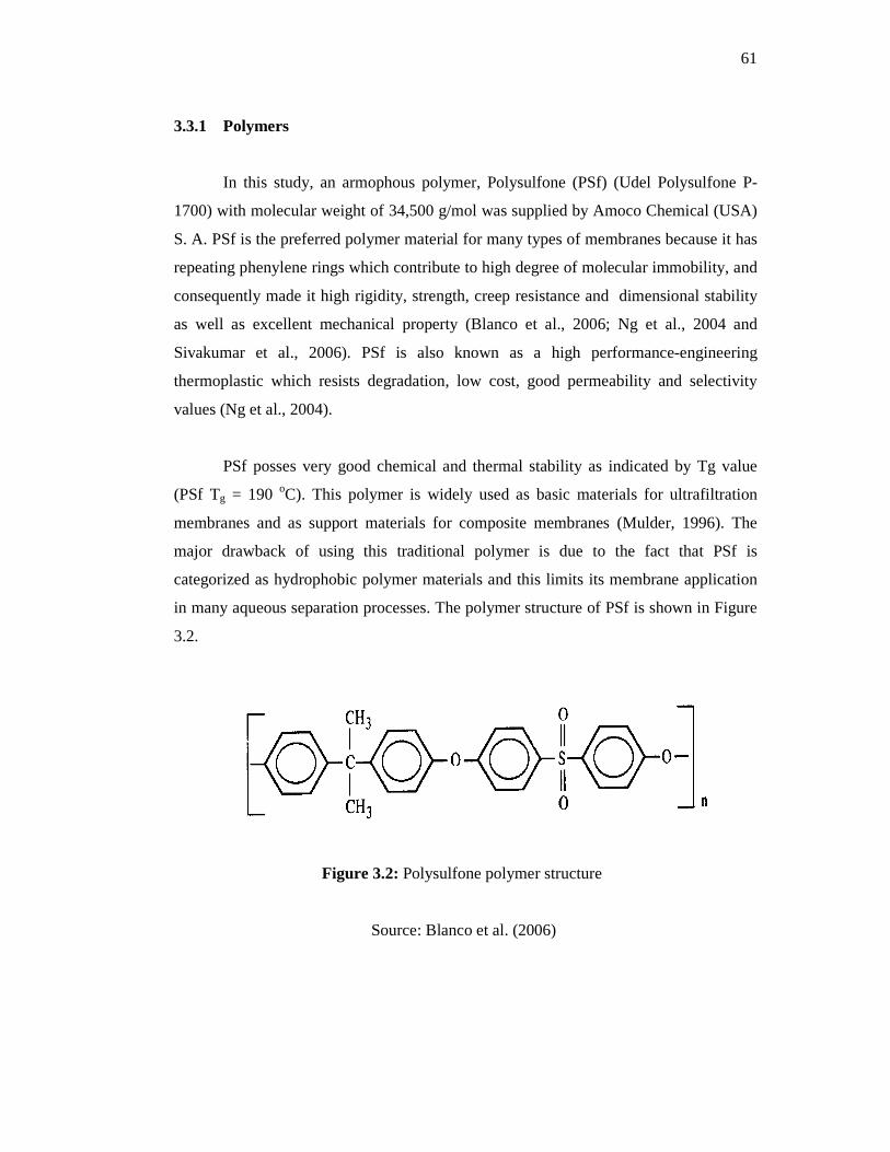
61
3.3.1 Polymers
In this study, an armophous polymer, Polysulfone (PSf) (Udel Polysulfone P-
1700) with molecular weight of 34,500 g/mol was supplied by Amoco Chemical (USA)
S. A. PSf is the preferred polymer material for many types of membranes because it has
repeating phenylene rings which contribute to high degree of molecular immobility, and
consequently made it high rigidity, strength, creep resistance and dimensional stability
as well as excellent mechanical property (Blanco et al., 2006; Ng et al., 2004 and
Sivakumar et al., 2006). PSf is also known as a high performance-engineering
thermoplastic which resists degradation, low cost, good permeability and selectivity
values (Ng et al., 2004).
PSf posses very good chemical and thermal stability as indicated by Tg value
(PSf Tg = 190 oC). This polymer is widely used as basic materials for ultrafiltration
membranes and as support materials for composite membranes (Mulder, 1996). The
major drawback of using this traditional polymer is due to the fact that PSf is
categorized as hydrophobic polymer materials and this limits its membrane application
in many aqueous separation processes. The polymer structure of PSf is shown in Figure
3.2.
Figure 3.2: Polysulfone polymer structure
Source: Blanco et al. (2006)

62
Cellulose acetate phthalate (CAP) brand Fluka was procured from Sigma-Adrich
Co. CAP is a white powder with molecular weight of 2,534.12 g/mol. This substance is
not classified as dangerous material, tasteless, light odor of acetic acid and low water
solubility (Bechard et al., 1995). It could be used as received without any purification.
In pharmaceuticals, CAP is one of the cellulose derivatives that have been commonly
used in controlled release drug delivery system as an enteric coating material (Reshmi et
al., 2009).
In this system, a polymeric oral tablet coating, CAP plays a role as a protection
material for drugs during its transit through the stomach and it will release the drugs
when it reaches the small intestine (Mayhew et al., 2009 and Oliviera et al., 2010). The
drugs are protected from dissolved in stomach due to the changes in pH environment.
This cellulose polymer commonly contains 21.5-26.0% (w/w) acetyl content and 30.0-
36.0% (w/w) phthalyl content according to USP specifications (Lai et al., 2008). Its
empirical formula is C116H116O64 and Figure 3.3 shows the polymer structure of CAP.
Figure 3.3: Polymer structure of cellulose acetate phthalate
Source: Rao et al. (1999)
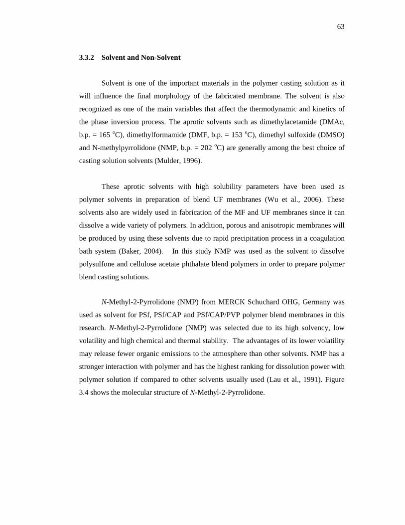
63
3.3.2 Solvent and Non-Solvent
Solvent is one of the important materials in the polymer casting solution as it
will influence the final morphology of the fabricated membrane. The solvent is also
recognized as one of the main variables that affect the thermodynamic and kinetics of
the phase inversion process. The aprotic solvents such as dimethylacetamide (DMAc,
b.p. = 165 oC), dimethylformamide (DMF, b.p. = 153 oC), dimethyl sulfoxide (DMSO)
and N-methylpyrrolidone (NMP, b.p. = 202 oC) are generally among the best choice of
casting solution solvents (Mulder, 1996).
These aprotic solvents with high solubility parameters have been used as
polymer solvents in preparation of blend UF membranes (Wu et al., 2006). These
solvents also are widely used in fabrication of the MF and UF membranes since it can
dissolve a wide variety of polymers. In addition, porous and anisotropic membranes will
be produced by using these solvents due to rapid precipitation process in a coagulation
bath system (Baker, 2004). In this study NMP was used as the solvent to dissolve
polysulfone and cellulose acetate phthalate blend polymers in order to prepare polymer
blend casting solutions.
N-Methyl-2-Pyrrolidone (NMP) from MERCK Schuchard OHG, Germany was
used as solvent for PSf, PSf/CAP and PSf/CAP/PVP polymer blend membranes in this
research. N-Methyl-2-Pyrrolidone (NMP) was selected due to its high solvency, low
volatility and high chemical and thermal stability. The advantages of its lower volatility
may release fewer organic emissions to the atmosphere than other solvents. NMP has a
stronger interaction with polymer and has the highest ranking for dissolution power with
polymer solution if compared to other solvents usually used (Lau et al., 1991). Figure
3.4 shows the molecular structure of N-Methyl-2-Pyrrolidone.
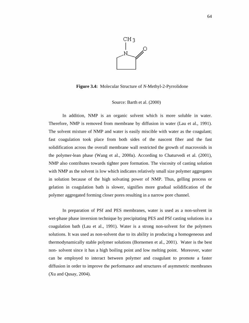
64
Figure 3.4: Molecular Structure of N-Methyl-2-Pyrrolidone
Source: Barth et al. (2000)
In addition, NMP is an organic solvent which is more soluble in water.
Therefore, NMP is removed from membrane by diffusion in water (Lau et al., 1991).
The solvent mixture of NMP and water is easily miscible with water as the coagulant;
fast coagulation took place from both sides of the nascent fiber and the fast
solidification across the overall membrane wall restricted the growth of macrovoids in
the polymer-lean phase (Wang et al., 2000a). According to Chaturvedi et al. (2001),
NMP also contributes towards tighter pore formation. The viscosity of casting solution
with NMP as the solvent is low which indicates relatively small size polymer aggregates
in solution because of the high solvating power of NMP. Thus, gelling process or
gelation in coagulation bath is slower, signifies more gradual solidification of the
polymer aggregated forming closer pores resulting in a narrow pore channel.
In preparation of PSf and PES membranes, water is used as a non-solvent in
wet-phase phase inversion technique by precipitating PES and PSf casting solutions in a
coagulation bath (Lau et al., 1991). Water is a strong non-solvent for the polymers
solutions. It was used as non-solvent due to its ability in producing a homogeneous and
thermodynamically stable polymer solutions (Bornemen et al., 2001). Water is the best
non- solvent since it has a high boiling point and low melting point. Moreover, water
can be employed to interact between polymer and coagulant to promote a faster
diffusion in order to improve the performance and structures of asymmetric membranes
(Xu and Qusay, 2004).

65
3.3.3 Additive
Generally, in order to improve membrane permeation rate, hydrophilic polymers
such as polyvinylpyrrolidone (PVP) and polyethylene glycol (PEG) are used as an
additive in polymer casting solutions. These polymers are recognized as the suitable
polymer additive to produce high performance membranes (Bowen et al., 2001). The
PVP additive is added to the mixture of base polymer and solvent in order to enhance
the phase inversion process. Many research studies have been conducted to investigate
the role of PVP additive on the membrane preparation process. The relationship
between PVP additive concentration on membrane performance and structural
properties has already been studied by Ismail and Hassan (2007).
Boom et al. (1992) investigated the effect of PVP on the formation of
membranes and found that addition of PVP to the ternary system suppresses the
formation of macrovoids in the sub-layer but Wang et al. (2009) reported that the
addition of PVP to PES membrane promoted formation of macrovoids as a result these
membranes had higher water flux, water absorption, and lower water contact angle (CA)
than the pure PES membrane. In this study, polyvinylpyrrolidone (PVP) K15 was used
in preparing PSf/CAP blend casting solutions. PVP K15 with molecular weight of
10 000 kDa was purchased from Fluka and directly used without any purification.
3.4 MEMBRANE PREPARATION
In this study, there are two types of polymer casting solutions were prepared, a
casting solutions containing PSf/CAP blend solution and the PSf/CAP/PVP casting
solutions containing an additive polymer, PVP. Table 3.1 shows the formulation of
PSf/CAP casting solutions and Table 3.2 tabulates the composition of the PSf/CAP/PVP
casting solutions that were prepared in this study. The materials used in preparing these
casting solutions were PSf and CAP as polymers, PVP as additive and NMP employed
as solvent. Firstly, polymers (PSf and CAP) were heated at about 60 oC for 24 hrs in
order to remove moisture content in a convective oven. The presence of the moisture in
polymers affected the quality and composition of polymer casting solutions which in
turn changed the casting solution properties.

66
After that, PSf polymer was added into a round bottom flask which contains
solvent, NMP that was heated by using a heating mantle. The mixture of polymer and
solvent heated up about 90 oC and stirred using WiseStirTM Digital Overhead Strirrer
supplied from DAIHAN Scientific, Co., Ltd. The casting solutions were stirred at 200
rpm in order to ensure the polymer and solvent were well mixed. Then, CAP polymer
was added when PSf polymer absolutely dissolved in the solvent. The casting solution
was kept stirred for 7 to 8 hrs to form a homogeneous PSf/CAP polymer casting
solution. Finally the prepared PSf/CAP blend casting solutions were placed in an
ultrasonic bath for about 3 hours to remove the trapped air bubbles.
Table 3.1: Formulation of PSf and PSf/CAP blend casting solutions
Membrane
Code
Polymer
composition (%)a Solvent (wt%)
PSf/CAP in
polymer
composition
(%)
PC PSf CAP NMP PSf/CAP
PC-0 17.00 0.00 83.00 100/0
PC-5 16.15 0.85 83.00 95/5
PC-10 15.30 1.70 83.00 90/10
PC-15 14.45 2.55 83.00 85/15
PC-20 13.60 3.40 83.00 80/20
aTotal polymer composition in casting solution is 17.00 wt%

67
Table 3.2: Formulation of PSf/CAP/PVP blend casting solutions
Membrane
Code
Polymer composition
(%)a
Additive
(wt%)
Solvent
(wt%)
PCV PSf CAP PVP NMP
PCV-1 15.3 1.7 1.0 82.0
PCV-2 15.3 1.7 2.0 81.0
PCV-3 15.3 1.7 3.0 80.0
PCV-4 15.3 1.7 4.0 79.0
PCV-5 15.3 1.7 5.0 78.0
aTotal polymer composition in casting solution is 17.0 wt% with PSf/CAP polymer composition of 90/10
For the preparation of PSf/CAP/PVP casting solutions, after all polymers (PSf
and CAP) were dissolved then the PVP additive was added into the solutions and left
for about 8 hrs to ensure the dissolution process completed. After the casting solution
was homogenously dissolved, it was poured into a bottle and degassed for about 3 hrs
using an ultrasonic bath to remove any trapped micro-bubbles of gases prior to a casting
process. Finally, the PSf/CAP/PVP blend casting solutions was kept at room
temperature for membrane fabrication process. The apparatus for preparing the polymer
casting solutions is shown in Figure 3.5.

68
Figure 3.5: Schematic diagram of apparatus used for preparation of polymer casting solution
3.5 MEMBRANE SYNTHESIS
A flat sheet of PSf/CAP and PSf/CAP/PVP blend membrane was prepared via a
simple wet phase inversion process. A high precision casting machine supplied by Kras
Instrument & Services (Malaysia) was used to fabricate the membrane as shown in
Figure 3.6. Firstly, a casting solution poured on a clean stainless steel plate at room
temperature. The stainless steel plate moved at certain velocity (shear rate) towards a
casting knife and then, the dope solution was cast by the casting knife with a thickness
of about 200 µm.
Immediately after the casting process finished, the plate with the cast film was
immersed into a coagulation bath which contains tap water as coagulation medium.
After a few minutes, a thin polymeric film formed and separated out from the stainless
steel plate due to the wet-phase inversion process. After the precipitation process was
completed, the membrane was washed with distilled water and dipped in a container
Condenser
Flange ReactionFlask
Heating Unit
Stirrer
Feed Funnel
Thermometer
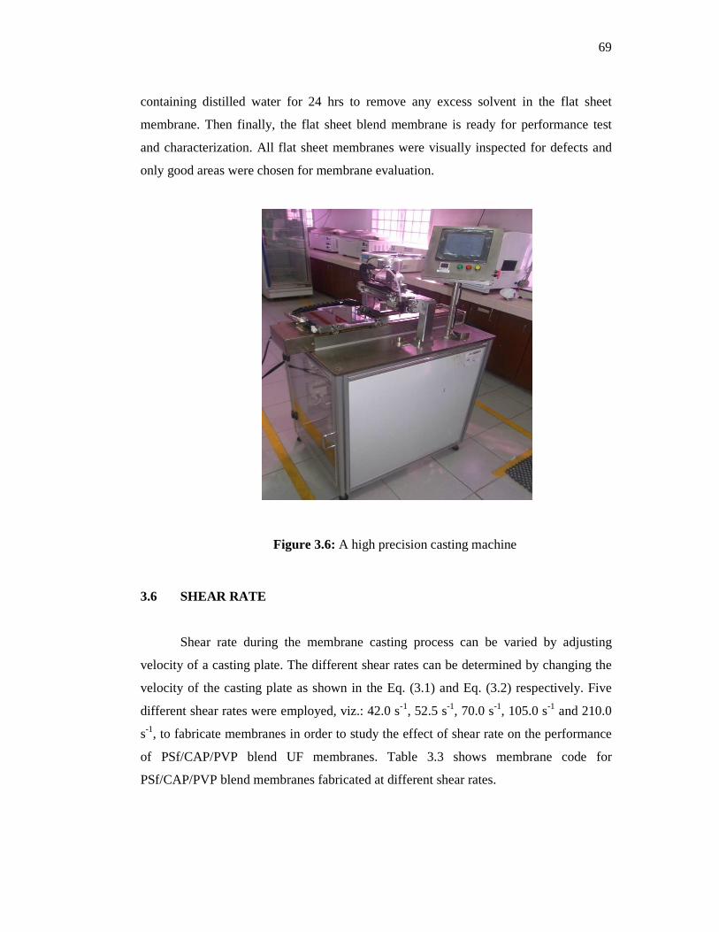
69
containing distilled water for 24 hrs to remove any excess solvent in the flat sheet
membrane. Then finally, the flat sheet blend membrane is ready for performance test
and characterization. All flat sheet membranes were visually inspected for defects and
only good areas were chosen for membrane evaluation.
Figure 3.6: A high precision casting machine
3.6 SHEAR RATE
Shear rate during the membrane casting process can be varied by adjusting
velocity of a casting plate. The different shear rates can be determined by changing the
velocity of the casting plate as shown in the Eq. (3.1) and Eq. (3.2) respectively. Five
different shear rates were employed, viz.: 42.0 s-1, 52.5 s-1, 70.0 s-1, 105.0 s-1 and 210.0
s-1, to fabricate membranes in order to study the effect of shear rate on the performance
of PSf/CAP/PVP blend UF membranes. Table 3.3 shows membrane code for
PSf/CAP/PVP blend membranes fabricated at different shear rates.

70
V������� � ����� ���� (����) = �������� ������ (�)
�!�"�� #���� !#��$ (!) (3.1)
%ℎ�' '�� (���) = (��)*"�+ ), *�!�"�� #���� (�!-.)
�������� ��"*/��!! (�) (3.2)
Table 3.3: Membrane code for PSf/CAP/PVP blend membranes fabricated at different shear rates
Shear rate
(s-1)
Membrane
Code
42.0
52.5
70.0
105.0
210.0
PCS-1
PCS-2
PCS-3
PCS-4
PCS-5
3.7 EVAPORATION TIME
In order to optimize the membrane separation performance, dry-phase
inversion method was introduced before wet-phase inversion process took place during
preparation of PSf/CAP/PVP blend membrane. In the dry phase inversion method, the
cast polymer solution was introduced with a convective inert stream (nitrogen) for a
certain period of time which is known as evaporation time. During this evaporation
time, the convective stream removed the most volatile solvent from membrane surface,
which results in a region with locally elevated polymer concentration at the nascent
membrane surface. The complete phase inversion process was followed by wet-phase
inversion method. In this study, the effect of evaporation time on membrane
characteristics and separation performances in the range of 5, 10, 15 and 20 s were
studied. Table 3.4 shows membrane code for PSf/CAP/PVP blend membranes
fabricated at different evaporation time.

71
Table 3.4: Membrane code for PSf/CAP/PVP blend membranes fabricated at different evaporation time
Evaporation Time
(s)
Membrane
Code
5
10
15
20
25
PCE-5
PCE-10
PCE-15
PCE-20
PCE-25
3.8 MEMBRANE PERFORMANCE TESTS
The performance of PSf/CAP and PSf/CAP/PVP blend membranes were tested
in terms of pure water flux, permeate flux and solute rejection. These testing were
carried out using a Sterlitech HP4750 Stirred Cell supplied by Sterlitech as shown in
Figure 3.7. Ultrafiltration membrane process was operated in the dead-end filtration cell
with volume capacity of 300 ml and an active area of 14.6 cm2. The Sterlitech HP4750
Stirred Cell is a chemical resistant cell with a maximum pressure rating of 69 bar (1000
psig). This cell is also suited to perform microfiltration (MF), nanofiltration (NF) and
reverse osmosis (RO) separation.
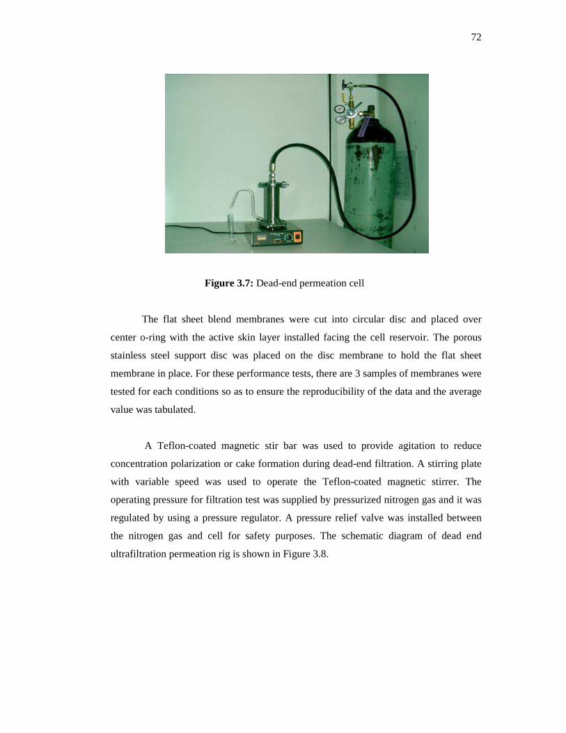
72
Figure 3.7: Dead-end permeation cell
The flat sheet blend membranes were cut into circular disc and placed over
center o-ring with the active skin layer installed facing the cell reservoir. The porous
stainless steel support disc was placed on the disc membrane to hold the flat sheet
membrane in place. For these performance tests, there are 3 samples of membranes were
tested for each conditions so as to ensure the reproducibility of the data and the average
value was tabulated.
A Teflon-coated magnetic stir bar was used to provide agitation to reduce
concentration polarization or cake formation during dead-end filtration. A stirring plate
with variable speed was used to operate the Teflon-coated magnetic stirrer. The
operating pressure for filtration test was supplied by pressurized nitrogen gas and it was
regulated by using a pressure regulator. A pressure relief valve was installed between
the nitrogen gas and cell for safety purposes. The schematic diagram of dead end
ultrafiltration permeation rig is shown in Figure 3.8.
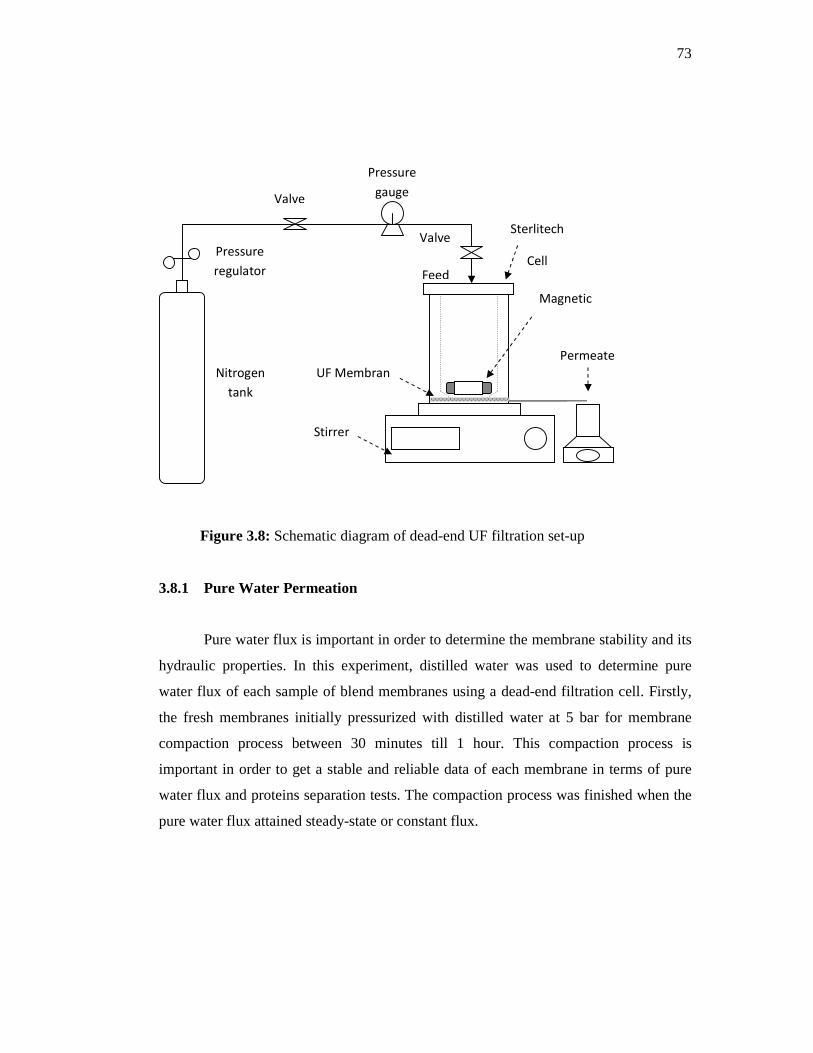
73
Figure 3.8: Schematic diagram of dead-end UF filtration set-up
3.8.1 Pure Water Permeation
Pure water flux is important in order to determine the membrane stability and its
hydraulic properties. In this experiment, distilled water was used to determine pure
water flux of each sample of blend membranes using a dead-end filtration cell. Firstly,
the fresh membranes initially pressurized with distilled water at 5 bar for membrane
compaction process between 30 minutes till 1 hour. This compaction process is
important in order to get a stable and reliable data of each membrane in terms of pure
water flux and proteins separation tests. The compaction process was finished when the
pure water flux attained steady-state or constant flux.
Sterlitech
Cell Pressure
regulator
Valve
Nitrogen
tank
Pressure
gauge
Valve
UF Membran
Feed
Permeate
Magnetic
Bar
x
Stirrer
Machine

74
Then, membranes were subjected to pure water flux test with varying operating
pressure in the range 1 to 5 bar. The pure water flux was measured at steady-state
conditions and it can be calculated by Eq. (3.3).
txA
VJv ∆
= (3.3)
where;
Jv = the permeate flux or water flux (l/m2 h)
A = the effective area of membrane (m2),
∆t = sampling time (h)
V = Volume of permeate solution collected, (l)
In the pure water flux test, the permeability of each membrane was determined
by the measurement of water permeability as a function of applied pressure. It was
evaluated from the slope figure of pure water flux versus operating pressure.
P
JP v
m ∆= (3.4)
where;
Pm = Membrane permeability (l/m2 h.bar),
Jv = Flux (l/m2 h)
�P = Pressure (bar)
Membrane hydraulic resistance, 0� (m2h.bar/l) can be calculated from the
inverse of the membrane permeability and the calculated equation as shown as below:
0� = ∆2
34 (3.5)

75
3.8.2 Protein Separation Performance
Different molecular weight of proteins was used to study membrane separation
performance and to determine molecular weight cut-off (MWCO) of each membrane.
Four different molecular weight of proteins were used in this separation such as trypsin
(23 kDa), pepsin (35 kDa), egg albumin, EA (44.3 kDa) and bovine serum albumin,
BSA (66 kDa). Trypsin, pepsin and EA were supplied by Sigma-Aldrich, and BSA was
procured from Fluka, USA. All the proteins were used as received.
Pottasium dihydrogen phosphate (KH2PO4) with molecular weight of 136.08
g/mol and di-Pottasium hydrogen phosphate (K2HPO4) with molecular weight of 174.18
g/mol were obtained from Merck and used for preparation of phosphate buffer solution
in protein analysis. Distilled water was used as a solvent agent in preparing phosphate
buffer solution. For protein permeation, a single solution of protein was prepared at
concentration of 500 ppm by dissolving a pre-weighed protein powder in phosphate
buffer of 7.2 pH. Protein solution was prepared no longer than one hour before used and
was stored at 4 oC to ensure protein molecules were active and had no bacterial
contamination.
The protein separation for the low molecular weight was first done following the
consequent increasing molecular weight of proteins. The separation was performed in
the order of trypsin (23 kDa), pepsin (35 kDa), EA (44.3 kDa) and BSA (66 kDa) to
avoid the hindrance effect of the bigger proteins on the active surface of the membrane
if the protein separation performed first by the separation of a high molecular weight of
proteins followed by the separation of low molecular weight of proteins
(Arthanareeswaran et al., 2007c)
For the protein separation study, protein solution was filled in the dead-end cell
with an effective permeation area of 14.6 cm2. The protein solution was pressurized at a
constant pressure of 3 bar and the volume of permeate solution of the corresponding
membranes was measured and collected in a graduated glass cylinder. The protein
solutions were stirred homogenously at 100 rpm to avoid concentration polarization and
fouling of proteins. The absorbance of feed and permeate of proteins were analyzed by
76
UV-Vis spectrophotometer (Hitachi U-2000) at wavelength of 280nm. From the feed
and permeate concentrations, the percentage rejection was calculated using Eq. 2.12.
The average data of three replicates were reported.
Finally, after each protein separation process finished, the cell was emptied and
filled with distilled water and then, stirred at 400 rpm for 30 minutes in order to remove
any adhered protein on the membrane surface. The membrane was removed and washed
gently many times with distilled water and then placed in the dead-end cell for the next
protein separation.
3.9 MEMBRANE CHARACTERIZATION
3.9.1 Water Content
The water content of the PSf/CAP and PSf/CAP/PVP blend membranes were
evaluated by their capacity for water absorption and calculated by Eq. (3.6) :
5 = 6789�6:;<
6789× 100% (3.6)
where
A = the water content (wt%),
Wwet = the wet weight of membrane (mg)
Wdry = the dry weight of membrane (mg)
The water content of the membranes was determined by soaking the membranes
in water for 24 h at room temperature. The weights of the wet blend membranes were
first measured after mopping the membranes with blotting paper, and then the
membranes were dried in oven at 75 oC for 48 h (Sivakumar, et al., 2006). The weights
of the dry blend membranes were measured again after it cooled. At least three
measurements of water content were measured and the results were averaged to get a
reliable value.

77
3.9.2 Porosity
The porosity of blend membranes were evaluated by their capacity of water
absorption and calculated using the expression below (Machado, et al., 2006):
A�'����� =B6.-CD $7E98;⁄ G
(× 100% (3.7)
where
W1 and W2 = the mass of membrane in the wet and dry states (mg)
dwater = the density of water at room temperature (ml/mg)
V = the volume of the membrane in the wet state (ml)
3.9.3 Contact Angle
The measurement of hydrophlicity of blend membranes via contact angle
measurement was done at Malaysian Nuclear Agency (MINT) in Bangi, Sedang,
Selangor. Contact angles of the dry membranes were measured using a FACE Contact
Angle Meter, model CA-A. (FACE Kyowa Kaimenkagaku Co. LTD). A droplet of
ultrapure water was delivered onto the dry membrane surface and a static image of the
droplet was taken immediately after contact with the membrane surface. The contact
angles measurement were performed three times for each sample and the average
measurement was reported.
3.9.4 Scanning Electron Microscopy (SEM)
The Scanning Electron Microscopy (SEM) (JSM P/N HP475 model) at Institute
of Oceanography, Universiti Malaysia Terengganu (UMT) was used to analyze
morphological structures of blend membranes as shown in Figure 3.9. The membrane
morphology is one of the basic requirements to understand and explain relation between
morphology of membranes and the performance of the membranes.

78
Membranes were cut into small specimens and immersed into liquid nitrogen in
a small container. The membranes were fractured after immersion and the fractured
membranes were then placed in an automatic coater (JFC 1600 model) to coat the
membrane samples. The samples were coated with a thin gold layer for 30 minutes to
prevent charging up of the membrane surface by electron beam which in turn damaged
or burned the samples. Cross sections of the flat sheet blend UF membranes were
obtained after coating process using SEM equipment.
Figure 3.9: A full set of scanning electron microscope (SEM)
Electron emission
SEM
Control
panel
Monitor

79
3.9.5 Molecular Weight Cut-off and Pore Properties
Molecular Weight Cut-off (MWCO)
Molecular Weight Cut-off (MWCO) of the PSf/CAP and PSf/CAP/PVP blend
membranes were determined by the rejection studies of different molecular weights of
proteins such as trypsin (23 kDa), pepsin (35 kDa), egg albumin, EA (44.3 kDa) and
bovine serum albumin, BSA (66 kDa) in an ultrafiltration cell filter (Arthanareeswaran,
et al., 2010 and Sivakumar, et al., 2006). In this study, MWCO of the blend membranes
were obtained based on the lowest molecular weight of protein that was rejected at 80%
in the figure of protein rejection versus molecular weights of protein. The calculation of
the solute rejection is presented by Eq. (2.12).
Pore Properties
Pore properties of the surface of blend membranes was determined in terms of
the average pore size and pore density. As MWCO of blend membranes were
determined, the average pore size of blend membranes can be obtained by using Figure
2.9. The results of the ultrafiltration of different molecular weights protein solutions
were used to calculate the pore density of the membranes from Eq. (2.14) to Eq. (2.15)
as explained by Sarbolouki (1982).