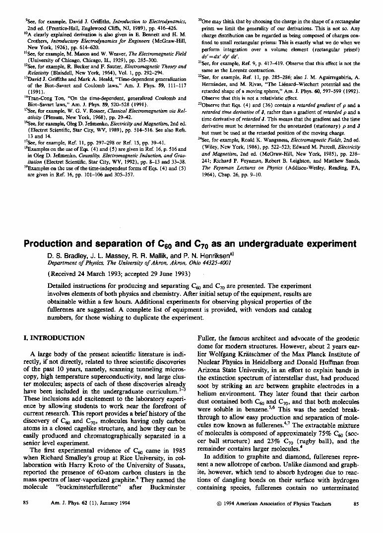
synthesis of gram quantities of cc0 by plasma discharge in ... · round-bottomed flask that has had...
TRANSCRIPT

6932 J. Org. Chem. 1992,57,6932-6936
Synthesis of Gram Quantities of Cc0 by Plasma Discharge in a Modified Round-Bottomed Flask. Key Parameters for Yield Optimization and
Purification
Walter A. Scrivens and James M. Tour* Department of Chemietry and Biochemistry, University of South Carolina, Columbia, South Carolina 29208
Received September 11,1992
Described is the fabrication of a plasma discharge reactor constructed from a l-L round-bottomed flask that allows for the preparation of gram quantities of Cm in an &h period. The modified reactor design (1) is inexpensive, (2) requires almost no machining, (3) has high thru-put, (4) affords high yields of fullerenes, (5) allows one to have near-continuous feed of graphite rods, and (6) permits control over four major reaction pametera important for the clean formation of fullerenes. The four major reaction parameters nece%sary to control for the high yield of fullerenes are the absolute pressure, the rate of helium gas flow through the reactor, the current level of the arc as determined by the setting on the arc welding unit, and the arc gap maintained by monitoring the current on a clip-on digital AC current meter. Since the apparatus described can allow for easy adjustment of all four major reaction parameters, this design could also be used to study the changes in fulleroid content based on parameter modification. Ale0 detailed is the efficacy of a procedure for the purification of the crude fullerene mixtures using activated charcoal as a chromatographic stationary phase.
Since the initial discovery of buckminsterfullerene (Cd in 1985l and the subsequent development of the carbon arc method for producing macroscopic quantities of this material? a large amount of effort has been directed to- ward the understanding and utilization of this new allo- trope of carbone3 We describe here the fabrication of a plasma discharge reactor constructed from a l-L round- bottomed flask that allows for the preparation of gram quantities of CW in an &h period. The reactor design (1) is inexpensive, (2) requires h o s t no machining, (3) allows high thru-put, (4) affords high yields of fullerenes, (5) allows one to have near continuous feed of graphite rods, and (6) permits control over four major reaction parame- ters important to the clean formation of fullerenes. Since the apparatus described can allow for easy adjustment of all four major reaction parameters, this deaign could also be used to study the changes in fulleroid content based on parameter modification. We also detail the efficacy of a procedure for the purification of the crude fullerene mixtures using activated charcoal as a charomatographic stationary phase.
The most common method of producing CW utilizea the Huffman-Krlltschmer carbon arc method in which gra- phite electrodes are vaporized in a low presaure helium atmosphere by passing an electrical current through the electrodes, thus generating an arc. The soot produced by this carbon arc contains CW as well as some other higher molecular weight fullerenes. A number of reporta on this method have appeared that provide details of the apparati used.41s There are two major varianta of the carbon arc
(1) Kroto, H. W.; Heath, J. R.; OBrien, S. C.; Curl, R. F.; Smalley, R. E. Nature 1986.318. 162.
(2) Kriitschlder, W.; Lamb, L. D.; Fostiropoulos, K.; Huffman, D. R. Nature 1990,347, 364.
(3) For recent review on CBo, see: (a) McLafferty, F. W., Ed. Acc. Chem. Res. 1992,25,97. (b) Kroto, H. W. Angew. Chem., Znt. Ed. Engl. 1992,31,111. (c) Diederich, F.; Whetten, R. L. Angew. Chem., Int. Ed. Engl. 1991,30,678. (d) Kroto, H. W.; Allaf, A. W.; Balm, S. P. Chem. Rev. 1991,91,1213. (e) Stoddnrt, J. F. Angew. Chem., Znt. Ed. Engl. 1991, 30,70. Also see: (f) Fullerenes; Hammond, G. S.; Kuck, V. J.; Ede.; ACS Symp. Ser., 481; American Chemical Society: Washington, DC, 1992.
(4) (a) Parker, D. H.; Wun, P.; Chatterjee, K.; Lykke, K. R.; Hunt, J. E.; Pellin, M. J.; Hemminger, J. C.; Gruen, D. M.; Stock, L. M. J. Am. Chem. Soc. 1991,113,7499. (b) Koch, A. S.; Khemani, K. C.; Wudl, F. J. Org. Chem. 1991,56,4643. (c) Pradeep, T.; Rao, C. N. R. Mat. Res. Bull. 1991,26,1101. (d) Hare, J. P.; Kroto, H. W.; Taylor, R. Chem. Phys. Lett. 1991,177,394. (e) Hautler, R. E.; Conceicno, J.; Chibante, L. P. F.; Chai, Y.; Byme, N. E.; Flanagan, S.; Haley, M. M.; O'Brien, 5. C.; Pan, C.; Xiao, Z.; Billups, W. E.; Ciufolini, M. A.; Hauge, R. H.; Margrave, J. L.; Wilson, L. J.; Curl, R. F.; S d e y , R. E. J. Phys. Chem. 1990,94,8634.
0022-326319211957-6932$03.00/0
method, namely, contact arc and plasma discharge. In the contact arc method, the graphite electrodes are kept in constant contact through either a gravity feed mechanism4b or through the use of a feed spring."Ie To date, the most easily accessible apparatus for the contact arc method is the gravity feed apparatus developed by W ~ d l . ~ ~ This is a relatively inexpensive and simple device which uses an arc welder as the power source. However, like all other contact arc apparati, it suffers from overheating problems due to resistive heating of the graphite electrodes and the apparatus must be disassembled for the insertion of new graphite rods. The plasma discharge methodhd maintains a constant arc gap between the electrodes, thus avoiding much of the resistive heating problems found in the con- tact arc methods. This method can potentially produce crude fullerenes more efficiently by providing more control over the conditions which form the fullerenes in the re- actor. The drawback to the plasma discharge method is that it requires a fairly complex apparatus with special feed mechanisms to align the electrodes and maintain a con- stant arc gap. And, like most other methods, the apparatus must be disassembled for the insertion of new graphite rods.
Here we describe the simple fabrication and use of a low cost fullerene generator of the plasma discharge type (Figure 1). The reaction vessel is simply a l-L Pyrex round-bottomed flask that has had an additional 24/40 female joint affixed opposite to the first joint. The Pyrex guide arms (12 mm 0.d.) extend from outside the water cooling bucket and are fitted with vacuum take off adap- ters and tipped with 24/40 male joints that insert into the reactor vessel (the total length of the guide arm including the male joint ie 25 cm). The guide arms help to align the l-cm-diameter copper mounting rods (each copper mounting rod is 35 cm long). One end of the copper mounting rods has a 3/16 in. diameter hole drilled to a l-cm depth for mounting the graphite electrodes and on the other end has a screw hole tapped so that the rods can be attached to the arc welder with brass screws. The copper mounting rods extend out through the end of the guide arms and through standard 19/22 septa which have
(5) There are other methods of producing CW, most notably from hydrocarbon h e s and by the thermal evaporation of carbon, see: (a) Howard, J. B.; McKinnon, J. T.; Makarowky, Y.; Laflew, A. L.; J o h n , M. E. Nature 1991,352,139. (b) Peters, G.; Jansen, M. Angew. Chem., Znt. Ed. Engl. 1992, 31, 223.
@ 1992 American Chemical Society

Gram Quantities of CSO by Plasma Discharge J. Org. Chem., VoZ. 57, No. 25, 1992 6933
SCALE: - - S u n
Figure 1.
a no. 2 hole punched through their center. These septa maintain a seal between the sliding copper mounting rod and the end of the Pyrex guide arm. The guide arm’s vacuum take off adapters connect, via rubber tubing, to a gas manifold mounted above the reactor vessel (the outside diameter of the manifold tubing is 15 mm).
The entire vessel, except for the ends of the guide arms, is submerged in a cooling water bath made from a plastic storage container.6 Two holes slightly less than 25 mm in diameter are made in the side of the storage container by heating an appropriately-sized glass tube in a gas flame and melting through the plastic. It is through these holes that the guide arms pass while water leaks are prevented by using rubber gaskets made from a short lengths of 25” rubber tubing. A submersible water pump is placed at the bottom of the cooling bath which helps to circulate the cooling (tap) water around the vessel and allows the
(6) These storage containers are available at most department stores for approximately $10 and are made of a flexible plastic similar to plastic garbage containers.
, 220V/SOA I
water to be removed from the bath as quickly as it flows in from a rubber hose at the top of the bath. If the water is not circulated and replenished in this manner, the bath tends to overheat, which can result in the vessel cracking.
The gas manifold above the vessel carefully monitors and controls the atmospheric conditions inside the vessel. Helium flows into the left side of the manifold and the gas is removed from the right sie of the manifold by a vacuum pump. The absolute pressure of gas in the vessel is monitored by a mercury manometer mounted on the right side of the manifold just above the reactor vessel. The pressure difference between the two sides of the vessel is an indication of the direction and magnitude of gas flow through the vessel and is measured by a silicon oil ma- nometer (8 mm 0.d.) mounted across the two sides of the manifold. The flow of the gas through the reaction vessel is controlled by two standard high vacuum Teflon-brand plug control valves. The central valve acts as a shunt, directing all or some of the helium flow through the vessel rather than across the top of the manifold. The valve on

6934 J. Org. Chem., Vol. 57, No. 25, 1992
5 -
4 -
3 -
2-
Yield vs He Pressure 8 .
Scrivem and Tour
Yield VI He Flow
0 5 E 3
1 : . , . , . , , I 0 200 400 800 800
h Prouuro (mm Ha)
Yield VI Welder Current
7w 0 F 3
Woldor Current (omperor)
Figure 2.
the right side of the manifold controls the rate of helium flow out of the vessel and thus regulates the sensitivity of the shunt control valve.
The reactor is powered by a variable current AC/DC arc welder which is plugged into a standard 220 V/50 A wall outlet.' A clip-on digital AC current meter is attached to the input end of the arc welder to monitor the current?
The apparatus described not only provides us with an inexpensive and easily fabricated fullerene reactor but also gives us the flexibility to adjust and optimize various re- action parameters in order to increase yields. We have determined that there are four easily adjusted parameters that must be maintained for high yields: (1) the absolute pressure, (2) the rate of helium gas flow through the re- actor, (3) the current level of the arc as determined by the setting on the arc welding unit, and (4) the arc gap maintained by monitoring the current on the clipon digital AC current meter. Other workers have dealt with some of these parameters but here we describe the control and optimization of all four parameters simultaneously (Figure 2). Optimization studies were done with inexpensive graphite welding electrodes? We eventually started using
(7) The arc welder (Lincoln Electric model AC/DC 225/125) was purchased from a local welding supplier and coat approximately $300.
(8) The clip-on digital AC current meter was purchased from a local electronics distributor for approximately $100. The meter is attached around one of the two hot lead of the 220 V power cord attached to the arc welder. One can access these leads by carefully removing the outer power cord covering, exposing three wires, namely, the two colored hot lends and the one white ground lead. Care must be taken to not penetrate the insulation of these inner wires. The current meter is then clipped around one of the e x p o d hot leads. The metallic portion of the wires should never be exposed. (9) Standard 3/16 in. copper-clad graphite electrodes (Arcair brand,
$O0.2S/rod) were obtained from a local weldw supply center. The copper sheathing was peeled off before use. Technical data sheets on thew electrodes showed that a significant amount of the mase consisted of nongraphitic binders that probably caused the lower yields seen in the optimization study graphs.
3 4 5 i Ho Flow (mm oil dilkrontial proaruro)
Yield vs Arc Gap
I
4 .
3 -
2 .
17 18 19 Arc Gap (ampwoo)
high purity graphite electrodes which doubled our yields.l0 Even with this change in electrode type, all the optimized reactor conditions given in Figure 2 hold for both sources of graphite except for the optimal arc gap measured in amperes on the clip-on digital AC current meter.
Helium pressure is the operating parameter that is commonly reported for the synthesis of fullerenes. Our studies have shown that there is a local yield maximum at about 150 " H g but that the yield optimum occurs at 450 mmHg after going through a yield minimum at 250 mmHg. An optimized operating pressure of 450 mmHg is significantly higher than the operating pressures of 100-200 " H g normally used by other ~o rke r s ;~ however, a recent report suggested that optimal pressures for gra- phitic nanotube formation was in the range of 500 mmHg, similar to our maximum for Cm formation." These pressures are monitored by a standard U-shaped mercury manometer and the pressures can be accurately adjusting by the low-pressure valve on the helium regulator.
The next condition that we investigated was that of helium flow through the reactor. By adjusting the flow control valves on the gas manifold and monitoring the differential pressure on the U-shaped silicon oil manom- eter, one can adjust the helium flow through the reactor from 0 mm (a static helium atmosphere) to greater than 30 mm oil pressure. A differential oil pressure reflects a net helium flow through the reactor from left to right. An optimum flow was found at 5 mm oil pressure. Pressures greater than 6 mm caused the soot to accumulate on the right side of the reactor and blew soot out of the reactor and into the manifold and vacuum lines. Pressures less than 4 mm gave extremely low yields and caused the soot
(10) Hkh q e t y graphite electrodes (Cat. #AXF-@l, $1.92/rod, 6 in. long, 3/16 in. b e t e r ) were obtained from Poco Graphite, Inc., 1601 South State Street, Decatur, TX 76234.
(11) E b h e n , T. W.; Ajayan, M. Nature 1992,358, 220.

Gram Quantities of C60 by Plasma Discharge
to accumulate on the left side of the reactor. Observation of the arc through a modified reactor vessel equipped with a view port12 revealed that under a static helium atmo- sphere the arc plume actually flowed from the poeitive to the negative electrode (this is the direction of the current flow). A slight helium flow in the opposite direction seemed to counteract this current flow and 'balanced" the arc so that at the optimum flow of 5 mm, the soot stayed in the center of the reactor vessel rather than flowing out one side or the other.
The welder current was the next parameter that we investigated and it was adjusted to obtain an optimum fullerene yield. Our studies showed that a current of 55 A gave the best yields. Higher current increased graphite rod burn rates but decreased yields.13 At currents lower than 55 A we had difficulty maintaining an arc.
Finally, varying arc gaps were investigated. Other workers optimized this parameter by setting the arc gap to a level where the arc was "brighte~t".~~ We sought to find a more objective criteria for determining arc gap and found that monitoring the current draw of the arc with the clipon digital AC current meter attached to the arc welder was a convenient and reliable way of monitoring this pa- rametera8 While using welding grade graphite rods? an optimum arc gap of 2-4 mm (determined visually through the view port)12 corresponded to a current reading of 18.5-19.0 A on the clip-on digital current meter. Using high purity graphite rods,1° the optimum arc gap of 2-4 mm corresponded to a current reading of 6.67.2 A on the clip-on digital current meter.
A detailed experimental procedure is as follows. The two guide arms were removed from a 110 OC oven, the 25-mm rubber tubing gaskets were slipped onto the end of the arms, the manifold hoees were attached, and the two arm assemblies were inserted through the holes of the empty cooling bath. The reactor vessel was then removed from the oven, the two joints are well-lubricated with silicon grease, and the vessel was mounted between the two guide arms. Adjustments in the guide arms were made to ensure a tight fit between the ground glass joints. Two weighed high purity graphite electrodeslO (6 in. long) were inserted into the ends of the two copper mounting rods, the rubber septa were slipped over the other ends of the rods, and the rod assemblies were then inserted into the end of the guide arms. The septa were adjusted so that they slip over the end of the guide arm and give a rea- sonable vacuum d . l S The chamber was then evacuated, and the reactor was attached to the arc welder with the screw connections. The cooling bath was filled with tap water and the water flow was adjusted so that when the submersible pump was turned on, there was no net flow of water out of the cooling bath. It is important that the reactor vessel is always covered with water to avoid cracking of the reactor. The system was then kept under
J. Org. Chem., Vol. 57, No. 25, 1992 6936
5 mm vacuum15 for 20 min. Helium was then introduced into the reactor and the pressure was adjusted at the regulator until an absolute pressure of 450 mmHg was obtained as determined by the mercury manometer. The flow control valves were then adjusted until a diffrential pressure of 5 mm was reached in the silicon oil U-tube. The copper mounting rods were pushed in until the two graphite rods were centered in the vessel but were not touching. While wearing rubber gloves and welder's gog- gles, the arc welder was set to 55 A DC, and the AC current meter and the arc welder were turned on (CAUTION).16 The right copper mounting rod was pushed in slightly so that the graphite electrodee brietly touched and established an arc. This right copper rod was then moved in or out until the current meter read 7.2 A. The rod was allowed to burn until the current meter read 6.6 A at which point the right copper rod was again pushed in until a 7.2-A reading was obtained. This process was then repeated. One only ne& to adjust the right copper rod (the poeitive electrode) because the left electrode is never consumed. It takes from %3 min for the graphite rod to burn through the 7.2-6.6-A range. Slag (as observed through the view port of our test apparatus)12 accumulates on the left electrode and must occasionally (about every 30 min) be removed. This is accomplished by turning off the arc welder, waiting 30 s for the electrodes to cool, and tapping on the left copper mounting rod with a glass rod which knocks the slag off the electrode. Failure to turn off the arc welder and wait for the electrodes to briefly cool before dislodging the slag can cause the vessel to crack when the hot slag hits the bottom of the vessel and induces thermal stresses in the glass. An entire 15-cm electrode was con- sumed in about 1.25 h. One must be careful to not burn the graphite rod down below 1.5 cm; failure to do this can cause the arc to jump to the copper mounting rod, melting the top of the copper rod and necessitating redrilling of the graphite rod holding hole. Additional graphite elec- trodes can be burned in the same run by turning off the welder, bringing the reactor up to atmospheric pressure, removing the right mounting rod and replacing the con- sumed graphite stub with a new rod, re-inserting the mounting rod, pumping the system down to 5 mmHg, bringing the atmosphere back to 450 mmHg, turning the welder back on, and initiating a new arc. One need not disassemble the apparatus nor empty the cooling bath during this procedure. About six rods can be consumed in an 8-h period. If more than eight rods are consumed in a single run, the guide arms tend to clog with soot and the reactor becomes inefficient.
When the run was complete, the reactor was taken apart and the vessel had the joints wiped free of grease with paper towels and hexane. One end of the vessel was c a p ped with a 24/40 rubber septum, the h k was filled with 500 mL of toluene, and then the other end of the vessel was also capped with a 24/40 rubber septum which had a needle inserted in it to avoid pressure build-up in the vessel. The reaction vessel was then carefully shaken to dislodge most of the soot and facilitate suspension of the soot in the toluene. The vessel was then placed in a sonic water bath for 30 min (with the needle pointing up and out of the water). The black soot suspension was then filtered through a pad of Celite-521 in a fritted glass funnel to give a dark red-brown solution of crude fullerenes. The
(12) The apparatus with a view port had an additional 24/40 female joint placed at right angles to the guide arms in the center of the 1-L reaction v m l , directly above the point of the arc. A tube was made with a male 24/40 joint (20-mm diameter, 20-cm long tube including the male joint) at one end and a clear glees window attached to the tube with epoxy at the other end. Thii tube was insertad into the female joint such that the window points up and out of the water bath. It in through thin window that we diredly observed the arc. Welder's goggles are ueed when looking into the port at the arc to avoid eye injury. Uw of a view port of thii type wil l easily allow observation of electrodes and slag build-up.
(13) Wudl et al had similar burn and yield observations when moving to a higher current. See ref 4b.
(14) Parker et al. observed that their optimum arc gap was 4 mm. See ref 4a.
(15) With our apparatus a vaccum of only 6 mmHg can be obtained. The rubber septa are most likely the weak points in our system and caw the leaks which prevents us from obtaining lower pressures.
(16) The apparatus posas risks of electrical shock similar to those risks incurred during ordinary arc welding. Accordingly, rubber g l o w should be worn to avoid electrical shock while handling the exposed copper rode. The operator should wear rubber-soled shoes and only one hand should be in contact with the copper rod at any time. To avoid eye injury, welder's goggles should be worn when observing the arc.

6936 J. Org. Chem., Vol. 57, No. 25, 1992 Scrivens and Tour
onto the top of the Norit-A/silica gel stationary phase. A 7.5 psi N2 head preeeure was applied, thus providing a -16 mL/min elution rate. The deep purple-colored solution containing Cm started to elute from the column after 37 min. After 36 min more, the eluant was only faintly purple and collection of a second faction was then begun. The total volume of toluene needed for obtaining the CBo fraction (fmt fraction) was -600 mL. After 3 min more, a red-brown band characteristic of C70 started to elute. A graph of aliquots analyzed by HPLClB show the relative mncentmtione of C, and Cm versus solvent volume (Figure 3). Removal of the solvent from the purple fraction af- forded 1.16 g of crystalline CBo (63% of a possible 75% of CBo in extractable fullerenee) that was >99% pure by HPLC.17J9 This represents a net yield of about 8.5% pure C, based on the weight of the graphite c~nsumed.~ While the second band eluted from the column was red-brown, it did contain some CBo. One more smaller chromato- graphic run on the initial red-brown portion afforded 74 mg more of Cm and 120 mg of a sample that was -1:lO in C&70 as judged by HPLC analysis.I8 Thus the com- bined yield of purified CBo after two columns was 67% of a possible 75% of CBo in extractable fullerenes.
Although we illustrated this purification procedure with 1.85 g of extractable fullerenes, it worked equally well on a smaller scale using the proportionately smaller stationary phases and solvent volumes. Norit-A alone as the sta- tionary phase without silica gel as a co-phase worked ex- cellently for Cm separations on smaller scales (i.e., 100 mg of crude fullerenes with 2.0 g of Norit-A); however, the silica gel prevents cracking of the stationary phase in the larger columns and allows for higher flow rates. In summary, we have described and inexpensive and
easily fabricated fullerene reactor of the arc discharge type. The apparatus described allows one to control various reaction parameters and optimization of the parameters gives reproducible runs of 11-14% crude yield. The crude material is purified on a activated charcoal/silica gel column to give a net pure Cso yield of 8.5% from consumed graphiteem
Acknowledgment. This research was funded by the Department of the Navy, Office of the Chief of Naval Research, Young Investigator Award Program (1984-921, the National Science Foundation (RII-8922165, DMR- 9158315), and generous industrial contributors to the NSF Presidential Young Investigator Award (1991-96) for J. M.T.: Hercules Incorporated, IBM Corporation, Ethyl Corporation, and the Shell Development Company. W. AS. thanks NASA and the American Vacuum Society for scholarships. We thank Dr. Nick Griffith of the Aluminum Company of America for providing us with alumina for the comparison studies.
HPLC Chromatograms of Flash Column Allauots
4 0 . I In as 1 4 I I I - C60 - C70
0 0 1000 2000 3000
aolvanl volume (mL)
Figure 3.
solvent was removed from the crude fullerene extract by rotary evaporation to give a black powder. The black powder was suspended in diethyl ether and poured onto the top of a small plug of silica gel. The crude fullerenes are insoluble in ether and stay at the top of the column. While at the top of the column, the crude material was washed generously with ether and then flushed through the column with distilled toluene. The discarded ether washings removed the grease residues and the ubiquitous hydrocarbon side products of the fullerene reaction; the silica gel plug also acta as a fine filter to remove any soot that passed through the Celite pad. This filtered crude extract was then concentrated by rotary evaporation and weighed. We have found that this clean-up procedure is necessary for obtaining accurate weights of the crude soluble fullerene extracts and neglect of this type of pu- rification will undoubtedly cause hydrocarbon and/or in- soluble particulate to inaccurately enhance the reported crude yields. The weights of the consumed rods and the slag were obtained and subtracted from the initial weights of the rods to give a weight of the graphite that was con- sumed and converted into soot. The crude yield was then calculated from these values. A typical 1-rod run takes 78 min, burns 2142 mg of graphite, and produces 278 mg of soluble crude fullerenee, giving a crude yield of 13%. Yields reproducibly ranged from 11 to 14%. Thus an 8-h run that consumes six graphite rods will produce - 1.7 g of crude fullerenes from which - 1.0 g of pure CBo can be obtained by the following purification procedure.
The crude material was purified on an activated char- coal/silica gel flash column.17 A slurry of alkaline de- colorizing carbon Norit-A (36 g) and silica gel (72 g) in toluene (200 mL) was poured into a typical glass flash chromatography column (38" diameter and 40 cm long) that had a cotton plug at the bottom of the column. The slurry was allowed to settle as the solvent aboue the sta- tionary phase was allowed to drain under a 7.5 psi N2 head pressure applied at the top of the column.18 The sta- tionary phase must not be allowed to become solvent free or else cracking of the stationary phase can occur. A saturated toluene (400 mL) solution of crude fullerenes (1.85 g) extracted from carbon arc soot was slowly poured
(17) Alkaline decolorizing carbon Norit-A waa purchased from Fisher Scientific Company. Flash chromatography grade silica gel 60 (230- &mesh ASTM, 0.040.063 mm particle size) waa purchased from EM Science. A detailed deacription of this puritication method and the purity of the C, and C,o obtained waa recently described. See: Scrivens, W. A.; Bedworth, P. V.; Tour, J. M. J. Am. Chem. SOC. 1992, 114, 7917.
(18) CAUTION: Though we experienced no rupture of the glass un- der 7.5-10 psi pressures, we recommend utilization of this procedure behind a protective transparent shield to prevent injury if a rupture should occur.
(19) HPLC waa done using an Alltech Econoephere silica gel column (250 mm X 4.6 mm i.d.) with 2% toluene in hexane at 1 mL/min using UV detection at 284 nm. The crude material showed a mixture of C,, CT0, Cu, and possibly other higher fullerenee in a peak area ratio of 58.0, 38.9,1.6, and 1.5, respectively. The retention times were 5.1,5.9,6.6, and 7.4 min, respectively, with base-line separation. Thus, at 284 nm, the extinction coefficient of C,o appears to be greater than that of C,, therefore skewing detection in favor of C,,,.
(20) In summary, 2142 mg of graphite consumed from one rod yields 278 mg of crude Merenee = 13% (generally 11-14%) crude yield or yield of soluble extract. At 2142 mg of graphite consumed per rod X 6 rods per 8 h - 12.9 g of graphite that can be consumed in this apparatus per 8 h; 12.9 g of graphite consumed X (11-14% crude yield) = 1.42-1.81 g of crude fullerenee per 8 h; 1.42-1.81 g X 63% chromatographic recovery of pure C, = 0.89 g to 1.14 g of pure C,; 0.89-1.14 g of pure CW/12.9 g of graphite consumed = 6.9-8.8% of pure C, obtainable baaed on the mass of graphite consumed.


© 1990 Nature Publishing Group

© 1990 Nature Publishing Group

© 1990 Nature Publishing Group
© 1990 Nature Publishing Group

© 1990 Nature Publishing Group

8630 J . Phys. Chem. 1990, 94, 8630-8633
component ( T = 4.7 ns). This T value is consistent with previous (room temperature) estimates of donor-acceptor center to center distance of 25 A. The most important result is that the simplified kinetics at room tcmpcrature argue that any structural states of thc complex which arc trapped at 77 K are largely equilibrated at 300 K within 5 ns. This rcsult suggests that motion at the cytc/ccp interface can be quite rapid and offers cxpcrimental support for thc rapid rcstrictcd dimensional diffusion model of thc cytc-ccp colliplex suggcstcd by Brownian dynamics.8 With this information now availablc, morc detailed insight into the
nature of the binding sites in principle could be obtained by comparing the decay distributions for the native systems with those for site-specific mutant^.^,'^ Such studies are in progress.
Acknowledgment. We gratefully acknowledge Mark Prichard for assistance with the SPC system. This work was supported by the NIH grant GM-33881 and the SPC system was purchased by the DOE grant DE-FG05-86ER75299. We gratefully ac- knowledge the ongoing help and interest of Dr. Brian Hoffman and his co-workers.
Characterization of the Soluble All-Carbon Molecules CG0 and CT0
Henry Ajie; Marcos M. Alvarez,t Samir J . Anz,t Rainer D. Beck,t Franqois Diederich,t K . Fostiropoulos,j Donald R . Huffman,§ Wolfgang Kratschmer,j Yves Rubin,t Kenneth E. Schriver? Dilip Sensharma,t and Robert L. Whetten*qt Department of Chemistry and Biochemistry, University of California, Los Angeles, California 90024- 1569; Max- Planck-lnstitut f u r Kernphysik, 6900 Heidelberg, Box 103980, F. R.G.; and Department of Physics, Unicersity of Arizona, Tucson, AriLona 85721 (Receiced: October 3, 1990)
We report on the further physical and chemical characterization of the new forms of molecular carbon, C60 and C70. Our results dcnionstrate a high yield of production (14%) under optimized conditions and reveal only Cm and C70 in measurable quantity. in an 85: 15 ratio. These two new molecular forms of carbon can be completely separated in analytical amounts by column chromatography on alumina. Comparison among mass spectra obtained by the electron impact, laser desorption, and fast atom bombardment (FAB) mcthods allows a clear assessment of the composition of the mixed and pure samples, and of the fragmentation and double ionization patterns of the molecules. I n addition, spectroscopic analyses are reported for the crude mixture by I3C N M R and by IR spectroscopy in KBr pellet, and for pure C60 and C70 in solution by UV-vis spcct roscopy.
Introduction In a surprising recent development, Kratschmer et al.' have
shown that certain all-carbon molcculcs are produced in large quantities in the evaporation of graphite and can be isolated as soluble, well-defined solids. The major species was identified as molecular C60 through mass spectrometry and by comparison of the infrared spectrum with theoretical predictions for the cele- brated truncated-icosahcdron structure, which had earlier been proposed to account for clustcr beam observations.2 The solid material, described as a new form of elemental carbon in a nearly pure state, has a disordered hcp lattice of packed quasi-spherical molcculcs. but determination of the precise molecular structure awaits diffraction from wcll-ordcrcd crystals.
Kroto et al.3 havc followcd this announcement with a partial chemical separation of the soluble all-carbon molecules generated by thc same procedure. They used mass spectrometric evidence to concludc that other air-stable C, molecules are present ( n = 62, 64, 66, 6 8 . 70). They reported that chromatographic sepa- ration yields c60 and C70 in a 3:l ratio, in contrast to the 2-10% of C70 estimated in ref 1 . The reported I3C N M R spectrum of thc c60 fraction, in particular, evidently confirms the existence of a species with all 60 carbon atoms chemically equivalent (proposed structures as shown in Chart I ) .
This paper describes the further physical and chemical char- acterization of thcsc two new forms of molecular ~ a r b o n . ~ Our results include the high-yield production (14%) of soluble material under optimized conditions, consisting of only c60 and C70 in measurable quantity. Thcsc havc been separated in analytical amounts by column chromatography and have been characterized in purc or mixed forms by a combination of electron impact, fast atom bombardment (FAB). and laser desorption mass spectrom- etry. Spectroscopic characterization is reported including the 13C N M R spcctrum and the infrared absorption spectrum for the crude
' Univcrsity of California. Los Angcles. f Max-Planck-lnstitut fur Kernphysik. 8 University of Arizona.
CHART I
'60
C60/C70 mixture, and the UV-vis spectrum of pure c60 and C70 in solution. All five peaks of C70 in the 13C N M R spectrum are
0022-3654/90/2094-8630$02.50/0 0 1990 American Chemical Society

Letters
unambiguously found
The Journal of Physical Chemistry, Vol. 94, No. 24, 1990 8631
A
100 7- , I Preparation Method and Chromatographic Separation
Two sets of samples have been used in the experiments described below, Le., one prepared in Heidelberg,' used in the earlier stage of this work, and samples newly collected in Los Angeles. W e now describe in more detail the method used and yields obtained in the latter preparations. The samples have been prepared following closely the method described by Kratschmer et al.' A carbon rod is evaporated by resistive heating under partial helium atmospherc (0.3 bar). The best results were obtained from high-uniformity graphite rods (Poco Graphite, Inc., Type DFP-2, C4 pm grain si7e. 0.8 pm average pore size). The rods are 1/8 in. diamctcr and cmit a faint gray-white plume when heated by a current of 140-180 A . Thc sootlike material, collected from the partial cvaporation of rods onto a glass shield surrounding the clcctrodcs. is extractcd with boiling benzene or toluene to give, after filtration, a brown-rcd solution. Evaporation yields a brown-black crystullinc material in 14% yield (30 mg, identified below to be C, and C70). This yield is higher than reported earlier (ca. or "up to 8 percentn3) and is believed to be related to the grophitc quality and thc higher He pressure used. Further evaluation of thcsc methods and yields will follow in a subsequent paper. Chromatographic filtration of the concentrated solution of "crudc" material on silica gel with benzene can be performed, but the material obtained remains identical, in all aspects (same CbO/C70 ratio, no other constituents), to the crude material ob- tained from the bcnzcnc extractions.
Separation of the mixturc of Cbo/C70 proved to be a challenging task, particularly bccause of the poor solubility of the material in most organic solvents. While the solubility in benzene is about 5 nig/mL at 25 OC, thc compound is soluble with difficulty a t thc same tcmpcraturc i n chloroform, dichloromethanc, tetra- chloromethane, diethyl cthcr, tetrahydrofuran, n-hexane, n-pen- tanc. and n-octane. The mixture of Cm/C70 dissolves appreciably better i n boiling cyclohexane. from which small black cubes crystalliLc out on cooling. The material did not melt below 360 "C in a scalcd tube; the resulting sample redissolves in benzene, showing no sign of dccomposition.
Analytical thin-layer chromatography on silica gel indicated some separation with n-hexane or with n-pentane as eluents, but not with cyclohexane. Analytical HPLC performed with hexanes ( 5 - p m Econosphere silica, Alltech/Applied Science) gave a sat- isfactory scpnration (rctcntion times 6.64 and 6.93 min for C60 and C70, respectively. a t a flow rate of 0.5 mL/min; detector wavelength, 256 nm), indicating the content of C70 to be ap- proxiniatcly 15% for the Los Angeles samples. Two other minor peaks, possibly other unidentified C, species, were observed (re- tention times 5.86 and 8.31 min). but they constituted less than 1.5% of thc total mass.
Column chroiiiatography with hexanes on flash silica gel gave a few fractions of Cm with 195% purity, as determined by HPLC, along with later fractions containing mixtures of Cm/C7,, in various ratios. Because of the poor solubility of C60 and C70 in these alkanes. only limited amounts of pure Cb0 were made available this way. in insufficient quantity for a reliable I3C N M R spectrum to be mcasurcd (sce bclow). However, column chromatography on neutral alumina with hexanes gave an excellent separation in analytical quantities. Thus, pure fractions containing c60 (99.85%) and C70 (>99%) were obtained. as indicated by mass spectrometric mcasurctiicntb described bclow.
( I ) (a) Kriitschmer. W.; Lamb. L. D.: Fostiropoulos, K.; Huffman. D. R . Nofure 1990. 347, 354. (b) Kratschmer, W.: Fostiropoulos. K.; Huffman. D. R. Chem. Phys. Left. 1990, 170. 167.
( 2 ) (a) Kroto, H. W.; Heath, J . R.: OBrien, S. C.; Curl, R. F.; Smalley, R. E. Naruri, 1985. 318, 162. (b) Curl, R . F.; Smalley, R . E. Science 1988, 242. 1017.
( 3 ) Privatc communication from H. W. Kroto. (4) D. Bethune et al. have also reported a partial separation by sublimation
and Raman spectra of C60 and CT0; Bethune, D. S.; Meijer. G.: Tang, W. C.; Rosen. H . J. Chem. Phys. Leff., in press.
I cm' C"*
80 1 40 j , a
60 1 1 I E ._
0 ' , / , , , / , , , , ~ , , , , , , , , 1
300 350 400 e,
20 1 -I * . . .
0 , , , , , , , , , , , , , , , , , ,r~, I " " " " ' I " " " ' 550 600 650 700 750 800 850
m a s s in a . m . u.
B
100 ,
80 - a
$ 60 -
- E - .- .- B - B 40 e,
20
0
650 700 750 800 850
m a s s In a.m. u.
C
c BO
X I 0 0
400 800 1200 1600 mass [amu]
Figure 1 . ( A ) El MS spectrum of the CW and C,o mixture at 7 0 eV, with il source temperature of 340 OC. Peaks marked with an X are for the ions of CSB. C5,, C5,, and C52 at m / z = 696, 672, 648, and 624, respec- tively. The insert shows the CbO2+ ion of the same sample. The C702+ ion which also appears in the spectrum is not shown. (B) FAB MS spectrum of the Cb0 and C70 mixture with NOBA as the matrix. (C) Laser desorption mass spectra of pure c60 (above) and C70 (below).
Mass Spectrometric Characterization The 70-eV El mass spectrometric measurements of the Cm/C70
mixture's vapor a t a source/probe temperature of 340 OC gave exceptionally clean spectra for the samples (Figure 1 A). The Cb0+ ion at m/z = 720 and the C70+ ion ( m / z = 840) are dom- inant, each with precisely the expected isotopic patterns. The next larger peaks are the doubly charged species CbO2+ and C702+, a t about one-third of the base-peak intensities, indicating that they must be very stable species as well. At lower ionization energy (16 eV), the doubly charged peaks disappear. From several E1 spectra, the average ratio of Ca to C70 was determined to be 87: 13, in striking accordance with the HPLC and the I3C N M R esti-

8632 The Journal of Physical Chemistry, Vol. 94, No. 24, 1990 Letters
mations (m bclow). I t seems possible that previous estimatesia A
of the C70 content (-2%) of the crude c 6 0 samples might have resulted from selective sublimation during the preparation of samples for IR and mass spectrometry. To examine this possibility. we have recorded the apparent abundances of the two molecules as the source/probe temperature is increased from 240 to 340 "C and find that the composition of the vapor changes from >99% Cb0 to thc above ratio between 260 and 320 "C. A full analysis of the sublimation propcrtics of thcsc species will be reported separately.
The 70-eV El spectrum of Figure IA also contains peaks of C58, C,,, Ccq. and CS2 at m / z = 696, 672, 648, and 624, re- spcctively. corresponding to the expected fragmentation att tern.^ Because they fail to appear at 16 eV, they must presumably result from fragmentation of the C,+ ion, yet their low abundance (0.8% summcd together) suggests a very high stability to the carbon cage
The fast atom bombardment (FAB) mass spectra of the same matcrial wcre again astonishingly simple (Figure 1 B), revealing only C58, C,?. and C, species besides the c60+ and the CT0+ ions. N o pcaks wcrc found bcyond tu/: = 840/841/842 (up to m / z = 1200), thus indicating thc abscnce of higher mass C, species. In agrccmcnt wi th the El spectra of the high-temperature vapor. thc FAB rcsults indicated the C@/C70 ratio to be 87:13. However, the minority spccics arc more abundant than in the El spectra and arc probably the rcault of intermolecular reactions/frag- mentations i n the ni-nitrobcnzyl alcohol (NOBA) matrix used in FAB MS.
The laser desorption method is less destructive than the FAB mcthod, but shares the fcaturc of not requiring a continuous. long-tiiiic heating of thc sample.6b Accordingly, the very clean LD mass spectra of Ch0 and C70 (Figure IC) were obtained by time-of-flight analysis of the ions desorbed when 266-nm laser pulses were directed into a pulsed He jet flowing over the sample. On thc crudc mixture of C60/C70, i t was found that all features of (0-X00 amu) except C,, and C7, vanished at the lowest laser flucnccs, and thcsc exhibited thc same ratio (88:12), wi th in cx- perimental uncertainty, :is found in the high-temperature El mass spcctra. When applicd to thc saniplcs of c60 and C70 separated by column chromatography on alumina. the C,, fraction was found to havc a purity of 99.85%. with C70 as the residual. On the other hand, the C," fraction had a purity of >99%; the minor peaks, corrcsponding to C68, C,,, C,,, and c60. are found by careful analbsis of the Inscr-fluencc dependence to all be fragmentation products of C70. I n particular, the relative intensity o f the C,, peak incrcascd dircctly with increasing laser fluence, thus dem- onstrating that i t results from the fragmentation of C70.
of c,o.
Carbon-13 NMR Spectra The crudc saniplcs of C60/C70 obtained from our two sources
wcrc indcpendently investigated by I3C N M R and gave identical results. Sincc i t was expected that the spin-lattice relaxation time of the I3C nuclci would bc quite long, an inversion recovery ex- periment w a s performed to obtain a rough estimate of T I . Thus, i t was dctcrniincd that TI for c60 was 2 2 0 s. The samples of C,,/C,, were dissolved in an excess of benzene-d6 and evaporated at 25 OC until saturation was achieved. Using a 30-deg pulse and a 20-5 pulse delay. a total of 5780 accumulations obtained over 32 h on n B r u k e r A M 360 instrument (90.56 MHz) gave a spcctrum with an acceptable signal/noise ratio, showing clearly thc prcscnce of C,, and C7" only (Figure 28) . Thus, the peak corresponding to C, is observed at 143.2 ppm (cf. ref 3). and the peaks at 130.9. 145.4. 147.4. 148. I , and 150.7 ppm are attributed to C70, the number of carbons and the 10/20/10/20/10 peak ratio being a s expcctcd for thc proposed molecular structure.
( 5 ) Radi. P. P.: B u m . T. L.; Kemper, P. R.: Molchan. M. E.: Bowers. M. T. J . Chem. Phys. 1988. 88, 2809.
(6) (a) For the gas-phase synthesis of another carbon allotrope, CL8, see: Diederich. F.: Rubin. Y . ; Knobler. C. B.; Whetten, R. L.; Schriver. K. E.: Houk. K. N.; Li, Y . Science 1989, 245, 1088. (b) For a preparation of Cb0 and CT0 starting from molecular precursors, see: Rubin, Y.: Kahr. M.; Knoblcr. C . B.. Dicdcrich. F.; Wilkins, C. L. J . Am. Chem. Sor.. i n press.
e d
a
r , ,-) . I I " _ T ' , , , , , '
150 146 142 138 134
wm Figure 2. ( A ) I3C N M R spectrum of a C,, and C,,, mixture in benz- cne-d, a i 296 K after 484 accumulations with a 2-s delay between 30-deg pulses. (B) Same sample after 5780 accumulations with a 204 delay between pulses. Peaks labeled a, b. c. d, and e are assigned to C70. Both spectra are plotted from 130 io 152 ppm.
The I3C N M R spectrum shown in Figure 2A was performed on the same sample with only 484 accumulations with a 2-s delay between pulses. Thus it is possible to see the single c 6 0 peak in a very short time during the experiment. This demonstrates that erroneous interpretations about the purity of the sample can be made if too few accumulations or a less sensitive instrument is used.
With relaxation times for the I3C nuclei of c 6 0 and C70 being probably very similar, an estimate of the ratio of the two com- pounds (Figure 2B) by comparison of the peak heights was ex- pected to give a good estimate of the composition of the compound. Thus, the ratio was determined to be 82:18, i n reasonable ac- cordance with the HPLC and mass spectrometric determinations described above.
As expected, the proton NMR spectra of the samples dissolved in benzene-d6 were devoid of any absorptions besides the C6D5H peak at 7.1 5 ppm and a few impurities at 0.3-1.4 ppm, also present in neat solvent.
Optical Absorption Spectra I n ref I , the optical absorption spectrum i n the ultraviolet and
visible region was reported for the sublimed C60/C70 mixture as ;I neat solid film. In our work, the spectra of pure c 6 0 and C70 were recorded in n-hexane. Figure 3 shows the absorption spectra in the 200-800-nm region for C, (99.85% purity) and C70 (>99%) at 25 O C . Compared with the spectrum of ref I , one observes small hypsochromic shifts of the peak maxima of c 6 0 and alter- ations in relative intensities as a result of removing the C7, con- taminant. In addition, the spectrum of pure C70 appears to be distinct from any previously reported, including the brief list of maxima given for a sample of unstated purity in ref 3.
Absorption by c60 begins with an abrupt onset of 635 nm, followed by several bands of varying width (centered at 621, 598, 591, 568, 540, and 492 nm), and a highly transparent region at 420-440 nm. The structure of the visible absorption spectrum

Letters The Journal of Physical Chemistry, Vol. 94, No. 24, 1990 8633
and 330-nm peaks are not concurrently observed. Absorption by C70 begins with a weak onset band a t 650 nm,
followed by a series of peaks (637, 624, 610, 600, and 594 nm) superimposed on a gradually rising continuum leading to stronger maxima at 544 and 469 nm. A broad minimum covers the blue-violet region, and maxima of intermediate strength appear in the near-ultraviolet region at 378, 359, and 33 1 nm. Following a weaker maximum a t 3 13 nm, very strong absorptions appear with three shoulders leading to the dominant bands a t 236 and 21 5 nm. Dilute C70 solutions are orange-red in color. Detailed comparison of the spectra indicates no coincidences between C70 and Cm bands, as would be expected from the purities stated above.
The FT-IR spectrum of the C, and C70 mixture performed with a conventional KBr pellet showed the four strongest bands for Cm at 1430, 1182, 577, and 527 cm-I, as observed previously by Kratschmer et al.' In addition, the strong peak at 673 cm-' mentioned by these authors was present, together with a smaller peak at 795 cm-I.
Con c I u s i o n
The new molecular forms of carbon, Cm and C70, were prepared following the method of Kratschmer et al.' in a consistently high yield (14%).' The benzene-soluble material extracted from the graphite evaporation product is predominantly constituted of Cm and C70. Three independent methods, namely HPLC, mass spectroscopy, and I3C NMR, demonstrate that these two com- pounds are present in a ratio near 85:15. The two compounds can be separated by column chromatography on alumina, allowing as for now the purification of minute quantities of pure Cb0 and C70. Support for the proposed symmetrical cage structures (fullerenes) of c60 and C70 is inferred from the simplicity of the I3C NMR spectra and the strong presence of the Cm2+ and C702+ ions. Attempts ai the X-ray determination of the Cs0 molecular structure are now actively pursued:
Note Added in Pro05 The soluble byproduct (HPLC retention time 8.31 min) has since been isolated and determined to be Cg4 by laser desorption MS. The I3C N M R spectrum of pure C,,, (in 1 , I ,2,2-tetrachloroethane-d2) has only the five lines a t 13 1 .O, 145.4, 147.5, 148.2, and 150.8 ppm.
Acknowledgment. We thank Prof. B. Dunn and his students for their generous help with the carbon evaporator, C. B. Knobler for several attempts at the diffractometer and for discussions about the crystallization of the compound, J . M. Strouse for her as- sistance in the I3C N M R experiments, and H. W. Kroto and D. Bethune for communication of unpublished results. The work in Los Angeles was supported by the National Science Foundation and by Office of Naval Research contracts to RLW and FND.
I"" ' " " ' ' ' ' ' ' ' ' ' ' ' ' ' ' ' ' " ' " " "
Y
'60 ~
0
i , , , , , , , , , , , , , , , , , , , / , , , , , , , , , , , , , , , , , , , , , , , , , , , / , ~ , , , , , 200 300 400 500 600 760 800
wavelength (nm) Figure 3. ( A , top) Electronic absorption spectrum of dilute C,o in hex- anes at 25 " C . The insert is the spectrum of the same sample at 4X concentration. (9, bottom) Electronic absorption spectrum of dilute Cm in hexanes at 25 O C . The insert is the spectrum of the same sample at 20X concentration.
is suggestive of vibrational structure from one or two forbidden electronic transitions. The combination of transparency in this bluc region and in the red (>635 nm) gives dilute solutions a distinct purple color to the eye. A second onset leading to stronger absorption occurs in the form of a band at 404 nm, with a shoulder a t 408 nm. These are followed by distinct shoulders at 396, 391, 377, and 365 nm, also suggestive of vibrational structure, appearing on a strong rise toward the first major maximum at 328 nm. The ultraviolct region is dominated by this feature and two other strong broad bands pcaking at 211 and 256 nm, the former with a shouldcr at 227 nm.
Based on thcsc results, it seems unlikely that neutral c60 is the carricr of thc intcrstcllar 220-nm absorption band,' as the 255-
(7) Huffman, D. R. Adc. Phys. 1977, 26, 129.