synthesis of nio@mno2 core/shell nanocomposites for...
TRANSCRIPT

Accepted Manuscript
Title: Synthesis of NiO@MnO2 core/shell nanocomposites forsupercapacitor application
Author: Junjiao Chen Ying Huang Chao Li Xuefang ChenXiang Zhang
PII: S0169-4332(15)02606-9DOI: http://dx.doi.org/doi:10.1016/j.apsusc.2015.10.187Reference: APSUSC 31668
To appear in: APSUSC
Received date: 15-6-2015Revised date: 12-10-2015Accepted date: 26-10-2015
Please cite this article as: J. Chen, Y. Huang, C. Li, X. Chen, X. Zhang, Synthesis ofNiO@MnO2 core/shell nanocomposites for supercapacitor application, Applied SurfaceScience (2015), http://dx.doi.org/10.1016/j.apsusc.2015.10.187
This is a PDF file of an unedited manuscript that has been accepted for publication.As a service to our customers we are providing this early version of the manuscript.The manuscript will undergo copyediting, typesetting, and review of the resulting proofbefore it is published in its final form. Please note that during the production processerrors may be discovered which could affect the content, and all legal disclaimers thatapply to the journal pertain.

Page 1 of 19
Accep
ted
Man
uscr
ipt
1 / 1
MnO2 nanosheets were grown on the surface of porous NiO microtube.
The NiO@MnO2 nanocomposite exhibits excellent cycle performance.
The nanocomposite exhibits specific capacitance of 266.7 F g-1 at 0.5 A g-1
Synthesis of NiO@MnO2 core/shell nanocomposites for
supercapacitor application
Junjiao Chen, Ying Huang∗, Chao Li, Xuefang Chen and Xiang Zhang
Department of Applied Chemistry and The Key Laboratory of Space Applied Physics and
Chemistry, Ministry of Education, School of Science, Northwestern Polytechnical University,
Xi an 710072, PR China׳
Abstract: In this work, NiO@MnO2 core/shell nanocomposites were fabricated by a two-step
method. The morphology and structure of the nanocomposites were characterized by scanning
electron microscopy, transmission electron microscopy, X-ray photoelectron spectroscopy, X-ray
diffraction analysis and thermal gravity analysis. In addition, the supercapacitive performances
were examined by cyclic voltammogram (CV), galvanostatic charge-discharge and
electrochemical impedance spectroscopy (EIS). The electrochemical results indicate that the
composite exhibits a specific capacitance of 266.7 F g-1 at 0.5 A g-1 and excellent cycling stability
(81.7% retention after 2000 cycles at 1 A g-1). Therefore, this wok offers meaningful reference for
supercpacitor applications in the future.
Keywords: NiO tube; MnO2 nanosheets; supercapacitor; nanocomposites
∗ Corresponding author. Tel.+862988431636.
Email addresses: [email protected], [email protected] (Y.Huang).
Page 2 of 19
Accep
ted
Man
uscr
ipt
2 / 2
1. Introduction
As a kind of energy storage device, supercapacitors (SCs) have its unique properties, such as
high power density, fast charge–discharge rate and stable cycling performance[1]; SCs have been
received great attention with the development of electric car industry in recent years. Generally,
there are two type of storage energy mechanism for supercapacitors: one is ion adsorption
(electrical double-layer capacitors, EDLCs), the other is fast surface redox reactions
(pseudocapacitors). Potentially, pseudocapacitors can provide much higher capacitance values
than EDLCs through Faradic reaction[2]. Up to now, transition metal oxides with variable valence
have been widely used in pseudocapacitors, such as NiO[3], MnO2[4], Co3O4 [5], and NiCo2O4[6].
Nickel oxide (NiO) is widely investigated as one of the most promising pseudocapacitive
materials which owns unusually high theoretical specific capacitance (2573 F g-1)[7] and excellent
electrochemical reaction reactivity. The morphology of NiO and its controlled synthesis have large
impact on its electrochemical performance because morphology is closely related to the specific
surface area, a variety of porous nanostructures with large surface areas have been synthesized via
surfactant-template, sol-gel, anodization and hard template methods[8]. MnO2, an important
pseudocapacitive material, has many intriguing characteristics including high theoretical specific
capacitance (1370 F g-1), natural abundance, low cost, environmental friendly and rich redox
activity[9]. Unfortunately, the practical applications of MnO2 are limited due to its weak rate
capability and cycling stability, which can be attributed to its poor electrical conductivity[10, 11].
Meanwhile, binary metal oxide composites such as Co3O4@NiCo2O4[12], NiCo2O4@NiO[13],
Co3O4@NiMoO4[14] and NiCo2O4@NiCo2O4[15] also have received much attention as
supercapacitor electrode materials. Pseudocapacitive material core-pseudocapacitive material shell
Page 3 of 19
Accep
ted
Man
uscr
ipt
3 / 3
presents another intriguing core–shell design because both core and shell materials have redox
reactions during charge and discharge processes, which results in high specific capacitances[16].
These materials have multiple oxidation states and structures that enable multiple redox reactions
and have been reported to exhibit a higher performance than single component oxides, and binary
metal oxide with core/shell structure have short ion transport pathways, superior electron
collection efficiency and multifunctionalities of components. Thus, it is highly promising to
design core/shell structure, in which each component’s properties could be optimized [17].
In this present work, a novel binary metal oxide NiO@MnO2 core/shell nanocomposites were
fabricated by a two-step method. NiO microtubes are obtained by calcination treatment of
Ni(dmg)2 (dimethylglyoxime = dmg) nanorod, then MnO2 nanosheets were grown on the surface
of NiO microtubes by hydrothermal method. NiO microtubes are the “core”, MnO2 nanosheets are
the “shell”. To the best of our knowledge, such a unique NiO@MnO2 core/shell nanostructure has
been never reported before. By virtue of the synergetic contribution from individual constituents
and the sophisticated configuration, the resulting nanocomposites exhibited high specific
capacitance with high cycling stability when applied as supercapacitor electrode materials.
2. Experimental
2.1 Synthesis of NiO porous microtubes
All reagents were of analytical grade and used as received without further purification. Firstly,
19.2 g polyethylene glycol and 1.16 g dimethylglyoxime (dmg) were dissolved in 200 mL of
absolute ethanol, and then 200 mL of 0.01 M nickel chloride solution were poured into
above-mentioned solution under vigorous stirring, and keep this red mixture at 0 °C for 12 h. The
precursor was collected by filtration and washed with large amount of water and absolute ethanol
Page 4 of 19
Accep
ted
Man
uscr
ipt
4 / 4
and dried in a vacuum oven at 60 over night. Then the red product was calcined at 500 for 3
h in a muffle furnace to obtain NiO microtubes.
2.2 Synthesis of NiO@MnO2
The prepared 60 mg NiO microtubes were dispersed in 20 mL deionized water by vigorous
stirring, then 60 ml of 0.02 M KMnO4 solution was mixed with this dispersion. After stirring for
1h, the mixture solution was transferred into a 100 mL Teflon-lined stainless-steel autoclave, the
autoclave was heated at 120 °C for 12 h and then cooled to room temperature naturally. The
as-obtained black precipitate was collected by filtration and washed with deionized water for
several times. The resulting final product was dried at 60 °C for 12 h.
2.3 Structural characterization
The structure of the fabricated samples was examined by X-ray diffraction analysis (XRD)
(Rigaku, model D/max-2500 system at 40 kV and 100 mA of Cu Ka). The X-ray photoelectron
spectroscopy (XPS) spectra were tested by an ESCALab 250 electron spectrometer (Thermo
Scientific Corporation). Thermo gravimetric analysis (TGA, Q500) was conducted with a heating
rate of 10 °C min-1. The surface morphology of the composites was investigated by scanning
electron microscope (SEM, VEGA 3, The Czech Republic, TESCAN) and a model field emission
transmission electron microscope (FETEM, USA, Tecnai F30 G2 FEI CO.).
2.4 Electrochemical measurements
The working electrode materials were prepared by mixing the obtained sample, acetylene black
and polytetrafluoroethylene (PTFE) in a mass ratio of 80:10:10. The hybrid was mixed with
ethanol for homogeneity and then coated on nickel foam substrates (1cm×1cm) as the working
electrode and dried at 60 °C for 8 h; the as-formed electrodes loaded with the hybrid were then

Page 5 of 19
Accep
ted
Man
uscr
ipt
5 / 5
pressed at 10 MPa for 60s and then further dried at 80 °C overnight before using. The typical mass
loading of the sample in each electrode is about 8 mg. Electrochemical measurements were
performed on an Autolab Electrochemical Workstation (PGSTAT302N) by the three-electrode
system, Platinum electrode and the standard calomel electrode (SCE) were used as the counter and
reference electrodes respectively. 2 M KOH solution was served as the electrolyte at room
temperature. Cyclic voltammogram (CV) was recorded between 0 and 0.45 V at scan rates ranging
from 1 to 20 mV/s. Galvanostatic charge/discharge testing was conducted at different current
densities from 0.5 to 15 Ag-1 between 0 and 0.4 V. The electrochemical impedance spectroscopy
(EIS) measurements were performed in a frequency range from 10-2 Hz to 100 kHz with potential
amplitude of 5 mV.
3. Results and discussion
NiO@MnO2 core/shell nanocomposites are fabricated by a two-step method, as shown in
Fig.1(a), the NiO microtubes were fabricated by the calcination of Ni(dmg)2 mircotubes, and then
MnO2 nanosheets were grown on the surface of NiO microtubes by hydrothermal method. Fig.1(b)
shows the SEM image of Ni(dmg)2 nanorods, indicating Ni(dmg)2 has a one-dimensional
morphology, the length and diameter of the straight nanorod is about 30~50 µm and 0.5~1 µm
respectively. After the calcination of nanorod precursors, the NiO microtubes are formed. Fig.1 (c)
and Fig.1 (d) disclose the morphology of NiO microtubes, and the image (right-inset in Fig 1(c))
demonstrates that the NiO sample has tube-like nanostructures, and porous structure of NiO
microtube can be clear seen in the Fig.1 (d). As shown in Fig.1 (e) and Fig.1 (f), a layer of MnO2
nanosheets were grown on the surface of NiO tube after hydrothermal reaction in KMnO4 solution
for 6 h. The tube-like nanostructures of NiO is still well retained even after the MnO2 nanosheets

Page 6 of 19
Accep
ted
Man
uscr
ipt
6 / 6
decorated on the surface. A representative HRTEM image (Fig.1 (g)) shows that the measured
interplanar distance is 0.475 nm, this d-space consistent with the (111) plane of the cubic MnO2.
The SAED patterns (inset in Fig.1 (g)) with well-defined rings also demonstrate the crystalline
feature of NiO@MnO2. EDS (Fig.1 (h)) demonstrates that Ni, Mn, O elements were contained,
indicating the formation of NiO@MnO2, which is consistent with the XPS data.
The crystal structure and purity are determined by XRD technique. Fig.2 (a) shows the XRD
patterns of NiO and NiO@MnO2 samples. For the NiO sample, the prominent diffraction peaks
appeared at 2θ of 37.3°, 43.3°, 62.9°, 75.4°, 79.4°, and all strong diffraction peaks can be indexed
to the standard data of the crystal structure of NiO (JCPDS No.78-0643), no irrelevant peaks are
detectable, indicating the high purity of NiO. It can be seen that the diffraction peaks of the
NiO@MnO2 core-shell nanocomposites are almost in accord with the standard XRD pattern of
NiO (JCPDS No.78-0643), and the first two peaks at 12.3° and 18.7° can be attributed to the
MnO2 (JCPDS No.18-0802), indicating the formation of NiO@MnO2 nanocomposites or the
products are the mixture of NiO and MnO2.
Thermogravimetric (TG) measurements were carried out to determine the anneal process of
Ni(dmg)2. Fig.2 (b) shows the TG curves of Ni(dmg)2, it can be seen that the weight loss is about
74% at about 300°C, which is attributed to the transformation from Ni(dmg)2 to NiO. Obviously,
H2O, CO2, CO, N2, NOx are released during the thermal decomposition[18]. After 380 °C, the TG
traces are stable with no further weight loss.
Elemental composition and chemical states are further investigated by XPS in Fig.3. The survey
spectrum (Fig.3 (a)) demonstrates that the products were composed of Ni, Mn, O elements, the
high-resolution spectrum of O 1s, Ni 2p, Mn 2p are exhibited in the Fig (b-d). The O 1s spectrum

Page 7 of 19
Accep
ted
Man
uscr
ipt
7 / 7
is shown in Fig.3 (b), three main peaks at 529.9, 531.3 and 532.1 eV are attributable to
metal–oxygen bonds (M-O-M), metal-hydroxide (M-OH), and water (H-O-H) on the surface,
respectively[19]. The Ni 2p spectrum, as shown in Fig.3 (c), consists of one spin-orbit doublets
characteristic of Ni2+ and two shakeup satellites, the two peaks at binding energy of 854.6 eV and
872.1 eV are assigned to Ni2+[20], while the satellite peaks at 879.0 eV and 860.8 eV are two
shake-up type peaks of the nickel at the high binding energy sides of the Ni 2p1/2 and Ni 2p3/2 edge
[21]. The Mn 2p spectrum exhibits multiple splitting with two main peaks centered at 642.4 eV
and 654.0 eV, which can be attributed to Mn 2p3/2 and Mn 2p1/2 of Mn4+ in MnO2, respectively,
and the spin-energy separation is 11.6 eV [22, 23]. Moreover, Mn3+and Mn5+ species are also
detected in the spectrum. However, the intensities of this two peaks are much weaker than those
for Mn4+, demonstrating that element Mn in NiO@MnO2 is presented in the dominant chemical
state of Mn4+ [24].
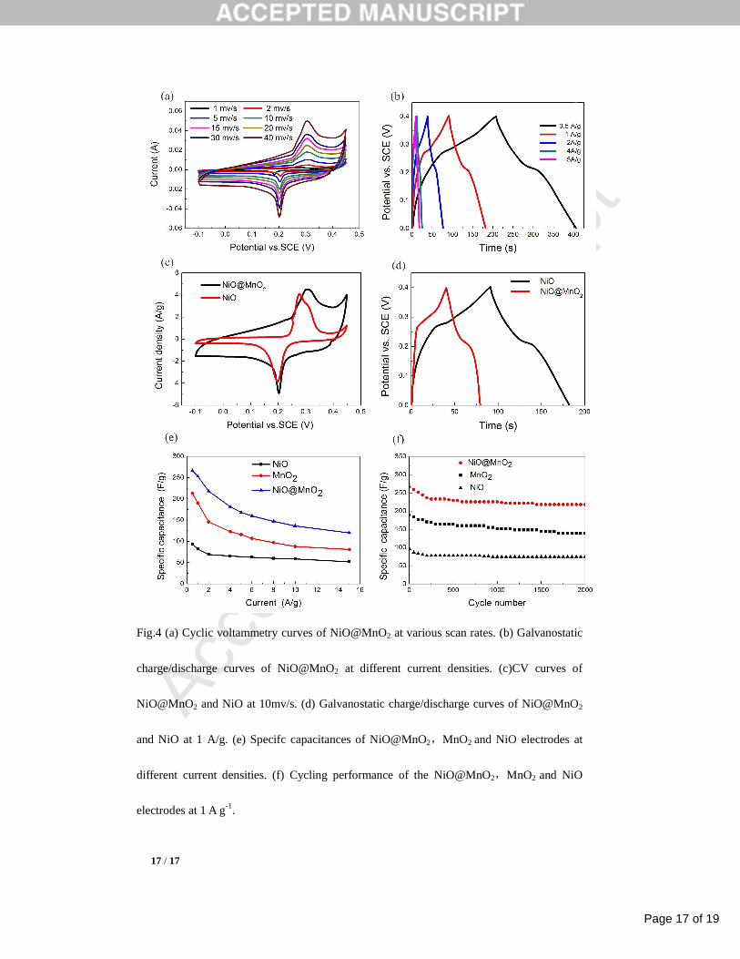
A detailed measurement of the electrochemical performance of NiO@MnO2 nanocomposites
are shown in Fig.4. CV curves of NiO@MnO2 are shown in the Fig.4 (a) at different scan rates in
a fixed potential range of -0.1~0.45 V (vs.SCE) in 2 M aqueous KOH electrolyte. A pair of
well-defined redox peaks is obviously observed in all CV curves, suggesting the typical
pseudocapacitive feature of active materials, which is obviously different from the electric
double-layer capacitance characterized by nearly rectangular CV curves, the redox couples
correspond to the reversible reactions of and Ni2+/Ni3+ transitions. The shape of the CV curves
barely changes, indicating that the electrode have a good rate capability. To further investigate the
electrochemical performance of the NiO@MnO2 electrode, we perform galvanostatic
charge–discharge (GCD) curves (Fig.4b) at various current densities in a fixed potential range of

Page 8 of 19
Accep
ted
Man
uscr
ipt
8 / 8
0~0.4 V (vs.SCE). The shape of charge-discharge curves is basically symmetric, suggesting good
reversibility redox processes. Voltage plateaus at around 0.28 V and 0.21 V can be seen in the
charge and discharge process respectively. The specific capacitances of the NiO@MnO2 are 266.7,
253.3, 218.3, 181.7, 168.3, 147.3F g-1 at current densities of 0.5, 1, 2, 4, 6, 8, 10 A g-1. CV curves
have been made comparison between NiO@MnO2 and NiO at 10 mv/s in the Fig.4(c), it can be
clearly seen that the CV curve of NiO@MnO2 electrode shows the higher integrated area than NiO
electrodes, furthermore, it also can be clearly seen that the GCD curves (Fig.3d) of NiO@MnO2
electrode shows the higher discharge time than NiO electrodes, indicating the higher specific
capacitance of NiO@MnO2 nanocomposites due to the optimal core-shell structure and the
introduction MnO2.
As shown in Fig.4 (e), contrasting with the specific capacitances of NiO@MnO2 and NiO
electrode at various charge/discharge current, the capacitance of NiO@MnO2 reduces from 266.7
F g-1 ( current density of 0.5 A g-1 ) to 120 F g-1 ( current density of 15 A g-1 ) with 45% of the
specific capacitance remaining, in the same process, the capacitance of NiO electrode reduces
from 94 F g-1 ( current density of 0.5 A g-1 ) to 52 F g-1 ( current density of 15 A g-1 ) with 55% of
the specific capacitance remaining, and the capacitance of MnO2 electrode reduces from 213 F g-1
( current density of 0.5 A g-1 ) to 81 F g-1 ( current density of 15 A g-1 ) with 38% of the specific
capacitance remaining. This result indicates that the specific capacitance of NiO and MnO2
electrode are both much lower than NiO@MnO2 electrode. The higher specific capacitance of
NiO@MnO2 electrode is due to ultrathin MnO2 nanosheets were well wrapped on the surface of
NiO microtubes to form a highly porous structure, the porous nanoarchitecture and MnO2
nanosheets provides the composites with larger surface area that means a large
Page 9 of 19
Accep
ted
Man
uscr
ipt
9 / 9
electrode/electrolyte contact interface and more active sites for electrochemical reactions. We
further studied the cycling performance (Fig.4 (f)) of the electrodes at 1 A g-1, the capacity
retention (81.7%) of NiO@MnO2 electrode shows higher than that of NiO electrode (77.4%) and
MnO2 electrode(73.5%) after 2000 charge-discharge cycles, the cycling performance of
NiO@MnO2 is very excellent because the core/shell structure is stable during repeated
charge-discharge process.
To further understand the fundamental electrochemical behavior of NiO@MnO2 composites,
EIS data of NiO,MnO2 and NiO@MnO2 electrode are shown in Fig.5(a). The impedance spectra
display similar form with a semicircle at a high-frequency region and a straight line at
low-frequency region. The intersection of the plot at the x-axis represents Rs of the
electrochemical system, which contains three sections: the intrinsic resistance of the substrate, the
resistance of the electrolyte and the contact resistance at the interface between active materials and
current collector[25], the Rs value of NiO@MnO2 (0.186 Ω) is bigger than that of NiO (0.120 Ω),
but which is smaller than that of MnO2 (0.373Ω). Rct stands for charge transfer resistance between
the electrode and the electrolyte[26], which corresponding to the diameter of a semicircle, the Rct
value of NiO@MnO2 (0.235 Ω) is much bigger than that of NiO (0.065 Ω), but which is also
smaller than that of MnO2 (0.373Ω). The slope of the straight line is related to the Warburg
impedance (Rw) which represents the electrolyte diffusion in the active materials[27], the higher is
the slope the easier is the ion diffusion/adsorption process, Warburg impedance is reduced when
the slope is increased, a line with large slope at low frequency illustrates that the ion diffusion in
the solution and the adsorption of ions onto the electrode surface occur swiftly, the Rw value of
NiO@MnO2 is higher than that of that of NiO, but which is smaller than that of MnO2. These
Page 10 of 19
Accep
ted
Man
uscr
ipt
10 / 10
results indicate the introduction of poor conductivity MnO2 lead to increase the solution resistance,
the charge transfer resistance and the Warburg impedance decrease. In fact, this is the reason why
the rate capability of NiO@MnO2 electrode is inferior to NiO electrode. Moreover, we also
calculate the specific capacitance NiO, MnO2, NiO@MnO2 from EIS data according to
1
2 ''C
fZ mπ=
where f is the operating frequency (Hz), ''Z is the imaginary parts of the total device resistance
(Ohm), and m is the mass of active materials in each electrode[28,29]. The result is shown in
Fig.5(b), the capacitance of them is high at low frequency, and it start to decrease with the
increasing frequency.
conclusion
In summary, we have successfully synthesized NiO@MnO2 core/shell nanocomposites with
distinct morphologies by a facile and scalable strategy. NiO@MnO2 nanocomposites show a high
specific capacitance of 266.7 F g-1 at 0.5 A g-1, excellent rate capability and remain at 81.7% of
initial capacitance after 2000 cycles at 1 A g-1. These results indicate that this kind of composites
with excellent electrochemical properties can be a promising electrode material for
supercapacitors.
Acknowledgments
This work was supported by the Research Fund for the Doctoral Program of Higher Education
of China under Grant no. 20136102110046, the Innovation Foundation of Shanghai Aerospace
Science and Technology Grant no. SAST201373 and the Graduate Starting Seed Fund of
Northwestern Polytechnical University (2015).

Page 11 of 19
Accep
ted
Man
uscr
ipt
11 / 11
References
[1] Z. Yu, M. McInnis, J. Calderon, S. Seal, L. Zhai, J. Thomas, Functionalized graphene aerogel
composites for high-performance asymmetric supercapacitors, Nano Energy, 11 (2015) 611-620.
[2] Z. Li, High-performance solid-state supercapacitors based on graphene-ZnO hybrid
nanocomposites, Nanoscale Res. Lett., 8 (2013) 11479-11487.
[3] G. Zhang, L. Yu, H.E. Hoster, X.W. Lou, Synthesis of one-dimensional hierarchical NiO
hollow nanostructures with enhanced supercapacitive performance, Nanoscale, 5 (2013)
877-881.
[4] F. Li, Y. Xing, M. Huang, K.L. Li, T.T. Yu, Y.X. Zhang, D. Losic, MnO2 nanostructures with
three-dimensional (3D) morphology replicated from diatoms for high-performance
supercapacitors, J. Mater. Chem. A, 3 (2015) 7855-7861.
[5] Y. Wang, Y. Lei, J. Li, L. Gu, H. Yuan, D. Xiao, Synthesis of 3D-nanonet hollow structured
Co3O4 for high capacity supercapacitor, ACS Appl. Mater. Interfaces, 6 (2014) 6739-6747.
[6] E. Jokar, A. zad, S. Shahrokhian, Synthesis and characterization of NiCo2O4 nanorods for
preparation of supercapacitor electrodes, J. Solid State Electrochem., 19 (2015) 269-274.
[7] J. Liu, J. Jiang, M. Bosman, H.J. Fan, Three-dimensional tubular arrays of MnO2-NiO
nanoflakes with high areal pseudocapacitance, J. Mater. Chem., 22 (2012) 2419-2426.
[8] S.I. Kim, J.S. Lee, H.J. Ahn, H.K. Song, J.H. Jang, Facile route to an efficient NiO
supercapacitor with a three-dimensional nanonetwork morphology, ACS Appl. Mater. Interfaces,
5 (2013) 1596-1603.
[9] Z. Yu, B. Duong, D. Abbitt J. Thomas, Highly ordered MnO2 nanopillars for enhanced
supercapacitor performance, Adv. Mater., 25 (2013) 3302-3306.
Page 12 of 19
Accep
ted
Man
uscr
ipt
12 / 12
[10] L. Li, Z.A. Hu, N. An, Y.Y. Yang, Z.M. Li, H.Y. Wu, Facile Synthesis of MnO2/CNTs
Composite for Supercapacitor Electrodes with Long Cycle Stability, J. Phys. Chem. C, 118
(2014) 22865-22872.
[11] Z. Yu, J. Thomas, Energy storing electrical cables: Integrating energy storage and electrical
conduction, Adv. Mater., 26 (2014) 4279-4285.
[12] X. Gao, Y. Zhang, M. Huang, F. Li, C. Hua, L. Yu, H. Zheng, Facile synthesis of
Co3O4@NiCo2O4 core–shell arrays on Ni foam for advanced binder-free supercapacitor
electrodes, Ceram Int, 40 (2014) 15641-15646.
[13] W. Yang, Z. Gao, J. Ma, X. Zhang, J. Wang, J. Liu, Hierarchical NiCo2O4@NiO core-shell
hetero-structured nanowire arrays on carbon cloth for a high-performance flexible all-solid-state
electrochemical capacitor, J. Mater. Chem. A, 2 (2014) 1448-1457.
[14] D. Cai, D. Wang, B. Liu, L. Wang, Y. Liu, H. Li, Y. Wang, Q. Li, T. Wang,
Three-Dimensional Co3O4@NiMoO4 Core/Shell Nanowire Arrays on Ni Foam for
Electrochemical Energy Storage, ACS Appl. Mater. Interfaces, 6 (2014) 5050-5055.
[15] X. Liu, S. Shi, Q. Xiong, L. Li, Y. Zhang, H. Tang, C. Gu, X. Wang, J. Tu, Hierarchical
NiCo2O4@ NiCo2O4 core/shell nanoflake arrays as high-performance supercapacitor materials,
ACS Appl. Mater. Interfaces, 5 (2013) 8790-8795.
[16] Z. Yu, L. Tetard, L. Zhai, J. Thomas, Supercapacitor electrode materials: Nanostructures
from 0 to 3 dimensions, Energy Environ. Sci., 8 (2015) 702-730.
[17] M. Huang, F. Li, Y.X. Zhang, B. Li, X. Gao, Hierarchical NiO nanoflake coated CuO flower
core–shell nanostructures for supercapacitor, Ceram. Int., 40 (2014) 5533-5538.
Page 13 of 19
Accep
ted
Man
uscr
ipt
13 / 13
[18] N. Wang, L. Chen, X. Ma, J. Yue, F. Niu, H. Xu, J. Yang, Y. Qian, Facile synthesis of
hierarchically porous NiO micro-tubes as advanced anode materials for lithium-ion batteries, J.
Mater. Chem. A, 2 (2014) 16847-16850.
[19] M. Chigane, M. Ishikawa, Manganese oxide thin film preparation by potentiostatic
electrolyses and electrochromism, J. Electrochem. Soc., 147 (2000) 2246-2251.
[20] Z. Liu, Q. Xu, J. Wang, N. Li, S. Guo, Y. Su, H. Wang, J. Zhang, S. Chen, Facile
hydrothermal synthesis of urchin-like NiCo2O4 spheres as efficient electrocatalysts for oxygen
reduction reaction, Int. J. Hydrogen Energy, 38 (2013) 6657-6662.
[21] J. Xiao, S. Yang, Bio-inspired synthesis of NaCl-type CoxNi1-xO (0 [less-than-or-equal] x < 1)
nanorods on reduced graphene oxide sheets and screening for asymmetric electrochemical
capacitors, J. Mater. Chem., 22 (2012) 12253-12262.
[22] J. Yan, Z. Fan, T. Wei, W. Qian, M. Zhang, F. Wei, Fast and reversible surface redox reaction
of graphene–MnO2 composites as supercapacitor electrodes, Carbon, 48 (2010) 3825-3833.
[23] H. Xia, M. Lai, L. Lu, Nanoflaky MnO2/carbon nanotube nanocomposites as anode materials
for lithium-ion batteries, J. Mater. Chem., 20 (2010) 6896-6902.
[24] Y. Zhao, P. Jiang, MnO2 nanosheets grown on the ZnO-nanorod-modified carbon fibers for
supercapacitor electrode materials, Colloids Surf., A, 444 (2014) 232-239.
[25] X. Xie, C. Zhang, M.-B. Wu, Y. Tao, W. Lv, Q.-H. Yang, Porous MnO2 for use in a high
performance supercapacitor: replication of a 3D graphene network as a reactive template, Chem
Commun, 49 (2013) 11092-11094.
Page 14 of 19
Accep
ted
Man
uscr
ipt
14 / 14
[26] B. Yan, X. Li, Z. Bai, M. Li, L. Dong, D. Xiong, D. Li, Superior lithium storage performance
of hierarchical porous vanadium pentoxide nanofibers for lithium ion battery cathodes, J. Alloys
Compd, 634 (2015) 50-57.
[27] Y. Luo, H. Zhang, D. Guo, J. Ma, Q. Li, L. Chen, T. Wang, Porous NiCo2O4-reduced
graphene oxide (rGO) composite with superior capacitance retention for supercapacitors,
Electrochim. Acta, 132 (2014) 332-337.
[28] I. Stepniak, A. Ciszewski, Grafting effect on the wetting and electrochemical performance of
carbon cloth electrode and polypropylene separator in electric double layer capacitor, J. Power
Sources, 195 (2010) 5130–5137.
[29] J. Kang, J. Wen, S.H. Jayaram, A. Yu, X. Wang, Development of an equivalent circuit model
for electrochemical double layer capacitors (EDLCs) with distinct electrolytes, Electrochim.
Acta, 115 (2014) 587-598.

Page 15 of 19
Accep
ted
Man
uscr
ipt
15 / 15
Fig.1 (a) Schematic illustration of the formation of NiO@MnO2. (b) SEM image of
Ni(dmg)2 and (c, d) NiO mircrotube, (e, f) SEM and TEM image of NiO@MnO2. (g)
HRTEM image of NiO@MnO2 and SEAD Pattern of NiO@MnO2. (g) Corresponding
EDS spectrum of NiO@MnO2.

Page 16 of 19
Accep
ted
Man
uscr
ipt
16 / 16
Fig.2 (a) XRD pattern of the NiO@MnO2 nanocomposites, (b)TG Curve of Ni(dmg)2
nanorod.
Fig.3 XPS spectra of (a) survey spectrum, (b)O 1s, (c)Ni 2p and (d) Mn 2p for NiO@MnO2
nanocomposites.
Page 17 of 19
Accep
ted
Man
uscr
ipt
17 / 17
Fig.4 (a) Cyclic voltammetry curves of NiO@MnO2 at various scan rates. (b) Galvanostatic
charge/discharge curves of NiO@MnO2 at different current densities. (c)CV curves of
NiO@MnO2 and NiO at 10mv/s. (d) Galvanostatic charge/discharge curves of NiO@MnO2
and NiO at 1 A/g. (e) Specifc capacitances of NiO@MnO2,MnO2 and NiO electrodes at
different current densities. (f) Cycling performance of the NiO@MnO2,MnO2 and NiO
electrodes at 1 A g-1.

Page 18 of 19
Accep
ted
Man
uscr
ipt
18 / 18
Fig.5(a) EIS data of NiO,MnO2 and NiO@MnO2 electrode, (b) specific capacitance plot
vs. frequnency of NiO,MnO2 and NiO@MnO2 electrode.

Page 19 of 19
Accep
ted
Man
uscr
ipt
*Graphical Abstract (for review)