synthesis of open-cell metal foams by templated directed vapor
TRANSCRIPT
Synthesis of open-cell metal foams by templated directedvapor deposition
Douglas T. Queheillalt, Derek D. Hass, David J. Sypeck, and Haydn N.G. WadleyDepartment of Materials Science and Engineering, School of Engineering and Applied Science,University of Virginia, Charlottesville, Virginia 22904
(Received 6 September 2000; accepted 17 January 2001)
Low-density, open-cell nickel base superalloy foams have been synthesized by ahigh-rate, electron beam-directed vapor deposition process and their mechanicalproperties evaluated. The deposition process uses an open-cell polymer foam templateupon which is deposited a metal alloy coating. The electron beam evaporated flux wasentrained in a rarefied transonic gas jet and propagated along the flow stream linesthrough the polymer structure. After vapor deposition, the polymer template wasremoved by low-temperature thermal decomposition. The resultant ultralightweightmetal foams consisted of a three-dimensional open cell, reticulated structure possessinghollow triangular ligaments with relative densities of <3%. Their mechanical integritywas increased by either pressureless or transient liquid phase sintering. The mechanicalproperties of these ultralightweight metal foams were comparable to theoreticalpredictions for open-cell, reticulated foams.
I. INTRODUCTION
Ultralightweight cellular solids can be manufacturedfrom numerous metals and metal alloys by a wide varietyof methods.1 The properties of these materials dependupon the properties of the metal, the relative density ofthe foam, and the distribution of material within the foam(e.g., open or closed cell, cell size, etc.)2–4 Closed-cellmetal foams possess high modulus and strength charac-teristics, high impact energy absorbing characteristics,5,6
very low thermal conductivities,7 and excellent acousticdamping characteristics,8,9 when compared with themetal from which they are made. Open-cell foams are notas stiff or as strong, but they posses characteristics whichcan be exploited in multifunctional load supporting andheat dissipation applications because of the ability toflow fluids readily through the heated structure.10,11
They also have a high surface area to volume ratio andcan be used as high-temperature supports for catalystsand electrodes in electrochemical cells.
Numerous solid- and liquid-state processes have beendeveloped for the manufacture of closed-cell metalfoams and porous solids. These include melt gas injec-tion, gas releasing particle decomposition in melts andsemisolids, gas metal eutectic solidification, and en-trapped gas expansion.1 These methods result in foamswith cell sizes ranging from 100mm to 5 cm and rela-tive densities from 0.05 to 1.0. The synthesis of open-cell metal foams can be accomplished by investmentcasting using an open-cell mold,12 electrolytic deposi-tion,13–19and chemical20 or physical22–24vapor deposition
on polymer templates. The as-deposited structuresare subjected to a low-temperature thermal treatmentduring which the parent polymer template is thermallydecomposed. This is usually followed by a high-temperature sintering treatment to densify the ligaments.These methods result in foams with cell sizes rangingfrom 100mm to 5 mm and relative densities from 0.01 to0.15.
The electrolytic deposition process involves the disso-lution of one electrode (an anode) and the deposition ofthis metal on a second electrode (the polymer templatecathode). Because polymer-based foams are nonconduc-tive, they must be made electrically conductive by eithersputtering or ionic deposition. The metal foam is thencreated by the subsequent electrolytic deposition of el-emental Ni or Cu. Metal foams produced by this methodare currently manufactured under the trade names Celmet(Sumitomo Electric, Osaka, Japan) and Metapore (Soci-ete Sorapec, Fontenay Sous Bois, France) for use in Ni–Cd and Ni–metal hydride batteries and catalytic devices.A major limitation of electroless deposition processes isthat deposition is limited to a few metallic elements (al-loys are difficult). In addition, deposition rates are low(approximately 0.2–2.0mm/min), and nonuniform depo-sition may occur due to uneven field distributions overirregular shaped objects. The resultant foams often ex-hibit poor physical and mechanical properties because oftheir pure metal composition.
Chemical vapor deposition (CVD) of a metal carbonylgas has also been used to manufacture metal foams.20–22
Pure (>99 wt% Ni) metal foams manufactured by
J. Mater. Res., Vol. 16, No. 4, Apr 2001 © 2001 Materials Research Society1028

thermal decomposition of Ni(CO4) gas are produced byInco Limited (Toronto, Ontario, Canada) under the tradename Incofoam. It is increasingly used for the nickelelectrode of rechargeable batteries. Refractory metalfoams (i.e., Zr, Nb, Hf, Ta, W, and Re) produced bychemical vapor infiltration (CVI) are also manufacturedby Ultramet Advanced Materials (Pacoima, CA) and Re-cemat International (The Netherlands) under the tradenames Ultrametal and Recemat. Potential applicationsinclude thermal insulation, lightweight nozzle flaps foradvanced turbine engines, aerobraking structures, aircraftwing and fuselage structures, molten metal, and catalyticfiltration devices. Advantages of the CVD and CVI proc-esses include high throwing power resulting in highdeposition rates, non-line-of-sight deposition, relativelyinexpensive capital equipment costs (because it is a low-vacuum process) and the ability to deposit both elementalmetals and some alloys. However, vapor decompositionof the least expensive chemical precursors occurs at hightemperatures where the thermal stability of the polymertemplate must be taken into consideration. The need touse toxic, low decomposition temperature chemical pre-cursors results in a costly process that is difficult toimplement in an environmentally satisfactory manner.
Physical vapor deposition (PVD) techniques includingmetal spray deposition, thermal evaporation, reactivesputtering, and arc-vapor deposition have also been usedto manufacture metal foams.22–24The arc-vapor deposi-tion process developed by Vapor Technologies, Inc.(Boulder, CO), and other conventional PVD processesinvestigated by Montedison (Milan, Italy) have been pat-ented in recent years. However, PVD processes suchas these offer a number of potential advantages includingthe ability to deposit most metal elements and manyof their alloys and to even create foams with multilayeredor functionally graded metal ligaments. However,because these processes operate in high vacuum(10−5–10−9 torr), they coat only the surfaces that are inthe line-of-sight of the vapor source. This is likely to resultin uneven coating of the polymer template, depending onthe cell size. In addition, low deposition rates (less than2 mm/min), low materials utilization factors, and difficultiesin maintaining stoichiometry for alloys whose constitu-ents possess widely varying vapor pressures can imposeconstraints upon the use of conventional PVD techniquesfor the low-cost synthesis of metal foams.
Here, we explore the application of an electron beam-directed vapor deposition (EB-DVD) approach for syn-thesizing open cell metal alloy foams. In the EB-DVDapproach, electron beam-evaporated vapor is entrained ina rarefied transonic gas jet and propagated through apolymer foam template. We show that low-density metalfoams can be created in this manner and report on themechanical properties of foams made from a high-temperature, corrosion resistant nickel-based superalloy.
II. DEPOSITION METHODOLOGY
Electron beam evaporation is a widely used methodfor the high-rate production of atomic and molecular va-por.25 Normally, vapor is ballistically transported to asubstrate under high-vacuum conditions where it con-denses on surfaces that are in the line-of-sight of the fluxsource. However, by intersecting the vapor plume with ararefied trans- or supersonic inert gas jet, it is possible toentrain the evaporated flux in a nonreacting gas flow andtransport it to a substrate under low-vacuum (0.1–10 torr)conditions.26,27Deposition of the atomistic flux then oc-curs by gas phase scattering from the stream lines of theflow.28 A schematic illustration of such an electronbeam-directed vapor deposition (EB-DVD) process isshown in Fig. 1. The system used for deposition con-sisted of a 60 kV/10 kW axial electron beam gun (modi-fied to function in a low vacuum environment) and a Hecarrier gas jet. A more complete description of the EB-DVD system and its available processing range can befound elsewhere.28,29
When the gas jet intersects an object, the stream linespass around the object. Scattering of the condensable fluxfrom this flow then enables non-line-of-sight deposition.
FIG. 1. Schematic diagram of the EB-DVD processing chambershowing the introduction of a carrier gas flow into the chamberthrough a nozzle which transports the evaporated source materialthrough the polymer template.
D.T. Queheillalt et al.: Synthesis of open-cell metal foams by templated directed vapor deposition
J. Mater. Res., Vol. 16, No. 4, Apr 2001 1029

The degree to which blind surfaces can be coated is acomplicated function of the objects shape, the flow fieldnear it, the composition of the flow, and the collisioncross section of the material to be deposited. As a result,there exists an optimal set of process conditions that arebest suited for each objects coating. These are controlledby the electron beam power and scan pattern on the metalsource, the gas inlet nozzle flow pressure, the operatingchamber pressure, and the nozzle geometry. These can allbe significantly varied facilitating wide processing con-dition variations.
For the deposition experiments reported here, cylindri-cal samples were used (25.4 mm in length and 12.7 mmin diameter) as the deposition template. They consistedof open-cell, reticulated polyurethane foams with a poresize of approximately 0.85 mm (30 pores/in. nominal).The polymer foam was positioned 7.0 cm from thenozzle and 5.0 cm from the vapor source. The polymerfoam templates were rotated about its cylindrical axis atapproximately 1 revolution/min and also translated axi-ally through the vapor flux region to promote uniformdeposition and complete infiltration. Several trial depo-sition experiments were conducted using different com-binations of upstream and process chamber pressures andgas flow rates. At low process pressures (0.30 torr), fluxscattering from the stream lines resulted in thick coatingsat the exterior of the sample. Very low process pressuresenhance line-of-site coating and incomplete coverage ofligaments. Intermediate process pressures of 0.07 torrresulted in best ligament coating uniformity. The finaloperating conditions selected for the deposition usedan electron beam power4 2100 W, He gas flow43.5 standard L/min, chamber pressure4 0.07 torr, andupstream nozzle pressure4 0.68 torr. During deposi-tion, some heating of the substrate occurred. The processconditions ensured the temperature remained below ap-proximately 100 °C to prevent slumping of the polymertemplate during deposition. Variation of the depositiontime allowed the metal thickness to be varied.
An Inconel alloy 625 nickel-based superalloy of nomi-nal composition Ni–21.3 Cr–8.8 Mo–3.9 Nb –0.13 Al–0.19 Ti wt% was used for deposition. Conventional ingotprocessed Inconel alloy 625 is a non-age-hardenable,solid solution alloy with a face centered cubic (g-phase)crystal structure. It is microstructurally stable up to650 °C. The high alloying element concentrations makethe alloy well suitable for high-temperature applicationswhere corrosion and especially pitting resistance are re-quired. Nominal properties for the fully dense polycrys-talline alloy are the following: yield strength,sys 4414 MPa; Young’s modulus,E 4 208 GPa; shear modu-lus, G 4 81 GPa; density,r 4 8.44 g/cm3.30
After deposition, the polymer template was removedby a thermal decomposition step. Typically, metal foammanufacturers remove the polymer templates by heating
in an atmosphere containing oxygen. The burnout con-ditions determine the amount of residual carbon whichremains to potentially contaminate the metal foam. Vari-ous decomposition approaches have been explored. Inone, the polymer was heated at approximately 1 °C/minor less to a temperature between 350 and 500 °C inair.15,23In another, metal-coated polymer templates wererapidly exposed (less than about 5 s) to a temperature ofat least 600 °C (in air) to thermally decompose the poly-mer template. This latter process caused the gaseous oxi-dation products to form a large internal pressure andcreated burst holes in the metal layer.33 Here, the poly-urethane templates were removed by thermally decom-posing the polymer in vacuum (approximately 10−5 torr)by heating at 1 °C/min to 250 °C and holding for 2 h.This resulted in complete removal of the polymer corewith minimal carbon residue.
After thermal decomposition, the samples were eitherpressureless sintered or transient liquid-phase sintered.Pressureless sintering consisted of heating the samples ata rate of 10 °C/min up to 1150 °C, holding for 12 h fol-lowed by furnace cooling at approximately 25 °C/min invacuum (approximately 10−5 torr). For transient liquidphase sintering, an alloy powder with a nominal compo-sition of Ni–25.0 Cr–10.0 P–0.03 C wt% (Nicrobraz 51)was used. To apply this liquid phase sintering material,40–100-mm-diameter braze powder was mixed with abinder and applied throughout the foam using an air pow-ered fluidized bed. The samples were then heated at arate of 10 °C/min up to 550 °C, holding for 1 h (to vola-tilize the binder), and then continued heating to 1120 °C,holding for 2 h followed by furnace cooling at approxi-mately 25 °C/min. In all cases, the mass of liquid-phasesintering agent added was less than 5% of the mass ofdeposited metal foam.
The morphology of the EB-DVD foam structures wasevaluated by scanning electron microscopy (SEM) andfocused ion beam microscopy (FIB). X-ray diffraction(XRD) patterns and the lattice parameters (evaluatedfrom {111} peaks) were obtained using Cu Ka radiationand a scan rate of 0.02 deg/min. The mechanical proper-ties of the foams were determined using uniaxial com-pression tests at a strain rate of 0.024 min−1. Becausethe initial loading of a metal foam may not accuratelyrepresent the true elastic modulus, each foam wasloaded and unloaded at 2, 4, 6, 8, and 10% strain andthe Young’s modulus was calculated from the unload-ing curve.
III. RESULTS AND DISCUSSION
A. Coating morphology
The morphology of the directed vapor-deposited foamand the polymer template used for its synthesis is shownin Fig. 2. It can be seen in Fig. 2(a) that the reticulated
D.T. Queheillalt et al.: Synthesis of open-cell metal foams by templated directed vapor deposition
J. Mater. Res., Vol. 16, No. 4, Apr 20011030

polymer foam template had cusp-shaped ligaments withtriangular cross sections. The as-deposited metal foamtherefore had hollow ligaments with cusp-shaped trian-gular interior voids, Fig. 2(b). The metal thickness wasfound to be similar on each of the three sides of theligaments. However, some thickening at the apex wasobserved. This appears to be a manifestation of thehigher flux view factor at these locations. Sectioning in-dicated that the coating thickness decreased slowly withdepth into the foam. For the samples synthesized here,the coating thickness on interior ligaments was approxi-mately 20% less than that on ligaments located on thesamples exterior. Therefore, we expect interior locatedcells to be more compliant than cell located around thecircumference of the samples.
B. Microstructural analysis
1. As-deposited condition
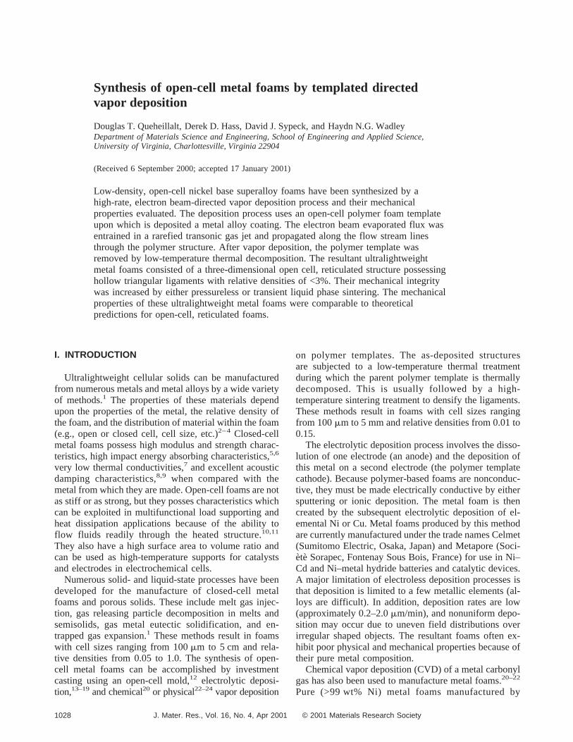
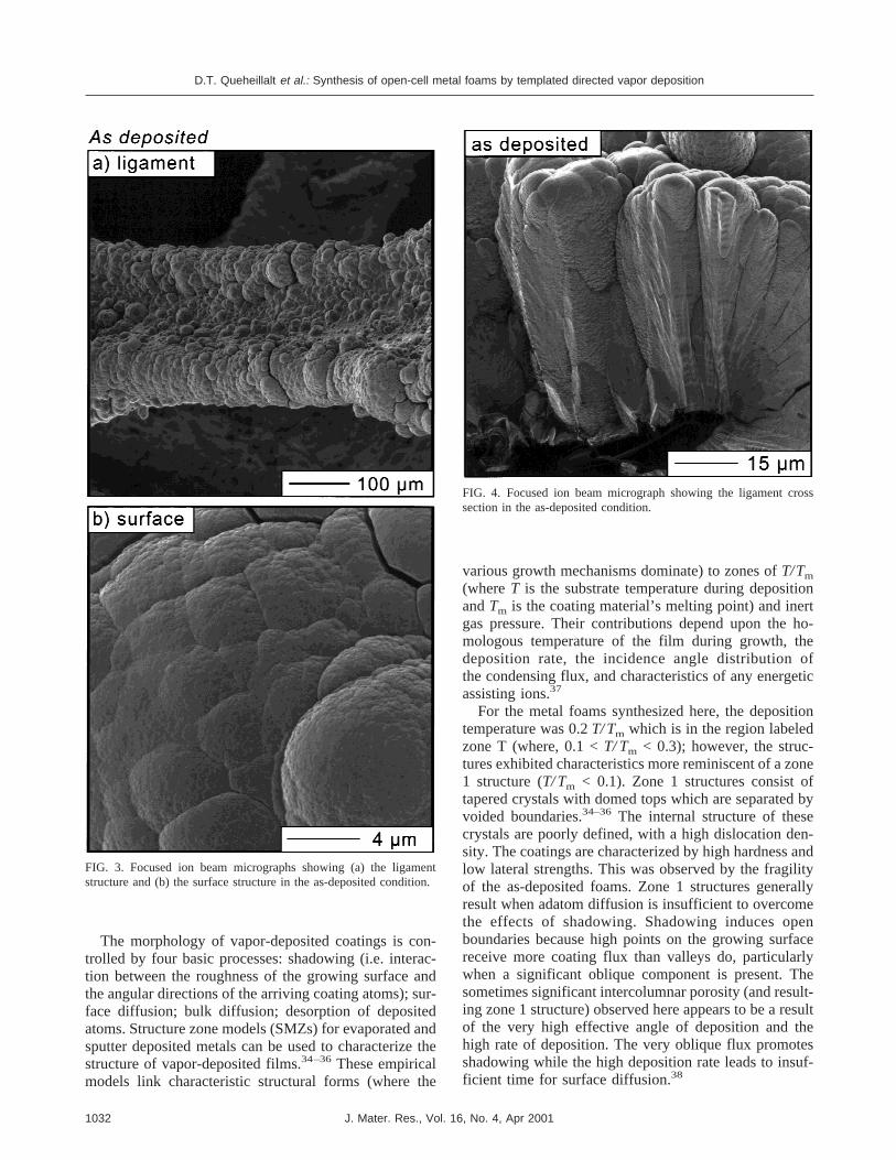
The morphology of the EB-DVD foams in the as-deposited condition is shown in Fig. 3. The as-depositedmicrostructure had a fractal surface created by the com-petitive growth of tapered columns, Fig. 3(a). The pri-mary domed surface features were approximately 5mmin diameter and in some cases exhibited intercolumnarcracking, Fig. 3(b). Some of the tapered columns ex-tended from the substrate to the coating surface whileothers had nucleated in the coating and extended to thesurface, Fig. 4. In general, the intercolumnar crackingwas locally perpendicular to the deposition surface.
FIG. 2. Micrographs showing the structure of (a) the parent reticulated polymer foam with solid ligaments and (b) the EB-DVD metal foampossessing hollow ligaments after the thermal decomposition treatment.
D.T. Queheillalt et al.: Synthesis of open-cell metal foams by templated directed vapor deposition
J. Mater. Res., Vol. 16, No. 4, Apr 2001 1031
The morphology of vapor-deposited coatings is con-trolled by four basic processes: shadowing (i.e. interac-tion between the roughness of the growing surface andthe angular directions of the arriving coating atoms); sur-face diffusion; bulk diffusion; desorption of depositedatoms. Structure zone models (SMZs) for evaporated andsputter deposited metals can be used to characterize thestructure of vapor-deposited films.34–36These empiricalmodels link characteristic structural forms (where the
various growth mechanisms dominate) to zones ofT/Tm
(whereT is the substrate temperature during depositionandTm is the coating material’s melting point) and inertgas pressure. Their contributions depend upon the ho-mologous temperature of the film during growth, thedeposition rate, the incidence angle distribution ofthe condensing flux, and characteristics of any energeticassisting ions.37
For the metal foams synthesized here, the depositiontemperature was 0.2T/ Tm which is in the region labeledzone T (where, 0.1 <T/ Tm < 0.3); however, the struc-tures exhibited characteristics more reminiscent of a zone1 structure (T/ Tm < 0.1). Zone 1 structures consist oftapered crystals with domed tops which are separated byvoided boundaries.34–36 The internal structure of thesecrystals are poorly defined, with a high dislocation den-sity. The coatings are characterized by high hardness andlow lateral strengths. This was observed by the fragilityof the as-deposited foams. Zone 1 structures generallyresult when adatom diffusion is insufficient to overcomethe effects of shadowing. Shadowing induces openboundaries because high points on the growing surfacereceive more coating flux than valleys do, particularlywhen a significant oblique component is present. Thesometimes significant intercolumnar porosity (and result-ing zone 1 structure) observed here appears to be a resultof the very high effective angle of deposition and thehigh rate of deposition. The very oblique flux promotesshadowing while the high deposition rate leads to insuf-ficient time for surface diffusion.38
FIG. 3. Focused ion beam micrographs showing (a) the ligamentstructure and (b) the surface structure in the as-deposited condition.
FIG. 4. Focused ion beam micrograph showing the ligament crosssection in the as-deposited condition.
D.T. Queheillalt et al.: Synthesis of open-cell metal foams by templated directed vapor deposition
J. Mater. Res., Vol. 16, No. 4, Apr 20011032
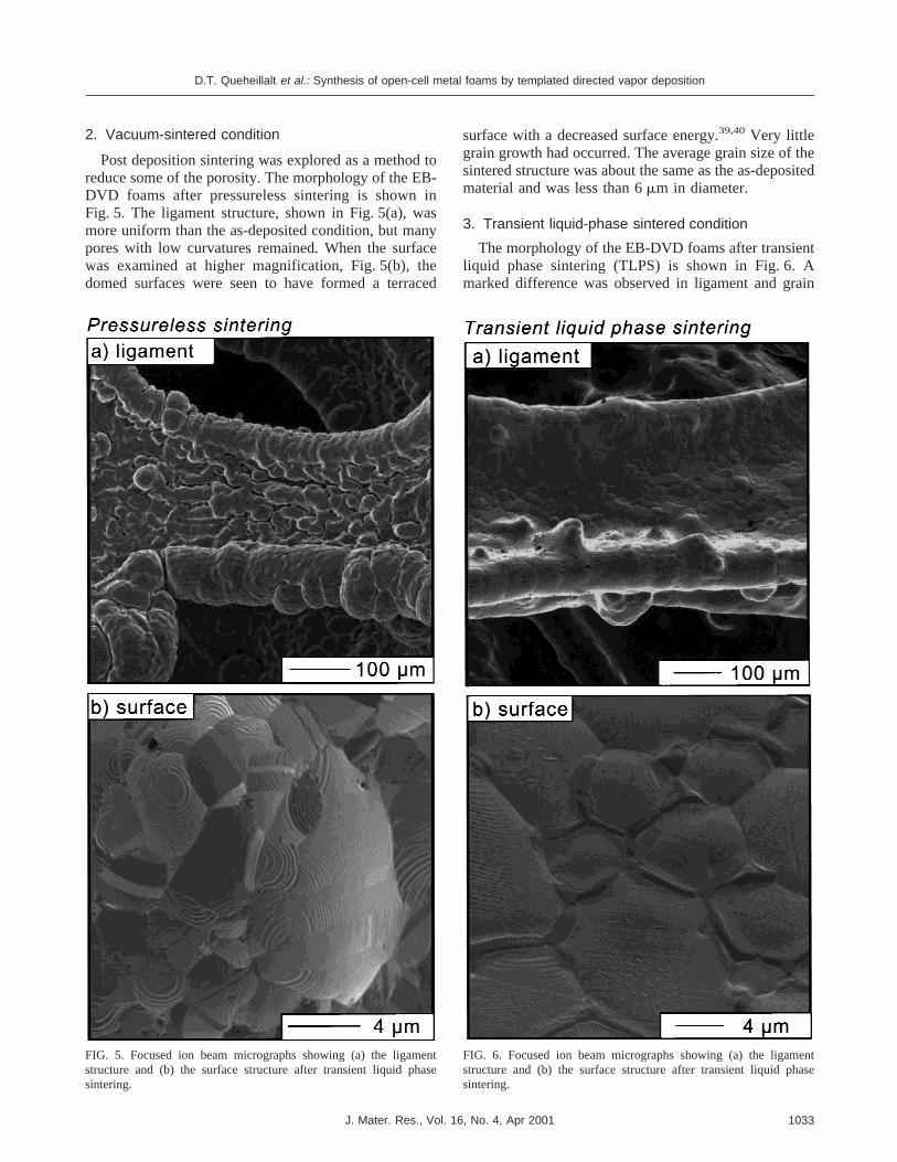
2. Vacuum-sintered condition
Post deposition sintering was explored as a method toreduce some of the porosity. The morphology of the EB-DVD foams after pressureless sintering is shown inFig. 5. The ligament structure, shown in Fig. 5(a), wasmore uniform than the as-deposited condition, but manypores with low curvatures remained. When the surfacewas examined at higher magnification, Fig. 5(b), thedomed surfaces were seen to have formed a terraced
surface with a decreased surface energy.39,40 Very littlegrain growth had occurred. The average grain size of thesintered structure was about the same as the as-depositedmaterial and was less than 6mm in diameter.
3. Transient liquid-phase sintered condition
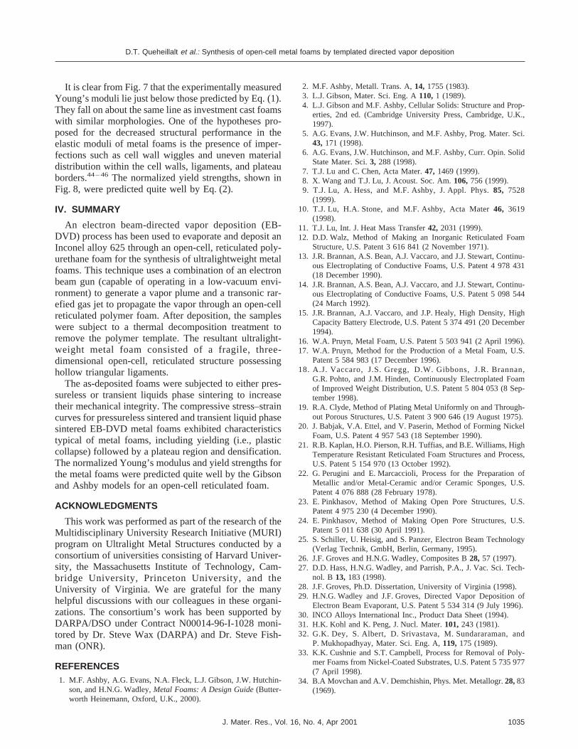
The morphology of the EB-DVD foams after transientliquid phase sintering (TLPS) is shown in Fig. 6. Amarked difference was observed in ligament and grain
FIG. 5. Focused ion beam micrographs showing (a) the ligamentstructure and (b) the surface structure after transient liquid phasesintering.
FIG. 6. Focused ion beam micrographs showing (a) the ligamentstructure and (b) the surface structure after transient liquid phasesintering.
D.T. Queheillalt et al.: Synthesis of open-cell metal foams by templated directed vapor deposition
J. Mater. Res., Vol. 16, No. 4, Apr 2001 1033

structure when compared with the pressureless sinteredsamples. In the transient liquid phase process, a low melt-ing temperature eutectic liquid forms as the melting pointdepressant (MPD) dissolves the base material andspreads through capillary action as the sample is heatedto the bonding temperature.41,42 The liquid films under-goes isothermal solidification as the MPD diffuses intothe base metal at a rate dependent on the diffusion con-stants in the bulk. The fluid film aids densification andreduces porosity and defect concentrations (i.e., pinholes,cracks, fissures), Fig. 6(a). During this solution reprecipi-tation step microstructural coarsening occurs, and signifi-cant grain growth was observed, Fig. 6(b). This occursbecause the solubility of a grain in its surrounding liquidvaries inversely with the grains size; small grains have ahigher solubility than coarse grains. The difference insolubility establishes a concentration gradient in the liq-uid, and material is transported from the small grains tothe large grains by diffusion. The net result is a progres-sive growth of larger grains with an average grain diam-eter of less than 12mm in diameter.
C. X-ray diffraction
X-ray diffraction patterns of Inconel alloy 625 for arandom powder distribution, the initial bar used forevaporation, and the as-deposited EB-DVD coating wereanalyzed. All of the XRD patterns display characteristicsof a high Ni face centered cubic alloy. The lattice pa-rameters of the three alloys were determined from the{111} peaks. The lattice parameter of the powder and barstock was determined to bea0 4 0.3603 nm where theEB-DVD alloy was slightly smaller (a0 4 0.3557 nm).Both are greater than the lattice parameter for pure Ni(a0 4 0.3524 nm).43 These values are close to a previ-ously determined lattice parameter of 0.3600 nm for CPSInconel alloy 625.31,32 The slight lattice contraction ofthe vapor deposited alloy is indicative of a slightly re-duced alloy element concentration. The EB-DVD alloyexhibited a decrease in the relative amount of {200} andan increase in the relative amounts of {220} orientedgrains in addition to significant lattice distortion. Duringsintering treatments, the texture was reduced due to re-crystallization of the microstructure.
D. Mechanical behavior
1. Uniaxial compression
Compressive stress–strain curves for the pressurelessand the transient liquid phase sintered foams exhibitedcharacteristics typical of metal foams, including yielding(i.e., plastic collapse) followed by a plateau region andthen densification. The stress–strain curves exhibited ser-rated striations in the plateau region and were a result oflocalized fracture of individual or small groups of cells.
The normalized Young’s modulus (defined as themodulus of the foam,E*, divided by the modulus ofthe parent solid,ES) and the normalized compressiveyield strength (defined as the yield strength of the foam,s*, divided by the yield strength of the parent solid,ss)were measured from the stress–stain curves of sampleswith a range of densities, Figures 7 and 8, respectively.Also shown are Gibson and Ashby4 theoretical relation-ships for the normalized Young’s modulus of an open-cell reticulated foam:
E*
Es= kSr*
rsD2
, (1)
wherer* is the density of the foam,rs is the density ofthe parent solid, and the factork ≈ 1.0 for the upperbound andk ≈ 0.1 for the lower bound.4 A similar rela-tionship has been developed for the normalized yieldstrength:
s*
ss= 0.3Sr*
rsD3/2
. (2)
FIG. 7. Normalized Young’s modulus (E*/ES) versus relative density(r*/rS) for the EB-DVD Inconel alloy 625 metal foams.
FIG. 8. Normalized yield strength (s*/sS) versus relative density (r*/rS) for the EB-DVD Inconel alloy 625 metal foams.
D.T. Queheillalt et al.: Synthesis of open-cell metal foams by templated directed vapor deposition
J. Mater. Res., Vol. 16, No. 4, Apr 20011034
It is clear from Fig. 7 that the experimentally measuredYoung’s moduli lie just below those predicted by Eq. (1).They fall on about the same line as investment cast foamswith similar morphologies. One of the hypotheses pro-posed for the decreased structural performance in theelastic moduli of metal foams is the presence of imper-fections such as cell wall wiggles and uneven materialdistribution within the cell walls, ligaments, and plateauborders.44– 46 The normalized yield strengths, shown inFig. 8, were predicted quite well by Eq. (2).
IV. SUMMARY
An electron beam-directed vapor deposition (EB-DVD) process has been used to evaporate and deposit anInconel alloy 625 through an open-cell, reticulated poly-urethane foam for the synthesis of ultralightweight metalfoams. This technique uses a combination of an electronbeam gun (capable of operating in a low-vacuum envi-ronment) to generate a vapor plume and a transonic rar-efied gas jet to propagate the vapor through an open-cellreticulated polymer foam. After deposition, the sampleswere subject to a thermal decomposition treatment toremove the polymer template. The resultant ultralight-weight metal foam consisted of a fragile, three-dimensional open-cell, reticulated structure possessinghollow triangular ligaments.
The as-deposited foams were subjected to either pres-sureless or transient liquids phase sintering to increasetheir mechanical integrity. The compressive stress–straincurves for pressureless sintered and transient liquid phasesintered EB-DVD metal foams exhibited characteristicstypical of metal foams, including yielding (i.e., plasticcollapse) followed by a plateau region and densification.The normalized Young’s modulus and yield strengths forthe metal foams were predicted quite well by the Gibsonand Ashby models for an open-cell reticulated foam.
ACKNOWLEDGMENTS
This work was performed as part of the research of theMultidisciplinary University Research Initiative (MURI)program on Ultralight Metal Structures conducted by aconsortium of universities consisting of Harvard Univer-sity, the Massachusetts Institute of Technology, Cam-bridge University, Princeton University, and theUniversity of Virginia. We are grateful for the manyhelpful discussions with our colleagues in these organi-zations. The consortium’s work has been supported byDARPA/DSO under Contract N00014-96-I-1028 moni-tored by Dr. Steve Wax (DARPA) and Dr. Steve Fish-man (ONR).
REFERENCES1. M.F. Ashby, A.G. Evans, N.A. Fleck, L.J. Gibson, J.W. Hutchin-
son, and H.N.G. Wadley,Metal Foams: A Design Guide(Butter-worth Heinemann, Oxford, U.K., 2000).
2. M.F. Ashby, Metall. Trans. A,14, 1755 (1983).3. L.J. Gibson, Mater. Sci. Eng. A110,1 (1989).4. L.J. Gibson and M.F. Ashby, Cellular Solids: Structure and Prop-
erties, 2nd ed. (Cambridge University Press, Cambridge, U.K.,1997).
5. A.G. Evans, J.W. Hutchinson, and M.F. Ashby, Prog. Mater. Sci.43, 171 (1998).
6. A.G. Evans, J.W. Hutchinson, and M.F. Ashby, Curr. Opin. SolidState Mater. Sci.3, 288 (1998).
7. T.J. Lu and C. Chen, Acta Mater.47, 1469 (1999).8. X. Wang and T.J. Lu, J. Acoust. Soc. Am.106,756 (1999).9. T.J. Lu, A. Hess, and M.F. Ashby, J. Appl. Phys.85, 7528
(1999).10. T.J. Lu, H.A. Stone, and M.F. Ashby, Acta Mater46, 3619
(1998).11. T.J. Lu, Int. J. Heat Mass Transfer42, 2031 (1999).12. D.D. Walz, Method of Making an Inorganic Reticulated Foam
Structure, U.S. Patent 3 616 841 (2 November 1971).13. J.R. Brannan, A.S. Bean, A.J. Vaccaro, and J.J. Stewart, Continu-
ous Electroplating of Conductive Foams, U.S. Patent 4 978 431(18 December 1990).
14. J.R. Brannan, A.S. Bean, A.J. Vaccaro, and J.J. Stewart, Continu-ous Electroplating of Conductive Foams, U.S. Patent 5 098 544(24 March 1992).
15. J.R. Brannan, A.J. Vaccaro, and J.P. Healy, High Density, HighCapacity Battery Electrode, U.S. Patent 5 374 491 (20 December1994).
16. W.A. Pruyn, Metal Foam, U.S. Patent 5 503 941 (2 April 1996).17. W.A. Pruyn, Method for the Production of a Metal Foam, U.S.
Patent 5 584 983 (17 December 1996).18. A.J. Vaccaro, J.S. Gregg, D.W. Gibbons, J.R. Brannan,
G.R. Pohto, and J.M. Hinden, Continuously Electroplated Foamof Improved Weight Distribution, U.S. Patent 5 804 053 (8 Sep-tember 1998).
19. R.A. Clyde, Method of Plating Metal Uniformly on and Through-out Porous Structures, U.S. Patent 3 900 646 (19 August 1975).
20. J. Babjak, V.A. Ettel, and V. Paserin, Method of Forming NickelFoam, U.S. Patent 4 957 543 (18 September 1990).
21. R.B. Kaplan, H.O. Pierson, R.H. Tuffias, and B.E. Williams, HighTemperature Resistant Reticulated Foam Structures and Process,U.S. Patent 5 154 970 (13 October 1992).
22. G. Perugini and E. Marcaccioli, Process for the Preparation ofMetallic and/or Metal-Ceramic and/or Ceramic Sponges, U.S.Patent 4 076 888 (28 February 1978).
23. E. Pinkhasov, Method of Making Open Pore Structures, U.S.Patent 4 975 230 (4 December 1990).
24. E. Pinkhasov, Method of Making Open Pore Structures, U.S.Patent 5 011 638 (30 April 1991).
25. S. Schiller, U. Heisig, and S. Panzer, Electron Beam Technology(Verlag Technik, GmbH, Berlin, Germany, 1995).
26. J.F. Groves and H.N.G. Wadley, Composites B28, 57 (1997).27. D.D. Hass, H.N.G. Wadley, and Parrish, P.A., J. Vac. Sci. Tech-
nol. B 13, 183 (1998).28. J.F. Groves, Ph.D. Dissertation, University of Virginia (1998).29. H.N.G. Wadley and J.F. Groves, Directed Vapor Deposition of
Electron Beam Evaporant, U.S. Patent 5 534 314 (9 July 1996).30. INCO Alloys International Inc., Product Data Sheet (1994).31. H.K. Kohl and K. Peng, J. Nucl. Mater.101,243 (1981).32. G.K. Dey, S. Albert, D. Srivastava, M. Sundararaman, and
P. Mukhopadhyay, Mater. Sci. Eng. A,119,175 (1989).33. K.K. Cushnie and S.T. Campbell, Process for Removal of Poly-
mer Foams from Nickel-Coated Substrates, U.S. Patent 5 735 977(7 April 1998).
34. B.A Movchan and A.V. Demchishin, Phys. Met. Metallogr.28,83(1969).
D.T. Queheillalt et al.: Synthesis of open-cell metal foams by templated directed vapor deposition
J. Mater. Res., Vol. 16, No. 4, Apr 2001 1035

35. J.V. Sanders, inChemisorption and Reacting on Metal Film,ed-ited by J.R. Anderson (Academic Press, New York, 1971).
36. J.A. Thornton, J. Vac. Sci. Technol.11, 666 (1974).37. K.A. Thornton, Annu. Rev. Mater. Sci.7, 239 (1977).38. Y.G. Yang, R.A. Johnson, and H.N.G. Wadley, Acta Mater.45,
1455 (1997).39. J.M. Howe,Interfaces in Materials: atomic structure, thermody-
namics and kinetic of solid-vapor, solid-liquid and solid-solid in-terfaces(John Wiley & Sons, Inc., New York, 1997).
40. J.W. Cahn and J.E. Hilliard, J. Chem. Phy.28, 258 (1958).
41. R.M. German,Powder Metallurgy Science(Metal Powder Indus-tries Federation, Princeton, NJ, 1984).
42. R.M. German, Liquid Phase Sintering (Plenum Press, New York,1985).
43. Powder Diffraction File, Card No. 4-850, International Center forDiffraction Data (1993).
44. A.E. Simone and L.J. Gibson, Acta Mater.46, 3929 (1998).45. J.L. Grenestedt, J. Mech. Phys. Solids46, 29 (1998).46. R. Gradinger and F.G. Rammerstorfer, Acta Mater.47, 143
(1999).
D.T. Queheillalt et al.: Synthesis of open-cell metal foams by templated directed vapor deposition
J. Mater. Res., Vol. 16, No. 4, Apr 20011036