sysml-based systems engineering using a model …€¦ · sysml-based systems engineering using a...
TRANSCRIPT

White paperOctober 2008
SysML-based systems engineering using a model-driven development approach.
Hans-Peter Hoffmann, PhD, IBM

Contents
SysML-based systems engineering using a model-driven development approach. Page 2
3 Overview3 Introduction4 Process overview8 Requirements analysis9 System functional analysis14 Architectural design19 Conclusion

SysML-based systems engineering using a model-driven development approach. Page 3
Overview
More and more, systems engineers are turning to the Systems Modeling Language (SysML) to specify and structure their systems. This has many advantages, including verifiability and ease of passing o! information to other engineering disciplines, particularly software. This paper describes a SysML-based process that systems engineers can use to capture require-ments and specify architecture. The process uses SysML exclusively for the representation and specification of system characteristics. Essential SysML artifacts include use case dia-grams, sequence diagrams, activity diagrams, statechart diagrams and structure diagrams. The process is function driven and is based heavily on the identification and elaboration of operational contracts, a message-based interface communication concept. The outlined process has been successfully implemented with applications at various customer sites.
Introduction
For many years, software engineers have successfully applied Unified Modeling Language (UML) to model-based software engineering. There have been several attempts to introduce UML and the underlying object-oriented methods to systems engineering in order to unify the overall development process. However, many systems engineers continue to use classical, structured analysis techniques and artifacts to define system requirements and designs. One reason for this could be that systems engineering is mostly driven by functional requirements. Speaking in terms of system functionality is still considered the most natural way of express-ing a design by most of the domain experts involved in the early phases of system development (electrical engineers, mechanical engineers, test engineers, marketing and, of course, custom-ers). Given this, the only way to unify the overall development process is to extend UML with regard to function-driven systems engineering and to define a process that enables a seam-less transfer of respective artifacts to UML-based software engineering. For this purpose the Object Management Group (OMG) formed the SysML consortium.
The following sections describe a SysML-based process that systems engineers can use to capture requirements and specify architecture. The approach uses model execution as a means for requirements verification and validation.

SysML-based systems engineering using a model-driven development approach. Page 4
Process overview
Figure 1 shows the integrated systems and software engineering process by means of the classic “V” diagram. The left leg of the “V” describes the top-down design flow, while the right side shows the bottom-up integration phases from unit test to the final system acceptance. Using the notation of statecharts, the iterative characteristic of the process is visualized by the “high-level interrupt” due to system changes. Whenever changes occur, the process will restart at the requirements analysis phase.
Figure 1. Integrated systems/software development process

SysML-based systems engineering using a model-driven development approach. Page 5
Systems engineering is characterized by a sequential top-down workflow from requirements analysis to system analysis and system architectural design. A loop back to the requirements analysis may occur if during systems analysis or architectural design functional issues require a re-examination of the higher-level requirements. The software engineering workflow is characterized by the iterative and incremental cycles through the software analysis and design phase, the implementation phase, and the di!erent levels of integration and testing.
It is important to note the creation and reuse of requirements related test scenarios all along the top-down design path. These scenarios are also used to assist the bottom-up integration and test phases and, in the case of system changes, regression test cycles.
Key objectives of the systems engineering process are as follows:
Identification and derivation of required system functionalityIdentification of associated system states and modesIdentification of subsystems and allocation of requirements/functionality to them
With regard to modeling, these key objectives imply a top-down approach on a high level of abstraction. The main emphasis is on the identification and allocation of a needed functionality (e.g., a target tracker), rather than on the details of its behavior (e.g., the tracking algorithm).
Figure 2 depicts an overview of the SysML-based systems engineering process. For each of the systems engineering phases, it shows the essential tasks, associated input and work products. The process is operational contract (OpCon)–driven. An operational contract specifies system behavior by adding pre- and post-conditions to the description of respective operations. Operational contracts are the primary source of traceability to the initial requirements. The essential tasks in the requirements analysis phase are requirements capture and the grouping of requirements into use cases. The main emphasis of the system functional analysis phase is on the transformation of the identified functional requirements into a coherent description of system functions (operational contracts). Each use case is translated into a respective black-box model and verified and validated through model execution. Incrementally these black-box use case models are merged to an overall black-box system model.

SysML-based systems engineering using a model-driven development approach. Page 6
Figure 2. SysML-based systems engineering process
The focus of the subsequent system architectural design phase is the allocation of the verified and validated operational contracts to a physical architecture. The allocation is an iterative process. In collaboration with domain experts, di!erent architectural con-cepts and allocation strategies may be analyzed, taking into consideration performance and safety requirements that were captured during the requirements analysis phase.
In the subsequent subsystem architectural design phase, decisions are made on which operational contracts within a physical subsystem should be implemented in hardware and which should be implemented in software (hardware/software tradeo! analysis). The di!erent design concepts are captured in the deployment model and verified through regression testing.

SysML-based systems engineering using a model-driven development approach. Page 7
The deployment model defines the system architecture baseline for the subsequent hard-ware/software development. Essential documents that are generated from the deployment model are:
Hardware/software requirements specifications.Logical interface control document (ICD).
The outlined systems engineering process is model based, utilizing SysML as the modeling language. Figure 3a depicts an overview of the essential SysML diagrams. Diagrams that support model execution are colored. Essentially, these are a subset of UML 2.0, thus sup-porting a seamless transition to UML-based software engineering. Figure 3b shows how the selected artifacts are applied in the functional analysis phase.
The following sections detail the workflow in the di!erent systems engineering phases with examples from a case study.
Figure 3a. Essential SysML diagrams
Figure 3b. SysML artifacts utilized in functional analysis

SysML-based systems engineering using a model-driven development approach. Page 8
Requirements analysis
Requirements capture
The requirements analysis phase starts with the analysis of the process inputs. Customer requirements are translated into a set of requirements that define what the system must do (functional requirements) and how well it must perform (quality of service require-ments). The captured requirements are imported into the model/requirements repository.
Definition of use cases
Once the requirements are su"ciently understood, they are clustered into use cases. A use case describes a specific operational aspect of the system (operational thread). It specifies the behavior as perceived by the users and the message flow between the users and the use case. It does not reveal or imply the system’s internal structure (black-box view). A set of use cases is grouped in a use case diagram. Use cases can be structured hierarchically. There is no “golden rule” with regard to the number of use cases needed to describe a system. Experience shows that for large systems, typically 6 to 24 use cases are defined at the top level. At the lowest level, a use case should be described by at least five, with a maximum of 25, essential use case scenarios.
At this stage, emphasis is put on the identification of “sunny day” use cases, assuming an error/fail-free system behavior. Exception scenarios are identified at a later stage (=> system functional analysis) through model execution. If more than five error/fail scenarios are found for a use case, a separate exception use case will be defined and added to the “sunny day” use case via the include or extend relationship.
Figure 4 shows the use case diagram of the case study. The system is a main battle tank (MBT). Two use cases are studied:
Acquire targetEngage target

SysML-based systems engineering using a model-driven development approach. Page 9
The actors are commander and gunner. The use case diagram is imported into the model/requirements repository. The use cases then are linked to the system requirements and checked for complete coverage.
Figure 4. Case study use case diagram
System functional analysis
In the system functional analysis phase, each use case is translated into a model, and the underlying requirements are then verified and validated through model execution. A message-driven approach (figure 5) is used. Characteristics of this approach are:
The system structure is described by means of a SysML structure diagram using blocks as basic structure elements and ports and the notation of provided/required block interfaces.The communication between blocks is based on messages (service requests).System functionality is captured through operational contracts (services), e.g., operation1()., operation4() in figure 5.Functional decomposition is performed through decomposition of operational contracts.

SysML-based systems engineering using a model-driven development approach. Page 10
Figure 5. Message-driven modeling approach
The black-box use case analysis starts with the definition of the use case model context dia-gram. The SysML artifact used for this is the structure diagram (internal block diagram). Elements of this diagram are blocks representing the actors and the system. Identifying the black-box use case scenarios is the next analysis step. A use case scenario describes a specific path (functional flow) through a use case. It details the message flow between the actors and the use case and the resulting behavior (operational contracts) at the recipient. In the SysML, a scenario is graphically represented in a sequence diagram. The lifelines in the black-box sequence diagram are the actors and the system (figure 6). Once a set of essential scenarios is captured, the identified functional flow information is merged into a common use case description. The SysML artifact used for this is the activity diagram (figure 7). Each action block in this diagram corresponds to an operational contract in a

SysML-based systems engineering using a model-driven development approach. Page 11
sequence diagram. The black-box activity diagram plays an essential role in the upcom-ing architectural design phase.
Based on the information captured in the black-box sequence diagrams and black-box activity diagram, the blocks of the use case model context diagram next are populated, and ports and associated interfaces are defined. Figure 8 shows the resulting static model of the use case acquire target.
Figure 6. Black-box use case scenario UC1BB21; CITV = commander’s independent thermal viewer, GPS = gunner primary sight
Figure 7. Black-box activity diagram (use case acquire target)

SysML-based systems engineering using a model-driven development approach. Page 12
Figure 8. Static black-box system model (use case acquire target)
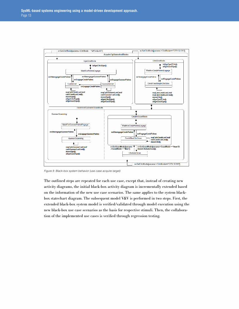
The next step in black-box use case analysis is the description of system-level, state-based behavior. The SysML artifact used for this is the statechart diagram (figure 9). Statecharts are hierarchical statemachines that visualize system states and modes and their changes as the response to external stimuli. The use case related state-based behavior is derived from the captured use case scenarios.
At this stage, the verification and validation (V&V) of the black-box use case model and the underlying requirements (i.e., operational contracts) can start. V&V is performed through model execution using the captured black-box use case scenarios as the basis for respective stimuli. It should be noted that, following the previously outlined key objectives of this process, the focus is on the analysis of the generated sequences rather than on the under-lying functionality.
So far, the use case model represents an error/fail-free (“sunny day”) behavior. At this stage, it may be extended regarding possible exceptions (“rainy day” behavior).
SysML-based systems engineering using a model-driven development approach. Page 13
Figure 9. Black-box system behavior (use case acquire target)
The outlined steps are repeated for each use case, except that, instead of creating new activity diagrams, the initial black-box activity diagram is incrementally extended based on the information of the new use case scenarios. The same applies to the system black-box statechart diagram. The subsequent model V&V is performed in two steps. First, the extended black-box system model is verified/validated through model execution using the new black-box use case scenarios as the basis for respective stimuli. Then, the collabora-tion of the implemented use cases is verified through regression testing.

SysML-based systems engineering using a model-driven development approach. Page 14
At the end of the functional analysis phase, a black-box system model is built of verified and validated operational contracts, representing the underlying functional requirements. The black-box system model is imported into the model/requirements repository, and the operational contracts are linked to the high-level system requirements. The black-box use case scenarios are imported into the test data repository for reuse in the subsequent architectural design phases.
Architectural design
System architectural design
The focus of the system architectural design phase is the allocation of the verified and validated operational contracts to a physical architecture. The allocation is an iterative process and is performed in collaboration with domain experts. Di!erent architectural concepts and allocation strategies may be analyzed, taking into consideration performance and safety requirements that were captured during the requirements analysis phase.
System architectural design starts with the definition of the physical subsystems. The SysML artifact used for this is the structure diagram. Constituents of this model are the actor blocks and the system block. Parts of the system block are the physical subsystems of the chosen architecture. In the case study, the system design consists of six physical subsystems (LRU = line replaceable unit, figure 11).
Figure 10. White-box scenario UCIWB21 (decomposed black-box scenario of figure 6)

SysML-based systems engineering using a model-driven development approach. Page 15
Next, the previously identified black-box operational contracts are allocated to the physi-cal subsystems using an activity diagram (white-box activity diagram). Essentially, this activity diagram is a copy of the black-box activity diagram. The only di!erence is that the system now is partitioned into swim lanes, each representing a physical subsystem. Based on the chosen design concept, the system operational contracts are “moved” to respective subsystem swim lanes. An essential precondition for this allocation is that the initial links (functional flow) between the operational contracts are maintained.
The white-box activity diagram is complemented by the definition of white-box sequence diagrams. White-box sequence diagrams are decompositions of the previously captured black-box sequence diagrams and are utilized to identify the interfaces of the physical subsystems. In white-box sequence diagrams, the system life-line is split into a set of subsystem lifelines. Based on the allocation defined in the white-box activity diagram, the subsystem operational contracts are placed on respective subsystem lifelines. In order to maintain the initial functional flow, service requests from one physical subsystem to the other may need to be generated. They define the interfaces between the subsystems.
In the example shown in figure 10, the implementation concept was that LRU1 was con-sidered the commander’s input/output (I/O) device. Most of the identified functionality had to be implemented in LRU5. The CITV control had to be in LRU6. In this scenario, LRU4 served as a gateway between LRU1 and LRU5. By mapping the use case scenario to the physical architecture, the links and the associated ports and interfaces are defined for each involved physical subsystem. For each physical subsystem, the associated state-based behavior is captured in a statechart diagram. These statechart diagrams will extend incre-mentally with each mapped use case scenario.

SysML-based systems engineering using a model-driven development approach. Page 16
The outlined process is performed iteratively for all black-box scenarios. Figure 11 shows the final result. Figure 12 depicts the chosen architectural design and resulting physical subsystem interfaces by means of an N-squared (N2) chart. An N2 chart is structured by locating the nodes of communication on the diagonal, resulting in an NxN matrix for a set of N nodes. For a given node, all outputs (SysML-required interfaces) are located in a row of that node, and inputs (SysML-provided interfaces) are in the column of that node.
The correctness and completeness of the system architecture model are checked through model execution. Once the model functionality is verified, the architectural design can be analyzed with regard to the performance and safety requirements. The analysis typically includes failure modes e!ects analysis (FMEA) and mission criticality analysis.
Figure 11. Activity operational contracts allowed to an LRU network architecture

SysML-based systems engineering using a model-driven development approach. Page 17
Figure 12. Documentation of physical subsystem interfaces by means of an N2 chart
Subsystem architectural design
This phase focuses on the implementation of the allocated operational contracts. Decisions are made as to which operational contracts in a physical subsystem should be implemented in hardware (e.g., mechanical or ASIC) and which should be implemented in software. For operational contracts that span more than one domain, further analysis will be needed. Subsystem domain experts may participate in this analysis.
Once the hardware/software design decisions are made, the workflow is similar to the one outlined in the system architectural design phase. In each white-box use case scenario, the physical subsystem lifelines are split into hardware and/or software lifelines, each repre-senting a subsystem component. Based on the chosen hardware/software design concept, operational contracts are placed on the respective subsystem component lifelines and the associated functional flow between subsystems and subsystem components established through respective service requests (figure 13). Thus, subsystem component ports and interfaces are defined. For each physical subsystem component, the associated state-based behavior is captured in a statechart diagram. These statechart diagrams will extend incrementally with each white-box use case scenario.

SysML-based systems engineering using a model-driven development approach. Page 18
The outlined process is performed iteratively for all white-box scenarios. The final deployment architecture is verified through regression testing.
At the end of the system architectural design phase, the deployment model is imported into the model/requirements repository, and the hardware/software assigned operational contracts are linked to the original requirements. For each physical subsystem, the follow-ing documents are generated from the deployment model as hand-o!s to the subsequent hardware and software design:
Hardware/software requirements specificationLogical interface control document (N2 chart)Subsystem/subsystem component test vectors derived from system-level use case scenarios
Figure 13. Subsystem architectural design: decomposition of LRU5 (WB scenario figure 10)

SysML-based systems engineering using a model-driven development approach. Page 19
Conclusion
This article demonstrated that SysML, a subset of UML 2.0, is the right approach to stan-dardize model-based, function-driven systems engineering. In the context of a common, paradigm-independent modeling language for both systems engineers and software engineers, SysML may be considered as a “dialect” of UML. Based on the preliminary specification of SysML (Rel. 0.98), an integrated systems/software development process could be defined allowing a seamless transition between the two domains.
For more information
To learn more, please visit:
www.telelogic.com

© Copyright IBM Corporation 2008
IBM Corporation Software Group Route 100 Somers, NY 10589 U.S.A.
Produced in the United States of America October 2008 All Rights Reserved
IBM, the IBM logo, ibm.com, Rational, and Telelogic are trademarks or registered trademarks of International Business Machines Corporation in the United States, other countries, or both. If these and other IBM trade-marked terms are marked on their first occurrence in this information with a trademark symbol (® or ™), these symbols indicate U.S. registered or common law trademarks owned by IBM at the time this information was published. Such trademarks may also be registered or com-mon law trademarks in other countries. A current list of IBM trademarks is available on the Web at “Copyright and trademark information” at ibm.com/legal/copytrade.shtml
Other company, product, or service names may be trademarks or service marks of others.
References in this publication to IBM products and services do not imply that IBM intends to make them available in all countries in which IBM operates.
The information contained in this documentation is provided for informational purposes only. While efforts were made to verify the completeness and accuracy of the information contained in this documentation, it is provided “as is” without war-ranty of any kind, express or implied. In addition, this information is based on IBM’s current product plans and strategy, which are subject to change by IBM without notice. IBM shall not be respon-sible for any damages arising out of the use of, or otherwise related to, this documentation or any other documentation. Nothing contained in this documentation is intended to, nor shall have the effect of, creating any warranties or representations from IBM (or its suppliers or licensors), or altering the terms and conditions of the applicable license agreement governing the use of IBM software.
RAW14055-USEN-004263_2_0810_US