system-10 btu meter dual network interface … · dual network interface installation guide (bacnet...
TRANSCRIPT

11451 Belcher Road South, Largo, FL 33773 • USA • Tel +1 (727) 447-6140 • Fax +1 (727) 442-5699www.onicon.com • [email protected]
SYSTEM-10 BTU METERInstallation and Operation Guide
For Software Version DM 1.0 and Higher
03-180651-23 / 18323
11451 Belcher Road South, Largo, FL 33773 • USA • Tel +1 (727) 447-6140 • Fax +1 (727) 442-5699 • [email protected] BTU Meter Manual 03/18 - 0651-23 / 18323 Page 2
SAFETY INFORMATION
This meter was calibrated at the factory before shipment. To ensure correct use of the meter, please read this manual thoroughly.
Regarding this Manual:
• This manual should be passed on to the end user. • Before use, read this manual thoroughly to comprehend its contents. • The contents of this manual may be changed without prior notice. • All rights reserved. No part of this manual may be reproduced in any form without ONICON’s written permission. • ONICON makes no warranty of any kind with regard to this material, including, but not limited to, implied warranties of merchantability and suitability for a particular purpose. • All reasonable effort has been made to ensure the accuracy of the contents of this manual. However, if any errors are found, please inform ONICON. • ONICON assumes no responsibilities for this product except as stated in the warranty. • If the customer or any third party is harmed by the use of this product, ONICON assumes no responsibility for any such harm owing to any defects in the product which were not predictable, or for any indirect damages.
Safety Precautions:
The following general safety precautions must be observed during all phases of installation, operation, service, and repair of this product. Failure to comply with these precautions or with specific WARNINGS given elsewhere in this manual violates safety standards of design, manufacture, and intended use of the product. ONICON Incorporated assumes no liability for the customer’s failure to comply with these requirements. If this product is used in a manner not specified in this manual, the protection provided by this product may be impaired.
The following symbols are used in this manual:
!
!
WARNING
Messages identified as “Warning” contain information regarding the personal safety of individuals involved in the installation, operation or service of this product.
CAUTION
Messages identified as “Caution” contain information regarding potential damage to the product or other ancillary products.
IMPORTANT NOTE
Messages identified as “Important Note” contain information critical to the proper operation of the product.
i

11451 Belcher Road South, Largo, FL 33773 • USA • Tel +1 (727) 447-6140 • Fax +1 (727) 442-5699 • [email protected] BTU Meter Manual 03/18 - 0651-23 / 18323 Page 3
TABLE OF CONTENTS1.0 INTRODUCTION ...................................................................................................... 5
1.1 PURPOSE OF THIS GUIDE ........................................................................... 5
1.2 TYPICAL SYSTEM-10 BTU METER ............................................................. 5
1.3 STANDARD FEATURES AND SPECIFICATIONS ........................................ 5
1.4 ADDITIONAL REQUIRED HARDWARE ....................................................... 7
1.5 WORKING ENVIRONMENT ......................................................................... 7
1.6 SERIAL NUMBER .......................................................................................... 7
2.0 UNPACKING ... .......................................................................................................... 8
2.1 CHECKING THAT YOU HAVE RECEIVED EVERYTHING .......................... 8
3.0 INSTALLATION ........................................................................................................ 9
3.1 SITE SELECTION ........................................................................................... 9
3.2 MECHANICAL INSTALLATION ................................................................. 10 3.2.1 Main Unit Installation .................................................................... 10 3.2.2 Thermowell Installation ................................................................ 11 3.2.2.1 Standard Thermowells ....................................................... 11 3.2.2.2 Hot Tap Thermowells ......................................................... 11 3.2.3 Temperature Sensor Installation ................................................... 13
3.2.4 Flow Meter Installation ................................................................. 14
3.3 ELECTRICAL INSTALLATION ................................................................... 15
3.3.1 Input Power ..................................................................................... 15
3.3.2 Input Signal Connections ............................................................... 18 3.3.2.1 Input Signal Connections from Temperature Sensors ...... 18 3.3.2.2 Input Signal Connections from Insertion Turbine Meters 19 3.3.2.3 Input Signal Connections from F-2500 Meters .................. 19 3.3.2.4 Input Signal Connections from F-2600 & F-2700 Meters .. 20 3.3.2.5 Input Signal Connections from F-3100 & F-3200 Meters .. 20 3.3.2.6 Input Signal Connections from F-3500 Meters .................. 21 3.3.2.7 Input Signal Connections from FB-3500 Meters ............... 21 3.3.2.8 Input Signal Connections from F-4200 Meters .................. 22 3.3.2.9 Input Signal Connections from F-4600 Meters .................. 23
3.3.3 Contact Closure Input for Flow Direction .............................................................. 24
3.3.4 Contact Closure Output for Energy Total(s) and Mode ................. 24
3.3.5 Isolated Analog Output(s) (Optional) ........................................... 25
4.0 SYSTEM-10 START-UP AND COMMISSIONING ................................................. 26
4.1 DISPLAY AND KEYPAD OPERATION ........................................................ 26
4.2 PROCESSOR START-UP .............................................................................. 26
4.3 UNITS AND MULTIPLIERS ......................................................................... 27
4.4 ANALOG OUTPUTS .................................................................................... 27
4.5 ENABLING / DISABLING FRONT PANEL RESET ...................................... 28
4.6 COMMISSIONING ........................................................................................ 29

11451 Belcher Road South, Largo, FL 33773 • USA • Tel +1 (727) 447-6140 • Fax +1 (727) 442-5699 • [email protected] BTU Meter Manual 03/18 - 0651-23 / 18323 Page 4
TABLE OF CONTENTS (CONTINUED)
5.0 DIAGNOSTICS ......................................................................................................... 32
5.1 DIAGNOSTICS .............................................................................................. 32 5.1.1 Diagnostic Lights ............................................................................ 32 5.1.2 Flow Test Signals ............................................................................ 32 5.1.3 Temperature Test Signals ............................................................... 33
5.2 ALARM STATUS MENU PAGE.................................................................... 33
5.3 TROUBLESHOOTING GUIDE FOR ONICON SYSTEM-10 BTU
MEASUREMENT SYSTEM .......................................................................... 34
APPENDIX A – DRAWINGS
A-1 TYPICAL SYSTEM-10 INSTALLATION
A-2 STANDARD THERMOWELL ASSEMBLY
A-3 THERMOWELL INSTALLATION
A-4/A-5 HOT TAP THERMOWELL (2 Pages)
A-6 OUTDOOR THERMOWELL ASSEMBLY
A-7/A-8 HEAVY DUTY THERMOWELL FOR HIGH TEMPERATURE / PRESSURE (2 Pages)
A-9 TEMPERATURE SENSOR ASSEMBLY
A-10 MOTHER BOARD TEMPERATURE SENSOR INPUT CONNECTIONS
A-11 MOTHER BOARD INSERTION TURBINE METER INPUT CONNECTIONS
A-12 MOTHER BOARD F-2500 VORTEX METER INPUT CONNECTIONS
A-13 MOTHER BOARD F-2600 & F-2700 VORTEX METER INPUT CONNECTIONS
A-14 MOTHER BOARD F-3100 & F-3200 ELECTROMAGNETIC INPUT CONNECTIONS
A-15 MOTHER BOARD F-3500 ELECTROMAGNETIC INPUT CONNECTIONS
A-16 MOTHER BOARD FB-3500 ELECTROMAGNETIC INPUT CONNECTIONS
A-17 SYSTEM-10 TO F-4200 FLOW METER INPUT CONNECTIONS
A-18 MOTHER BOARD
A-19 BTU COMPUTER BOARD
A-20 POWER SUPPLY BOARD
A-21 BTU METER ANALOG OUTPUT BOARD (with 1 analog output)
A-22 BTU METER ANALOG OUTPUTS BOARD (with 4 analog outputs)

11451 Belcher Road South, Largo, FL 33773 • USA • Tel +1 (727) 447-6140 • Fax +1 (727) 442-5699 • [email protected] BTU Meter Manual 03/18 - 0651-23 / 18323 Page 5
SECTION 1.0: INTRODUCTION
1.1 PURPOSE OF THIS GUIDE
The purpose of this guide is to provide installation and commissioning procedures and basic operating and servicing instructions for the ONICON SYSTEM-10 BTU Meter.
1.3 STANDARD FEATURES AND SPECIFICATIONS
• Single mode Btu calculations, in either the heating or cooling mode, are totalized, and displayed. • Two-pipe dual mode Btu calculations in both the heating mode and the cooling modes, are totalized and displayed. • Bi-directional dual mode Btu calculations are totalized and displayed.
! WARNING
Only qualified service personnel should attempt to install or service this product. Serious injury may result from the improper Installation or use of this product.
1.2 TYPICAL SYSTEM-10 BTU METER
ONICON’S System-10 is a true heat (Btu) computer, which accepts data from several sensors, performs a series of computations with that data, and displays and/or transmits the results as an indication of the amount of heat (Btu’s) being transferred per unit time or as a totalized amount.

11451 Belcher Road South, Largo, FL 33773 • USA • Tel +1 (727) 447-6140 • Fax +1 (727) 442-5699 • [email protected] BTU Meter Manual 03/18 - 0651-23 / 18323 Page 6
GENERAL SPECIFICATIONSCALIBRATION Flow meter and temperature sensors are individually calibrated, followed by a complete system calibration. Field commissioning is also available.
ACCURACY TEMPERATURE
Overall differential temperature measurement uncertainty of ≤ ± 0.15 °F over the stated range(Includes uncertainty associated with the sensors, transmitters, cabling and calculator input circuitry) Temperature sensors meet EN1434 / CSA C900.1 accuracy requirements for 1K sensors for cooling applications, 32 – 77 °FTemperature sensors meet EN1434 / CSAC900.1 accuracy requirements for 2K sensors for heating applications, 140 – 212 °F
CALCULATOR Computing nonlinearity within ±0.05% Calculator meets EN1434 / CSAC900.1 class 1 accuracy requirements for 2K sensors for all applications
TEMPERATURE SENSORS Solid-state sensors are custom calibrated using N.I.S.T. traceable temperature standards. Current based signal (mA) is unaffected by wire length.
PROGRAMMING Factory programmed for specific application.
MEMORY Nonvolatile EEPROM memory retains all program parameters and totalized values in the event of power loss.
DISPLAY Alphanumeric LCD displays total energy, total flow, energy rate, flow rate, supply temperature, return temperature. serial number and alarm status Alpha: 16 character, 0.2” high Numeric: 8 digit, 0.4” high Rate Display Range: 0 - 9,999,999 Total Display Range: 0 - 9,999,999 The totals will roll over to zero when the maximum count is exceeded.
OUTPUT SIGNALS Standard: Isolated solid-state dry contacts for energy total Maximum contact ratings: 100 mA, 50 VDC Contact duration: 0.5, 1, 2 or 6 seconds (factory selectable) Optional: Multiple isolated analog outputs for energy rate, flow rate, supply and return temperature and delta temperature (factory selectable) Output type: 4-20 mA, 0-10 V or 0-5 V (field selectable) Optional Interval Data Logging: This option provides up to 24 hours of rate and total data logging in 15 minute intervals. Data includes date/time stamp, measured value & scaling factors when appropriate. Network Interface Options: MODBUS RTU RS485 MODBUS RTU TCP/IP BACnet MS/TP BACnet UDP/IP LONworks FTT10A JCI Metasys - N2 Siemens Apogee - P1 FLN
ENVIRONMENTAL Ambient temperature range: -20° to 140° F (-29° to 60° C)
Altitude: Up to 6,561ft (2000m)Relative Humidity: Maximum relative humidity 80% at
88° F (31° C) decreasing linearly to 50% RH at 104° F(40° C)
Pollution Degree: 2
LIQUID FLOW SIGNAL INPUT Standard: 0-15 V pulse output from any ONICON flow meter Optional: 4 - 20 mA analog output from any flow meterTEMPERATURE RANGE Liquid temperature range: 25° to 200°F Ambient temperature range: -20° to 140° F
MAINTENANCE ONICON recommends periodic inspection and recalibration
for sensors connected to the System-10 BTU Meter. No other periodic maintenance is required for the main unit.
MECHANICAL ELECTRONICS ENCLOSURE: Standard: Steel NEMA 13, wall mount, 8”x 10”x 4” TEMPERATURE THERMOWELLS: Standard: ½” NPT brass thermowells (length varies with pipe size) with junction box Note: 6” pipes and larger require SS thermowell option Optional: • ½” NPT stainless steel thermowells • Outdoor junction box with thermal isolation • Hot tap thermowells for installations in a pressurized system with no shutdown
ELECTRICAL
This equipment is intended for INSTALLATION CATEGORY
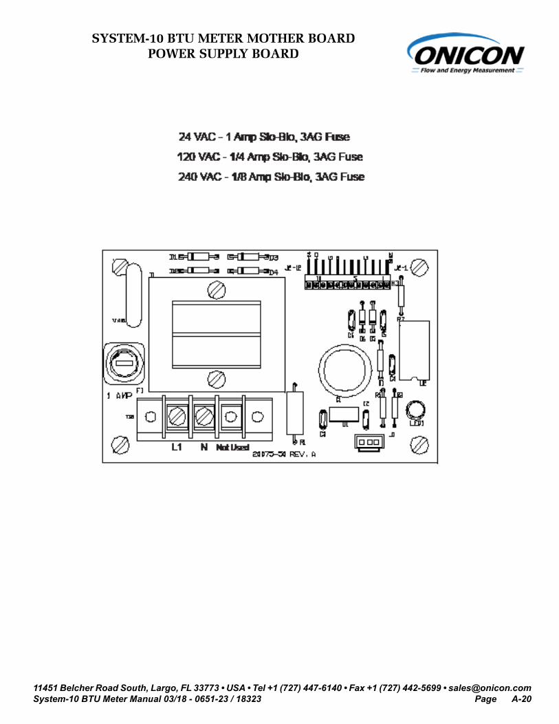
(OVERVOLTAGE CATEGORY) II applications. INPUT POWER: Factory Selectable: 24 VAC: 20 - 28V, 50/60 Hz, 500 mA 120 VAC: 108 - 132V, 50/60 Hz, 250 mA 240 VAC: 207 - 253V, 50 Hz, 250 mA INTERNAL FUSE RATING: 24 VAC - 1 Amp Slo-Blo, 3AG Fuse 120 VAC - 1/4 Amp Slo-Blo, 3AG Fuse 240 VAC - 1/8 Amp Slo-Blo, 3AG Fuse OUTPUT: 24 VDC, 250 mA maximum OVERCURRENT PROTECTIVE DEVICE RATINGS: Supply mains overcurrent protective devices with the following ratings: 120 VAC 50/60 Hz – 15 A 240 VAC 50 Hz – 6 A WIRING: Temperature signals: Use 18-22 ga twisted shielded pair Flow signals: Use 18-22 ga shielded cable – see flow meter specification sheet or flow meter manual for the correct number of conductors. 24 VAC input power: Use PVC jacketed copper cable with a wire gauge suitable for the length of run and required maximum current carrying capacity. The installation must comply with all local, state and federal building codes.
120/240 VAC input power: Use a three wire service with one wire a protective earth ground. The installation must comply with all local, state and federal building codes.
Note: Specifications are subject to change without notice.
! WARNING
All electrical connections must be made in accordance with the information provided here. Failure to do so will result in an increased risk of injury.

11451 Belcher Road South, Largo, FL 33773 • USA • Tel +1 (727) 447-6140 • Fax +1 (727) 442-5699 • [email protected] BTU Meter Manual 03/18 - 0651-23 / 18323 Page 7
1.4 ADDITIONAL REQUIRED HARDWARE
ONICON offers a wide variety of flow meters to satisfy most hydronic energy metering applications.
Model F-1100 Single Turbine Insertion Flow Meter For line sizes 1¼” and larger with 25 diameters of straight pipe run available for installation. (F-1100 can also be used with 1” copper lines.)
Model F-1200 Dual Turbine Insertion Flow Meter For line sizes 2½” and larger with 15 diameters of straight pipe run available for installation.
Model F-1300 Inline Turbine Flow Meter For line sizes ¾” and 1” with 25” of straight pipe run available for installation. Model F-3500 Insertion Electromagnetic Flow Meter For line sizes ¼” and larger. (See F-3500 manual for straight run requirements.)
Model FB-3500 Insertion Electromagnetic Flow Meter For bi-directional flow applications in line sizes 3” and larger. (See FB-3500 manual for straight run requirements.)
Model F-26** Inline Vortex Flow Meter (Suitable for use in higher temperature applications) For line sizes 1” through 12”. (See Vortex Flow Meter manual for straight run requirements.)
Model F-31** / F-32** Inline Electromagnetic Flow Meter For line sizes 1¼” and larger with 5 diameters of straight pipe run available for installation.
Model F-4200 Clamp-on Ultrasonic Flow Meter For line sizes ½” through 48” (See F-4200 Flow Meter manual for straight run requirements.) Please refer to ONICON’s flow meter literature, or contact ONICON for help in selecting the flow meter that will best fit your requirements.
1.5 WORKING ENVIRONMENT
The SYSTEM-10 was designed for installation and use in typical industrial environments that are free of corrosive liquids and fumes, direct liquid exposure, temperature extremes and vibrations. Do not expose the meter to direct sunlight.
The operating ambient air temperature range is -20° F to 140° F. The electrical power should be relatively clean, free of high frequency noise, large voltage transients, and protected from power surges and brown outs.
1.6 SERIAL NUMBER
Serial NumberThe serial number of your SYSTEM-10 is located outside and inside the main unit. All components of your SYSTEM-10 (flow meter, temperature sensors, and main unit) should bear identical serial numbers if ordered together. The serial numbers are unique identifiers that you should have available when contacting ONICON for assistance regarding your system.

11451 Belcher Road South, Largo, FL 33773 • USA • Tel +1 (727) 447-6140 • Fax +1 (727) 442-5699 • [email protected] BTU Meter Manual 03/18 - 0651-23 / 18323 Page 8
SECTION 2.0: UNPACKING
The SYSTEM-10 is generally shipped in one package unless optional hardware or equipment is ordered. (Thermowells may have been shipped in advance.) Notify the freight carrier and ONICON if any items are damaged in transit.
NOTE: Flow meters are packed separately.
2.1 CHECKING THAT YOU HAVE RECEIVED EVERYTHING
• Standard Documentation Enclosed with each SYSTEM-10 is a comprehensive documentation package that includes the following items:
The SYSTEM-10 BTU Meter Installation and Operation Guide The BTU Meter Certificate of Calibration Please notify ONICON if any of these items are missing.
i IMPORTANT NOTE
The ONICON System-10 BTU Measurement System is a custom calibrated system. Unless specifically noted in writing by ONICON, ALL COMPONENTS (Btu meter, flow meter, and temperature sensors) share the same serial number and must be installed together as a system. Mixing components from different systems will result in significant errors in calibration.
• The Main Unit Remove the SYSTEM-10 from the shipping carton and inspect it for physical damage. When you complete the external inspection, open the SYSTEM-10 main unit and remove the plastic bag containing the temperature sensors. Inside the main unit there are at least three circuit boards (the number may vary according to the options purchased). Ensure that the boards and connectors are securely plugged into the mother board (Appendix A-14). Please notify ONICON immediately if you find any discrepancies.
• Temperature Sensors Temperature sensors are shipped inside the main unit. Inspect the sensors and cables for external damage. Each sensor should have a label attached with a serial number identical to that found on the SYSTEM-10 main unit.
• Temperature Thermowells Note that thermowells and installation hardware are frequently shipped in advance of the meter(s). Otherwise, the standard thermowells and installation hardware are packed with the main unit. Optional hot tap thermowells will be shipped in a separate box.
• The Flow Meter The flow meter calibrated with this Btu meter came complete with an instruction manual. Please refer to the flow meter instruction manual for detailed information regarding the installation, commissioning, and operation of the flow meter. Each Btu meter is calibrated to a specific flow meter and must be used together as a system. If the flow meter and Btu meter were purchased together, the serial number on the flow meter should match the serial number on the label mounted directly on the Btu meter.

11451 Belcher Road South, Largo, FL 33773 • USA • Tel +1 (727) 447-6140 • Fax +1 (727) 442-5699 • [email protected] BTU Meter Manual 03/18 - 0651-23 / 18323 Page 9
SECTION 3.0: INSTALLATION
The SYSTEM-10 BTU Meter should be installed by experienced plumbers, electricians, and others with related knowledge and experience in the heating, cooling, and fluid metering fields. ONICON will be happy to assist with technical recommendations and to provide guidance by telephone and/or e-mail. On-site field engineering, installation, and service are also available at an additional cost. The installer should use good trade practices and must adhere to all state and local building, or other, applicable codes.
Before you begin, clean the external surfaces of all pipes at the installation sites so that they are free of debris, foreign matter, solids, leak inhibitors, and chemically aggressive substances. Flush the entire system so that it is free of flux, solder, pipe and tube cuttings and any other free moving particles.
3.1 SITE SELECTION
Careful attention to the site selection for the system components will help the installers with the initial installation, reduce start-up problems, and make future maintenance easier. For example, do not install the flow meter where it will be difficult for personnel to perform periodic maintenance. When selecting a site for mounting the system components, consider the criteria under Section 1.5: WORKING ENVIRONMENT, as well as the following:
i IMPORTANT NOTE
Proper site selection is critical to the performance of this Btu meter. Both the flow meter and the two temperature sensors must be properly located within the piping system in order to ensure an accurate energy measurement.
• The Main Unit Find an easily accessible location where wire connections can be made and meter readings can be taken from floor level. Mount the System-10 enclosure on a vibration free surface. Avoid locations such as the plenum of a fan coil, heat exchanger or any housing that may contain electric motors or other strong sources of electrical interference.
• The Flow Meter When properly installed, the flow meter will only measure flow associated with that portion of the piping system for which the energy measurement is being made. The flow meter may be installed in either the supply or return line. Choose the location with the longest straight run of unobstructed pipe. Please refer to the flow meter installation manual for specific information regarding the straight run requirements for the flow meter used with this SYSTEM-10 BTU Meter.
• The Temperature Sensors The two temperature sensors must be located in such a manner as to accurately measure only the temperature of the supply line entering and the return line leaving the portion of the piping system for which the energy measurement is being made. If possible, find an easily accessible location where wire connections can be made from floor level. This will facilitate any future service. Place the temperature sensors away from strong sources of electrical noise that might affect the performance of the sensors. One temperature sensor thermowell will need to be placed in the same pipe with the flow meter. It should be located on the downstream side of the flow meter. The downstream distance between the thermowell and flow meter should be at least five pipe diameters, leaving enough clearance to remove either sensor from the pipe without interference from the other sensor.

11451 Belcher Road South, Largo, FL 33773 • USA • Tel +1 (727) 447-6140 • Fax +1 (727) 442-5699 • [email protected] BTU Meter Manual 03/18 - 0651-23 / 18323 Page 10
3.2 MECHANICAL INSTALLATION
i
3.2.1 Main Unit Installation
• Find an easily accessible location where electrical connections can be made and meter readings can be taken from the floor level.
• Mount the Btu meter on a vibration-free surface. Avoid sites such as the plenum of a fan coil, heat exchanger, or other housings containing motors. Do not install the meter in direct sunlight.
Use four screws for mounting the Btu meter. The mounting surface must be structurally sound and capable of withstanding a minimum weight of 40lbs (18kg). Use the following screws for mounting.
• (4) Machine screws - HHMS .25-20 x 1.5”• (4) Wood screws - FHLS .25 x 1.5”• (4) Concrete screws - HHCS .25 x 1.5”
IMPORTANT NOTE
The ONICON System-10 BTU Measurement System is a custom calibrated system. Unless specifically noted in writing by ONICON, ALL COMPONENTS (Btu meter, flow meter and temperature sensors) share the same serial number and must be installed together as a system. Mixing components from different systems will result in significant errors in calibration.
! CAUTION
DO NOT drill holes in the enclosure. Use only the openings that are provided.

11451 Belcher Road South, Largo, FL 33773 • USA • Tel +1 (727) 447-6140 • Fax +1 (727) 442-5699 • [email protected] BTU Meter Manual 03/18 - 0651-23 / 18323 Page 11
3.2.2 Thermowell Installation
IMPORTANT NOTE
It is important that no dirt or other foreign material be allowed into the thermowells as this could affect the thermal response of the system.
i 3.2.2.1 Standard Thermowells
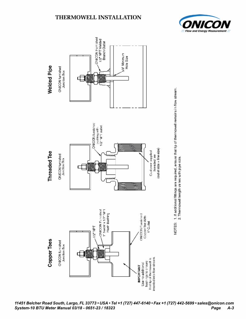
Standard thermowells are for new construction or scheduled shutdown. The most common installation methods are shown below. Refer to Appendix A-6 for thermal insulator installations and Appendix A-7 for high temperature (>300° F) thermowell installations. Consult ONICON for special applications.
NOTES: 1. Thermowell length varies with pipe size. 2. Use no additional bushings to ensure that tip of thermowell is inserted into flow stream.
3.2.2.2 Hot Tap Thermowells
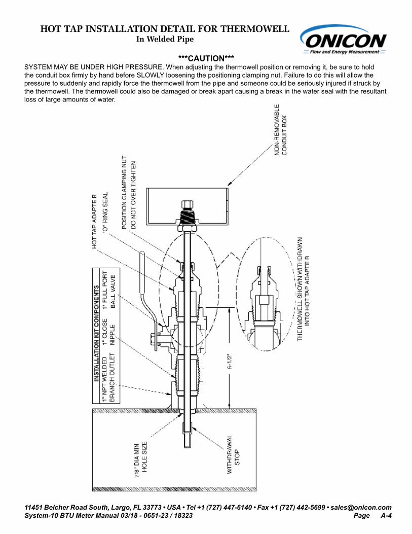
Hot tap thermowells are designed for retrofit applications where it is not practical to isolate and drain the pipe section prior to installation. The thermowell is installed through a 1” full port ball valve as shown in the drawing below. A wet tap drilling machine equipped with a 7/8” drill is required to perform this type of installation.
Install the valve assembly as shown in the drawing and then drill the 7/8” hole using the wet tap drilling machine. Once the valve assembly has been installed and the hole has been drilled, the thermowell can be inserted into the flow stream without a system shutdown.
!
WARNING
SYSTEM MAY BE UNDER HIGH PRESSURE. Be sure to hold the conduit box firmly by hand before slowly loosening the position clamping nut when installing, adjusting or removing the thermowell. Failure to do this will allow the pressure to suddenly and rapidly force the thermowell from the pipe, potentially causing serious injury. The thermowell could also be damaged or break apart causing a break in the water seal with the resultant loss of large amounts of water.
11451 Belcher Road South, Largo, FL 33773 • USA • Tel +1 (727) 447-6140 • Fax +1 (727) 442-5699 • [email protected] BTU Meter Manual 03/18 - 0651-23 / 18323 Page 12
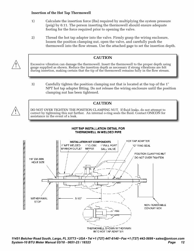
Insertion of the Hot Tap Thermowell
1) Calculate the insertion force (lbs) required by multiplying the system pressure (psig) by 0.11. The person inserting the thermowell should ensure adequate footing for the force required prior to opening the valve.
2) Thread the hot tap adapter into the valve. Firmly grasp the wiring enclosure, loosen the position clamping nut, open the valve, and carefully push the thermowell into the flow stream. Use the attached gage to set the insertion depth.
!
! CAUTION
Excessive vibration can damage the thermowell. Insert the thermowell to the proper depth using gauge supplied as shown. Reduce the insertion depth as necessary if strong vibrations are felt during insertion, making certain that the tip of the thermowell remains fully in the flow stream.
3) Carefully tighten the position clamping nut that is located at the top of the 1" NPT hot tap adapter fitting. Do not release the wiring enclosure until the position clamping nut has been tightened.
CAUTION
DO NOT OVER TIGHTEN THE POSITION CLAMPING NUT. If fluid leaks, do not attempt to correct by tightening this nut further. An internal o-ring seals the fluid. Contact ONICON for assistance in the event of a leak.

11451 Belcher Road South, Largo, FL 33773 • USA • Tel +1 (727) 447-6140 • Fax +1 (727) 442-5699 • [email protected] BTU Meter Manual 03/18 - 0651-23 / 18323 Page 13
Removal of the Hot Tap Thermowell
i
1) System pressure will try to push the thermowell out of the flow stream when the clamping nut is released. Be sure to establish safe footing prior to loosening the clamping nut. The force pushing out against the thermowell is the same as the insertion force calculated above.
2) Grasp the wiring enclosure firmly, holding the thermowell in the pipe and then loosen the position clamping nut. Slowly withdraw the thermowell from the pipe. After the thermowell is completely withdrawn, carefully close the isolation valve.
3.2.3 Temperature Sensor Installation
The temperature sensors are factory matched and tagged by serial number to a specific Btu meter. They are also labeled as SUPPLY and RETURN temperature sensors. Please consult ONICON before attempting to use any other temperature sensor.
Apply a thin coat of thermal compound to the temperature sensor, and gently insert the temperature sensor all the way into the thermowell until it contacts the bottom of the cavity. Gently tighten the retainer nut. DO NOT OVER TIGHTEN. The thermowell completely seals the plumbing system without the retainer nut. The only purpose for the nut is to keep the sensor from losing contact with the bottom of the thermowell cavity.
i
! WARNING
Maintain a firm hold on the wiring enclosure until the thermowell is completely withdrawn and the valve is closed.
IMPORTANT NOTE
Rotating the thermowell as you slowly withdraw it through the valve will ensure that the lower tip is fully withdrawn and completely free of the valve. If resistance is felt when closing the valve, open valve fully and rotate the well as you pull it further out of the pipe.
IMPORTANT NOTE
Cable length is specified at time of order. Cable provided for temperature sensors is #22 gauge twisted shielded pair. Additional cable may be added in the field if necessary, but must be of twisted shielded pair construction. (#22 gauge minimum and #18 gauge maximum)

11451 Belcher Road South, Largo, FL 33773 • USA • Tel +1 (727) 447-6140 • Fax +1 (727) 442-5699 • [email protected] BTU Meter Manual 03/18 - 0651-23 / 18323 Page 14
ONICON TEMPERATURE SENSOR
TEMPERATURE SENSOR INSTALLED IN THERMOWELL
RETAINING NUT(Do not overtighten)
3.2.4 Flow Meter Installation
Determine which pipe (supply or return) has the longer unobstructed straight run. Install the flow meter in the longest straight pipe run available. One temperature sensor can be installed five diameters downstream of the flow meter leaving enough clearance to remove either sensor from the pipe without interference from the other sensor.
Also refer to the installation manual and/or other documentation that is provided with your ONICON flow meter.
For F-1300 series inline turbine flow meters, refer to the documentation that is provided with the flow meter.
11451 Belcher Road South, Largo, FL 33773 • USA • Tel +1 (727) 447-6140 • Fax +1 (727) 442-5699 • [email protected] BTU Meter Manual 03/18 - 0651-23 / 18323 Page 15
3.3 ELECTRICAL INSTALLATION
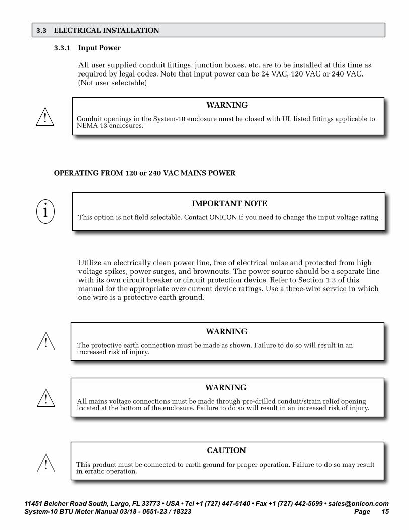
3.3.1 Input Power
All user supplied conduit fittings, junction boxes, etc. are to be installed at this time as required by legal codes. Note that input power can be 24 VAC, 120 VAC or 240 VAC. (Not user selectable)
OPERATING FROM 120 or 240 VAC MAINS POWER
Utilize an electrically clean power line, free of electrical noise and protected from high voltage spikes, power surges, and brownouts. The power source should be a separate line with its own circuit breaker or circuit protection device. Refer to Section 1.3 of this manual for the appropriate over current device ratings. Use a three-wire service in which one wire is a protective earth ground.
! WARNING
Conduit openings in the System-10 enclosure must be closed with UL listed fittings applicable to NEMA 13 enclosures.
!
!
!
WARNING
The protective earth connection must be made as shown. Failure to do so will result in an increased risk of injury.
WARNING
All mains voltage connections must be made through pre-drilled conduit/strain relief opening located at the bottom of the enclosure. Failure to do so will result in an increased risk of injury.
CAUTION
This product must be connected to earth ground for proper operation. Failure to do so may result in erratic operation.
i IMPORTANT NOTE
This option is not field selectable. Contact ONICON if you need to change the input voltage rating.

11451 Belcher Road South, Largo, FL 33773 • USA • Tel +1 (727) 447-6140 • Fax +1 (727) 442-5699 • [email protected] BTU Meter Manual 03/18 - 0651-23 / 18323 Page 16
Connect the power source to the main unit through the conduit opening located on the bottom of the main unit. Fasten the power wires to the appropriate screw terminals as shown. Do not exceed 12 in-lb (1.4 Nm) of torque when tightening.
As power is initially applied to the System-10, immediately confirm that the display is illuminated and scrolling through the character diagnostic test. The test will begin by indicating the letter P in every position followed by a countdown from 9 to 0 for each digit, If this does not occur, disconnect power immediately and re-verify all wiring connections. If the problem persists, contact ONICON.
WARNING
Disconnect main power before proceeding.!
! WARNING
Connect the protective earth wire to the lug located in the lower left hand corner of the motherboard.
Protective Earth Ground

11451 Belcher Road South, Largo, FL 33773 • USA • Tel +1 (727) 447-6140 • Fax +1 (727) 442-5699 • [email protected] BTU Meter Manual 03/18 - 0651-23 / 18323 Page 17
OPERATING FROM 24 VAC POWER
IMPORTANT NOTE
This option is not field selectable. Contact ONICON if you need to change the input voltage rating.
i
The SYSTEM-10 BTU Meter can be configured to operate from 24 ±4 V 50/60 Hz power. Connect the 24 volt power source to the System-10 using the pre-drilled conduit or strain relief opening located at the bottom of the enclosure. Do not connect the 24 volt source until all signal connections have been made and verified. Connect 24 VAC wires to the appropriate screw terminals as shown. Connect the protective earth wire as shown. Do not exceed 12 in-lb (1.4 Nm) of torque when tightening.
As power is initially applied to the System-10, immediately confirm that the power light is illuminated and the display is scrolling through the character diagnostic test. The test will begin by indicating the letter P in every position followed by a countdown from 9 to 0 for each digit. If this does not occur, disconnect power immediately and re-verify all wiring connections. Contact ONICON if the problem persists.
! CAUTION
This product must be connected to earth ground for proper operation. Failure to do so may result in erratic operation.
Protective Earth Ground

11451 Belcher Road South, Largo, FL 33773 • USA • Tel +1 (727) 447-6140 • Fax +1 (727) 442-5699 • [email protected] BTU Meter Manual 03/18 - 0651-23 / 18323 Page 18
3.3.2 Input Signal Connections
Make connections on the mother board, located in the main unit, at terminal strips T3, T4 and T5. Do not exceed 4.5 in-lb (0.5 Nm) of torque when tightening.
3.3.2.1 Input Signal Connections from Temperature Sensors
! CAUTION
Shield connections are required for proper operation. Failure to use shielded cable may result in erratic operation.

11451 Belcher Road South, Largo, FL 33773 • USA • Tel +1 (727) 447-6140 • Fax +1 (727) 442-5699 • [email protected] BTU Meter Manual 03/18 - 0651-23 / 18323 Page 19
3.3.2.2 Input Signal Connections From Turbine Flow Meters
ONICON turbine flow meters are provided with a number of different output configurations. These affect the number of wires contained in the cable attached to the flow meter. Refer to the diagram below and the laminated tag attached to the flow meter for specific details.
3.3.2.3 Input Signal Connections From F-2500 Flow Meters
Flow Meter Inputs
Flow Meter Inputs

11451 Belcher Road South, Largo, FL 33773 • USA • Tel +1 (727) 447-6140 • Fax +1 (727) 442-5699 • [email protected] BTU Meter Manual 03/18 - 0651-23 / 18323 Page 20
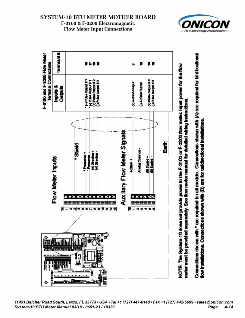
3.3.2.5 Input Signal Connections from F-3100 & F-3200 Flow Meter
CAUTION
Shield and earth connections are required for proper operation. Failure to use shielded cable or to connect earth to both the flow meter and System-10 may result in erratic operation. Shields should be terminated at the System-10 shield terminals and left unterminated at the flow meter.
!
CAUTION
The System-10 internal 24 V power supply cannot provide power to the F-3100 or F-3200 flow meters.!
3.3.2.4 Input Signal Connections From F-2600 & F-2700 Flow MetersFlow Meter Inputs

11451 Belcher Road South, Largo, FL 33773 • USA • Tel +1 (727) 447-6140 • Fax +1 (727) 442-5699 • [email protected] BTU Meter Manual 03/18 - 0651-23 / 18323 Page 21
3.3.2.7 Input Signal Connections from FB-3500 Flow Meter
! CAUTION
See FB-3500 installation and operation guide for additional information on properly grounding the meter.
3.3.2.6 Input Signal Connections from F-3500 Flow Meter
! CAUTION
See F-3500 installation and operation guide for additional information on properly grounding the meter.

11451 Belcher Road South, Largo, FL 33773 • USA • Tel +1 (727) 447-6140 • Fax +1 (727) 442-5699 • [email protected] BTU Meter Manual 03/18 - 0651-23 / 18323 Page 22
CAUTION
Shield and earth connections are required for proper operation. Failure to use shielded cable or to connect earth to both the flow meter and System-10 may result in erratic operation. Shields should be terminated at the System-10 shield terminals and left unterminated at the flow meter.
!
WARNING
Turn off mains power at the source prior to making power connections to the F-4000. Contact with exposed live wiring may result in electric shock, burns and/or serious injury.!
IMPORTANT NOTEDC powered version of the F-4200!
System-10 F-4200Flow Meter Connections
3.3.2.8 Input Signal Connections from F-4200 Flow Meter

11451 Belcher Road South, Largo, FL 33773 • USA • Tel +1 (727) 447-6140 • Fax +1 (727) 442-5699 • [email protected] BTU Meter Manual 03/18 - 0651-23 / 18323 Page 23
3.3.2.9 Input Signal Connections From F-4600 Flow Meter
Flow Meter Inputs

11451 Belcher Road South, Largo, FL 33773 • USA • Tel +1 (727) 447-6140 • Fax +1 (727) 442-5699 • [email protected] BTU Meter Manual 03/18 - 0651-23 / 18323 Page 24
3.3.3 Contact Closure Input For Flow Direction
The System-10 is provided with a separate input for determining flow direction. Connections for this input are made at T4 terminals 8 (+) and 9 (-). This input can be connected to a non-polarized contact closure relay or an open connector output. Note that the input is polarized for sinking (NPN) open collector outputs. Totals will accumulate in the mode 1 registers whenever the contacts are closed.
3.3.4 Contact Closure Output For Energy Total(s) And Mode Status
For single mode applications (heating or cooling), the output relay for energy total is located on the mother board at T1, pins 1 and 2. The value of each “closure” is listed on the certificate of calibration and is the same as the energy total multiplier displayed on the LCD (example: each closure = 10,000 Btu’s).
For dual mode applications (two-pipe heat/cool), the energy total for the heating mode (where supply temp is greater than return temp) is provided at T1, pins 1 and 2. The energy total in the cooling mode is provided at T1, pins 3 and 4. Mode status is at T1, pins 5 and 6 (open contact = mode 1 operation).
For bi-directional applications, the table below describes the relationship between mode 1 and mode 2 totals and forward and reverse flow for ONICON insertion turbine and inline electromagnetic flow meters.
Do not exceed 4.5 in-lb (0.5 Nm) of torque when tightening the terminals.
FLOW METER MODEL
FLOW DIRECTION RELATIVE TO
DIRECTION ARROW ON METER
FLOW METER OUTPUT
CONDITION
SYSTEM-10 MODE STATUS INDICATOR
(T1 - PINS 5 & 6)
SYSTEM-10 REGISTER ACCUMULATING
TOTALS
FB-3500 Series
Flow in the direction of arrow Closed contact Open contact Mode 1
Flow reverse from direction arrow Open contact Closed contact Mode 2
F-3000 SeriesInline
Flow Meter
Flow toward (+) signNot energized
(open)Closed contact Mode 2
Flow toward (-) signEnergized(closed)
Open contact Mode 1
11451 Belcher Road South, Largo, FL 33773 • USA • Tel +1 (727) 447-6140 • Fax +1 (727) 442-5699 • [email protected] BTU Meter Manual 03/18 - 0651-23 / 18323 Page 25
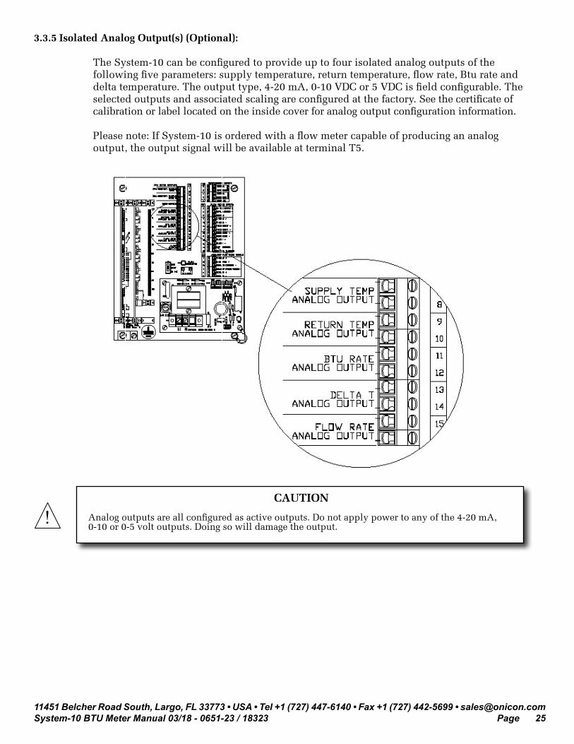
3.3.5 Isolated Analog Output(s) (Optional):
The System-10 can be configured to provide up to four isolated analog outputs of the following five parameters: supply temperature, return temperature, flow rate, Btu rate and delta temperature. The output type, 4-20 mA, 0-10 VDC or 5 VDC is field configurable. The selected outputs and associated scaling are configured at the factory. See the certificate of calibration or label located on the inside cover for analog output configuration information.
Please note: If System-10 is ordered with a flow meter capable of producing an analog output, the output signal will be available at terminal T5.
! CAUTION
Analog outputs are all configured as active outputs. Do not apply power to any of the 4-20 mA, 0-10 or 0-5 volt outputs. Doing so will damage the output.

11451 Belcher Road South, Largo, FL 33773 • USA • Tel +1 (727) 447-6140 • Fax +1 (727) 442-5699 • [email protected] BTU Meter Manual 03/18 - 0651-23 / 18323 Page 26
SECTION 4.0: SYSTEM-10 START-UP AND COMMISSIONING
4.1 DISPLAY AND KEYPAD
The display contains two lines of alphanumeric characters. The first line displays the current value. The second line contains the engineering units and a multiplier which can range from 1 to 1,000,000. The multiplier is the value the number on the top line must be multiplied by to achieve the correct value.
Three membrane keys are provided to operate the display and program the meter.
When operating in the run mode, the SCROLL button advances the display from one page to the next. A total of up to 11 different pages may be available for display depending whether the meter is operating in the single or dual mode.
The RESET button (if enabled) allows totals to be reset to zero. The PROGRAM button is not active when operating in the run mode.
4.2 PROCESSOR START-UP
When power is applied to the Btu meter alphanumeric characters appear on the two lines of the display indicating the meter is operating. Press and release the SCROLL button on the front panel. Observe the display cycle to the next display page.
Select the SUPPLY TEMP Page. Note the displayed temperature. Confirm that it is in the expected range. Now select the RETURN TEMP page. Again note the displayed temperature. Confirm that it is also in the correct range.
Select the FLOW RATE page. Note the displayed flow rate. Confirm that the flow rate value is in the correct range.
Successively pressing the SCROLL button will cycle the display through the run mode pages summarized in the tables on the next page.
To finalize the installation, follow the procedure outlined in section 4.5 to identify and designate the flow meter location.

11451 Belcher Road South, Largo, FL 33773 • USA • Tel +1 (727) 447-6140 • Fax +1 (727) 442-5699 • [email protected] BTU Meter Manual 03/18 - 0651-23 / 18323 Page 27
SINGLE MODE OPERATION
PAGE NUMBER DISPLAY NAME SELECTABLE UNITS1 ENERGY TOTAL BTU, TONHR or KWHR2 FLOW TOTAL GAL, LITER, METERS3
3 ENERGY RATE BTU/HR, TONS, KW4
FLOW RATEGPM, GPH, MGD, L/SEC, L/MIN,
L/HR, METERS3/HR5 SUPPLY TEMPERATURE DEG F, DEG C6 RETURN TEMPERATURE DEG F, DEG C
7* Di3 PULSE TOTAL COUNTS or TEXT ENTRY8 ALARM STATUS NOT APPLICABLE9 SERIAL NUMBER NOT APPLICABLE
DUAL MODE OR BI-DIRECTIONAL MODE OPERATION
PAGE NUMBER DISPLAY NAME SELECTABLE UNITS1 MODE 1 ENERGY TOTAL BTU, TONHR or KWHR2 MODE 1 FLOW TOTAL GAL, LITER,METERS3
3 MODE 2 ENERGY TOTAL BTU, TONHR or KWHR4 MODE 2 FLOW TOTAL GAL, LITER, METERS3
5 ENERGY RATE BTU/HR, TONS, KW6
FLOW RATEGPM, GPH, MGD, L/SEC, L/MIN,
L/HR, METERS3/HR7 SUPPLY TEMPERATURE DEG F, DEG C8 RETURN TEMPERATURE DEG F, DEG C
9* Di3 PULSE TOTAL COUNTS or TEXT ENTRY10 ALARM STATUS NOT APPLICABLE11 SERIAL NUMBER NOT APPLICABLE
* Menu page only displayed when optional digital input is present.
4.3 UNITS AND MULTIPLIERS
The units and multipliers are programmed prior to delivery. Contact ONICON for assistance in changing units or multipliers.
4.4 ANALOG OUTPUTS
The System-10 BTU Meter is capable of providing up to four analog outputs (optional). Analog outputs are programmed at the factory in terms of units and scaling. Changing any of the displayed units or multipliers will affect the analog outputs. If any unit or multiplier values are changed at the System-10 BTU Meter, the analog output value(s) will also be changed. If you are unsure of the ramifications of any changes you are contemplating, please contact ONICON for assistance.

11451 Belcher Road South, Largo, FL 33773 • USA • Tel +1 (727) 447-6140 • Fax +1 (727) 442-5699 • [email protected] BTU Meter Manual 03/18 - 0651-23 / 18323 Page 28
4.5 SELECTING THE FLOW METER LOCATION & ENABLING/DISABLING FRONT PANEL RESET
Before the System-10 is commissioned, the flow meter location should be programmed into the meter. This is particularly important for systems that will operate with delta temperatures ≥20 °F. The default setting for the flow meter location is unknown. It should be changed to the location setting that corresponds to the flow meter’s physical location in the piping system. Choose supply when the flow meter is located in the pipe leading to the inlet to the heat exchanger and return when the flow meter is located in the pipe leaving the outlet of the heat exchanger. Leave the setting at unknown for bi-directional flow applications.
The table below explains how to designate the flow meter location and how to enable or disable the front panel reset.
STEP ACTION REACTION COMMENT1 With the Btu meter running,
open the front panel and locate DEV ADD/PROG ENAB. Press DEV ADD/PROG ENAB and then release it.
None. DEV ADD/PROG ENAB is located in the lower left corner of the Btu computer board. (see appendix page A-14.)
2 Close the front panel.
3 Press the PROGRAM button. (If you do not press the PROGRAM button, the meter will revert to the run mode after 5 minutes.)
The Btu meter changes to program mode and the DEVICE ID page will appear with the first digit of the address flashing.
The PROGRAM button is on the front panel.
4 Press the PROGRAM button. The FM LOCN page appears with UNKNWN defaulted as the current location.
The PROGRAM button is on the front panel.
5 Press the SCROLL button. The setting will toggle between UNKNWN, SUPPLY, and RETURN.
Choose the FM LOCN as necessary.
6 Press the PROGRAM button. The FRONT PANEL RESET page appears with the N or Y flashing.
The PROGRAM button is on the front panel.
7 Press the SCROLL button. The setting will toggle between N and Y.
Enable or disable the FRONT PANEL RESET as necessary.
8 Press the PROGRAM button. The SAVE CHANGES page appears with the N flashing.
The new FRONT PANEL RESET setting must be saved to take effect.
9 Press the SCROLL button. The N changes to Y. The Y must be selected for the new address to take effect.
10 Press the PROGRAM button. The new setting is saved and the display reverts to the run mode.
The PROGRAM button is on the front panel.

11451 Belcher Road South, Largo, FL 33773 • USA • Tel +1 (727) 447-6140 • Fax +1 (727) 442-5699 • [email protected] BTU Meter Manual 03/18 - 0651-23 / 18323 Page 29
4.6 COMMISSIONING
Upon initial installation, it is strongly recommended that both the System-10 and its associated flow meter be commissioned to ensure that they are properly installed and functioning correctly. This process involves verifying the mechanical installation, measuring flow and temperature signals and then comparing these measurements to the specified installation and operating parameters listed on the certificate of calibration provided with the meter. The data collected during this initial commissioning process will then serve as baseline data for periodic revalidation of the meter operation.
COMMISSIONING PROCEDURE - ONICON BTU METERS
Please read all installation instructions carefully before proceeding. Wiring diagrams are located in the appendix of this manual. Use the Btu meter certificate of calibration to verify that the specified installation & operating parameters match the actual conditions at the location where the meter is installed. A worksheet for checking off these steps and recording measured values is located on the following page.
1. Confirm flow meter location and adequate straight pipe run to achieve desired results.
Confirm that the flow meter location is identified and selected as per section 4.5 of this manual.
Is the flow meter located in the correct location as required by the plans?
Compare actual straight pipe upstream and downstream of the flow meter location to the recommended distances identified in the flow meter installation manual. Note: The flow meter manual is very conservative, assuming worst-case pipe obstructions. Contact ONICON to discuss specifics of your application. If straight pipe run is very short, consult ONICON PRIOR to installing the flow meter to discuss the possibility of upgrading to a different flow meter.
Review and record the flow meter location program setting.
2. Confirm pipe size & material.
Confirm that the flow meter is tagged for the pipe diameter and material it is installed in and that this information corresponds to the information listed on the Btu meter certificate of calibration. When in doubt, measure the circumference of the pipe.
Pipe O.D. = (circumference / 3.14) – (insulation thickness x 2)
3. Confirm insertion depth and orientation (for insertion meters only).
Each insertion type flow meter comes with an attached insertion gage and instruction tag. Ensure that meter is inserted to correct depth and that the electronics enclosure is parallel with the pipe, with the arrow in the direction of flow.
4. Confirm temperature sensor thermowell installations.
Confirm that the thermowells are properly installed and the bottom of the well is in the flow stream. Make certain that only the components supplied with the installation kit were used and that additional bushings were not added.
5. Confirm temperature sensor installations.
Confirm that the temperature sensors are properly installed, and each sensor is bottomed out in the well. A small amount of thermal compound should be applied to the tip of each sensor to improve the thermal transfer.
Each sensor has a black sleeve on the cable coming up from the metal sensor. This sleeve in cut to length for the thermowell. When the sensor is fully bottomed out in the well, the retaining nut can be tightened without any of the black sleeve protruding through the nut.
6. Confirm connection to correct ONICON Btu meter.
Confirm that the flow meter serial number matches the Btu meter serial number (when ordered together). Also confirm that the serial numbers of the temperature sensors match the Btu and flow meters.

11451 Belcher Road South, Largo, FL 33773 • USA • Tel +1 (727) 447-6140 • Fax +1 (727) 442-5699 • [email protected] BTU Meter Manual 03/18 - 0651-23 / 18323 Page 30
7. Verify the type of fluid used in the piping system.
Confirm that the fluid specified on the Btu meter certificate of calibration matches the fluid flowing in the piping system.
8. Confirm correct supply voltage.
Verify that correct AC voltage is available at the power supply input terminals. System-10 BTU Meters are configured to operate from 24, 120 or 230 VAC input voltage (not field selectable).
Input voltages should be within the following ranges: 24 VAC: 20 - 28 VAC 120 VAC: 108 - 132 VAC 240 VAC: 207 - 253 VAC
The System-10’s internal power supply will provide 24 VDC to power the ONICON flow meter (except F-3100/F-3200) which can be measured at T-4, pins 1 (+) and 2 (-).
9. Verify flow meter and temp sensor wiring
Verify that the flow meter and temperature sensors are properly connected to the BTU meter. Consult the wiring diagram for your specific flow meter in the System-10 Installation Manual.
10. Verify that the flow test switch is in the RUN position.
Confirm that the flow test switch is in the correct position. The flow test switch is located in the middle of the motherboard immediately above the power supply board. The switch must be set to RUN for normal operation.
In order to proceed with the following steps, the Btu meter must be operating and connected to the network. There must also be flow in pipes. Flow signal readings should be taken while holding the flow rate constant if possible. Otherwise, take the various output readings as quickly as possible.
11. Select the SUPPLY TEMP page. Note and record the temperature.
Scroll through the Btu meter display pages and select the SUPPLY TEMP page. Note the displayed temperature and confirm that it is close to the design supply temperature specified on the Btu meter certificate of calibration. Record the temperature.
12. Select the RETURN TEMP page. Note and record the temperature.
Scroll through the Btu meter display pages and select the RETURN TEMP page. Note the displayed temperature and confirm that it is close to the design return temperature specified on the Btu meter certificate of calibration. Record the temperature.
13. Select the FLOW RATE page. Note and record the flow reading.
Scroll through the Btu meter display pages and select the FLOW RATE page. Note the displayed flow rate and confirm that it is within the expected range specified on the Btu meter certificate of calibration. Record the flow rate.
14 Note and record the ENERGY RATE.
Scroll through the Btu meter display pages and select the ENERGY RATE page. Note the displayed energy rate and confirm that it appears to be correct. For water, Btu/hr is approximately = 500 * Delta-T * GPM. Divide Btu/hr by 12,000 to convert to tons.
15. For flow meters that provide a frequency output, measure and record output(s). Compare calculated vs. displayed flow rates.
F-1200Confirm both turbines produce pulses.
The average frequency output signal is a 0-15 VDC pulsed output ranging up to 200 Hz and must be measured with a frequency counter or oscilloscope. Measure DC Frequency (Hz) at T4 from terminal 6(+) to 7(-).
GPM = Frequency in Hz x 60 Meter Factor in ppg.
(Refer to calibration tag for meter factor.)
For the F-1200 dual turbine model, also measure and record the top and bottom turbine signals.Top Turbine: T4-12(+) to T4-2(-). Bottom Turbine: T4-13(+) to T4-2(-)
Also, measure DC volts on same terminals. Five to 7 VDC is normal for a spinning turbine. Zero or 14+ VDC indicates a stopped turbine. (1 to 4 VDC could indicate a problem.)
16. Compare and record the displayed values with those shown by the building control system.
Scroll through each page of the Btu meter display menu and compare the displayed values with those shown on the building control network. Record the results.
End of standard commissioning. Please contact ONICON at (727)447-6140 with any questions.

11451 Belcher Road South, Largo, FL 33773 • USA • Tel +1 (727) 447-6140 • Fax +1 (727) 442-5699 • [email protected] BTU Meter Manual 03/18 - 0651-23 / 18323 Page 31
COMMISSIONING WORKSHEET - ONICON BTU METERS
Please read all installation instructions carefully prior to proceeding with these steps. Wiring diagrams are located in the appendix. Use the following worksheet for checking off the commissioning steps and recording measured values:
STEP TEST/MEASUREMENT S/N: S/N: S/N: S/N:
1. Meter location
1a. Supply/Return/Unknown
2. Pipe size
3. Insertion depth and orientation
4. Thermowell installation
5. Temperature installation
6. Match Btu meter, flow meter and temperature sensor serial numbers.
7. Verify the liquid type
8. Supply voltage verified (Note voltage.)
9. Verify flow meter and temp sensor wiring
10. Flow test switch position verified
In order to proceed with the following steps, the Btu meter must be operating and connected to the network. There must also be flow in pipes. Flow signal readings should be taken while holding the flow rate constant if possible. Otherwise, take the various output readings as quickly as possible.
11. Note and record the SUPPLY temperature.
12. Note and record the RETURN temperature.
13. Note and record the FLOW RATE.
14. Note and record the ENERGY RATE.
15. Frequency output(s): Avg = green, Top = whiteBottom = orange
Avg Freq. (HZ):
Avg Freq. (VDC):
Top Turbine (HZ):
Top Turbine (VDC):
Bottom Turbine (HZ):
Bottom Turbine (VDC):
Calculated Flow Rate:
16. Compare and record the displayed values with those shown on Btu meter certificate of calibration and the network, where appropriate.

11451 Belcher Road South, Largo, FL 33773 • USA • Tel +1 (727) 447-6140 • Fax +1 (727) 442-5699 • [email protected] BTU Meter Manual 03/18 - 0651-23 / 18323 Page 32
SECTION 5.0: DIAGNOSTICS
5.1 DIAGNOSTICS
The ONICON System-10 BTU Meter uses a microprocessor to calculate energy. Factory programmed settings provide rate and total values in accordance with the customer’s application data. Refer to the Btu meter certificate of calibration for a complete listing of factory settings. These settings may be reviewed and changed with assistance from ONICON.
The System-10 BTU Meter is also equipped with diagnostic indicator lights and self diagnostic test signals that confirm the operation of the microprocessor and its input circuitry. Please contact ONICON if any of the diagnostic lights or test signals listed below indicates a potential problem with the operation of the Btu meter.
5.1.1 Diagnostic Lights
Low Voltage Power Supply Located on the power supply board inside the System-10 BTU Meter (refer to A-15), is a single LEDs that will illuminate when +15 VDC is present.
Liquid Flow Located in the center of the motherboard (refer to A-12) next to terminal block T5, the LED will flash at a rate that is proportional to the liquid flow rate for frequency flow signals. For 4 - 20 mA signals, the light will stay lit whenever the output is greater than 4 mA. An unlit LED indicates no flow signal. 5.1.2 Flow Test Signals
Flow Test Located in the center of the motherboard (Refer to A-13) immediately above the power supply board is a three position slide switch used to test the flow input. When the switch is in the top position, the Btu meter input is connected to the flow meter. When the switch is in the middle position, the Btu meter input is connected to two test terminals used to apply a variable frequency to simulate flow. When the switch is in the bottom position, the Btu meter input is connected to a 50/60 Hz signal that simulates a fixed flow rate. Refer to the Btu meter certificate of calibration to determine the correct display reading when operating in the 50/60 Hz test mode.
IMPORTANT NOTE
The second line of the display will alternate between TEST MODE and the normal display of engineering units and multipliers whenever the flow test switch is in the TEST or 60 Hz positions.
i
IMPORTANT NOTE
After operating for five minutes in either the TEST or 60 Hz mode, the displayed flow and energy rate will be disabled, and the meter will report a zero flow rate and a zero energy rate to the network. The meter will remain in this state until the switch is set to RUN.
i

11451 Belcher Road South, Largo, FL 33773 • USA • Tel +1 (727) 447-6140 • Fax +1 (727) 442-5699 • [email protected] BTU Meter Manual 03/18 - 0651-23 / 18323 Page 33
5.1.3 Temperature Test Signals
Temperature Test As you are facing the component side of the Btu computer board, the temperature test push-button is along the top edge of the board just to the left of the flat ribbon cable. It is labeled TEMP TEST. When pressed, a fixed voltage will be applied to each temperature sensor input. Both the supply and return temperature menu pages will display a temperature between 98° F to 102° F (36.6° C to 38.9° C). This test confirms the operation of the Btu computer board input circuitry for temperature measurement.
5.2 ALARM STATUS MENU PAGE
Alarm Status Menu Page
STATUS NORMAL indicates normal operation. The display will indicate STATUS ALARM when any one of the 5 alarms listed below is present.
Volume (Flow) Scale Overrun – This alarm is present whenever the volume flow rate causes the incremental volume total to accumulate at a rate that is too fast.
To clear this alarm message, first confirm that the flow rate data and pipe diameter data on the tag attached to the meter corresponds with the actual flow rate and actual pipe diameter. Any mismatch between the calibrated and actual flow rates or the calibrated and actual pipe diameter will cause this alarm message to appear. Contact ONICON for assistance in correcting this condition.
Heat (Energy) Scale Overrun – This alarm is present whenever the energy flow rate causes the incremental energy total to accumulate at a rate that is too fast.
To clear this alarm, first confirm that the actual temperature sensor readings and the actual flow reading are within expected norms and match the calibration data provided for the System-10 BTU Meter. Either an excessively high delta temperature or an unexpectedly high flow rate can cause this alarm message to appear. Contact ONICON for assistance in correcting this condition.
Pulse Overrun – This alarm is present whenever the incremental energy total is accumulating at a rate that exceeds the time interval required for the 50% duty cycle of the pulse.
This alarm will normally coincide with either the volume scale or heat scale alarms. That message must be cleared before this message can be cleared. Contact ONICON for assistance in correcting this condition.
Volume (Flow) Scale Overrun: OK=0; Alarm=1
Heat (Energy) Scale Overrun OK=0; Alarm=1
Pulse Overrun: OK=0; Alarm=1
Top Turbine: OK=0; Alarm=1
Bottom Turbine: OK=0; Alarm=2
System Reset Count: Number of system resets=0-255

11451 Belcher Road South, Largo, FL 33773 • USA • Tel +1 (727) 447-6140 • Fax +1 (727) 442-5699 • [email protected] BTU Meter Manual 03/18 - 0651-23 / 18323 Page 34
Top Turbine – This alarm will occur whenever zero pulses are accumulated from the top turbine while simultaneously pulses are accumulating from the bottom turbine. To clear this alarm, the flow meter should be physically inspected to determine why the top turbine is not rotating. Bottom Turbine – This alarm will occur whenever zero pulses are accumulated from the bottom turbine while simultaneously pulses are accumulating from the top turbine. To clear this alarm, the flow meter should be physically inspected to determine why the bottom turbine is not rotating.
System Reset Count – The last 3 digits on the display indicate the total number of system resets that have occurred since the current version of the firmware was loaded.
5.3 TROUBLESHOOTING GUIDE FOR ONICON SYSTEM-10 BTU MEASUREMENT SYSTEM
NOTE: Also refer to the COMMISSIONING GUIDE located on the preceding pages.
REPORTED PROBLEM POSSIBLE SOLUTIONSFor turbine meters - No flow signal / energy rate (while hydronic system is active)
• Verify 24 VDC supply voltage to the flow meter.• For insertion meters, verify the flow meter is correctly inserted
into the pipe (using depth gage).• For insertion meters, verify that the flow meter electronics
enclosure is parallel with the pipe.• Verify correct wiring to the flow meter (see wiring diagram).• For turbine meters, check turbine(s) for clogging due to debris.• If none of the above, check hydronic system to ensure that flow is
really present in the line. • NOTE: Flow meter function cannot be verified by blowing on the
turbine(s). The sensing system requires a conductive liquid to operate. You can test it by swirling it around in a bucket of water and looking for the flow indicator LED to flash at the System-10.
Displayed flow rate too high, too low, or does not change
• Verify pipe size. Contact ONICON if pipe size is different from calibration tag.
• For insertion meters, verify that meter is inserted correctly into the pipe (using depth gage).
• For insertion meters, verify that the flow meter electronics enclosure is parallel with the pipe.
• For dual turbine meters, confirm that both turbines produce pulses.• For turbine meters, check turbine(s) for debris. • Verify supply voltages (to Btu meter and flow meter).• Verify that the flow signal switch is in the run position (see
Section 5.1.2)Displayed temperature(s) too high or too low vs. expected values
• Verify wiring to temperature sensor(s), including polarity.• Verify that thermowells are inserted into the flow stream and that the
temperature sensors are completely inserted into the thermowells. For technical assistance, contact ONICON at (727) 447-6140.

11451 Belcher Road South, Largo, FL 33773 • USA • Tel +1 (727) 447-6140 • Fax +1 (727) 442-5699 • [email protected] BTU Meter Manual 03/18 - 0651-23 / 18323 Page 35
APPENDIX A – DRAWINGS
A-1 TYPICAL SYSTEM-10 INSTALLATION
A-2 STANDARD THERMOWELL ASSEMBLY
A-3 THERMOWELL INSTALLATION
A-4/A-5 HOT TAP THERMOWELL (2 Pages)
A-6 OUTDOOR THERMOWELL ASSEMBLY
A-7/A-8 HEAVY DUTY THERMOWELL FOR HIGH TEMPERATURE / PRESSURE (2 Pages)
A-9 TEMPERATURE SENSOR ASSEMBLY
A-10 MOTHER BOARD TEMPERATURE SENSOR INPUT CONNECTIONS
A-11 MOTHER BOARD INSERTION TURBINE METER INPUT CONNECTIONS
A-12 MOTHER BOARD F-2500 VORTEX METER INPUT CONNECTIONS
A-13 MOTHER BOARD F-2600 & F-2700 VORTEX METER INPUT CONNECTIONS
A-14 MOTHER BOARD F-3100 & F-3200 ELECTROMAGNETIC INPUT CONNECTIONS
A-15 MOTHER BOARD F-3500 ELECTROMAGNETIC INPUT CONNECTIONS
A-16 MOTHER BOARD FB-3500 ELECTROMAGNETIC INPUT CONNECTIONS
A-17 SYSTEM-10 TO F-4200 FLOW METER CONNECTIONS
A-18 MOTHER BOARD
A-19 BTU COMPUTER BOARD
A-20 POWER SUPPLY BOARD
A-21 BTU METER ANALOG OUTPUT BOARD (with 1 analog output)
A-22 BTU METER ANALOG OUTPUTS BOARD (with 4 analog outputs)

11451 Belcher Road South, Largo, FL 33773 • USA • Tel +1 (727) 447-6140 • Fax +1 (727) 442-5699 • [email protected] BTU Meter Manual 03/18 - 0651-23 / 18323 Page A-1
TYPICAL SYSTEM-10 INSTALLATION

11451 Belcher Road South, Largo, FL 33773 • USA • Tel +1 (727) 447-6140 • Fax +1 (727) 442-5699 • [email protected] BTU Meter Manual 03/18 - 0651-23 / 18323 Page A-2
STANDARD THERMOWELL ASSEMBLYFor System-10 BTU Meter Shown with Temperature Sensor
11451 Belcher Road South, Largo, FL 33773 • USA • Tel +1 (727) 447-6140 • Fax +1 (727) 442-5699 • [email protected] BTU Meter Manual 03/18 - 0651-23 / 18323 Page A-3
THERMOWELL INSTALLATION
11451 Belcher Road South, Largo, FL 33773 • USA • Tel +1 (727) 447-6140 • Fax +1 (727) 442-5699 • [email protected] BTU Meter Manual 03/18 - 0651-23 / 18323 Page A-4
HOT TAP INSTALLATION DETAIL FOR THERMOWELLIn Welded Pipe
***CAUTION***SYSTEM MAY BE UNDER HIGH PRESSURE. When adjusting the thermowell position or removing it, be sure to hold the conduit box firmly by hand before SLOWLY loosening the positioning clamping nut. Failure to do this will allow the pressure to suddenly and rapidly force the thermowell from the pipe and someone could be seriously injured if struck by the thermowell. The thermowell could also be damaged or break apart causing a break in the water seal with the resultant loss of large amounts of water.

11451 Belcher Road South, Largo, FL 33773 • USA • Tel +1 (727) 447-6140 • Fax +1 (727) 442-5699 • [email protected] BTU Meter Manual 03/18 - 0651-23 / 18323 Page A-5
HOT TAP THERMOWELL ASSEMBLY FOR BTU METERS

11451 Belcher Road South, Largo, FL 33773 • USA • Tel +1 (727) 447-6140 • Fax +1 (727) 442-5699 • [email protected] BTU Meter Manual 03/18 - 0651-23 / 18323 Page A-6
OUTDOOR THERMOWELL ASSEMBLYIn Welded Pipe

11451 Belcher Road South, Largo, FL 33773 • USA • Tel +1 (727) 447-6140 • Fax +1 (727) 442-5699 • [email protected] BTU Meter Manual 03/18 - 0651-23 / 18323 Page A-7
HEAVY DUTY THERMOWELL ASSEMBLY FOR SYSTEM-10 BTU METERS
FOR PROCESS TEMPERATURES OVER 300° F
Connection Head 1/2” Fitting 1/2” Coupling 1/2” Extension Nipple Heavy-Duty Thermowell with 1/2” NPT process thread (Length varies with pipe size.)
When installing, apply wrench here to tighten.
The thermowell, extension nipple, coupling and fitting were made to a specific length. DO NOT attempt to change the length of this assembly.
Retainer Springs
SS Spacer Sleeve(Length varies with thermowell length.)
Platinum RTD
Transmitter
Step 1:Drill 7/8” hole in pipe. Install thermowell using fittings supplied by ONICON.
Complete steps 2 - 4 only after all welding, brazing & soldering are complete.
NOTE: Each RTD and transmitter pair are matched at the factory and calibrated for a specific BTU meter. Do not separate the RTD from the transmitter and use care to ensure that the serial number on the transmitter matches the serial number of the BTU meter.
Step 2:Remove lid and insert RTD assembly into thermowell, ensuring that it bottoms out. Thermal compound may be used; apply only a pea-sized amount to the tip of the RTD prior to insertion.
Thread retaining nut onto fitting inside the bottom of connection head. Hand tighten the retainer nut. DO NOT OVERTIGHTEN.
Retainer Nut(Finger Tighten Only)

11451 Belcher Road South, Largo, FL 33773 • USA • Tel +1 (727) 447-6140 • Fax +1 (727) 442-5699 • [email protected] BTU Meter Manual 03/18 - 0651-23 / 18323 Page A-8
Step 4: Connect field wires from the System-10 BTU meter to the transmitter as shown. Carefully coil extra wire around the transmitter and thread the lid onto the connection head.
Step 3:Place the transmitter over the retainer nut, gently guiding the excess wire through the center hole of the transmitter. Use caution to avoid pinching the wires.
Customer provided tee.
The thermowell, extension nipple, coupling and fitting were made to a specific length. DO NOT attempt to change the length of this assembly.
NOTE: In 1” pipe, thermowell must be installed in a customer provided tee as shown below.
WHITE
RED
REFERENCE
SIGNAL
TO BTU METER

11451 Belcher Road South, Largo, FL 33773 • USA • Tel +1 (727) 447-6140 • Fax +1 (727) 442-5699 • [email protected] BTU Meter Manual 03/18 - 0651-23 / 18323 Page A-9
STANDARD TEMPERATURE SENSOR ASSEMBLYFor the System-10 BTU Meter

11451 Belcher Road South, Largo, FL 33773 • USA • Tel +1 (727) 447-6140 • Fax +1 (727) 442-5699 • [email protected] BTU Meter Manual 03/18 - 0651-23 / 18323 Page A-10
SYSTEM-10 BTU METER MOTHER BOARDTemperature Sensor Input Connections

11451 Belcher Road South, Largo, FL 33773 • USA • Tel +1 (727) 447-6140 • Fax +1 (727) 442-5699 • [email protected] BTU Meter Manual 03/18 - 0651-23 / 18323 Page A-11
SYSTEM-10 BTU METER MOTHER BOARDInsertion Turbine Flow Meter Input Connections

11451 Belcher Road South, Largo, FL 33773 • USA • Tel +1 (727) 447-6140 • Fax +1 (727) 442-5699 • [email protected] BTU Meter Manual 03/18 - 0651-23 / 18323 Page A-12
SYSTEM-10 BTU METER MOTHER BOARDF-2500 Vortex
Flow Meter Input Connections

11451 Belcher Road South, Largo, FL 33773 • USA • Tel +1 (727) 447-6140 • Fax +1 (727) 442-5699 • [email protected] BTU Meter Manual 03/18 - 0651-23 / 18323 Page A-13
SYSTEM-10 BTU METER MOTHER BOARDF-2600 & F-2700 Vortex
Flow Meter Input Connections
11451 Belcher Road South, Largo, FL 33773 • USA • Tel +1 (727) 447-6140 • Fax +1 (727) 442-5699 • [email protected] BTU Meter Manual 03/18 - 0651-23 / 18323 Page A-14
SYSTEM-10 BTU METER MOTHER BOARDF-3100 & F-3200 Electromagnetic
Flow Meter Input Connections

11451 Belcher Road South, Largo, FL 33773 • USA • Tel +1 (727) 447-6140 • Fax +1 (727) 442-5699 • [email protected] BTU Meter Manual 03/18 - 0651-23 / 18323 Page A-15
SYSTEM-10 BTU METER MOTHER BOARDF-3500 Insertion Electromagnetic
Flow Meter Input Connections

11451 Belcher Road South, Largo, FL 33773 • USA • Tel +1 (727) 447-6140 • Fax +1 (727) 442-5699 • [email protected] BTU Meter Manual 03/18 - 0651-23 / 18323 Page A-16
! C
AU
TIO
N
See
FB
-350
0 in
stal
lati
on a
nd
op
erat
ion
gu
ide
for
add
itio
nal
in
form
atio
n o
n p
rop
erly
gro
un
din
g th
e m
eter
.
SYSTEM-10 BTU METER MOTHER BOARDFB-3500 Insertion Electromagnetic
Flow Meter Input Connections

11451 Belcher Road South, Largo, FL 33773 • USA • Tel +1 (727) 447-6140 • Fax +1 (727) 442-5699 • [email protected] BTU Meter Manual 03/18 - 0651-23 / 18323 Page A-17
CAUTION
Shield and earth connections are required for proper operation. Failure to use shielded cable or to connect earth to both the flow meter and System-10 may result in erratic operation. Shields should be terminated at the System-10 shield terminals and left unterminated at the flow meter.
!
WARNING
Turn off mains power at the source prior to making power connections to the F-4000. Contact with exposed live wiring may result in electric shock, burns and/or serious injury.!
IMPORTANT NOTEDC powered version of the F-4200!
System-10 F-4200Flow Meter Connections
SYSTEM-10 BTU METERF-4200 Flow Meter Input Connections

11451 Belcher Road South, Largo, FL 33773 • USA • Tel +1 (727) 447-6140 • Fax +1 (727) 442-5699 • [email protected] BTU Meter Manual 03/18 - 0651-23 / 18323 Page A-18
SYSTEM-10 BTU METER MOTHER BOARD

11451 Belcher Road South, Largo, FL 33773 • USA • Tel +1 (727) 447-6140 • Fax +1 (727) 442-5699 • [email protected] BTU Meter Manual 03/18 - 0651-23 / 18323 Page A-19
SYSTEM-10 BTU METER COMPUTER BOARD
RESET
PROG MODE ENABLE
TEMP TEST
DEVICE ADDRESS PROGRAM ENABLE
SERIAL COMM
11451 Belcher Road South, Largo, FL 33773 • USA • Tel +1 (727) 447-6140 • Fax +1 (727) 442-5699 • [email protected] BTU Meter Manual 03/18 - 0651-23 / 18323 Page A-20
SYSTEM-10 BTU METER MOTHER BOARDPOWER SUPPLY BOARD

11451 Belcher Road South, Largo, FL 33773 • USA • Tel +1 (727) 447-6140 • Fax +1 (727) 442-5699 • [email protected] BTU Meter Manual 03/18 - 0651-23 / 18323 Page A-21
SYSTEM-10 BTU METER ANALOG OUTPUT BOARDWith 1 Analog Output

11451 Belcher Road South, Largo, FL 33773 • USA • Tel +1 (727) 447-6140 • Fax +1 (727) 442-5699 • [email protected] BTU Meter Manual 03/18 - 0651-23 / 18323 Page A-22
SYSTEM-10 BTU METER ANALOG OUTPUTS BOARDWith 4 Analog Outputs