system-20 - onicon
TRANSCRIPT

ONICONFlow and Energy Measurement
SYSTEM-20SYSTEM-20BTU METERBTU METER
INSTALLATION AND OPERATION GUIDEINSTALLATION AND OPERATION GUIDE
DOC-0003557 Rev.D
For Software Version 0.1.15 and Higher

ONICON Incorporated 727-447-6140 Page 2 www.onicon.com
SYSTEM-20 BTU METER
SAFETY INFORMATION
This meter was calibrated at the factory before shipment. To ensure correct use of the meter, please read this manual thoroughly. Regarding this Manual:
• This manual should be passed on to the end user.• Before use, read this manual thoroughly to comprehend its contents.• The contents of this manual may be changed without prior notice.• All rights reserved. No part of this manual may be reproduced in any form without
ONICON’s written permission.• ONICON makes no warranty of any kind with regard to this material, including, but
not limited to, implied warranties of merchantability and suitability for a particular purpose.
• All reasonable effort has been made to ensure the accuracy of the contents of this manual. However, if any errors are found, please inform ONICON.
• ONICON assumes no responsibilities for this product except as stated in the warranty.
• If the customer or any third party is harmed by the use of this product, ONICON assumes no responsibility for any such harm owing to any defects in the product which were not predictable, or for any indirect damages.
SAFETY PRECAUTIONS:
The following general safety precautions must be observed during all phases of installation, operation, service, and repair of this product. Failure to comply with these precautions or with specific WARNINGS given elsewhere in this manual violates safety standards of design, manufacture, and intended use of the product. ONICON Incorporated assumes no liability for the customer’s failure to comply with these requirements. If this product is used in a manner not specified in this manual, the protection provided by this product may be impaired. The following messages are used in this manual:
WARNING (1)Messages identified as “Warning” contain information regarding the personal safety of individuals involved in the installation, operation or service of this product.
CAUTION (2)Messages identified as “Caution” contain information regarding potential damage to the product or other ancillary products.
IMPORTANT NOTE (3)Messages identified as “Important Note” contain information critical to the proper operation of the product.
See pages A-4 through A-6 for French Translations of all WARNINGS, CAUTIONS and IMPORTANT NOTES.
IMPORTANT NOTES.Voir page A-4 par A-6 pour les traductions en français de tous les AVERTISSEMENTS, MISES EN GARDE ET REMARQUES IMPORTANTES.

ONICON Incorporated 727-447-6140 Page 3 www.onicon.com
SYSTEM-20 BTU METER
TABLE OF CONTENTSSECTION 1.0 INTRODUCTION ............................................................................ 5
1.1 PURPOSE OF THIS GUIDE ............................................................................................................................................................51.2 TYPICAL SYSTEM-20 BTU METER .............................................................................................................................................51.3 STANDARD FEATURES AND SPECIFICATIONS ..................................................................................................................51.4 ADDITIONAL REQUIRED HARDWARE ...................................................................................................................................61.5 WORKING ENVIRONMENT .........................................................................................................................................................61.6 SERIAL NUMBER ..............................................................................................................................................................................7
SECTION 2.0 UNPACKING ................................................................................... 72.1 CHECKING THAT YOU HAVE RECEIVED EVERYTHING ..................................................................................................7
SECTION 3.0 INSTALLATION............................................................................... 83.1 SITE SELECTION ...............................................................................................................................................................................83.1 MECHANICAL INSTALLATION ...................................................................................................................................................9
3.2.1 Mounting the Enclosure ....................................................................................................................................................103.2.2 Thermowell Installation ......................................................................................................................................................11
3.2.2.1 Standard Thermowells ..........................................................................................................................................113.2.2.2 Hot Tap Thermowells .............................................................................................................................................11
3.2.3 Temperature Sensor Installation .....................................................................................................................................133.2.3.1 ONICON Standard Temperature Sensor Installation .................................................................................13
3.3 ELECTRICAL INSTALLATION ...................................................................................................................................................153.3.1 Power and Signal Wiring Connections .........................................................................................................................163.3.2 Pulse Input and Output Wiring Connections ............................................................................................................183.3.3 Analog Output and Serial Communication Wiring Connections .......................................................................183.3.4 Temperature Sensor Wiring Connections ...................................................................................................................193.3.5 Temperature Input Wiring Details ..................................................................................................................................20
SECTION 4.0 START-UP AND COMMISSIONING .......................................... 214.1 START-UP .........................................................................................................................................................................................21
4.1.1 Single and Dual Mode Display Pages ...........................................................................................................................224.1.2 Additional Display Pages ...................................................................................................................................................23
4.2 COMMISSIONING ........................................................................................................................................................................244.2.1 Commissioning Following Initial Power-up................................................................................................................24
4.3 SEALING THE METER ..................................................................................................................................................................26
SECTION 5.0 DIAGNOSTIC FUNCTIONS ......................................................... 27

ONICON Incorporated 727-447-6140 Page 4 www.onicon.com
SYSTEM-20 BTU METER
SECTION 6.0 BACNET® MS/TP ........................................................................ 286.1 BACNET OBJECT TYPES .............................................................................................................................................................286.2 PROTOCOL IMPLEMENTATION STATEMENT ...................................................................................................................286.3 DEVICE OBJECT .............................................................................................................................................................................296.4 ANALOG INPUT(S)........................................................................................................................................................................306.5 ANALOG VALUE(S) .......................................................................................................................................................................306.6 BINARY VALUE(S) ..........................................................................................................................................................................326.7 MULTI STATE VALUE ....................................................................................................................................................................336.8 TREND LOG MULTIPLE ...............................................................................................................................................................34
SECTION 7.0 MODBUS ....................................................................................... 357.1 MODBUS MEMORY MAP ..........................................................................................................................................................367.2 DIAGNOSTIC FUNCTION CODE ............................................................................................................................................437.3 REPORT SLAVE ID FUNCTION CODE ..................................................................................................................................45
APPENDIXCHANGING RS485 SETTINGS OR METER PROGRAMMING AFTER COMMISSIONING ...................................A-11:1 SYSTEM-20 DRILLING TEMPLATE .......................................................................................................................................A-2OUTDOOR THERMOWELL ASSEMBLY IN WELDED PIPE ................................................................................................A-3FRENCH TRANSLATION OF ALL WARNING, CAUTION AND IMPORTANT NOTES (TRADUCTIONS EN FRANÇAIS DE TOUS LES AVERTISSEMENTS, MISES EN GARDE ET REMARQUES IMPORTANTES) ............A-4
ONICON Incorporated 727-447-6140 Page 5 www.onicon.com
SYSTEM-20 BTU METER
SECTION 1.0 INTRODUCTION
The purpose of this guide is to provide installation and commissioning procedures, and basic operating and servicing instructions for the ONICON SYSTEM-20 BTU Meter.WARNING (4)Only qualified service personnel should attempt to install or service this product. Serious injury may result from the improper installation or use of this product.
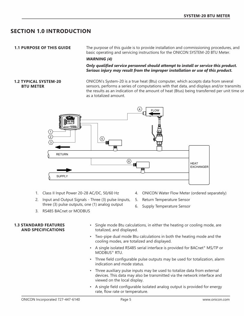
ONICON’s System-20 is a true heat (Btu) computer, which accepts data from several sensors, performs a series of computations with that data, and displays and/or transmits the results as an indication of the amount of heat (Btus) being transferred per unit time or as a totalized amount.
1.1 PURPOSE OF THIS GUIDE
1.2 TYPICAL SYSTEM-20 BTU METER
SUPPLY
RETURN
HEATEXCHANGER
BTU METERSYSTEM-20
Made in USA
BTU/HR49.50
1
3
FLOW4
5
6
2
1. Class II Input Power 20-28 AC/DC, 50/60 Hz2. Input and Output Signals - Three (3) pulse iinputs,
three (3) pulse outputs, one (1) analog output3. RS485 BACnet or MODBUS
4. ONICON Water Flow Meter (ordered separately)5. Return Temperature Sensor6. Supply Temperature Sensor
1.3 STANDARD FEATURES AND SPECIFICATIONS
• Single mode Btu calculations, in either the heating or cooling mode, are totalized, and displayed.
• Two-pipe dual mode Btu calculations in both the heating mode and the cooling modes, are totalized and displayed.
• A single isolated RS485 serial interface is provided for BACnet® MS/TP or MODBUS® RTU.
• Three field configurable pulse outputs may be used for totalization, alarm indication and mode status.
• Three auxiliary pulse inputs may be used to totalize data from external devices. This data may also be transmitted via the network interface and viewed on the local display.
• A single field configurable isolated analog output is provided for energy rate, flow rate or temperature.

ONICON Incorporated 727-447-6140 Page 6 www.onicon.com
SYSTEM-20 BTU METER
1.4 ADDITIONAL REQUIRED HARDWARE
The System-20 must be connected to a suitable volumetric flow meter and a matched pair of temperature sensors in order to calculate and report heat data. Please refer to ONICON’s flow meter literature, or contact ONICON for help in selecting the flow meter that will best fit your requirements.
Flow Meter Model Line Sizes Straight Run Required Notes
F-1100 Single Turbine Insertion Flow Meter 1 ¼" and larger 25 Can be used in 1" copper lines
F-1200 Dual Turbine Insertion Flow Meter 2 ½" and larger 15F-11XX Inline Turbine Flow Meter ¾" and 1" 25F-3500 Insertion Electromagnetic Flow Meter 1 ¼" and larger See manualFT-3100 and F-3200 Inline Electromagnetic Flow Meters ¼" and larger 5F-4300 Clamp-on Ultrasonic Flow Meter 2" and larger See manualF-4600 Inline Ultrasonic Flow Meter ½" - 2 ½" See manual
Temperature/Sensors
ONICON Standard Temperature Sensors (32°F – 200° F)
Pair of solid state temperature sensors with 0 – 20 mA outputs. Suitable for use with fluid temperatures up to 200° F.
Platinum RTD Temperature Sensors (32°F – 250° F)
Pair of 4-wire 1000 Ω Platinum RTD temperature sensors. Suitable for use with fluid temperatures up to 250° F.
Please refer to ONICON’s System-20 product literature, or contact ONICON for help in selecting the temperature sensors and thermowells that will best fit your requirements.
The System-20 was designed for installation and use in typical domestic and commercial environments that are free of corrosive liquids and fumes, direct liquid exposure, temperature extremes and vibrations.
The operating ambient air temperature range is -13°F to 140° F. The electrical power should be relatively clean, free of high frequency noise, large voltage transients, and protected from power surges and brown outs.
CAUTION (5)The System-20 battery cannot be retrofitted or replaced. Risk of fire explosion, and burns. DO NOT recharge, disassemble, crush, heat above 212°F (100°C) or incinerate. Please check your local ordinances for information concerning battery disposal.
IMPORTANT NOTE (6)The System-20 may be installed outdoors in protected spaces away from direct sunlight, rain, sleet or snow.
1.5 WORKING ENVIRONMENT

ONICON Incorporated 727-447-6140 Page 7 www.onicon.com
SYSTEM-20 BTU METER
1.6 SERIAL NUMBER The serial number of your System-20 is located on the top and inside the enclosure. The serial number is a unique identifier for the product. Please have this number available when contacting ONICON for assistance.
SECTION 2.0 UNPACKING
The System-20 is generally shipped in one package unless optional hardware or equipment is ordered. (Thermowells may have been shipped in advance.)
Please notify ONICON immediately if any of these items are missing.
Standard Documentation Includes: The System-20 BTU Meter Installation and Operation Guide The System-20 Certificate of Calibration
The System-20 Remove the System-20 from the shipping carton and inspect it for physical damage. Notify the freight carrier and ONICON immediately if any items are damaged in transit. Save all packaging. Btu meters ordered with a flow meter and temperature sensors will be delivered configured and programmed for use together as a system. The System-20 and the temperature sensor serial numbers will match. The flow meter serial number will be shown on the certificate of calibration and on the System-20 display.
Temperature Sensors If ordered, temperature sensors will generally be packed in the same carton with the System-20. Inspect the sensors and cables for damage. Each sensor will have a label attached with a serial number.
Flow Meter If ordered, the flow meter will be packaged in a separate carton. The flow meter ordered with this Btu meter came complete with an instruction manual. Please refer to it for detailed information regarding its installation, commissioning, and operation.
Flow Meter & Temperature Sensor Installation Hardware Installation hardware is ordered separately from the System-20, temperature sensors and flow meter. Note that this hardware is frequently shipped in advance of the meter(s).
2.1 CHECKING THAT YOU HAVE RECEIVED EVERYTHING

ONICON Incorporated 727-447-6140 Page 8 www.onicon.com
SYSTEM-20 BTU METER
SECTION 3.0 INSTALLATION
3.1 SITE SELECTION
The System-20 BTU Meter should be installed by personnel with related knowledge and experience in the heating, cooling, and fluid metering fields. ONICON is available to assist with technical recommendations and to provide guidance by telephone and/or e-mail during the installation and commissioning process. On-site field engineering, installation, and service are also available at an additional cost. The installer should use good trade practices and must adhere to all state and local building codes.
Before you begin, clean the external surfaces of all pipes at the installation sites so that they are free of debris, foreign matter, solids, leak inhibitors, and chemically aggressive substances. Flush the entire system so that it is free of flux, solder, pipe and tube cuttings and any other debris.
Careful attention to the site selection for the system components will help ensure an accurate energy measurement, help the installers with the initial installation, reduce start-up problems, and make future maintenance easier. For example, do not install the flow meter where it will be difficult for personnel to perform periodic maintenance. When selecting a site for mounting the components, refer to Section 1.5: WORKING ENVIRONMENT, as well as the following:
IMPORTANT NOTE (7)Proper site selection is critical to the performance of this Btu meter. Both the flow sensor and the temperature sensors must be properly located within the piping system in order to ensure an accurate energy measurement.
The System-20 Find an easily accessible location where field wiring connections can be made and meter readings can be taken from floor level. Mount the enclosure on a vibration free surface. Avoid locations such as the plenum of a fan coil, heat exchanger or any housing that may contain electric motors or other strong sources of electrical interference.
The Flow Meter When properly installed, the flow meter will only measure flow associated with that portion of the piping system for which the energy measurement is being made. The flow meter may be installed in either the supply or return line. Choose the location with the longest straight run of unobstructed pipe. Please refer to the flow meter installation manual for specific information regarding the straight run requirements for the flow meter.
The Temperature Sensors The two temperature sensors must be located so they accurately measure only the temperature of the supply line entering and the return line leaving the portion of the piping system for which the energy measurement is being made.
If possible, find an easily accessible location where field wiring connections can be made from floor level. This will facilitate future service. Place the temperature sensors away from strong sources of electrical noise that might affect the performance of the sensors.
One temperature sensor thermowell will need to be placed in the same pipe with the flow meter. It must be located at least five pipe diameters downstream of the flow meter leaving enough clearance to remove either sensor from the pipe without interference from the other sensor.

ONICON Incorporated 727-447-6140 Page 9 www.onicon.com
SYSTEM-20 BTU METER
IMPORTANT NOTE (8)The components of the ONICON System-20 BTU Measurement System must be configured, programmed and installed together as a system. Mixing components from different systems may result in significant measurement errors.
Find an easily accessible location where electrical connections can be made and meter readings can be taken from the floor level.
Mount the Btu meter on a vibration-free surface. Avoid sites such as the plenum of a fan coil, heat exchanger, or other housings containing motors.
The meter must be installed in protected spaces away from direct sunlight, rain, sleet or snow.
3.1 MECHANICAL INSTALLATION
7 5/8"
5 1/2"
5"
∅ 0.875" 5pl∅ 0.200" 4pl
SYSTEM-20BTU METER
7 5/8"
5 1/2"
5"
∅ 0.875" 5pl∅ 0.200" 4pl
SYSTEM-20BTU METER
7 5/8"
5 1/2"
5"
∅ 0.875" 5pl∅ 0.200" 4pl
SYSTEM-20BTU METER
CAUTION (9)DO NOT drill holes in the enclosure. Use only the openings that are provided.
IMPORTANT NOTE (10)Bonding between conduit connections is not automatic and shall be provided as part of the installation.

ONICON Incorporated 727-447-6140 Page 10 www.onicon.com
SYSTEM-20 BTU METER
3.2.1 Mounting the Enclosure
Use four screws for mounting the Btu meter. The mounting surface must be structurally sound and capable of withstanding a minimum weight of 40 lbs (18 kg).
Use the following screws for mounting.• Four Machine screws - #10-24 X 1.5” • Four Wood screws - No. 10 X 1.5” • Four Concrete screws - 3/16” X 1.5” with ¼" maximum hex, Phillips or slot
heads
Four mounting holes have been provided in the base of the enclosure shown below. Push out the rubber seals by inserting the mounting screws. Use the drilling template provided in Appendix 5 of this manual to drill the 4 holes required to mount the enclosure.
A DIN rail mounting hardware kit has been provided with this meter. Mount the DIN rail clips as shown.
CAUTION (11)DO NOT USE THE ENCLOSURE AS A TEMPLATE FOR DRILLING HOLES. Do not drill holes in the enclosure. Use only the openings that are provided.
ONICON Incorporated 727-447-6140 Page 11 www.onicon.com
SYSTEM-20 BTU METER
3.2.2 Thermowell Installation
IMPORTANT NOTE (12)It is important that no dirt or other foreign material be allowed into the thermowells as this could affect the thermal response of the system.
3.2.2.1 Standard Thermowells
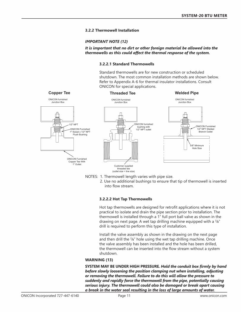
Standard thermowells are for new construction or scheduled shutdown. The most common installation methods are shown below. Refer to Appendix A-6 for thermal insulator installations. Consult ONICON for special applications.
ONICON furnishedJunction Box
ONICON furnishedbushing with
1/2" NPT outlet
Customer suppliedthreaded tee
(outlet size = line size)
1/2" NPT
ONICON Furnished1" Sweat x 1/2" NPT
Flush Bushing
ONICON furnishedJunction Box
ONICON FurnishedCopper Tee With
1" Outlet
ONICON Furnished1/2" NPT Welded
Branch Outlet
5/8" MinimumHole Size
ONICON furnishedJunction Box
Copper Tee Threaded Tee Welded Pipe
NOTES: 1. Thermowell length varies with pipe size.2. Use no additional bushings to ensure that tip of thermowell is inserted
into flow stream.
3.2.2.2 Hot Tap Thermowells
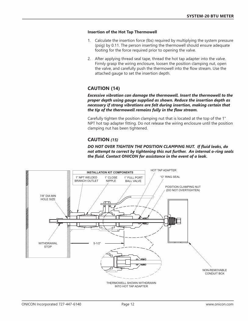
Hot tap thermowells are designed for retrofit applications where it is not practical to isolate and drain the pipe section prior to installation. The thermowell is installed through a 1” full port ball valve as shown in the drawing on next page. A wet tap drilling machine equipped with a 7/8” drill is required to perform this type of installation.
Install the valve assembly as shown in the drawing on the next page and then drill the 7/8” hole using the wet tap drilling machine. Once the valve assembly has been installed and the hole has been drilled, the thermowell can be inserted into the flow stream without a system shutdown.
WARNING (13)SYSTEM MAY BE UNDER HIGH PRESSURE. Hold the conduit box firmly by hand before slowly loosening the position clamping nut when installing, adjusting or removing the thermowell. Failure to do this will allow the pressure to suddenly and rapidly force the thermowell from the pipe, potentially causing serious injury. The thermowell could also be damaged or break apart causing a break in the water seal resulting in the loss of large amounts of water.
ONICON Incorporated 727-447-6140 Page 12 www.onicon.com
SYSTEM-20 BTU METER
Insertion of the Hot Tap Thermowell
1. Calculate the insertion force (lbs) required by multiplying the system pressure (psig) by 0.11. The person inserting the thermowell should ensure adequate footing for the force required prior to opening the valve.
2. After applying thread seal tape, thread the hot tap adapter into the valve. Firmly grasp the wiring enclosure, loosen the position clamping nut, open the valve, and carefully push the thermowell into the flow stream. Use the attached gauge to set the insertion depth.
CAUTION (14)Excessive vibration can damage the thermowell. Insert the thermowell to the proper depth using gauge supplied as shown. Reduce the insertion depth as necessary if strong vibrations are felt during insertion, making certain that the tip of the thermowell remains fully in the flow stream.
Carefully tighten the position clamping nut that is located at the top of the 1" NPT hot tap adapter fitting. Do not release the wiring enclosure until the position clamping nut has been tightened.
CAUTION (15)DO NOT OVER TIGHTEN THE POSITION CLAMPING NUT. If fluid leaks, do not attempt to correct by tightening this nut further. An internal o-ring seals the fluid. Contact ONICON for assistance in the event of a leak.
7/8” DIA MINHOLE SIZE
WITHDRAWAL STOP
1” NPT WELDED BRANCH OUTLET
1” CLOSE NIPPLE
1” FULL PORT BALL VALVE
HOT TAP ADAPTER
“O” RING SEAL
POSITION CLAMPING NUT (DO NOT OVERTIGHTEN)
5-1/2”
THERMOWELL SHOWN WITHDRAWN INTO HOT TAP ADAPTER
NON-REMOVABLE CONDUIT BOX
INSTALLATION KIT COMPONENTS
ONICON Incorporated 727-447-6140 Page 13 www.onicon.com
SYSTEM-20 BTU METER
Removal of the Hot Tap ThermowellWARNING (16)Maintain a firm hold on the wiring enclosure until the thermowell is completely withdrawn and the valve is closed.
1. System pressure will try to push the thermowell out of the flow stream when the clamping nut is released. Be sure to establish safe footing prior to loosening the clamping nut. The force pushing out against the thermowell is the same as the insertion force.
2. Grasp the wiring enclosure firmly, holding the thermowell in the pipe and then loosen the position clamping nut. Slowly withdraw the thermowell from the pipe.
3. After the thermowell is completely withdrawn, carefully close the isolation valve.
IMPORTANT NOTE (17)Rotating the thermowell as you slowly withdraw it through the valve will ensure that the lower tip is fully withdrawn and completely free of the valve. If resistance is felt when closing the valve, open valve fully and rotate the well as you pull it further out of the pipe.
3.2.3 Temperature Sensor Installation
When ordered with the System-20, temperature sensors are factory matched and tagged by serial number to a specific Btu meter. ONICON standard temperature sensors are also designated and labeled as the SUPPLY or RETURN sensor and must be installed per these labels.
3.2.3.1 ONICON Standard Temperature Sensor Installation
ONICON standard temperature sensors must be used as a pair to maintain differential accuracy. They are also designated and labeled as the SUPPLY or RETURN sensor and must be installed accordingly. To install, apply a thin coat of thermal compound to the sensor tip area and insert it all the way into the thermowell until it contacts the bottom of the cavity. Gently tighten the retainer nut. DO NOT OVERTIGHTEN. The thermowell completely seals the plumbing system without the retainer nut. The only purpose for the nut is to ensure that the sensor tip will remain in contact with the bottom of the thermowell.

ONICON Incorporated 727-447-6140 Page 14 www.onicon.com
SYSTEM-20 BTU METER
TEMPERATURE SENSOR
PLASTIC END PIECE
SPACER SLEEVE(Length varies with thermowell length)
ELECTRONICS MODULE
SUPPLY
S/N 123456
SIGNAL (RED)
REFERENCE (BLACK)
TEMPERATURE SENSOR
TEMPERATURE SENSOR INSTALLED IN THERMOWELL
SIGN
AL (RED
)
REFER
ENC
E (BLACK)
SUPPLY
S/N 123456
PROVIDE 18-22 GA TWISTEDSHIELDED PAIR.COIL ONE FOOT OF EXTRACABLE IN CONDUIT BOX.1/2” NPT WELDED
BRANCH OUTLET
PLACE ELECTRONICS MODULE IN BOX AFTER
CONNECTING WIRES
5/8” MINIMUM HOLE SIZE
1/2” HOLE FOR CONDUIT OR
STRAIN RELIEF FITTING
CAUTION (18)DO NOT OVERTIGHTEN. The thermowell completely seals the plumbing system. Screwing in the sensor just ensures that the sensor tip will remain in contact with the bottom of the thermowell.

ONICON Incorporated 727-447-6140 Page 15 www.onicon.com
SYSTEM-20 BTU METER
The System-20 is provided with three ¾" conduit openings along the bottom of the enclosure for power and signal cables. Two openings are provided with knockout seals. The power cable should enter the enclosure through the right hand opening. Do not remove the seals from unused openings. To access the wiring connections, remove the two cover screws shown below.
3.3 ELECTRICAL INSTALLATION
AC/DC POWER IN1 2 3 4 5 6
AUX POWER OUT
(A)
(A)
(B)
(B)
(A)
(A)
(B)
(B)
2 4WIRE
1TB5 TEMPERATURE
2 3 4 5
RS485+
RS485-
RS485COM
SHIELD
IN 1 (+)
IN 1 (-)
IN 2 (+)
IN 2 (-)
IN 3 (+)
IN 3 (-)
OUT 1 (+)
OUT 1 (-)
4-20mA OUT (+)
4-20mA COM (-)
0-10V OUT (+)
0-10V COM (-)
1
TB1 RS-4852 3 4 1 2 3 4 5 1 2 3 4 5 1 2 3 4
1 2 3 4 1 2 3 4 1 2 3 1 2 3 4 5TB6 RTD SUP TB7 RTD RET TB8 TURB TB9 FLOWMETER
TB2 PULSE IN6 6
TB 3 PULSE OUT TB4 ANA OUT
SUPTEMP (+)
SUPTEMP (-)
SHIELD
RETTEMP (+)
RETTEMP (-)
24VTURBOUT 2 (+)
OUT 2 (-)
OUT 3 (+)
OUT 3 (-)
TURB FREQ
TURBCOM
24 VDC (+)
4-20mA IN
FREQ IN
SIG COMM
24 VDC (-)EARTH
24V N (-)
24V L (+)
EARTH
24V N (-)
24V L (+)
24V ONLY
!
JMP1 RS485 LOAD
TERMINATED UNTERMINATED
TB102 4WIRE
2 4WIRE
2 4WIRE
JP3J2
COVER SCREWS
WARNING (19)Disconnect main power before proceeding.

ONICON Incorporated 727-447-6140 Page 16 www.onicon.com
SYSTEM-20 BTU METER
3.3.1 Power and Signal Wiring Connections
AC/DC POWER IN1 2 3 4 5 6
AUX POWER OUT
(A)
(A)
(B)
(B)
(A)
(A)
(B)
(B)
2 4WIRE
1TB5 TEMPERATURE
2 3 4 5
RS485+
RS485-
RS485COM
SHIELD
IN 1 (+)
IN 1 (-)
IN 2 (+)
IN 2 (-)
IN 3 (+)
IN 3 (-)
OUT 1 (+)
OUT 1 (-)
4-20mA OUT (+)
4-20mA COM (-)
0-10V OUT (+)
0-10V COM (-)
1
TB1 RS-4852 3 4 1 2 3 4 5 1 2 3 4 5 1 2 3 4
1 2 3 4 1 2 3 4 1 2 3 1 2 3 4 5TB6 RTD SUP TB7 RTD RET TB8 TURB TB9 FLOWMETER
TB2 PULSE IN6 6
TB3 PULSE OUT TB4 ANA OUT
SUPTEMP (+)
SUPTEMP (-)
SHIELD
RETTEMP (+)
RETTEMP (-)
24VTURBOUT 2 (+)
OUT 2 (-)
OUT 3 (+)
OUT 3 (-)
TURB FREQ
TURBCOM
24 VDC (+)
4-20mA IN
FREQ IN
SIG COMM
24 VDC (-)EARTH
24V N (-)
24V L (+)
EARTH
24V N (-)
24V L (+)
24V ONLY!
JMP1 RS485 LOAD
TERMINATED UNTERMINATED
TB10
2 4WIRE
2 4WIRE
2 4WIRE
JP3J2
1 2 3
TB8 TURB
3. (-) SUPPLY COMMON (BLACK)2. (+) FREQUENCY (GREEN)1. (+) 24 VDC SUPPLY (RED)
1 2 3
TB9FLOWMETER
5. (-) 24 VDC (BLACK)4. SIGNAL COMMON3. FREQUENCY IN
4 5
1 2 3
TB10POWER INPUT
6. EARTH GROUND5. (-) N4. (+) L
4 5
2. 4-20 mA IN1. (+) 24 VDC (RED)
6
3. EARTH GROUND2.1. (+) L
(-) N
SYS-20 AC/DCPOWER IN
1
2
3
4
5
1. This terminal block is ONLY for use with ONICON F-1000 Series Turbine Flow Meters.
2. Voltage output for use with non-ONICON Flow Meters - 24VDC @ 50 mA maximum.
3. See meters installation & operation guide for additional information on properly wiring & grounding the meter.
4. Class II power supply requirements: 20 - 28 V AC/DC, 50 / 60 Hz 500 mA DC or 1A AC total input current.
5. 24 VAC aux power output connection for all flow meters except the F-1000 Series.

ONICON Incorporated 727-447-6140 Page 17 www.onicon.com
SYSTEM-20 BTU METER
WARNING (20)The System-20 must be connected to earth ground for proper operation. Failure to do so may result in erratic operation.
CAUTION (21)Minimum temperature rating of the cable to be connected to the field wiring terminals, 140°F (60°C).
IMPORTANT NOTE (22)The System-20 shall be used with an external Class II power supply.
FLOW METERS OUTPUT SIGNAL CONNECTIONS
Flow Meters with Frequency
Output
Models System-20 Terminal # Signal Input to System-20 System-20
Terminal #Power Output to Flow
Meters
F-1000 Series TB8-2 (+) Frequency Input (Green) TB8-1TB8-3
(+) 24 VDC Supply (Red)(-) Supply Common (Black)
F-3500 SeriesFSM-3 SeriesFT-3100 SeriesF-3200 SeriesNon-ONICON Meters
TB9-3TB9-4TB2-5TB2-6
(+) Frequency Input (Green) TB10-4 (+) 24 VAC/DC(-) Signal Common (Yellow) TB10-5 (-) 24 VAC/DC(+) Direction (bi-directional) (Orange/ Black) TB10-6 Earth Ground
(-) Direction (bi-directional) (White/ Black)
Note: Wiring colors are ONLY applicable for F-3500 Series
Flow Meters with Active
Analog Output
Models System-20 Terminal # Signal Input to System-20 System-20
Terminal #Power Output to Flow
Meters
F-4300 SeriesF-4600 Series* F-1500 Series * F-2000 Series Non-ONICON Meters
TB9-2TB9-4TB2-5TB2-6
(+) 4-20 mA (Blue) TB10-4 (+) 24 VAC/DC(-) Signal Common (Brown) TB10-5 (-) 24 VAC/DC(+) Direction (bi-directional switch/ contacts) TB10-6 Earth Ground
(-) Direction (bi-directional switch/ contacts)
Note: Wiring colors are ONLY applicable for F-4600 Series* Requires external input powers
Flow Meters with Loop
Power/ Passive Analog Output
Models System-20 Terminal # Signal Input to System-20
* F-1500 Series * F-2000 Series
TB9-1TB9-1
(+) 24 VDC(+) 4-20 mA
* Requires external input powers. Refer to flow meter model number to confirm output signal type.

ONICON Incorporated 727-447-6140 Page 18 www.onicon.com
SYSTEM-20 BTU METER
3.3.2 Pulse Input and Output Wiring Connections
AC/DC POWER IN1 2 3 4 5 6
AUX POWER OUT
(A)
(A)
(B)
(B)
(A)
(A)
(B)
(B)
2 4WIRE
1TB5 TEMPERATURE
2 3 4 5
RS485+
RS485-
RS485COM
SHIELD
IN 1 (+)
IN 1 (-)
IN 2 (+)
IN 2 (-)
IN 3 (+)
IN 3 (-)
OUT 1 (+)
OUT 1 (-)
4-20mA OUT (+)
4-20mA COM (-)
0-10V OUT (+)
0-10V COM (-)
1
TB1 RS-4852 3 4 1 2 3 4 5 1 2 3 4 5 1 2 3 4
1 2 3 4 1 2 3 4 1 2 3 1 2 3 4 5TB6 RTD SUP TB7 RTD RET TB8 TURB TB9 FLOWMETER
TB2 PULSE IN6 6
TB3 PULSE OUT TB4 ANA OUT
SUPTEMP (+)
SUPTEMP (-)
SHIELD
RETTEMP (+)
RETTEMP (-)
24VTURBOUT 2 (+)
OUT 2 (-)
OUT 3 (+)
OUT 3 (-)
TURB FREQ
TURBCOM
24 VDC (+)
4-20mA IN
FREQ IN
SIG COMM
24 VDC (-)EARTH
24V N (-)
24V L (+)
EARTH
24V N (-)
24V L (+)
24V ONLY!
JMP1 RS485 LOAD
TERMINATED UNTERMINATED
TB10
2 4WIRE
2 4WIRE
2 4WIRE
JP3J2
1 2 3
TB3PULSE OUTPUT
6 - (-) PULSE OUT 35 - (+) PULSE OUT 34 - (-) PULSE OUT 2
4 5 6
3 - (+) PULSE OUT 22 - (-) PULSE OUT 11 - (+) PULSE OUT 1
1 2 3
TB2PULSE INPUT
6 - (-) PULSE IN 35 - (+) PULSE IN 34 - (-) PULSE IN 2
4 5 6
3 - (+) PULSE IN 22 - (-) PULSE IN 11 - (+) PULSE IN 1
1
2
AC/DC POWER IN1 2 3 4 5 6
AUX POWER OUT
(A)
(A)
(B)
(B)
(A)
(A)
(B)
(B)
2 4WIRE
1TB5 TEMPERATURE
2 3 4 5
RS485+
RS485-
RS485COM
SHIELD
IN 1 (+)
IN 1 (-)
IN 2 (+)
IN 2 (-)
IN 3 (+)
IN 3 (-)
OUT 1 (+)
OUT 1 (-)
4-20mA OUT (+)
4-20mA COM (-)
0-10V OUT (+)
0-10V COM (-)
1
TB1 RS-4852 3 4 1 2 3 4 5 1 2 3 4 5 1 2 3 4
1 2 3 4 1 2 3 4 1 2 3 1 2 3 4 5TB6 RTD SUP TB7 RTD RET TB8 TURB TB9 FLOWMETER
TB2 PULSE IN6 6
TB3 PULSE OUT TB4 ANA OUT
SUPTEMP (+)
SUPTEMP (-)
SHIELD
RETTEMP (+)
RETTEMP (-)
24VTURBOUT 2 (+)
OUT 2 (-)
OUT 3 (+)
OUT 3 (-)
TURB FREQ
TURBCOM
24 VDC (+)
4-20mA IN
FREQ IN
SIG COMM
24 VDC (-)EARTH
24V N (-)
24V L (+)
EARTH
24V N (-)
24V L (+)
24V ONLY!
JMP1 RS485 LOAD
TERMINATED UNTERMINATED
TB10
2 4WIRE
2 4WIRE
2 4WIRE
JP3J2
1 2 3
TB4ANALOG OUTPUT
4. (-) 0-10 V COMMON
4
3. (+) 0-10 V OUT2. (-) 4-20 mA COMMON1. (+) 4-20 mA OUT
1 2 3
TB1RS485 OUTPUT
4. SHIELD
4
3. RS485 COMMON2. (-) RS4851. (+) RS485
1 - 2 = 120 Ω
JMP1RS485 TERMINATION
2 - 3 = NON TERMINATED
1
1. Maximum 30 V, 50 mA Pulse duration: 50, 100, 500 or 1000 ms2. For use with devices providing sinking open collector or dry contact outputs.
3.3.3 Analog Output and Serial Communication Wiring Connections
1. Terminals TB4-3 & TB4-4 configured as 0-5V or 0-10V output

ONICON Incorporated 727-447-6140 Page 19 www.onicon.com
SYSTEM-20 BTU METER
3.3.4 Temperature Sensor Wiring Connections
AC/DC POWER IN1 2 3 4 5 6
AUX POWER OUT
(A)
(A)
(B)
(B)
(A)
(A)
(B)
(B)
2 4WIRE
1TB5 TEMPERATURE
2 3 4 5
RS485+
RS485-
RS485COM
SHIELD
IN 1 (+)
IN 1 (-)
IN 2 (+)
IN 2 (-)
IN 3 (+)
IN 3 (-)
OUT 1 (+)
OUT 1 (-)
4-20mA OUT (+)
4-20mA COM (-)
0-10V OUT (+)
0-10V COM (-)
1
TB1 RS-4852 3 4 1 2 3 4 5 1 2 3 4 5 1 2 3 4
1 2 3 4 1 2 3 4 1 2 3 1 2 3 4 5TB6 RTD SUP TB7 RTD RET TB8 TURB TB9 FLOWMETER
TB2 PULSE IN6 6
TB3 PULSE OUT TB4 ANA OUT
SUPTEMP (+)
SUPTEMP (-)
SHIELD
RETTEMP (+)
RETTEMP (-)
24VTURBOUT 2 (+)
OUT 2 (-)
OUT 3 (+)
OUT 3 (-)
TURB FREQ
TURBCOM
24 VDC (+)
4-20mA IN
FREQ IN
SIG COMM
24 VDC (-)EARTH
24V N (-)
24V L (+)
EARTH
24V N (-)
24V L (+)
24V ONLY!
JMP1 RS485 LOAD
TERMINATED UNTERMINATED
TB10
2 4WIRE
2 4WIRE
2 4WIRE
JP3J2
1 2 3
TB7RTDs RETURN
4
1 2 3
TB5ONICON FIXED RANGE OR
SCALED INPUT ANALOGTEMPERATURE SENSORS
4. (+) RETURN TEMP
4
3. SHIELD2. (-) SUPPLY TEMP1. (+) SUPPLY TEMP
5
5. (-) RETURN TEMP
RTD SELECTIONJUMPERS
1 2 3
TB6RTDs SUPPLY
4
4. (B) COMPENSATION LEAD (not used w/ 2 wire RTD)3. (B) RTD SIGNAL LEAD2. (A) COMPENSATION LEAD (not used w/ 2 wire RTD)1. (A) RTD SIGNAL LEAD
1 - 2 = 2-WIRE RTD2 - 3 = 4-WIRE RTD
1
2
2
3
4. (B) COMPENSATION LEAD (not used w/ 2 wire RTD)3. (B) RTD SIGNAL LEAD2. (A) COMPENSATION LEAD (not used w/ 2 wire RTD)1. (A) RTD SIGNAL LEAD
1. This terminal block for use with an ONICON fixed range (O1 & O2) or loop powered 4-20mA scalable range temperature sensors. See Temperature Inputs Wiring Diagram on page 20 for additional information.
2. These terminal blocks for use with an 1000 ohms platinum RTD temperature sensors (R2 & R3). See Temperature Inputs Wiring Diagram on page 20 for additional information.
3. Select jumper position 1 & 2 for 2-wire RTD or 2 & 3 for 4-wire RTD.

ONICON Incorporated 727-447-6140 Page 20 www.onicon.com
SYSTEM-20 BTU METER
3.3.5 Temperature Input Wiring Details
1 2 3 4
ONICON FIXED RANGE or LOOP POWERED 4-20mA SCALABLE RANGETEMPERATURE INPUTS
TERMINAL BLOCK TB5
1 2 3
4. (+) RETURN TEMP
4
3. SHIELD2. (-) SUPPLY TEMP1. (+) SUPPLY TEMP
5
5. (-) RETURN TEMP(+) Signal (-) Reference Return Temperature Sensor
Shield
(+) Signal(-) Reference Supply Temperature Sensor
1000 OHMS 4-WIRE PLATINUM RTD TEMPERATURE INPUTSw/ ATTACHED PIGTAILS CABLE
TERMINAL BLOCK TB6 (SUP)& TB7 (RET)
4. (B) COMPENSATION LEAD3. (B) RTD SIGNAL LEAD2. (A) COMPENSATION LEAD1. (A) RTD SIGNAL LEAD Brown*
Yellow*White*Green*
1000 OHMS 4-WIRE PLATINUM TEMPERATURE INPUTSw/ INTEGRAL CONDUIT READY JUNCTION BOX
1 2 3 4
TERMINAL BLOCK TB6 (SUP)& TB7 (RET)
* Cable color coding to DIN 47100
4. (B) COMPENSATION LEAD3. (B) RTD SIGNAL LEAD2. (A) COMPENSATION LEAD1. (A) RTD SIGNAL LEAD
Refer to Temperature Sensor Connection on page 19 for additional details on the terminal location.

ONICON Incorporated 727-447-6140 Page 21 www.onicon.com
SYSTEM-20 BTU METER
SECTION 4.0 START-UP AND COMMISSIONING
4.1 START-UP When power is first applied to the meter the display will be illuminated and the following start screen will appear. Momentarily press SEL (select) to access the operating mode (User Screens) display pages.
Verify that the meter is functional by stepping through the display pages and confirming the flow rate and temperature data is within expected norms. Momentarily press NEXT or BACK to change the displayed page. A complete list of the display pages is provided on the following pages.
When reviewing the displayed data, note the factory programmed engineering units on each display page (e.g. kBtu, gallons, kBtu/h, gpm, °F, etc.). Note any changes that may be necessary. These will need to be made during commissioning.
When reviewing the Supply and Return temperature display pages, note which one has the word “FLOW” in the lower left corner of the page. This is an indication of the flow sensor location in the piping system. Verify the actual location of the flow sensor in the piping system. It is critical that the correct location (supply or return) be programmed into the meter.
CAUTION (23)During start-up and commissioning, the FLOW location must be properly identified as being in the supply or return pipe of the heat exchange circuit. The sensor’s position must then be programmed into the meter. Failure to do so will result in significant errors in both the flow and energy measurements.
To return to the commissioning mode from the user screens, momentarily press MENU. The following page will appear. Momentarily press EXIT to return to the start screen.
User Screens
NEXT
SEL
!Commissioning
NEXT
MENU
0kBtu
!Energy TotalBACK
NEXT
SEL
More Totals
Meter Data
! AlarmDiagnostic
EXITBACK

ONICON Incorporated 727-447-6140 Page 22 www.onicon.com
SYSTEM-20 BTU METER
4.1.1 Single and Dual Mode Display Pages
NEXT
MENU
0kBtu
!Energy TotalBACK
NEXT
MENU
0gallons x 1
!Volume TotalBACK
NEXT
MENU
0kBtu/h x 1
!Energy RateBACK
NEXT
MENU
0gpm x 1
!Volume RateBACK
NEXT
MENU0.0
Deg F
!SupplyTemperature
BACK
NEXT
MENU
0.0Deg F
!ReturnTemperature
BACK
NEXT
MENU
0.0Deg F
!Delta TemperatureBACK
NEXT
MENU
0Counts
!Auxiliary Input 1BACK
NEXT
MENU
0Counts
!Auxiliary Input 2BACK
NEXT
MENU
0Counts
!Auxiliary Input 3BACK
NEXT
MENU
0hours
!Run hoursBACK
Mode 1
NEXT
MENU
0kBtu
!Energy TotalBACK
Mode 2
Mode 1
NEXT
MENU
0gallons x 1
!Volume TotalBACK
Mode 2
NEXT
MENU
Mode 2!Mode StatusBACK
NEXT
MENU
0gallons x 1
!Volume TotalBACK
NEXT
MENU
0kBtu/h x 1
!Energy RateBACK
NEXT
MENU
0gpm x 1
!Volume RateBACK
NEXT
MENU0.0
Deg F
!SupplyTemperature
BACK
NEXT
MENU0.0
Deg F
!ReturnTemperature
BACK
NEXT
MENU
0.0Deg F
!Delta TemperatureBACK
NEXT
MENU
0Counts
!Auxiliary Input 1BACK
NEXT
MENU
0Counts
!Auxiliary Input 2BACK
NEXT
MENU
0Counts
!Auxiliary Input 3BACK
NEXT
MENU
0hours
!Run hoursBACK
NEXT
MENU
0kBtu
!Energy TotalBACK
* Auxiliary input pages only appear when enabled.

ONICON Incorporated 727-447-6140 Page 23 www.onicon.com
SYSTEM-20 BTU METER
4.1.2 Additional Display Pages
NEXT
MENU
0kBtu
YTD Energy
NEXT
MENU
0gallons
YTD Volume
NEXT
MENU
0kBtu
Prev. Yr Energy
NEXT
MENU
0gallons
Prev. Yr Volume
NEXT
MENU
0kBtu
User Energy Total
NEXT
MENU
0kBtu
Mode 1
NEXT
MENU
0kBtu
YTD Energy
Mode 2
Mode 1
NEXT
MENU
0gallons
YTD Volume
Mode 2
NEXT
MENU
0gallons
YTD Volume
NEXT
MENU
0kBtu
Prev. Yr Energy
NEXT
MENU
0gallons
Prev. Yr Volume
NEXT
MENU
0KBtu
User Energy Total
NEXT
MENU
0kBtu
YTD EnergyBACK
EXIT
BACK
EXIT
BACK
EXIT
BACK
EXIT
BACK
EXIT
BACK
EXIT
BACK
EXIT
BACK
EXIT
BACK
EXIT
BACK
EXIT
BACK
EXIT
BACK
EXIT
BACK
EXIT
NEXT
MENU
0gallons
Prev. Yr Volume
NEXT
MENU
0kBtu
Prev. Yr Energy
Mode 1
BACK
EXIT
BACK
EXIT
Mode 2
Mode 1
Mode 2
User Energy Total
Mode 1
Mode 2
NEXT
MENU
Low Flow
Alarm
NEXT
MENU
0Reset Count
NEXT
MENU
0Max 200
Flow CountBACK
EXIT
BACK
EXIT
BACK
EXIT
Diagnostics
NEXT
MENU
Flow MeterSerial Number
NEXT
MENUNEXT
MENU
HH:MM:SSCurrent Time
NEXT
MENU
App:Boot:
Versions
NEXT
MENU
0Serial Number
BACK
EXIT
BACK
EXIT
BACK
EXIT
BACK
EXIT
BACK
EXIT
Meter Data
NEXT
MENU
YYYY/MM/DD
Manuafacture Date
NEXT
MENU
Current DateBACK
EXIT
BACK
EXIT
YYYY/MM/DD
AlarmsAlarm MesagesFlow Temp OpenLow FlowLow Supply TempLow Return Tempdt< Minimum
Temperature SensorSerial Number
ONICON Incorporated 727-447-6140 Page 24 www.onicon.com
SYSTEM-20 BTU METER
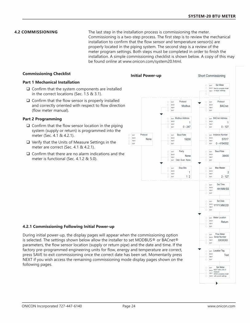
The last step in the installation process is commissioning the meter. Commissioning is a two-step process. The first step is to review the mechanical installation to confirm that the flow sensor and temperature sensor(s) are properly located in the piping system. The second step is a review of the meter program settings. Both steps must be completed in order to finish the installation. A simple commissioning checklist is shown below. A copy of this may be found online at www.onicon.com/system20.html.
4.2 COMMISSIONING
Commissioning Checklist
Part 1 Mechanical Installation Confirm that the system components are installed in the correct locations (Sec. 1.5 & 3.1).
Confirm that the flow sensor is properly installed and correctly oriented with respect to flow direction (flow meter manual).
Part 2 Programming Confirm that the flow sensor location in the piping system (supply or return) is programmed into the meter (Sec. 4.1 & 4.2.1).
Verify that the Units of Measure Settings in the meter are correct (Sec. 4.1 & 4.2.1).
Confirm that there are no alarm indications and the meter is functional (Sec. 4.1.2 & 5.0).
NEXT
Meter Factor
XX.XXX
EXIT
BACK
NEXT
BACK
EDIT
EXIT Full ScaleMaximum Flow
XXXXNEXT
BACK
EDIT
EDIT
0 - 9999999
EXIT Flow Damping
11 - 32
NEXT
BACK
EDIT
Pulses per units
% of maximum flow
EXIT Flow Input Source
FrequencyNEXT
BACK
EDIT
EXIT Flow Input Source
4-20MaNEXT
BACK
EDIT
EXIT Energy Units
kBtu x 1Select Units
NEXT
BACK
EDIT
EXIT Energy Multiplier
EXIT Energy Rate
kBtu/h x 1Select Units
NEXT
BACK
EDIT
NEXT
BACK
EDIT
NEXT
Energy Rate Multiplier
kBtu/h x 1EXIT
BACK
EXIT Energy Damping
1NEXT
BACK
EDIT
EDIT
1 - 32
kBtu x 1
X.X
Supply Temperature 20mA
Return Temperature 4mA
Return Temperature 20mA
EXIT Temperature Sensor Type
1k Ohm RTDNEXT
BACK
EDIT
Auxiliary InputLabel 1
Configure Auxiliary Input 2
Auxiliary InputLabel 2
Configure Auxiliary Input 3
Auxiliary InputLabel 3
Units of Measure Settings Continued
NEXT
ModeSingle
EXIT
BACK
NEXT
BACK
EDIT
Single/Dual/BiDirectionalEDIT
EXIT Flow Multiplier
NEXT
Volume Multiplier
gal x 1
EXIT
BACK
NEXT
BACK
EDIT
EXIT Flow Units
gpm x 1NEXT
BACK
EDIT
EDIT
Select Units
gpm x 1
NEXT
Medium
WaterEXIT
BACK
EDIT
EXIT Flow Rate Units
gpm x 1Select Units
NEXT
BACK
EDIT
NEXT
Flow 20mA
XXXX
EXIT
BACK
EXIT Low Flow Cutoff
X.XNEXT
BACK
EDIT
EDIT
% of maximum flow
EXIT Flow Damping
11 - 32
NEXT
BACK
EDIT
0 - 9999999
EXIT Meter Volume Units
gallonsSelect Units
NEXT
BACK
EDIT
EXIT Low Flow Cutoff
NEXTX
EXIT
BACK
EXIT
XXXNEXT
BACK
EDIT
EDIT
EXIT Supply Temperature 4mA
XNEXT
BACK
EDIT
EXIT Temperature Sensor Type
ScalableNEXT
BACK
EDIT
EXIT Volume Units
gallonsSelect Units
BACK
EDIT
ModbusNEXT
BACK
EDIT
EXIT Protocol
NEXT
BACK
EDIT
NEXT
BACK
EDIT
EXIT Max Master
2NEXT
BACK
EDIT 2 - 127
Baud Rate
19200NEXT
BACK
EDIT
Odd Even NoneNEXT
BACK
EDIT
NEXT
BACK
EDIT
EXIT Set Time
HH:MM:SSNEXT
BACK
EDIT
1 2
NEXT
BACK
EDIT
EXIT Set MeterNEXT edits units ofmeasureSAVE completes installwith current settings
EXIT Meter Location
ReturnNEXT
BACK
EDIT
EXIT Set Date
YYYY:MM:DD
NEXT
Set MeterNext to complete Installor adjust settings.
EXIT
BACK
NEXT
BACK
EDIT
EXIT Protocol
BACnetNEXT
BACK
EDIT
EXIT Modbus Address
EXIT
EXIT Parity
10 - 247
None
EXIT Stop Bits
1
NEXT
EXIT Flow MeterSerial Number
XXXXXXNEXT
BACK
EDIT
EXIT Location Tag
TextNEXT
BACK
EDIT
NEXT
BACK
NoneNEXT
BACK
EDIT
EXIT Protocol
SAVE
EXIT
XXXNEXT
BACK
EDIT
Pulse Output 3
Alarm
Select Type
Select Multiplier
EXIT
NEXT
BACK
EDIT
EXIT
NEXT
Analog Volts Signal
0 - 10VEXIT
BACK
NEXT
BACK
EDIT
EXIT Analog Output Max
2000NEXT
BACK
EDIT
NEXT
BACK
EDIT
EDIT
Analog Output
Energy Rate
Analog Output Min
0
Set MeterPress NEXT edit unitsof measureSAVE completes installwith current settings
Select Type
Select Signal
Energy Rate - kBtu/h
Energy Rate - kBtu/h
EXIT BACnet Address
EXIT Instance Number
EXIT Baud Rate
10 - 127
570170 - 4194302
38400
Short Commissioning
NEXT
BACK
EDIT
NEXT
BACK
EDIT
Pulse
EXIT
EXIT
NEXT
BACK
EDIT
NEXT
BACK
EDIT
EXIT
NEXT
EXIT
BACK
NEXT
BACK
EDIT
EXIT Pulse Duration
500 msNEXT
BACK
EDIT
EDIT
Counts
Pulse Output 1
Energy Total
Volume Pulse Scaling
x 1
Select Type
Pulse Output 2
Volume Total
Select Type
EXIT
EXIT
NEXT
BACK
EDIT
NEXT
BACK
EDIT
EXIT
EXIT
NEXT
Configure Auxiliary Input 1
PulseEXIT
BACK
NEXT
BACK
EDIT
EXIT
CountsNEXT
BACK
EDIT
NEXT
BACK
EDIT
EDIT
Supply Temperature Slope
10.000
Return Temperature Offset
+0.000
Return Temperature Slope
10.000
Pulse
Counts
EXIT
EXIT
EXIT Temperature
EXIT Temperature SensorSerial Number
XXXXXX
NEXT
BACK
EDIT
NEXT
BACK
EDIT
Deg FSelect Units
EXIT Supply Temperature Offset
EXIT
NEXT
BACK
EDIT
EXIT Temperature SensorType
ONICONNEXT
BACK
EDIT
NEXT
BACK
EDIT
+0.000
Units of Measure SettingsInitial Power-up
4.2.1 Commissioning Following Initial Power-up
During initial power-up, the display pages will appear when the commissioning option is selected. The settings shown below allow the installer to set MODBUS® or BACnet® parameters, the flow sensor location (supply or return pipe) and the date and time. If the factory pre-programmed engineering units for flow, energy and temperature are correct, press SAVE to exit commissioning once the correct date has been set. Momentarily press NEXT if you wish access the remaining commissioning mode display pages shown on the following pages.

ONICON Incorporated 727-447-6140 Page 25 www.onicon.com
SYSTEM-20 BTU METER
NEXT
Meter Factor
XX.XXX
EXIT
BACK
NEXT
BACK
EDIT
EXIT Full ScaleMaximum Flow
XXXXNEXT
BACK
EDIT
EDIT
0 - 9999999
EXIT Flow Damping
11 - 32
NEXT
BACK
EDIT
Pulses per units
% of maximum flow
EXIT Flow Input Source
FrequencyNEXT
BACK
EDIT
EXIT Flow Input Source
4-20MaNEXT
BACK
EDIT
EXIT Energy Units
kBtu x 1Select Units
NEXT
BACK
EDIT
EXIT Energy Multiplier
EXIT Energy Rate
kBtu/h x 1Select Units
NEXT
BACK
EDIT
NEXT
BACK
EDIT
NEXT
Energy Rate Multiplier
kBtu/h x 1EXIT
BACK
EXIT Energy Damping
1NEXT
BACK
EDIT
EDIT
1 - 32
kBtu x 1
X.X
Supply Temperature 20mA
Return Temperature 4mA
Return Temperature 20mA
EXIT Temperature Sensor Type
1k Ohm RTDNEXT
BACK
EDIT
Auxiliary InputLabel 1
Configure Auxiliary Input 2
Auxiliary InputLabel 2
Configure Auxiliary Input 3
Auxiliary InputLabel 3
Units of Measure Settings Continued
NEXT
ModeSingle
EXIT
BACK
NEXT
BACK
EDIT
Single/Dual/BiDirectionalEDIT
EXIT Flow Multiplier
NEXT
Volume Multiplier
gal x 1
EXIT
BACK
NEXT
BACK
EDIT
EXIT Flow Units
gpm x 1NEXT
BACK
EDIT
EDIT
Select Units
gpm x 1
NEXT
Medium
WaterEXIT
BACK
EDIT
EXIT Flow Rate Units
gpm x 1Select Units
NEXT
BACK
EDIT
NEXT
Flow 20mA
XXXX
EXIT
BACK
EXIT Low Flow Cutoff
X.XNEXT
BACK
EDIT
EDIT
% of maximum flow
EXIT Flow Damping
11 - 32
NEXT
BACK
EDIT
0 - 9999999
EXIT Meter Volume Units
gallonsSelect Units
NEXT
BACK
EDIT
EXIT Low Flow Cutoff
NEXTX
EXIT
BACK
EXIT
XXXNEXT
BACK
EDIT
EDIT
EXIT Supply Temperature 4mA
XNEXT
BACK
EDIT
EXIT Temperature Sensor Type
ScalableNEXT
BACK
EDIT
EXIT Volume Units
gallonsSelect Units
BACK
EDIT
ModbusNEXT
BACK
EDIT
EXIT Protocol
NEXT
BACK
EDIT
NEXT
BACK
EDIT
EXIT Max Master
2NEXT
BACK
EDIT 2 - 127
Baud Rate
19200NEXT
BACK
EDIT
Odd Even NoneNEXT
BACK
EDIT
NEXT
BACK
EDIT
EXIT Set Time
HH:MM:SSNEXT
BACK
EDIT
1 2
NEXT
BACK
EDIT
EXIT Set MeterNEXT edits units ofmeasureSAVE completes installwith current settings
EXIT Meter Location
ReturnNEXT
BACK
EDIT
EXIT Set Date
YYYY:MM:DD
NEXT
Set MeterNext to complete Installor adjust settings.
EXIT
BACK
NEXT
BACK
EDIT
EXIT Protocol
BACnetNEXT
BACK
EDIT
EXIT Modbus Address
EXIT
EXIT Parity
10 - 247
None
EXIT Stop Bits
1
NEXT
EXIT Flow MeterSerial Number
XXXXXXNEXT
BACK
EDIT
EXIT Location Tag
TextNEXT
BACK
EDIT
NEXT
BACK
NoneNEXT
BACK
EDIT
EXIT Protocol
SAVE
EXIT
XXXNEXT
BACK
EDIT
Pulse Output 3
Alarm
Select Type
Select Multiplier
EXIT
NEXT
BACK
EDIT
EXIT
NEXT
Analog Volts Signal
0 - 10VEXIT
BACK
NEXT
BACK
EDIT
EXIT Analog Output Max
2000NEXT
BACK
EDIT
NEXT
BACK
EDIT
EDIT
Analog Output
Energy Rate
Analog Output Min
0
Set MeterPress NEXT edit unitsof measureSAVE completes installwith current settings
Select Type
Select Signal
Energy Rate - kBtu/h
Energy Rate - kBtu/h
EXIT BACnet Address
EXIT Instance Number
EXIT Baud Rate
10 - 127
570170 - 4194302
38400
Short Commissioning
NEXT
BACK
EDIT
NEXT
BACK
EDIT
Pulse
EXIT
EXIT
NEXT
BACK
EDIT
NEXT
BACK
EDIT
EXIT
NEXT
EXIT
BACK
NEXT
BACK
EDIT
EXIT Pulse Duration
500 msNEXT
BACK
EDIT
EDIT
Counts
Pulse Output 1
Energy Total
Volume Pulse Scaling
x 1
Select Type
Pulse Output 2
Volume Total
Select Type
EXIT
EXIT
NEXT
BACK
EDIT
NEXT
BACK
EDIT
EXIT
EXIT
NEXT
Configure Auxiliary Input 1
PulseEXIT
BACK
NEXT
BACK
EDIT
EXIT
CountsNEXT
BACK
EDIT
NEXT
BACK
EDIT
EDIT
Supply Temperature Slope
10.000
Return Temperature Offset
+0.000
Return Temperature Slope
10.000
Pulse
Counts
EXIT
EXIT
EXIT Temperature
EXIT Temperature SensorSerial Number
XXXXXX
NEXT
BACK
EDIT
NEXT
BACK
EDIT
Deg FSelect Units
EXIT Supply Temperature Offset
EXIT
NEXT
BACK
EDIT
EXIT Temperature SensorType
ONICONNEXT
BACK
EDIT
NEXT
BACK
EDIT
+0.000
Units of Measure SettingsContinued from Previous Page

ONICON Incorporated 727-447-6140 Page 26 www.onicon.com
SYSTEM-20 BTU METER
Initial Security Seal Here
NEXT
Meter Factor
XX.XXX
EXIT
BACK
NEXT
BACK
EDIT
EXIT Full ScaleMaximum Flow
XXXXNEXT
BACK
EDIT
EDIT
0 - 9999999
EXIT Flow Damping
11 - 32
NEXT
BACK
EDIT
Pulses per units
% of maximum flow
EXIT Flow Input Source
FrequencyNEXT
BACK
EDIT
EXIT Flow Input Source
4-20MaNEXT
BACK
EDIT
EXIT Energy Units
kBtu x 1Select Units
NEXT
BACK
EDIT
EXIT Energy Multiplier
EXIT Energy Rate
kBtu/h x 1Select Units
NEXT
BACK
EDIT
NEXT
BACK
EDIT
NEXT
Energy Rate Multiplier
kBtu/h x 1EXIT
BACK
EXIT Energy Damping
1NEXT
BACK
EDIT
EDIT
1 - 32
kBtu x 1
X.X
Supply Temperature 20mA
Return Temperature 4mA
Return Temperature 20mA
EXIT Temperature Sensor Type
1k Ohm RTDNEXT
BACK
EDIT
Auxiliary InputLabel 1
Configure Auxiliary Input 2
Auxiliary InputLabel 2
Configure Auxiliary Input 3
Auxiliary InputLabel 3
Units of Measure Settings Continued
NEXT
ModeSingle
EXIT
BACK
NEXT
BACK
EDIT
Single/Dual/BiDirectionalEDIT
EXIT Flow Multiplier
NEXT
Volume Multiplier
gal x 1
EXIT
BACK
NEXT
BACK
EDIT
EXIT Flow Units
gpm x 1NEXT
BACK
EDIT
EDIT
Select Units
gpm x 1
NEXT
Medium
WaterEXIT
BACK
EDIT
EXIT Flow Rate Units
gpm x 1Select Units
NEXT
BACK
EDIT
NEXT
Flow 20mA
XXXX
EXIT
BACK
EXIT Low Flow Cutoff
X.XNEXT
BACK
EDIT
EDIT
% of maximum flow
EXIT Flow Damping
11 - 32
NEXT
BACK
EDIT
0 - 9999999
EXIT Meter Volume Units
gallonsSelect Units
NEXT
BACK
EDIT
EXIT Low Flow Cutoff
NEXTX
EXIT
BACK
EXIT
XXXNEXT
BACK
EDIT
EDIT
EXIT Supply Temperature 4mA
XNEXT
BACK
EDIT
EXIT Temperature Sensor Type
ScalableNEXT
BACK
EDIT
EXIT Volume Units
gallonsSelect Units
BACK
EDIT
ModbusNEXT
BACK
EDIT
EXIT Protocol
NEXT
BACK
EDIT
NEXT
BACK
EDIT
EXIT Max Master
2NEXT
BACK
EDIT 2 - 127
Baud Rate
19200NEXT
BACK
EDIT
Odd Even NoneNEXT
BACK
EDIT
NEXT
BACK
EDIT
EXIT Set Time
HH:MM:SSNEXT
BACK
EDIT
1 2
NEXT
BACK
EDIT
EXIT Set MeterNEXT edits units ofmeasureSAVE completes installwith current settings
EXIT Meter Location
ReturnNEXT
BACK
EDIT
EXIT Set Date
YYYY:MM:DD
NEXT
Set MeterNext to complete Installor adjust settings.
EXIT
BACK
NEXT
BACK
EDIT
EXIT Protocol
BACnetNEXT
BACK
EDIT
EXIT Modbus Address
EXIT
EXIT Parity
10 - 247
None
EXIT Stop Bits
1
NEXT
EXIT Flow MeterSerial Number
XXXXXXNEXT
BACK
EDIT
EXIT Location Tag
TextNEXT
BACK
EDIT
NEXT
BACK
NoneNEXT
BACK
EDIT
EXIT Protocol
SAVE
EXIT
XXXNEXT
BACK
EDIT
Pulse Output 3
Alarm
Select Type
Select Multiplier
EXIT
NEXT
BACK
EDIT
EXIT
NEXT
Analog Volts Signal
0 - 10VEXIT
BACK
NEXT
BACK
EDIT
EXIT Analog Output Max
2000NEXT
BACK
EDIT
NEXT
BACK
EDIT
EDIT
Analog Output
Energy Rate
Analog Output Min
0
Set MeterPress NEXT edit unitsof measureSAVE completes installwith current settings
Select Type
Select Signal
Energy Rate - kBtu/h
Energy Rate - kBtu/h
EXIT BACnet Address
EXIT Instance Number
EXIT Baud Rate
10 - 127
570170 - 4194302
38400
Short Commissioning
NEXT
BACK
EDIT
NEXT
BACK
EDIT
Pulse
EXIT
EXIT
NEXT
BACK
EDIT
NEXT
BACK
EDIT
EXIT
NEXT
EXIT
BACK
NEXT
BACK
EDIT
EXIT Pulse Duration
500 msNEXT
BACK
EDIT
EDIT
Counts
Pulse Output 1
Energy Total
Volume Pulse Scaling
x 1
Select Type
Pulse Output 2
Volume Total
Select Type
EXIT
EXIT
NEXT
BACK
EDIT
NEXT
BACK
EDIT
EXIT
EXIT
NEXT
Configure Auxiliary Input 1
PulseEXIT
BACK
NEXT
BACK
EDIT
EXIT
CountsNEXT
BACK
EDIT
NEXT
BACK
EDIT
EDIT
Supply Temperature Slope
10.000
Return Temperature Offset
+0.000
Return Temperature Slope
10.000
Pulse
Counts
EXIT
EXIT
EXIT Temperature
EXIT Temperature SensorSerial Number
XXXXXX
NEXT
BACK
EDIT
NEXT
BACK
EDIT
Deg FSelect Units
EXIT Supply Temperature Offset
EXIT
NEXT
BACK
EDIT
EXIT Temperature SensorType
ONICONNEXT
BACK
EDIT
NEXT
BACK
EDIT
+0.000
Units of Measure Settings Continued from Previous Page
4.3 SEALING THE METER
Once commissioning is complete, install the security seal.

ONICON Incorporated 727-447-6140 Page 27 www.onicon.com
SYSTEM-20 BTU METER
SECTION 5.0 DIAGNOSTIC FUNCTIONS
The ONICON System-20 has self diagnostic functions that continually monitor key operating parameters. A list of the alarm messages is shown below.
Displayed Message Description
System Fault This message indicates a hardware malfunction. The meter will not calculate energy in this state.
Dt< Minimum This is a warning message that the delta temperature is low. Empty Pipe The pipe is empty.Flow RTD Open The SUPPLY temperature sensor in the flow body is reading
open. The meter will not calculate energy in this state. Flow RTD Short The SUPPLY temperature sensor in the flow body is reading
as a short circuit. The meter will not calculate energy in this state.
Remote RTD Open
The remote RETURN temperature sensor is reading open. The meter will not calculate energy in this state.
Remote RTD Short
The remote RETURN temperature sensor is reading as a short circuit. The meter will not calculate energy in this state.
Low Flow The flow reading is below the minimum flow threshold of the meter (e.g. 0.03 gpm for ½” meter). The meter will not calculate energy in this state.
High Flow This is a warning message that the flow reading is above the maximum flow rate of the meter (e.g. 15 gpm for ½” meter).

ONICON Incorporated 727-447-6140 Page 28 www.onicon.com
SYSTEM-20 BTU METER
SECTION 6.0 BACNET® MS/TP
BACnet MS/TP, serial interface connections are connected at terminal block TB1.
Transceiver: 2-wire, half-duplex (1/4 unit load)BACnet® address (MAC address) range: 1 - 255 (Default: 017)Device Instance: 0 - 4,194,303 (Default: 57017)Baud rate: 9600, 19200, 38400 or 76800 (Default: 38400)Termination: 120 Ω or none (Default: none)Biasing: NoneFlow control: None
BACnet Object Type and Number of Objects ImplementedDevice 1Analog Input 10Analog Value 34Binary Value 12Multi-State Object 1Trend Log Multiple 1
BACnet Protocol Revision: 10 Device Profile (Annex L): BACnet® Application Specific Controller (B-ASC)MS/TP master (Clause 9), baud rate(s): 9600, 19200, 38400 & 76800Device Address Binding: NoBBMD support registration by Foreign Devices: NoCharacter Set Supported: ANSI X3.4
BACnet Interoperability Building Blocks Supported (Annex K):Data Sharing - ReadProperty-B (DS-RP-B)Data Sharing - ReadProperty Multiple - B (DS-RPM-B)Data Sharing - WriteProperty-B (DS-WP-B)Data Sharing - WriteProperty Multiple - B (DS-WPM-B)Device Management - Dynamic Device Binding - B (DM-DDB-B)Device Management - Dynamic Object Binding - B (DM-DOB-B)Device Management - DeviceCommunicationControl-B (DM-DCC-B)Device Management - Time Synchronization - B (DM-TS-B)Device Management - UTC Time Synchronization - B (DM-UTC-B)Trending - View and Modify Multiple Values - I - B (T-VMMV-I-B)
Standard Object Types Supported: Device Object Binary Value ObjectAnalog Input Object Multi-State ValueAnalog Value Object Trend Log Multiple
6.1 BACNET OBJECT TYPES
6.2 PROTOCOL IMPLEMENTATION STATEMENT

ONICON Incorporated 727-447-6140 Page 29 www.onicon.com
SYSTEM-20 BTU METER
6.3 DEVICE OBJECT
Property Default Value Read-only or Writable
Comment
Object Identifier 57017 Writable 0-4,194,303Object Name System-20-XXXXXX Read-onlyObject Type Device Read-onlySystem Status Operational Read-onlyVendor Name ONICON Inc. Read-onlyModel Name System-20 Read-onlyFirmware Rev. 000.000.000 Read-onlyLocation Customer Location Writable 32 char. MaxDescription Customer Description Writable 32 char. MaxProtocol Version 1 Read-onlyProtocol Revision 10 Read-onlyServices Supported
Read property, Read property multiple, Write property, Write property multiple, Read range, Who-has, I have, Who-is, I-am, Device communications control, Time synchronization, UTC time synchronization
Read-only
Object Types Supported
Analog input, Analog value, Binary input, Device, Multi-state value, Trend log multiple
Read-only
Object List (Device, 57017), (analog input, 1 – 10), (analog value, 1 – 24), (binary value, 1 – 10), (trend log multiple, 1), (multi-state value, 1)
Read-only
Max ADPU Length 480 Read-onlyLocal Time Device current time Read-onlyLocal Date Device current date Read-onlyUTC Offset -300 WritableDaylight Savings Status
False Writable
APDU Time-out 6000 Read-only# of APDU Retries 3 WritableMax Master 127 Read-onlyDevice Address Binding
N/A Read-only Active
Database Revision 1 Read-only

ONICON Incorporated 727-447-6140 Page 30 www.onicon.com
SYSTEM-20 BTU METER
6.4 ANALOG INPUT(S) Property Default Value Read-only or Writable Object Identifier Analog input 1 to 10 Read-onlyObject Name Various Read-onlyObject Type Analog-input Read-onlyPresent Value REAL WritableDescription Analog-input,# Name Read-onlyStatus Flags (F,F,F,F) Read-onlyEvent State Normal Read-onlyReliability No-fault-detected Read-onlyOut-of-Service FALSE WritableUpdate interval 100 Read-onlyUnits Various Read-onlyMin-Present-Value -1000000000 Read-onlyMax-Present-Value 1000000000 Read-onlyResolution 0.000001 Read-only
Objects ListObject Identifier FunctionAnalog input 1 Energy rateAnalog input 2 Volume rateAnalog input 3 Supply temperatureAnalog input 4 Return temperatureAnalog input 5 Delta temperatureAnalog input 6* Peak energy rateAnalog input 7* Average delta temp
BACnet Engineering Units for Analog Inputs (Defaults)
Energy rate: kBtu/h, tons, kW or MW
Volume rate: gpm, l/s, ft3/m or m3/h
Temperature: °F or °C
Property Default Value Read-only or Writable Object Identifier Analog value 1 to 24 Read-onlyObject Name Various Read-onlyObject Type Analog-value Read-onlyPresent Value REAL WritableDescription Analog-value,# Name Read-onlyStatus Flags (F,F,F,F) Read-onlyEvent State normal Read-onlyReliability No-fault-detected Read-onlyOut-of-Service FALSE WritableUnits Various Read-onlyPriority Array NULL, NULL, NULL, NULL, NULL, NULL, NULL, NULL,
NULL, NULL, NULL, NULL, NULL, NULL, NULL, NULLRead-only
Relinquish Default 0 Read-only
6.5 ANALOG VALUE(S)
* Time interval set by Trend Log Object

ONICON Incorporated 727-447-6140 Page 31 www.onicon.com
SYSTEM-20 BTU METER
Analog Value Objects
Object Identifier Function
Analog value 1 Single mode energy total
Analog value 2 Mode 1 energy total
Analog value 3 Mode 2 energy total
Analog value 4 Single mode Y-T-D energy total
Analog value 5 Mode 1 Y-T-D energy total
Analog value 6 Mode 2 Y-T-D energy total
Analog value 7 Single mode previous year energy total
Analog value 8 Mode 1 previous year energy total
Analog value 9 Mode 2 previous year energy total
Analog value 10 Single mode user defined energy total
Analog value 11 Mode 1 user defined energy total
Analog value 12 Mode 2 user defined energy total
Analog value 13 Single mode incremental energy total
Analog value 14 Mode 1 incremental energy total
Analog value 15 Mode 2 incremental energy total
Analog value 16 Single mode volume total
Analog value 17 Mode 1 volume total
Analog value 18 Mode 2 volume total
Analog value 19* Single mode Y-T-D volume total
Analog value 20* Mode 1 Y-T-D volume total
Analog value 21* Mode 2 Y-T-D volume total
Analog value 22* Single mode previous year volume total
Analog value 23 Mode 1 previous year volume total
Analog value 24 Mode 2 previous year volume total
Analog value 25 Single mode user defined volume total
Analog value 26 Mode 1 user defined volume total
Analog value 27 Mode 2 user defined volume total
Analog value 28 Single mode incremental volume total
Analog value 29 Mode 1 incremental volume total
Analog value 30 Mode 2 incremental volume total
Analog value 31 Aux pulse input 1 total
Analog value 32 Aux pulse input 2 total
Analog value 33 Aux pulse input 3 total
Analog value 34 Run hours
* Time interval set by Trend Log Object
BACnet Engineering Units for Analog Values (Defaults)
Energy: kBtu, MBtu, ton-hours, kJ, MJ, kWh or MWh
Volume: gallons, liters, ft3 or m3 Auxiliary pulse inputs: No units (counts) Run hours: Hours

ONICON Incorporated 727-447-6140 Page 32 www.onicon.com
SYSTEM-20 BTU METER
Property Default Value Read-only or Writable Object Identifier Binary value 1 to binary value 10 Read-onlyObject Name Various Read-onlyObject Type Binary-value Read-onlyPresent Value 0 WritableDescription Binary-value,# Name Read-onlyStatus Flags (F,F,F,F) Read-onlyEvent State Normal Read-onlyReliability No-fault-detected Read-onlyOut-of-Service FALSE WritableElapsed Active Time Various Read-onlyPriority Array (NULL, NULL, NULL, NULL, NULL, NULL, NULL,
NULL, NULL, NULL, NULL, NULL, NULL, NULL, NULL, NULL)
Read-only
Relinquish Default 0 Read-only
Binary Value ObjectsObject Identifier Description Notes Binary value 1 Mode indication 0 = mode 1, 1 = mode 2Binary value 2 Location 0 = supply, 1 = returnBinary value 3 Single mode user energy total reset 1 = reset total Binary value 4 Mode 1 user energy total reset 1 = reset totalBinary value 5 Mode 2 user energy total reset 1 = reset totalBinary value 6 Single mode user volume total reset 1 = reset totalBinary value 7 Mode 1 user volume total reset 1 = reset totalBinary value 8 Mode 2 user volume total reset 1 = reset totalBinary value 9 Aux total 1 reset 1 = reset totalBinary value 10 Aux total 2 reset 1 = reset totalBinary value 11 Aux total 3 reset 1 = reset totalBinary value 12 Flow direction 1 = reverse flow
6.6 BINARY VALUE(S)

ONICON Incorporated 727-447-6140 Page 33 www.onicon.com
SYSTEM-20 BTU METER
Property Default Value Read-only or Writable Object Identifier Multi state value 1 Read-onlyObject Name Meter Status Read-onlyObject Type Multi-state-value Read-onlyPresent Value 1 WritableDescription Multi-state-value,# Name Read-onlyStatus Flags (F,F,F,F) Read-onlyEvent State Normal Read-onlyReliability No-fault-detected Read-onlyOut-of-Service FALSE WritableNumber of States 11 Read-onlyState Text Normal, Low Supply Temperature,
High Supply Temperature, Low Return Temperature, Delta T< Minimum, High Energy Rate, Low Signal Quality, Comm Error, Low Supply Voltage, System Fault
Read-only
Relinquish Default 0 Read-only
Multi-state ObjectObject Identifier Description Notes Multi-state value 1 Reports the operating status of the meter
1 = Normal
2 = Low Supply Temperature
3 = High Supply Temperature
4 = Low Return Temperature
5 = High Return Temperature
6 = Delta T < Minimum
7 = High Energy Rate
9 = Comm error
10 = Low Supply Voltage
11= System Fault
Numeric values indicate meter status.
6.7 MULTI STATE VALUE

ONICON Incorporated 727-447-6140 Page 34 www.onicon.com
SYSTEM-20 BTU METER
Property Default Value Read-only or Writable Object Identifier Trend log multiple 1 Read-onlyObject Name Log Data Read-onlyObject Type Trend-log-multiple Read-onlyDescription Trend-log-multiple,# Name Read-onlyStatus Flags (F,F,F,F) Read-onlyEvent State Normal Read-onlyReliability No-fault-detected Read-onlyEnable TRUE WritableLog Device Property Read-onlyLogging Type POLLED Read-onlyLog Interval 90000 WritableStop When Full FALSE Read-onlyBuffer Size 480 Read-onlyLog Buffer Read-onlyRecord Count 0 WritableTotal Record Count 0 Read-only
Trend log Multiple ObjectObject Identifier Description Notes Trendlog Multiple 1 Logs the following BACnet objects:
Peak energy rate
Average delta temp
Incremental energy total mode 1
Incremental energy total mode 2
Incremental volume total mode 1
Incremental volume total mode 2
Meter status (multi-state object)
The log buffer holds 120 records and then rolls over with the first in as first out.
The logging interval can be set from 30 seconds to 1 hour via BACnet. The default interval is 15 minutes.
6.8 TREND LOG MULTIPLE

ONICON Incorporated 727-447-6140 Page 35 www.onicon.com
SYSTEM-20 BTU METER
SECTION 7.0 MODBUS
MODBUS, serial interface connections are connected at terminal block TB1. Transceiver: 2-wire, half-duplex (1/4 unit load)MODBUS address range: 1 - 247 (Default: 017)Data format: 8 bitStop Bits: 1Parity: None (Default), Odd, or EvenByte Order: ABCDBaud rate: 4800, 9600, 19200, 38400, 57600, 76800 or 115200 (Default: 9600)Termination: Jumper selectable 120Ω resistor (See page 18)Biasing: None
Engineering Units Abbreviation Engineering Units AbbreviationEnergy Rate Energy Total
Btu per hour x 1,000 kBtu/hr Btu x 1,000 kBtuTons Tons Btu x 1,000,000 MBtu
Watts x 1,000 kW Ton-hour TonHrWatts x 1,000 x 1,000,000 MW Joules x 1,000,000 MJ
Volume Rate (FLow) Watt-hours x 1,000 kWHrGallons per minute GPM Volume TotalLiters per second L/s Gallons Gal
Cubic feet per minute fT3/min Liters LitersCubic meters per hour m3/hr Cubic Feet ft3
Temperature Cubic Meters m3
Degrees Fahrenheit ºFDegrees Celsius ºC
Velocity (Flow velocity, Fluid speed of sound)Feet per second ft/s
Meters per second m/s
Function Codes Supported01 - Read Coil(s)02 - Read Discreet Input(s)03 - Read Holding Register(s)04 - Read Input Register(s)05 - Write Single Coil06 - Write Single Register08 - Diagnostic15 - Write Multiple Coils16 - Write Multiple Registers17 - Report Slave ID

ONICON Incorporated 727-447-6140 Page 36 www.onicon.com
SYSTEM-20 BTU METER
Register Address
Description Register Type
Data Range
Over Range
Read/Write Comments
1 Reset User Defined Energy Total - Single Mode
Coil NA NA Read/Write Turn coil ON (1) to reset total on System-20. Turn coil to OFF (0)once reset is complete.
2 Reset User Defined Energy Total - Mode 1
Coil NA NA Read/Write Turn coil ON (1) to reset total on System-20. Turn coil to OFF (0)once reset is complete.
3 Reset User Defined Energy Total - Mode 2
Coil NA NA Read/Write Turn coil ON (1) to reset total on System-20. Turn coil to OFF (0)once reset is complete.
4 Reset User Defined Volume Total - Single Mode
Coil NA NA Read/Write Turn coil ON (1) to reset total on System-20. Turn coil to OFF (0)once reset is complete.
5 Reset User Defined Volume Total - Mode 1
Coil NA NA Read/Write Turn coil ON (1) to reset total on System-20. Turn coil to OFF (0)once reset is complete.
6 Reset User Defined Volume Total - Mode 2
Coil NA NA Read/Write Turn coil ON (1) to reset total on System-20. Turn coil to OFF (0)once reset is complete.
7 Reset Aux Input Total - Input 1 Coil NA NA Read/Write Turn coil ON (1) to reset total on System-20. Turn coil to OFF (0)once reset is complete.
8 Reset Aux Input Total - Input 2 Coil NA NA Read/Write Turn coil ON (1) to reset total on System-20. Turn coil to OFF (0)once reset is complete.
9 Reset Aux Input Total - Input 3 Coil NA NA Read/Write Turn coil ON (1) to reset total on System-20. Turn coil to OFF (0)once reset is complete.
10 Reset Aux Input Total - All Inputs
Coil NA NA Read/Write Turn coil ON (1) to reset total on System-20. Turn coil to OFF (0)once reset is complete.
11 Aux Output 1 Coil NA NA Read/Write Turn coil ON (1) to latch Aux I/O # 1 closed. Turn coil to OFF (0) to latch I/O # 1 open. Aux I/O #1 must have been configured as an output at the factory, and programmed for "MODBUS Coil" in the commissioning menu.
12 Aux Output 2 Coil NA NA Read/Write Turn coil ON (1) to latch Aux I/O # 2 closed. Turn coil to OFF (0) to latch I/O # 2 open. Aux I/O #2 must have been configured as an output at the factory, and programmed for "MODBUS Coil" in the commissioning menu.
13 Aux Output 3 Coil NA NA Read/Write Turn coil ON (1) to latch Aux I/O # 3 closed. Turn coil to OFF (0) to latch I/O # 3 open. Aux I/O #3 must have been configured as an output at the factory, and programmed for "MODBUS Coil" in the commissioning menu.
7.1 MODBUS MEMORY MAP
Register Address
Description Register Type Data Range
Over Range
Read/ Write
Comments
10001 Mode Indication Discrete Input 0-1 NA Read Only 0- Heating Mode or Forward Direction, 1- Cooling Mode or Reverse Direction
10002 Location Discrete Input 0-1 NA Read Only 0- Supply, 1- Return10003 Single/Dual/Bidirectional Discrete Input 0-1 NA Read Only 0- Single Mode, 1- Dual/Bi-Directional ModeRegister Address
Description Register Type Register Type Comments
30001 Energy Rate - kBtu/hr Input Register Floating Point Register (1 of 2)30002 Energy Rate - kBtu/hr Input Register Floating Point Register (2 of 2)30003 Energy Rate - Tons Input Register Floating Point Register (1 of 2)30004 Energy Rate - Tons Input Register Floating Point Register (2 of 2)30005 Energy Rate - kW Input Register Floating Point Register (1 of 2)30006 Energy Rate - kW Input Register Floating Point Register (2 of 2)30007 Energy Rate - MW Input Register Floating Point Register (1 of 2)30008 Energy Rate - MW Input Register Floating Point Register (2 of 2)

ONICON Incorporated 727-447-6140 Page 37 www.onicon.com
SYSTEM-20 BTU METER
30009 Volume Rate - GPM Input Register Floating Point Register (1 of 2)
30010 Volume Rate - GPM Input Register Floating Point Register (2 of 2)
30011 Volume Rate - L/s Input Register Floating Point Register (1 of 2)
30012 Volume Rate - L/s Input Register Floating Point Register (2 of 2)
30013 Volume Rate - ft3/min Input Register Floating Point Register (1 of 2)
30014 Volume Rate - ft3/min Input Register Floating Point Register (2 of 2)
30015 Volume Rate - m3/hr Input Register Floating Point Register (1 of 2)
30016 Volume Rate - m3/hr Input Register Floating Point Register (2 of 2)
30017 Flow Temperature - °F Input Register Floating Point Register (1 of 2) Temperature measured by RTD in flow meter location
30018 Flow Temperature - °F Input Register Floating Point Register (2 of 2) Temperature measured by RTD in flow meter location
30019 Flow Temperature - °C Input Register Floating Point Register (1 of 2) Temperature measured by RTD in flow meter location
30020 Flow Temperature - °C Input Register Floating Point Register (2 of 2) Temperature measured by RTD in flow meter location
30021 Remote Temperature - °F Input Register Floating Point Register (1 of 2) Temperature measured by remote RTD
30022 Remote Temperature - °F Input Register Floating Point Register (2 of 2) Temperature measured by remote RTD
30023 Remote Temperature - °C Input Register Floating Point Register (1 of 2) Temperature measured by remote RTD
30024 Remote Temperature - °C Input Register Floating Point Register (2 of 2) Temperature measured by remote RTD
30025 Delta Temperature - °F Input Register Floating Point Register (1 of 2)
30026 Delta Temperature - °F Input Register Floating Point Register (2 of 2)
30027 Delta Temperature - °C Input Register Floating Point Register (1 of 2)
30028 Delta Temperature - °C Input Register Floating Point Register (2 of 2)
30029 Energy Total - Single Mode - kBtu Input Register Floating Point Register (1 of 2)
30030 Energy Total - Single Mode - kBtu Input Register Floating Point Register (2 of 2)
30031 Energy Total - Single Mode - MBtu Input Register Floating Point Register (1 of 2)
30032 Energy Total - Single Mode - MBtu Input Register Floating Point Register (2 of 2)
30033 Energy Total - Single Mode - TonHr Input Register Floating Point Register (1 of 2)
30034 Energy Total - Single Mode - TonHr Input Register Floating Point Register (2 of 2)
30035 Energy Total - Single Mode - MJ Input Register Floating Point Register (1 of 2)
30036 Energy Total - Single Mode - MJ Input Register Floating Point Register (2 of 2)
30037 Energy Total - Single Mode - kWHr Input Register Floating Point Register (1 of 2)
30038 Energy Total - Single Mode - kWHr Input Register Floating Point Register (2 of 2)
30039 Energy Total - Mode 1 - kBtu Input Register Floating Point Register (1 of 2)
30040 Energy Total - Mode 1 - kBtu Input Register Floating Point Register (2 of 2)
30041 Energy Total - Mode 1 - MBtu Input Register Floating Point Register (1 of 2)
30042 Energy Total - Mode 1 - MBtu Input Register Floating Point Register (2 of 2)
30043 Energy Total - Mode 1 - TonHr Input Register Floating Point Register (1 of 2)
30044 Energy Total - Mode 1 - TonHr Input Register Floating Point Register (2 of 2)
30045 Energy Total - Mode 1 - MJ Input Register Floating Point Register (1 of 2)
30046 Energy Total - Mode 1 - MJ Input Register Floating Point Register (2 of 2)
30047 Energy Total - Mode 1 - kWHr Input Register Floating Point Register (1 of 2)
30048 Energy Total - Mode 1 - kWHr Input Register Floating Point Register (2 of 2)
30049 Energy Total - Mode 2 - kBtu Input Register Floating Point Register (1 of 2)
30050 Energy Total - Mode 2 - kBtu Input Register Floating Point Register (2 of 2)
30051 Energy Total - Mode 2 - MBtu Input Register Floating Point Register (1 of 2)
30052 Energy Total - Mode 2 - MBtu Input Register Floating Point Register (2 of 2)
30053 Energy Total - Mode 2 - TonHr Input Register Floating Point Register (1 of 2)
30054 Energy Total - Mode 2 - TonHr Input Register Floating Point Register (2 of 2)

ONICON Incorporated 727-447-6140 Page 38 www.onicon.com
SYSTEM-20 BTU METER
30055 Energy Total - Mode 2 - MJ Input Register Floating Point Register (1 of 2)
30056 Energy Total - Mode 2 - MJ Input Register Floating Point Register (2 of 2)
30057 Energy Total - Mode 2 - kWHr Input Register Floating Point Register (1 of 2)
30058 Energy Total - Mode 2 - kWHr Input Register Floating Point Register (2 of 2)
30059 Year to Date Energy Total - Single Mode - kBtu Input Register Floating Point Register (1 of 2)
30060 Year to Date Energy Total - Single Mode - kBtu Input Register Floating Point Register (2 of 2)
30061 Year to Date Energy Total - Single Mode - MBtu Input Register Floating Point Register (1 of 2)
30062 Year to Date Energy Total - Single Mode - MBtu Input Register Floating Point Register (2 of 2)
30063 Year to Date Energy Total - Single Mode - TonHr Input Register Floating Point Register (1 of 2)
30064 Year to Date Energy Total - Single Mode - TonHr Input Register Floating Point Register (2 of 2)
30065 Year to Date Energy Total - Single Mode - MJ Input Register Floating Point Register (1 of 2)
30066 Year to Date Energy Total - Single Mode - MJ Input Register Floating Point Register (2 of 2)
30067 Year to Date Energy Total - Single Mode - kWHr Input Register Floating Point Register (1 of 2)
30068 Year to Date Energy Total - Single Mode - kWHr Input Register Floating Point Register (2 of 2)
30069 Year to Date Energy Total - Mode 1 - kBtu Input Register Floating Point Register (1 of 2)
30070 Year to Date Energy Total - Mode 1 - kBtu Input Register Floating Point Register (2 of 2)
30071 Year to Date Energy Total - Mode 1 - MBtu Input Register Floating Point Register (1 of 2)
30072 Year to Date Energy Total - Mode 1 - MBtu Input Register Floating Point Register (2 of 2)
30073 Year to Date Energy Total - Mode 1 - TonHr Input Register Floating Point Register (1 of 2)
30074 Year to Date Energy Total - Mode 1 - TonHr Input Register Floating Point Register (2 of 2)
30075 Year to Date Energy Total - Mode 1 - MJ Input Register Floating Point Register (1 of 2)
30076 Year to Date Energy Total - Mode 1 - MJ Input Register Floating Point Register (2 of 2)
30077 Year to Date Energy Total - Mode 1 - kWHr Input Register Floating Point Register (1 of 2)
30078 Year to Date Energy Total - Mode 1 - kWHr Input Register Floating Point Register (2 of 2)
30079 Year to Date Energy Total - Mode 2 - kBtu Input Register Floating Point Register (1 of 2)
30080 Year to Date Energy Total - Mode 2 - kBtu Input Register Floating Point Register (2 of 2)
30081 Year to Date Energy Total - Mode 2 - MBtu Input Register Floating Point Register (1 of 2)
30082 Year to Date Energy Total - Mode 2 - MBtu Input Register Floating Point Register (2 of 2)
30083 Year to Date Energy Total - Mode 2 - TonHr Input Register Floating Point Register (1 of 2)
30084 Year to Date Energy Total - Mode 2 - TonHr Input Register Floating Point Register (2 of 2)
30085 Year to Date Energy Total - Mode 2 - MJ Input Register Floating Point Register (1 of 2)
30086 Year to Date Energy Total - Mode 2 - MJ Input Register Floating Point Register (2 of 2)
30087 Year to Date Energy Total - Mode 2 - kWHr Input Register Floating Point Register (1 of 2)
30088 Year to Date Energy Total - Mode 2 - kWHr Input Register Floating Point Register (2 of 2)
30089 Previous Year Energy Total - Single Mode - kBtu Input Register Floating Point Register (1 of 2)
30090 Previous Year Energy Total - Single Mode - kBtu Input Register Floating Point Register (2 of 2)
30091 Previous Year Energy Total - Single Mode - MBtu Input Register Floating Point Register (1 of 2)
30092 Previous Year Energy Total - Single Mode - MBtu Input Register Floating Point Register (2 of 2)
30093 Previous Year Energy Total - Single Mode - TonHr Input Register Floating Point Register (1 of 2)
30094 Previous Year Energy Total - Single Mode - TonHr Input Register Floating Point Register (2 of 2)
30095 Previous Year Energy Total - Single Mode - MJ Input Register Floating Point Register (1 of 2)
30096 Previous Year Energy Total - Single Mode - MJ Input Register Floating Point Register (2 of 2)
30097 Previous Year Energy Total - Single Mode - kWHr Input Register Floating Point Register (1 of 2)
30098 Previous Year Energy Total - Single Mode - kWHr Input Register Floating Point Register (2 of 2)
30099 Previous Year Energy Total - Mode 1 - kBtu Input Register Floating Point Register (1 of 2)
30100 Previous Year Energy Total - Mode 1 - kBtu Input Register Floating Point Register (2 of 2)
30101 Previous Year Energy Total - Mode 1 - MBtu Input Register Floating Point Register (1 of 2)
30102 Previous Year Energy Total - Mode 1 - MBtu Input Register Floating Point Register (2 of 2)
30103 Previous Year Energy Total - Mode 1 - TonHr Input Register Floating Point Register (1 of 2)
30104 Previous Year Energy Total - Mode 1 - TonHr Input Register Floating Point Register (2 of 2)
30105 Previous Year Energy Total - Mode 1 - MJ Input Register Floating Point Register (1 of 2)

ONICON Incorporated 727-447-6140 Page 39 www.onicon.com
SYSTEM-20 BTU METER
30106 Previous Year Energy Total - Mode 1 - MJ Input Register Floating Point Register (2 of 2)
30107 Previous Year Energy Total - Mode 1 - kWHr Input Register Floating Point Register (1 of 2)
30108 Previous Year Energy Total - Mode 1 - kWHr Input Register Floating Point Register (2 of 2)
30109 Previous Year Energy Total - Mode 2 - kBtu Input Register Floating Point Register (1 of 2)
30110 Previous Year Energy Total - Mode 2 - kBtu Input Register Floating Point Register (2 of 2)
30111 Previous Year Energy Total - Mode 2 - MBtu Input Register Floating Point Register (1 of 2)
30112 Previous Year Energy Total - Mode 2 - MBtu Input Register Floating Point Register (2 of 2)
30113 Previous Year Energy Total - Mode 2 - TonHr Input Register Floating Point Register (1 of 2)
30114 Previous Year Energy Total - Mode 2 - TonHr Input Register Floating Point Register (2 of 2)
30115 Previous Year Energy Total - Mode 2 - MJ Input Register Floating Point Register (1 of 2)
30116 Previous Year Energy Total - Mode 2 - MJ Input Register Floating Point Register (2 of 2)
30117 Previous Year Energy Total - Mode 2 - kWHr Input Register Floating Point Register (1 of 2)
30118 Previous Year Energy Total - Mode 2 - kWHr Input Register Floating Point Register (2 of 2)
30119 User Defined Energy Total - Single Mode - kBtu Input Register Floating Point Register (1 of 2)
30120 User Defined Energy Total - Single Mode - kBtu Input Register Floating Point Register (2 of 2)
30121 User Defined Energy Total - Single Mode - MBtu Input Register Floating Point Register (1 of 2)
30122 User Defined Energy Total - Single Mode - MBtu Input Register Floating Point Register (2 of 2)
30123 User Defined Energy Total - Single Mode - TonHr Input Register Floating Point Register (1 of 2)
30124 User Defined Energy Total - Single Mode - TonHr Input Register Floating Point Register (2 of 2)
30125 User Defined Energy Total - Single Mode - MJ Input Register Floating Point Register (1 of 2)
30126 User Defined Energy Total - Single Mode - MJ Input Register Floating Point Register (2 of 2)
30127 User Defined Energy Total - Single Mode - kWHr Input Register Floating Point Register (1 of 2)
30128 User Defined Energy Total - Single Mode - kWHr Input Register Floating Point Register (2 of 2)
30129 User Defined Energy Total - Mode 1 - kBtu Input Register Floating Point Register (1 of 2)
30130 User Defined Energy Total - Mode 1 - kBtu Input Register Floating Point Register (2 of 2)
30131 User Defined Energy Total - Mode 1 - MBtu Input Register Floating Point Register (1 of 2)
30132 User Defined Energy Total - Mode 1 - MBtu Input Register Floating Point Register (2 of 2)
30133 User Defined Energy Total - Mode 1 - TonHr Input Register Floating Point Register (1 of 2)
30134 User Defined Energy Total - Mode 1 - TonHr Input Register Floating Point Register (2 of 2)
30135 User Defined Energy Total - Mode 1 - MJ Input Register Floating Point Register (1 of 2)
30136 User Defined Energy Total - Mode 1 - MJ Input Register Floating Point Register (2 of 2)
30137 User Defined Energy Total - Mode 1 - kWHr Input Register Floating Point Register (1 of 2)
30138 User Defined Energy Total - Mode 1 - kWHr Input Register Floating Point Register (2 of 2)
30139 User Defined Energy Total - Mode 2 - kBtu Input Register Floating Point Register (1 of 2)
30140 User Defined Energy Total - Mode 2 - kBtu Input Register Floating Point Register (2 of 2)
30141 User Defined Energy Total - Mode 2 - MBtu Input Register Floating Point Register (1 of 2)
30142 User Defined Energy Total - Mode 2 - MBtu Input Register Floating Point Register (2 of 2)
30143 User Defined Energy Total - Mode 2 - TonHr Input Register Floating Point Register (1 of 2)
30144 User Defined Energy Total - Mode 2 - TonHr Input Register Floating Point Register (2 of 2)
30145 User Defined Energy Total - Mode 2 - MJ Input Register Floating Point Register (1 of 2)
30146 User Defined Energy Total - Mode 2 - MJ Input Register Floating Point Register (2 of 2)
30147 User Defined Energy Total - Mode 2 - kWHr Input Register Floating Point Register (1 of 2)
30148 User Defined Energy Total - Mode 2 - kWHr Input Register Floating Point Register (2 of 2)
30149 Volume Total - Single Mode - Gal Input Register Floating Point Register (1 of 2)
30150 Volume Total - Single Mode - Gal Input Register Floating Point Register (2 of 2)
30151 Volume Total - Single Mode - Liters Input Register Floating Point Register (1 of 2)
30152 Volume Total - Single Mode - Liters Input Register Floating Point Register (2 of 2)
30153 Volume Total - Single Mode - ft3 Input Register Floating Point Register (1 of 2)
30154 Volume Total - Single Mode - ft3 Input Register Floating Point Register (2 of 2)

ONICON Incorporated 727-447-6140 Page 40 www.onicon.com
SYSTEM-20 BTU METER
30155 Volume Total - Single Mode - m3 Input Register Floating Point Register (1 of 2)
30156 Volume Total - Single Mode - m3 Input Register Floating Point Register (2 of 2)
30157 Volume Total - Mode 1 - Gal Input Register Floating Point Register (1 of 2)
30158 Volume Total - Mode 1 - Gal Input Register Floating Point Register (2 of 2)
30159 Volume Total - Mode 1 - Liters Input Register Floating Point Register (1 of 2)
30160 Volume Total - Mode 1 - Liters Input Register Floating Point Register (2 of 2)
30161 Volume Total - Mode 1 - ft3 Input Register Floating Point Register (1 of 2)
30162 Volume Total - Mode 1 - ft3 Input Register Floating Point Register (2 of 2)
30163 Volume Total - Mode 1 - m3 Input Register Floating Point Register (1 of 2)
30164 Volume Total - Mode 1 - m3 Input Register Floating Point Register (2 of 2)
30165 Volume Total - Mode 2 - Gal Input Register Floating Point Register (1 of 2)
30166 Volume Total - Mode 2 - Gal Input Register Floating Point Register (2 of 2)
30167 Volume Total - Mode 2 - Liters Input Register Floating Point Register (1 of 2)
30168 Volume Total - Mode 2 - Liters Input Register Floating Point Register (2 of 2)
30169 Volume Total - Mode 2 - ft3 Input Register Floating Point Register (1 of 2)
30170 Volume Total - Mode 2 - ft3 Input Register Floating Point Register (2 of 2)
30171 Volume Total - Mode 2 - m3 Input Register Floating Point Register (1 of 2)
30172 Volume Total - Mode 2 - m3 Input Register Floating Point Register (2 of 2)
30173 Year to Date Volume Total - Single Mode - Gal Input Register Floating Point Register (1 of 2)
30174 Year to Date Volume Total - Single Mode - Gal Input Register Floating Point Register (2 of 2)
30175 Year to Date Volume Total - Single Mode - Liters Input Register Floating Point Register (1 of 2)
30176 Year to Date Volume Total - Single Mode - Liters Input Register Floating Point Register (2 of 2)
30177 Year to Date Volume Total - Single Mode - ft3 Input Register Floating Point Register (1 of 2)
30178 Year to Date Volume Total - Single Mode - ft3 Input Register Floating Point Register (2 of 2)
30179 Year to Date Volume Total - Single Mode - m3 Input Register Floating Point Register (1 of 2)
30180 Year to Date Volume Total - Single Mode - m3 Input Register Floating Point Register (2 of 2)
30181 Year to Date Volume Total - Mode 1 - Gal Input Register Floating Point Register (1 of 2)
30182 Year to Date Volume Total - Mode 1 - Gal Input Register Floating Point Register (2 of 2)
30183 Year to Date Volume Total - Mode 1 - Liters Input Register Floating Point Register (1 of 2)
30184 Year to Date Volume Total - Mode 1 - Liters Input Register Floating Point Register (2 of 2)
30185 Year to Date Volume Total - Mode 1 - ft3 Input Register Floating Point Register (1 of 2)
30186 Year to Date Volume Total - Mode 1 - ft3 Input Register Floating Point Register (2 of 2)
30187 Year to Date Volume Total - Mode 1 - m3 Input Register Floating Point Register (1 of 2)
30188 Year to Date Volume Total - Mode 1 - m3 Input Register Floating Point Register (2 of 2)
30189 Year to Date Volume Total - Mode 2 - Gal Input Register Floating Point Register (1 of 2)
30190 Year to Date Volume Total - Mode 2 - Gal Input Register Floating Point Register (2 of 2)
30191 Year to Date Volume Total - Mode 2 - Liters Input Register Floating Point Register (1 of 2)
30192 Year to Date Volume Total - Mode 2 - Liters Input Register Floating Point Register (2 of 2)
30193 Year to Date Volume Total - Mode 2 - ft3 Input Register Floating Point Register (1 of 2)
30194 Year to Date Volume Total - Mode 2 - ft3 Input Register Floating Point Register (2 of 2)
30195 Year to Date Volume Total - Mode 2 - m3 Input Register Floating Point Register (1 of 2)
30196 Year to Date Volume Total - Mode 2 - m3 Input Register Floating Point Register (2 of 2)
30197 Previous Year Volume Total - Single Mode - Gal Input Register Floating Point Register (1 of 2)
30198 Previous Year Volume Total - Single Mode - Gal Input Register Floating Point Register (2 of 2)
30199 Previous Year Volume Total - Single Mode - Liters Input Register Floating Point Register (1 of 2)
30200 Previous Year Volume Total - Single Mode - Liters Input Register Floating Point Register (2 of 2)
30201 Previous Year Volume Total - Single Mode - ft3 Input Register Floating Point Register (1 of 2)
30202 Previous Year Volume Total - Single Mode - ft3 Input Register Floating Point Register (2 of 2)
30203 Previous Year Volume Total - Single Mode - m3 Input Register Floating Point Register (1 of 2)
30204 Previous Year Volume Total - Single Mode - m3 Input Register Floating Point Register (2 of 2)
30205 Previous Year Volume Total - Mode 1 - Gal Input Register Floating Point Register (1 of 2)

ONICON Incorporated 727-447-6140 Page 41 www.onicon.com
SYSTEM-20 BTU METER
30206 Previous Year Volume Total - Mode 1 - Gal Input Register Floating Point Register (2 of 2)
30207 Previous Year Volume Total - Mode 1 - Liters Input Register Floating Point Register (1 of 2)
30208 Previous Year Volume Total - Mode 1 - Liters Input Register Floating Point Register (2 of 2)
30209 Previous Year Volume Total - Mode 1 - ft3 Input Register Floating Point Register (1 of 2)
30210 Previous Year Volume Total - Mode 1 - ft3 Input Register Floating Point Register (2 of 2)
30211 Previous Year Volume Total - Mode 1 - m3 Input Register Floating Point Register (1 of 2)
30212 Previous Year Volume Total - Mode 1 - m3 Input Register Floating Point Register (2 of 2)
30213 Previous Year Volume Total - Mode 2 - Gal Input Register Floating Point Register (1 of 2)
30214 Previous Year Volume Total - Mode 2 - Gal Input Register Floating Point Register (2 of 2)
30215 Previous Year Volume Total - Mode 2 - Liters Input Register Floating Point Register (1 of 2)
30216 Previous Year Volume Total - Mode 2 - Liters Input Register Floating Point Register (2 of 2)
30217 Previous Year Volume Total - Mode 2 - ft3 Input Register Floating Point Register (1 of 2)
30218 Previous Year Volume Total - Mode 2 - ft3 Input Register Floating Point Register (2 of 2)
30219 Previous Year Volume Total - Mode 2 - m3 Input Register Floating Point Register (1 of 2)
30220 Previous Year Volume Total - Mode 2 - m3 Input Register Floating Point Register (2 of 2)
30221 User Defined Volume Total - Single Mode - Gal Input Register Floating Point Register (1 of 2)
30222 User Defined Volume Total - Single Mode - Gal Input Register Floating Point Register (2 of 2)
30223 User Defined Volume Total - Single Mode - Liters Input Register Floating Point Register (1 of 2)
30224 User Defined Volume Total - Single Mode - Liters Input Register Floating Point Register (2 of 2)
30225 User Defined Volume Total - Single Mode - ft3 Input Register Floating Point Register (1 of 2)
30226 User Defined Volume Total - Single Mode - ft3 Input Register Floating Point Register (2 of 2)
30227 User Defined Volume Total - Single Mode - m3 Input Register Floating Point Register (1 of 2)
30228 User Defined Volume Total - Single Mode - m3 Input Register Floating Point Register (2 of 2)
30229 User Defined Volume Total - Mode 1 - Gal Input Register Floating Point Register (1 of 2)
30230 User Defined Volume Total - Mode 1 - Gal Input Register Floating Point Register (2 of 2)
30231 User Defined Volume Total - Mode 1 - Liters Input Register Floating Point Register (1 of 2)
30232 User Defined Volume Total - Mode 1 - Liters Input Register Floating Point Register (2 of 2)
30233 User Defined Volume Total - Mode 1 - ft3 Input Register Floating Point Register (1 of 2)
30234 User Defined Volume Total - Mode 1 - ft3 Input Register Floating Point Register (2 of 2)
30235 User Defined Volume Total - Mode 1 - m3 Input Register Floating Point Register (1 of 2)
30236 User Defined Volume Total - Mode 1 - m3 Input Register Floating Point Register (2 of 2)
30237 User Defined Volume Total - Mode 2 - Gal Input Register Floating Point Register (1 of 2)
30238 User Defined Volume Total - Mode 2 - Gal Input Register Floating Point Register (2 of 2)
30239 User Defined Volume Total - Mode 2 - Liters Input Register Floating Point Register (1 of 2)
30240 User Defined Volume Total - Mode 2 - Liters Input Register Floating Point Register (2 of 2)
30241 User Defined Volume Total - Mode 2 - ft3 Input Register Floating Point Register (1 of 2)
30242 User Defined Volume Total - Mode 2 - ft3 Input Register Floating Point Register (2 of 2)
30243 User Defined Volume Total - Mode 2 - m3 Input Register Floating Point Register (1 of 2)
30244 User Defined Volume Total - Mode 2 - m3 Input Register Floating Point Register (2 of 2)
30245 Auxiliary Pulse Input Count- Input 1 Input Register Floating Point Register (1 of 2) Unitless count. Value is representative of the total number of pulses received on input.
30246 Auxiliary Pulse Input Count- Input 1 Input Register Floating Point Register (2 of 2) Unitless count. Value is representative of the total number of pulses received on input.
30247 Auxiliary Pulse Input Count- Input 2 Input Register Floating Point Register (1 of 2) Unitless count. Value is representative of the total number of pulses received on input.
30248 Auxiliary Pulse Input Count- Input 2 Input Register Floating Point Register (2 of 2) Unitless count. Value is representative of the total number of pulses received on input.

ONICON Incorporated 727-447-6140 Page 42 www.onicon.com
SYSTEM-20 BTU METER
30249 Auxiliary Pulse Input Count- Input 3 Input Register Floating Point Register (1 of 2) Unitless count. Value is representative of the total number of pulses received on input.
30250 Auxiliary Pulse Input Count- Input 3 Input Register Floating Point Register (2 of 2) Unitless count. Value is representative of the total number of pulses received on input.
30251 Run Hours Input Register Floating Point Register (1 of 2)
30252 Run Hours Input Register Floating Point Register (2 of 2)
30253 Meter Status Input Register Short Integer Register 0 Normal1 Low Supply Temperature2 High Supply Temperature3 Low Return Temperature4 High Return Temperature5 Delta T < Minimum6 High Energy Rate8 Comm Error9 Low Supply Voltage10 System Fault

ONICON Incorporated 727-447-6140 Page 43 www.onicon.com
SYSTEM-20 BTU METER
7.2 DIAGNOSTIC FUNCTION CODE The MODBUS implementation of the System-20 supports the use of function code 08, Diagnostic.
When using function code 08, you must also specify the “sub-function” code when sending the message to the System-20.
The following sub-functions are supported by the System-20:
Sub-function Code NameHex Decimal00 00 Return Query Data01 01 Restart Communications Option04 04 Force Listen Only Mode0B 11 Return Bus Message Count*0C 12 Return Bus Communication Error Count*0D 13 Return Bus Exception Error Count*0E 14 Return Server Message Count¹0F 15 Return Server No Response Count¹11 17 Return Server Busy Count¹12 18 Return Bus Character Overrun Count¹
* Count available in System-20 diagnostic menu page 1.
¹ Count available in System-20 diagnostic menu page 2.
Description of Sub-functions:
00 Return Query Data
The data passed to the System-20 in the request data field is to be returned (looped back) in the response. The entire response message should be identical to the request.
01 Restart Communications Option
The System-20 serial line port will be initialized and restarted, and all of its communications event counters are cleared. If the port is currently in Listen Only Mode, no response is returned. This function is the only one that brings the port out of Listen Only Mode. If the port is not currently in Listen Only Mode, a normal response is returned. This occurs before the restart is executed.
04 Force Listen Only Mode
Forces the System-20 to its Listen Only Mode for MODBUS communications. This isolates it from the other devices on the network, allowing them to continue communicating without interruption from the addressed System-20. No response is returned. When the remote device enters its Listen Only Mode, all active communication controls are turned off. The Ready watchdog timer is allowed to expire, locking the controls off. While the device is in this mode, any MODBUS messages addressed to it or broadcast are monitored, but no actions will be taken and no responses will be sent.
The only function that will be processed after the mode is entered will be the Restart Communications Option function (function code 8, sub-function 1).
ONICON Incorporated 727-447-6140 Page 44 www.onicon.com
SYSTEM-20 BTU METER
11 (0B Hex) Return Bus Message Count
The response data field from the System-20 returns the quantity of messages that it has detected on the communications system since its last restart, restart communications option, or power-up.
This count is also available in the System-20’s diagnostic menu page.
12 (0C Hex) Return Bus Communication Error Count
The response data field returns the quantity of CRC errors encountered by the System-20 since its last restart, restart communications option, or power-up.
This count is also available in the System-20’s diagnostic menu page.
13 (0D Hex) Return Bus Exception Error Count
The response data field returns the quantity of MODBUS exception responses returned by the System-20 since its last restart, restart communications option, or power-up.
This count is also available in the System-20’s diagnostic menu page.
14 (0E Hex) Return Server Message Count
The response data field returns the quantity of messages addressed to the System-20, or broadcast, that the System-20 has processed since its last restart, restart communications option, or power-up.
This count is also available in the System-20’s diagnostic menu page.
15 (0F Hex) Return Server No Response Count
The response data field returns the quantity of messages addressed to the System-20 for which it has returned no response (neither a normal response nor an exception response), since its last restart, restart communications option, or power-up.
This count is also available in the System-20’s diagnostic menu page.
17 (11 Hex) Return Server Busy Count
The response data field returns the quantity of messages addressed to the System-20 for which it returned a Server Device Busy exception response, since its last restart, restart communications option, or power-up.
This count is also available in the System-20’s diagnostic menu page.
18 (12 Hex) Return Bus Character Overrun Count
The response data field returns the quantity of messages addressed to the System-20 that it could not handle due to a character overrun condition, since its last restart, restart communications option, or power-up. A character overrun is caused by data characters arriving at the port faster than they can be stored, or by the loss of a character due to a hardware malfunction.
This count is also available in the System-20’s diagnostic menu page.

ONICON Incorporated 727-447-6140 Page 45 www.onicon.com
SYSTEM-20 BTU METER
The MODBUS implementation of the System-20 supports the use of function code 17, Report Slave ID. When a message is sent to the System-20 requesting to report the slave ID, the following information is returned:
System-20-XXXXXX; where XXXXXX - serial number of the System-20
The System-20 will report data in decimal or HEX, depending on the control system settings. The data must be converted from decimal/HEX to ASCII in order to form the string.
7.3 REPORT SLAVE ID FUNCTION CODE

ONICON Incorporated 727-447-6140 A-1 www.onicon.com
SYSTEM-20 BTU METER
CHANGING RS485 SETTINGS OR METER PROGRAMMING AFTER COMMISSIONING
RS485 settings and meter programming, including date and time settings, can be changed after commissioning is complete. In order to accomplish this it will be necessary to re-open the enclosure (Refer to section 3.3). Once the cover is open locate the reset and commissioning push-button shown in the drawing below.
Procedure for Entering the Commissioning Mode
Once the cover is open locate the commissioning button shown in the diagram below. It is immediately to the left of the button marked R. You will need a small diameter probe (1/16”) to break the seal and press the button. A straightened paperclip can be used for this. Briefly pressing commissioning once will allow you to re-enter the commissioning mode. Follow the instructions starting in section 4.1 and re-commission the meter. Once the meter is re-commissioned, install a new tamper seal over the commissioning button opening.
IMPORTANT NOTE:It will be necessary to break the seal covering the commissioning push-button when reentering the commissioning mode. The seal should be replaced when changes are complete.
APPENDIX

ONICON Incorporated 727-447-6140 A-2 www.onicon.com
SYSTEM-20 BTU METER
1145
1 B
elch
er R
oad
Sout
h, L
argo
, FL
3377
3 • U
SA •
Tel +
1 (7
27) 4
47-6
140
• Fax
+1
(727
) 442
-569
9w
ww
.oni
con.
com
• sa
les@
onic
on.c
om20
66-1
03-1
8
ON
ICO
N S
yste
m-2
0D
rillin
g Te
mpl
ate
Use
this
dril
ling
tem
plat
e to
dril
l the
4 h
oles
requ
ired
to m
ount
the
encl
osur
e. T
he m
ount
ing
surfa
ce m
ust b
e st
ruct
ural
ly s
ound
and
ca
pabl
e of
with
stan
ding
a m
inim
um w
eigh
t of 4
0lbs
(18k
g).
Use
the
follo
win
g sc
rew
s fo
r mou
ntin
g.
• (4
) Mac
hine
scr
ews
- #10
-24
X 1.
5”•
(4) W
ood
scre
ws
- No.
10
X 1.
5”•
(4) C
oncr
ete
scre
ws
- 3/1
6” X
1.5
” with
¼ m
axim
um
he
x, P
hillip
s or
slo
t hea
ds
ON
ICO
NFl
ow a
nd E
nerg
y M
easu
rem
ent
1:1 SYSTEM-20 DRILLING TEMPLATE
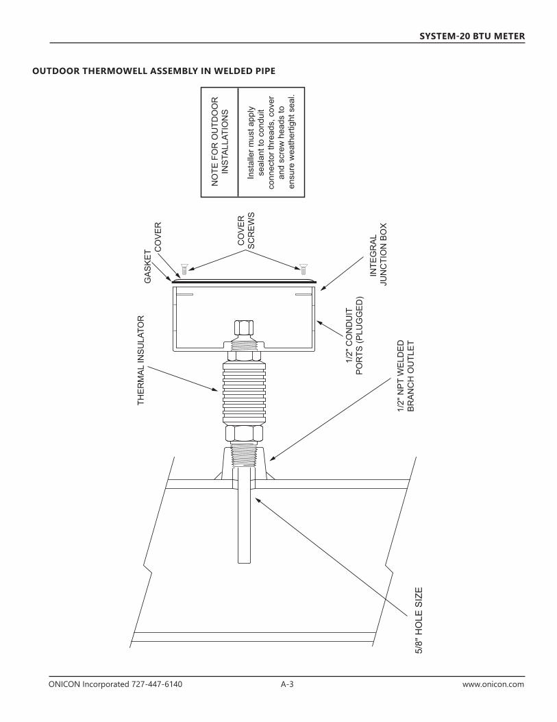
ONICON Incorporated 727-447-6140 A-3 www.onicon.com
SYSTEM-20 BTU METER
NO
TE F
OR
OU
TDO
OR
INS
TALL
ATIO
NS
Inst
alle
r mus
t app
ly
seal
ant t
o co
ndui
t co
nnec
tor t
hrea
ds, c
over
an
d sc
rew
hea
ds to
en
sure
wea
ther
tight
sea
l.
Th
erm
owel
l In
stal
lati
onIn
Wel
ded
Pip
e
04-1
401
95-1
1145
1 So
uth
Bel
cher
Roa
d, L
argo
, FL
3377
3 • U
SA •
Tel +
1 (7
27) 4
47-6
140
Fax
(727
) 442
-569
9w
ww
.oni
con.
com
E-m
ail:
sale
s@on
icon
.com
INTE
GR
AL
JUN
CTI
ON
BO
X
THE
RM
AL
INS
ULA
TOR
1/2"
NP
T W
ELD
ED
BR
AN
CH
OU
TLE
T5/
8" H
OLE
SIZ
E
GA
SK
ET C
OV
ER
CO
VE
RS
CR
EW
S
1/2"
CO
ND
UIT
PO
RTS
(PLU
GG
ED
)
OUTDOOR THERMOWELL ASSEMBLY IN WELDED PIPE

ONICON Incorporated 727-447-6140 A-4 www.onicon.com
SYSTEM-20 BTU METER
AVERTISSEMENTLes messages identifiés comme étant des « Avertissements » comportent de l'information concernant la sécurité personnelle des personnes impliquées dans l'installation, le fonctionnement et l'entretien de ce produit.
MISE EN GARDELes messages identifiés comme étant des « Mises en garde » comportent de l'information concernant les dommages potentiels qui pourraient affecter le produit ou tout autre produit connexe.
REMARQUE IMPORTANTELes messages identifiés comme étant des « Remarques importantes » comportent de l'information essentielle au bon fonctionnement du produit.
AVERTISSEMENTSeul un technicien qualifié devrait tenter d'installer ou d'effectuer l'entretien de ce produit. Des blessures graves peuvent découler de la mauvaise installation ou utilisation de ce produit.
1
4
3
2
ATTENTIONLa batterie du System-20 ne peut pas être ajoutée ou remplacée. Risque d'explosion d'incendie et de brûlures. NE PAS recharger, désassembler, écraser, chauffer à une température supérieure à 212 ° F (100 ° C) ou incinérer. Veuillez vérifier vos ordonnances locales pour des informations concernant la mise au rebut de la batterie.
5
REMARQUE IMPORTANTELe System-20 peut être installé à l'extérieur dans des espaces protégés à l'abri de la lumière directe du soleil, de la pluie, du grésil ou de la neige.
6
REMARQUE IMPORTANTEUne sélection appropriée du site est essentielle pour garantir la performance de ce compteur BTU. Le capteur de débit et les capteurs de température doivent être bien placés dans le système de canalisation afin de garantir la précision de la mesure énergétique.
7
REMARQUE IMPORTANTELes composantes du Système de mesure en BTU du Système-20 ONICON doivent être configurées, programmées et installées ensemble pour créer un système. Mélanger des composantes provenant de systèmes différents peut conduire à d'importantes erreurs de mesure.
8
FRENCH TRANSLATION OF ALL WARNING, CAUTION AND IMPORTANT NOTES (Traductions en français de tous les AVERTISSEMENTS, MISES EN GARDE ET REMARQUES IMPORTANTES)

ONICON Incorporated 727-447-6140 A-5 www.onicon.com
SYSTEM-20 BTU METER
MISE EN GARDELa liaison des raccords de conduits n'est pas automatique et devrait être fournie dans le cadre de l'installation.
9
MISE EN GARDENE PAS percer de trous dans le boîtier. N'utilisez que les orifices fournis.
10
MISE EN GARDENE PAS UTILISER LE BOÎTIER À TITRE DE MODÈLE POUR PERCER DES TROUS. Ne pas percer de trous dans le boîtier. N'utilisez que les orifices fournis.
11
REMARQUE IMPORTANTEIl est important de veiller à ce qu'aucune saleté ni autre corps étranger ne pénètre les puits thermométriques car ceci pourrait avoir un impact sur la réponse thermique du système.
12
MISE EN GARDELE SYSTÈME PEUT ÊTRE SOUS HAUTE PRESSION. Assurez-vous de maintenir fermement à la main la boîte de jonction avant de desserrer lentement l'écrou de serrage de la position lors de l'installation, du réglage ou du retrait du puits thermométrique. Le non respect de cette instruction laissera la pression expulser soudainement et rapidement le puits thermométrique du tuyau, ce qui pourrait entraîner des blessures graves. Le puits thermométrique pourrait également être endommagé ou brisé, provoquant ainsi une rupture dans le joint hydraulique et par conséquent la perte de grandes quantités d'eau.
13
MISE EN GARDEDes vibrations excessives risquent d'endommager le puits thermométrique. Insérez le puits thermométrique à la profondeur adéquate en utilisant la jauge fournie tel qu'indiqué. Diminuez la profondeur d'insertion au besoin si des fortes vibrations sont ressenties lors de l'insertion, en vous assurant que l'extrémité du puits thermométrique reste entièrement dans le flux.
14
MISE EN GARDENE PAS TROP SERRER L'ÉCROU DE SERRAGE DE LA POSITION. En cas de fuites de liquide, ne pas tenter d'y remédier en serrant encore plus l'écrou. Un joint torique d'étanchéité interne retient le liquide. Veuillez communiquer avec ONICON pour obtenir de l'aide en cas de fuite.
15
AVERTISSEMENTMaintenez un contrôle ferme sur le boîtier de câblage jusqu'à ce que le puits thermométrique soit complètement retiré et la vanne complètement fermée.
16
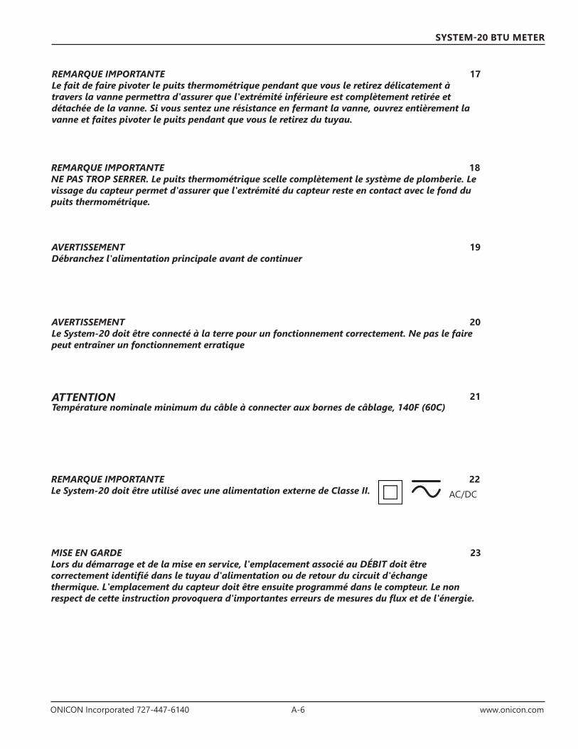
ONICON Incorporated 727-447-6140 A-6 www.onicon.com
SYSTEM-20 BTU METER
REMARQUE IMPORTANTELe fait de faire pivoter le puits thermométrique pendant que vous le retirez délicatement à travers la vanne permettra d'assurer que l'extrémité inférieure est complètement retirée et détachée de la vanne. Si vous sentez une résistance en fermant la vanne, ouvrez entièrement la vanne et faites pivoter le puits pendant que vous le retirez du tuyau.
17
REMARQUE IMPORTANTENE PAS TROP SERRER. Le puits thermométrique scelle complètement le système de plomberie. Le vissage du capteur permet d'assurer que l'extrémité du capteur reste en contact avec le fond du puits thermométrique.
18
MISE EN GARDELors du démarrage et de la mise en service, l'emplacement associé au DÉBIT doit être correctement identifié dans le tuyau d'alimentation ou de retour du circuit d'échange thermique. L'emplacement du capteur doit être ensuite programmé dans le compteur. Le non respect de cette instruction provoquera d'importantes erreurs de mesures du flux et de l'énergie.
23
AVERTISSEMENTDébranchez l'alimentation principale avant de continuer
AVERTISSEMENTLe System-20 doit être connecté à la terre pour un fonctionnement correctement. Ne pas le faire peut entraîner un fonctionnement erratique
19
20
ATTENTIONTempérature nominale minimum du câble à connecter aux bornes de câblage, 140F (60C)
21
REMARQUE IMPORTANTELe System-20 doit être utilisé avec une alimentation externe de Classe II.
22AC/DC

11451 Belcher Road South, Largo, FL 33773 • USA • Tel +1 (727) 447-6140 • Fax +1 (727) 442-5699www.onicon.com • [email protected]
SYSTEM-20 BTU METER
ONICONFlow and Energy Measurement