system 55 autopilot · cirrus airplane maintenance manual model sr22 22-11 page 1 all effectivity:...
TRANSCRIPT
C I R R U S A I R P L A N E M A I N T E N A N C E M A N U A L M O D E L S R 2 2
EFFECTIVITY:
SYSTEM 55 AUTOPILOT
1. DESCRIPTION
The S-TEC System 55 is a dual axis autopilot system that provides roll stability, heading hold, NAV/GPS tracking, altitude hold, vertical speed selection, automatic glideslope capture, and automatic 45° intercept to desired flight path capabilities controlled via the roll-trim cartridge and pitch trim servo. (See Figure 22-111)
The system components consist of a Flight Guidance Programmer/Computer, Altitude Selector/Alerter, Altitude Transducer, Turn Coordinator, and HSI. The operating controls for the autopilot are located on the Flight Guidance Programmer/Computer.
Through panel mounted switches and the vertical speed knob, the Flight Guidance Programmer/Computer serves the function of converting operator commands to logic signals for the roll and pitch computer func-tions. The roll computer receives signal inputs from the Turn Coordinator and HSI to compute roll com-mands for stabilization, turns, radio intercepts, heading and tracking. The pitch computer receives signal inputs from the Altitude Transducer, accelerometer, glideslope deviations, and Altitude Selector/Alerter.
Serials 0435 thru 1306 after SB 2X-22-03 and Serials 1307 & subs with optional installation: The Avidyne Flight Director is a visual reference displayed on the Primary Flight Display (PFD) to simplify flight by instrument navigation with or without the autopilot coupled. This feature requires System 55X Autopilot and PFD. The Flight Director display consists of a wedged Reference Symbol, indicating airplane attitude, and inverted-wedge Command Bars, indicating the recommended course attitude. To maintain selected course while in manual flight mode, the pilot maneuvers the airplane so the top of the Reference Symbol fits into the notch of the Command Bars.
The autopilot generates Flight Director Command Bars from modes selected on the Autopilot Computer, including HDG (Heading), NAV (VOR, LOC, or GPS), GPSS (GPS Steering), ALT (Altitude Hold), GS (Glideslope), and VS (Vertical Speed). The system consists of two lighted push buttons mounted on the upper LH instrument panel for uncoupling and recoupling the autopilot, and wiring harnesses for System 55X Autopilot and PFD communication. The Flight Director system is powered by 28 VDC through the 5-amp Autopilot circuit breaker on the Essential Avionics Bus. Refer to the manufacturer’s approved Instruc-tions For Continued Airworthiness and/or other service instructions.
22-11All
Page 115 Apr 2007
22-11 All
C I R R U S A I R P L A N E M A I N T E N A N C E M A N U A L M O D E L S R 2 2
Page 215 Apr 2007
EFFECTIVITY:
2. TROUBLESHOOTING
Trouble Probable Cause Remedy
Unexpected flight characteristics with autopilot engaged.
Moisture in static traps and/or sump.
Check traps and sump for mois-ture. Blow out lines.
Moisture in static line. Check lines for moisture. Perform System Test - Static Plumbing System (Refer to 34-10).

C I R R U S A I R P L A N E M A I N T E N A N C E M A N U A L M O D E L S R 2 2
EFFECTIVITY:
3. MAINTENANCE PRACTICES
A. Flight Guidance Programmer/Computer (See Figure 22-112)
(1) Removal - Flight Guidance Programmer/Computer(a) Set BAT 1, BAT 2, and AVIONICS master switches to OFF positions.(b) Pull AUTOPILOT circuit breaker.(c) Insert hex wrench into front panel bolt hole and engage locking screw.(d) Turn locking screw counter-clockwise to loosen locking cam. Cam will move the trans-
ceiver unit out 1/4” and disengage from the electrical connectors.(e) Pull Flight Guidance Programmer/Computer from mounting tray
(2) Installation - Flight Guidance Programmer/Computer(a) With light to medium pressure, push Guidance Programmer/Computer into mounting tray
to engage electrical connectors.(b) Insert hex wrench into front panel bolt hole and engage locking screw.(c) Turn locking screw clockwise to tighten locking cam.(d) Reset AUTOPILOT circuit breaker.(e) Perform the following Adjustment/Test whenever the original Flight Guidance Programmer/
Computer is replaced with a different Flight Guidance Programmer/Computer:1 Perform Functional Test - Flight Guidance Programmer/Computer. (Refer to 22-11)
(3) Functional Test - Flight Guidance Programmer/Computer(a) Serials equipped with HSI only; Ensure Flight Guidance Programmer/Computer is config-
ured as a NSD-360 compatible unit.(b) Serials equipped with PFD only; Ensure Flight Guidance Programmer/Computer is config-
ured as a KCS-55 compatible unit.
Note: The following steps are to be performed in-flight in VFR smooth air.
(c) Serials equipped with PFD and Serials equipped with HSI: While NAV (without GPSS) mode is engaged on the System 55x, using a GNS-430 GPS source, insert an appropri-ately sized screwdriver into the slotted hole to perform alignment procedures in accor-dance with the STEC installation instructions.
Note: The following steps are required for airplanes equipped with PFD only.
(d) Engage the 55x in HDG mode and allow aircraft to “settle on heading bug”. If heading bug agrees with aircraft heading, the system is calibrated. Otherwise, complete the remaining calibration steps.
(e) Turn both GNS-430 units off.(f) Enter the setup mode on the PFD by simultaneously pressing and holding L1 and L3 line
select keys until the count down timer in the lower left corner of the display indicates zero seconds.
(g) Turn both GNS-430's units back on.(h) Press R3 line select key “Perform A/P Cal”.(i) Press L1 line select key "Sync HDG”. Autopilot should immediately command aircraft to
turn toward heading bug.(j) Press L4 line select key “Back to PFD”.(k) Verify HDG mode accurately tracks heading bug. If autopilot does not track heading bug
correctly, repeat previous calibration steps.(l) Engage NAV (without GPSS) mode on autopilot.(m) Enter flight plan or waypoint and verify NAV mode accurately tracks flight plan. If autopilot
does not track NAV mode correctly, repeat previous calibration steps.
22-11All
Page 315 Apr 2007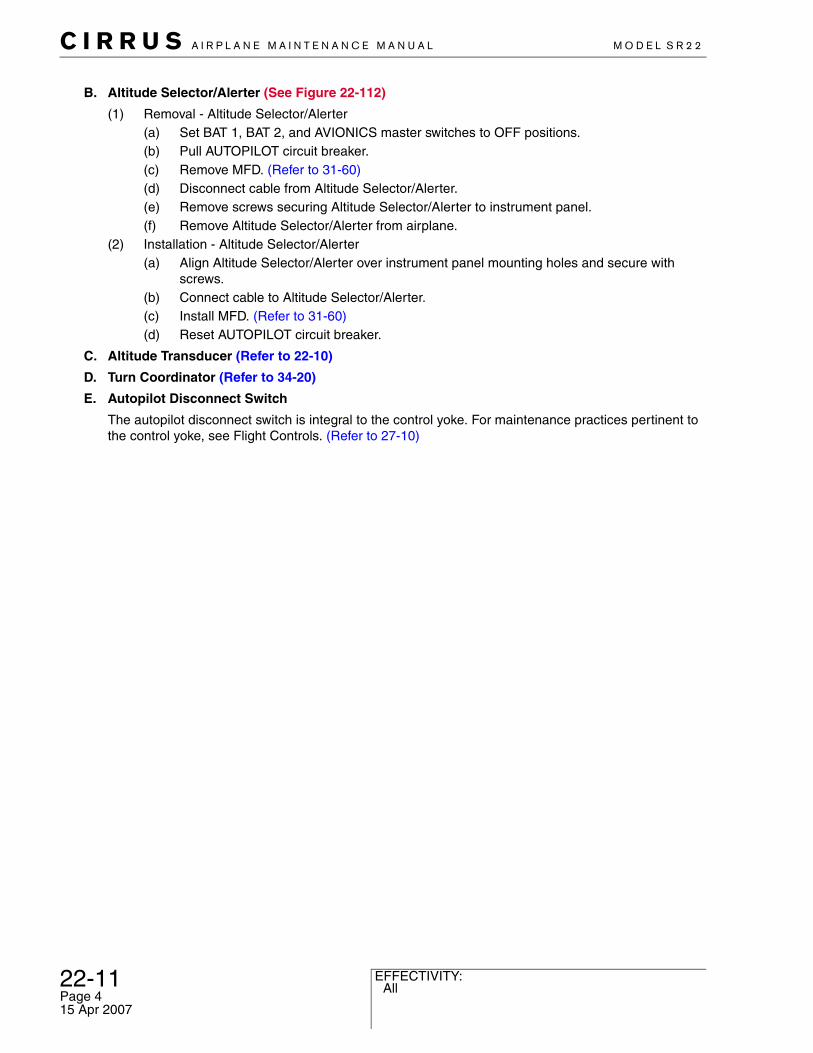
22-11 All
C I R R U S A I R P L A N E M A I N T E N A N C E M A N U A L M O D E L S R 2 2
Page 415 Apr 2007
EFFECTIVITY:
B. Altitude Selector/Alerter (See Figure 22-112)
(1) Removal - Altitude Selector/Alerter(a) Set BAT 1, BAT 2, and AVIONICS master switches to OFF positions.(b) Pull AUTOPILOT circuit breaker.(c) Remove MFD. (Refer to 31-60)(d) Disconnect cable from Altitude Selector/Alerter.(e) Remove screws securing Altitude Selector/Alerter to instrument panel.(f) Remove Altitude Selector/Alerter from airplane.
(2) Installation - Altitude Selector/Alerter (a) Align Altitude Selector/Alerter over instrument panel mounting holes and secure with
screws.(b) Connect cable to Altitude Selector/Alerter.(c) Install MFD. (Refer to 31-60)(d) Reset AUTOPILOT circuit breaker.
C. Altitude Transducer (Refer to 22-10)
D. Turn Coordinator (Refer to 34-20)
E. Autopilot Disconnect Switch
The autopilot disconnect switch is integral to the control yoke. For maintenance practices pertinent to the control yoke, see Flight Controls. (Refer to 27-10)

C I R R U S A I R P L A N E M A I N T E N A N C E M A N U A L M O D E L S R 2 2
EFFECTIVITY:
Figure 22-111System 55X Schematic - Serials w/o PFD (Sheet 1 of 2)
E
W
E
N
3
6
1215
21
24
30 33
157KTMAP OFF
311°
GPS1
302°284°
NAV
ILS1
314°
57.9 nm A 311°
360
SN3308SANDEL
VUE
BRG
MAP
NAV
A-BSHFT
ALTITUDE/VERTICALSPEED SELECTOR
TURN COORDINATOR HSI
VSDHALT
ENT
INC
TENTHS
PULL
VSDH
DTA
BAR
ALT ALR MAN
GNS 430 TRANSCEIVER
ROLL TRIM CARTRIDGE
RC
ED
RC
NI
VS x 100
SP
S
G
IA
L
F
SW
C
YD
R+VSGSALTREV TRIMAPRNAVHDG
FIFTY FIVE XS-TEC
VSALTAPR REVHDG NAV
SYNC
SR22_MM22_1339A
PITCH TRIM CARTRIDGE
ALTITUDE TRANSDUCER
RL2 MIN
TURN COORDINATOR
PITCH TRIM SERVO
22-11Serials w/o PFD
Page 515 Apr 2007
22-11 Serials w/ PFD
C I R R U S A I R P L A N E M A I N T E N A N C E M A N U A L M O D E L S R 2 2
Page 615 Apr 2007
EFFECTIVITY:
Figure 22-111System 55X Schematic - Serials w/ PFD (Sheet 2 of 2)
TURN COORDINATOR
2 MIN
L
R
TURN COORDINATOR
SYSTEM 55X AUTOPILOT
ROLL TRIM CARTRIDGE
SR22_MM22_2145
PITCH TRIM CARTRIDGE
FLIGHT DIRECTORSWITCHES
PITCH TRIM SERVO
GNS 430 TRANSCEIVER #2
GNS 430 TRANSCEIVER #1
PFD FAILRELAY
ALTITUDE TRANSDUCER
PFD

C I R R U S A I R P L A N E M A I N T E N A N C E M A N U A L M O D E L S R 2 2
EFFECTIVITY:
Figure 22-112System 55X Installation
ALTITUDETRANSDUCER
(REF)
Serials 1005 thru 1336and 1337 and subs
w/o PFD.
1
2
4
LEGEND 1. Screw 2. Cable Connector 3. Altitude/Vertical Speed Selector 4. Flight Guidance Program/Computer
3
SR22_MM22_1340B
22-11All
Page 715 Apr 2007
22-11 All
C I R R U S A I R P L A N E M A I N T E N A N C E M A N U A L M O D E L S R 2 2
Page 815 Apr 2007
EFFECTIVITY:
F. Pitch Trim Servo (See Figure 22-113)
(1) Removal - Pitch Trim Servo(a) Set BAT 1, BAT 2, and AVIONICS switches to OFF positions.(b) Pull AUTOPILOT circuit breaker.(c) Remove access panel CF5. (Refer to 06-00)(d) Serials 1602, 1840, 1863 & subs w/ Air Conditioning: Remove condenser. (Refer to 21-50)(e) Disconnect pitch trim servo plug from socket.
Note: Note location of bridle cable clamps on elevator cable to facilitate reinstalla-tion.
(f) Remove bolts, nuts, and clamps securing bridle cable to elevator cable.(g) Serials 1602, 1840, 1863 & subs w/ Air Conditioning: Remove screws, washers, and nuts
securing fairleads, bridle cable, and elevator cable to fairlead bracket.(h) Remove bolts and washers securing pitch trim servo to mounting bracket and remove
pitch trim servo from airplane.(2) Disassembly - Pitch Trim Servo
(a) Remove screws and washers securing capstan cover to capstan.(b) Remove cable guards.(c) Serials 1602, 1840, 1863 & subs w/ Air Conditioning: Remove cotter pin, nut, washers,
spacer, and bolt securing pulley and cable keeper to mounting bracket.(d) Remove cotter pin, nut, and washer securing tension washers to capstan.(e) Loosen set screw securing bridle cable stop-ball to capstan recess.(f) Remove stop-ball from capstan recess and unwrap bridle cable from capstan.(g) Remove screw and washer securing cover to servo motor.
(3) Reassembly - Pitch Trim Servo(a) Place tension washers on capstan and secure with washer and nut.(b) Perform Adjustment/Test - Pitch Trim Servo Torque. (Refer to 22-11)(c) Insert and depress bridle cable stop-ball into capstan recess and tighten set screw.(d) Serials 0002 thru 1367: Wrap bridle cable around servo capstan.
1 On servo capstan, position bridle cable stop-ball between 11 o’clock and 1 o’clock positions (stop-ball at top of capstan), and wrap aft bridle cable 540° counter-clock-wise.
2 On servo capstan, position bridle cable stop-ball between 11 o’clock and 1 o’clock positions (stop-ball at top of capstan), and wrap forward bridle cable 180° clockwise.
(e) Serials 1368 & subs: Wrap bridle cable around servo capstan.1 On servo capstan, position bridle cable stop-ball at 3 o’clock position (stop-ball at
back of capstan), and wrap long end of bridle cable 660° clockwise.2 On servo capstan, position bridle cable stop-ball at 3 o’clock position (stop-ball at
back of capstan), and wrap short end of bridle cable 660° counter-clockwise.
Note: Align cable keeper so arm extends through mounting bracket hole but does not contact pulley or mounting bracket.
(f) Serials 1602, 1840, 1863 & subs w/ Air Conditioning: Position pulley and cable keeper to mounting bracket and secure with bolt, washers, spacer, nut, and cotter pin.
(g) Install cable guards.(h) Position capstan cover to capstan and secure with screws and washers.(i) Position cover to servo motor and secure with screw and washer.
(4) Installation - Pitch Trim Servo

C I R R U S A I R P L A N E M A I N T E N A N C E M A N U A L M O D E L S R 2 2
EFFECTIVITY:
(a) Position pitch trim servo to mounting bracket and secure with bolts and washers.(b) Perform Adjustment/Test - Bridle Cable Tension. (Refer to 22-11)(c) Connect pitch trim servo plug to socket.(d) Serials 1602, 1840, 1863 & subs w/ Air Conditioning: Install condenser. (Refer to 21-50)(e) Install access panel CF5. (Refer to 06-00)(f) Reset AUTOPILOT circuit breaker.
(5) Adjustment/Test - Pitch Trim Servo Torque
(a) Acquire necessary tools, equipment, and supplies.
(b) Insert pins of spanner adapter into capstan tooling holes.(c) Position dial torque wrench to spanner adapter.(d) Push servo flapper down and adjust clutch torque to 35.0 ± 3.0 in-lb (3.9 ± 0.3 Nm).
Note: If it is necessary to rotate nut for cotter pin installation, it is allowable to remove thinnest (0.032”) tension washer from stackup to maintain specified torque.
(e) Install new cotter pin. If capstan nut must be rotated to install cotter pin, verify clutch torque is within recommended torque settings.
(6) Adjustment/Test - Bridle Cable Tension - Serials 0002 thru 1367
(a) Acquire necessary tools, equipment, and supplies.
(b) Remove access panel RE1. (Refer to 06-00)(c) Serials 0002 thru 0497: Insert lock-out pin at elevator empennage actuation pulley.(d) Serials 0498 thru 1367: Using rigging lock-out tool and pin, lock-out elevator empennage
bellcrank.(e) Using tensiometer, ensure elevator control cable tension is set to 30.0 - 40.0 lb (13.6 - 18.1
kg). If elevator control cable tension falls outside specified torque, perform Adjustment/Test - Elevator System Rigging. (Refer to 27-30) (Refer to 27-30)
(f) On servo capstan, position bridle cable stop-ball between 11 o’clock and 1 o’clock posi-tions (stop-ball at top of capstan).
Description P/N or Spec. Supplier Purpose
Spanner Adapter(1 of 2)
6622-1 S-TEC CorporationMineral Wells, TX 76067
Torque adjustment.
Spanner Adapter(2 of 2)
6624-1 S-TEC CorporationMineral Wells, TX 76067
Torque adjustment.
Description P/N or Spec. Supplier Purpose
Tensiometer BT-33-75D Kent-MooreWarren, MI 48092800-328-6657
Cable tension determination.
Rigging Lockout Tool 14905-001 Cirrus DesignDuluth, MN 55811218-727-2737
Lockout elevator bellcrank.
3/16” Lockout Pin - Any Source Lockout elevator bellcrank.
22-11All
Page 915 Apr 2007
22-11 All
C I R R U S A I R P L A N E M A I N T E N A N C E M A N U A L M O D E L S R 2 2
Page 1015 Apr 2007
EFFECTIVITY:
(g) Position aft bridle cable and clamp assembly to outboard elevator cable and loosely secure with bolts and nuts.
(h) Position forward bridle cable and clamp assembly to outboard elevator cable and loosely secure with bolts and nuts.
Note: Use a ratcheting open-end wrench and socket for tightening bridle cable clamp assembly to elevator cable.
(i) At forward bridle cable clamp assembly, push clamp assembly forward, tighten clamp to elevator cable.
Note: While tightening bridle cable clamp to elevator cable, capstan will rotate. Offset this rotation while adjusting opposite bridle cable tension so that when specified tension is reached, the bridle cable stop-ball is between 11 o’clock and 1 o’clock positions (stop-ball at top of capstan).
(j) At aft bridle cable clamp assembly, push clamp assembly aft while tightening clamp to ele-vator cable.
(k) Using the techniques described above, adjust bridle cable tension to 17.0 ± 4.0 lb (7.7 ± 1.8 kg).
(l) Serials 0002 thru 0497: Remove lock-out pin from elevator actuation pulley.(m) Serials 0498 thru 1367: Remove rigging lock-out pin and tool from elevator empennage
bellcrank.(n) Install access panel RE1. (Refer to 06-00)
(7) Adjustment/Test - Bridle Cable Tension - Serials 1368 & subs
(a) Acquire necessary tools, equipment, and supplies.
(b) Remove access panel RE1. (Refer to 06-00)(c) Using rigging lock-out tool and pin, lock-out elevator empennage bellcrank.(d) Using tensiometer, verify elevator control cable tension is set to 30.0 - 40.0 lb (13.6 - 18.1
kg). If elevator control cable tension falls outside specified tolerance, perform Adjustment/Test - Elevator System Rigging. (Refer to 27-30) (Refer to 27-30)
(e) On servo capstan, position bridle cable stop-ball at 3 o’clock position (stop-ball at back of capstan).
Note: Use a ratcheting open-end wrench and socket for tightening bridle cable clamp assembly to elevator cable.
Description P/N or Spec. Supplier Purpose
Tensiometer BT-33-75D Kent MooreWarren, MI 48092
Cable tension determination.
Rigging Lockout Tool 14905-001 Cirrus DesignDuluth, MN 55811218-727-2737
Lockout elevator bellcrank.
3/16” Lockout Pin - Any Source Lockout elevator bellcrank.

C I R R U S A I R P L A N E M A I N T E N A N C E M A N U A L M O D E L S R 2 2
EFFECTIVITY:
Install outboard clamp assembly with bolt heads facing inboard and inboard clamp assembly with bolt heads facing outboard. Align bolt shafts approxi-mately perpendicular to 0.0 buttock line. Ensure maximum gap of 0.01 inch (0.25 mm) between aft end of clamp and bridle cable end fitting.
(f) Position short end of bridle cable and clamp assembly to outboard elevator cable and secure with bolts and nuts. Torque nuts to 55 ± 5 in-lb (6.2 ± 0.6 Nm). With elevator at 0° deflection, ensure forward end of clamp is a minimum of 5.5 in (14.0 cm) from aft edge of servo.
(g) Serials 1368 thru 1601, 1603 thru 1839, 1841 thru 1862, 1863 & subs w/o Air Condition-ing: Position long end of bridle cable and clamp assembly to inboard elevator cable and loosely secure with bolts and nuts. With elevator at 0° deflection, ensure forward end of clamp assembly is a minimum of 19.0 in (48.2 cm) from aft edge of servo.
(h) Serials 1602, 1840, 1863 & subs w/ Air Conditioning: Route long end of bridle cable through mounting bracket hole and between pulley and cable keeper.
(i) Serials 1602, 1840, 1863 & subs w/ Air Conditioning: Position long end of bridle cable and clamp assembly to inboard elevator cable and loosely secure with bolts and nuts. With ele-vator at 0° deflection, ensure forward end of clamp assembly is a minimum of 18.4 in (46.7 cm) from aft edge of servo.
(j) While pushing long end of bridle cable and clamp assembly aft, tighten clamp to elevator cable. Torque nuts to 55 ± 5 in-lb (6.2 ± 0.6 Nm).
(k) Using tensiometer, verify bridle cable tension forward of bridle cable clamps is set to 25.0 ± 5.0 lb (11.3 ± 2.3 kg). If bridle cable tension falls outside specified tolerance, loosen aft clamp assembly and adjust bridle cable as required to obtain 25.0 ± 5.0 lb (11.3 ± 2.3 kg).
(l) Using tensiometer, verify elevator control cable tension forward of the bridle cable clamp assemblies is set to 30.0 - 40.0 lb (13.6 - 18.1 kg).
(m) Serials 1602, 1840, 1863 & subs w/ Air Conditioning: Position fairleads and cables to fair-lead bracket and secure with screws, washers, and nuts.
(n) Remove rigging lock-out pin and tool from elevator empennage bellcrank.(o) Ensure flight control systems operate through full range of travel without binding, obstruc-
tion, or excessive friction.(p) Ensure bridle cable remains in capstan grooves during full elevator and pitch trim servo
travel and bridle cable moves freely through cable guards without chafing.(q) Serials 1602, 1840, 1863 & subs w/ Air Conditioning: Ensure bridle cable moves freely
through mounting bracket without chafing.(r) Install access panel RE1. (Refer to 06-00)
22-11All
Page 1115 Apr 2007
22-11 Serials 0002 thru 1367
C I R R U S A I R P L A N E M A I N T E N A N C E M A N U A L M O D E L S R 2 2
Page 1215 Apr 2007
EFFECTIVITY:
Figure 22-113Pitch Trim Servo Installation - Serials 0002 thru 1367 (Sheet 1 of 3)
SR22_MM22_1509B
LEGEND 1. Flapper 2. Plug 3. Screw 4. Washer 5. Capstan 6. Nut 7. Clamp 8. Bridle Cable 9. Bolt10. Star Washer11. Capstan Cover12. Castellated Nut13. Cotter Pin14. Cable Guard15. Tension Washer16. Servo Motor Cover17. Bridle Cable Stop Ball
Ensure bridle cable does not rub on cable guards.
NOTEBefore disassembly, mark location of bridle cable.
FUSELAGE BELLY(REF)
17
SPANNER ADAPTER
12
1
9
9
5
ELEVATORCABLE (REF)
2
13
15
4
14
11
310
4
87
7
6BRACKET
(REF)
43
Serials 0002 thru 1367.

C I R R U S A I R P L A N E M A I N T E N A N C E M A N U A L M O D E L S R 2 2
EFFECTIVITY:
Figure 22-113Pitch Trim Servo Installation - Serials 1368 - 1601, 1603 - 1839, 1841 - 1862, 1863 & subs w/o A/C (Sheet 2 of 3)
Serials 1368 thru 1601, 1603 thru 1839, 1841 thru 1862,1863 & subs w/o Air Conditioning.
SR22_MM22_2137A
6
7
79
16
8
1
5
1514
12
13
94
2
43
3SPANNER ADAPTER
ELEVATORCABLE (REF)
BRACKET(REF)
BULKHEAD FS186(REF)
LEGEND 1. Flapper 2. Plug 3. Screw 4. Washer 5. Capstan 6. Nut 7. Clamp 8. Bridle Cable 9. Bolt10. Star Washer11. Capstan Cover12. Castellated Nut13. Cotter Pin14. Cable Guard15. Tension Washer16. Servo Motor Cover17. Bridle Cable Stop-Ball18. Bridle Cable End Fitting
Install outboard clamp assembly with bolt heads facing inboard and inboard clamp assembly with bolt heads facing outboard. Align bolt shafts approximately perpendicular to 0.0 buttock line.
NOTEBefore disassembly, mark location of bridle cable.
45.5 inches(14.0 cm)
19.0 inches(48.2 cm)
1011
Ensure bridle cable does not rub on cable guards.
0.0 BUTTOCK LINE (REF)
0.01 inches(0.25 mm)maximun
7
7
18
18
17
22-11Serials 1368 - 1601, 1603 - 1839, 1841 - 1862, 1863 & subs w/o A/C
Page 1315 Apr 2007

22-11 Serials 1602, 1840, 1863 & subs w/ A/C
C I R R U S A I R P L A N E M A I N T E N A N C E M A N U A L M O D E L S R 2 2
Page 1415 Apr 2007
EFFECTIVITY:
Figure 22-113Pitch Trim Servo Installation - Serials 1602, 1840, 1863 & subs w/ A/C (Sheet 3 of 3)
Serials 1602, 1840, 1863 & subs w/ Air Conditioning.
13
94
23
22
214
24
6
46
0.01 inches(0.25 mm)maximun
2
SR22_MM22_2338
7
16
8
1
5
15
1412
13
94
43
3
SPANNERADAPTER
ELEVATORCABLE (REF)
BRACKET(REF)
BULKHEAD FS186(REF)
LEGEND 1. Flapper 2. Plug 3. Screw 4. Washer 5. Capstan 6. Nut 7. Clamp 8. Bridle Cable 9. Bolt10. Star Washer11. Capstan Cover12. Castellated Nut13. Cotter Pin14. Cable Guard15. Tension Washer16. Servo Motor Cover17. Bridle Cable Stop-Ball18. Bridle Cable End Fitting19. Fairlead20. Bracket21. Pulley22. Cable Keeper23. Spacer24. Servo Bracket Plate
Install outboard clamp assembly with bolt heads facing inboard and inboard clamp assembly with bolt heads facing outboard. Align bolt shafts approximately perpendicular to 0.0 buttock line.
NOTEBefore disassembly, mark location of bridle cable.
4
10
11
Ensure bridle cable does not rub on cable guards.
0.0 BUTTOCK LINE (REF)
718
17
18.4 inches(46.7 cm)
5.5 inches(14.0 cm)
9
9
4
7
3
6
19
20
6
C I R R U S A I R P L A N E M A I N T E N A N C E M A N U A L M O D E L S R 2 2
EFFECTIVITY:
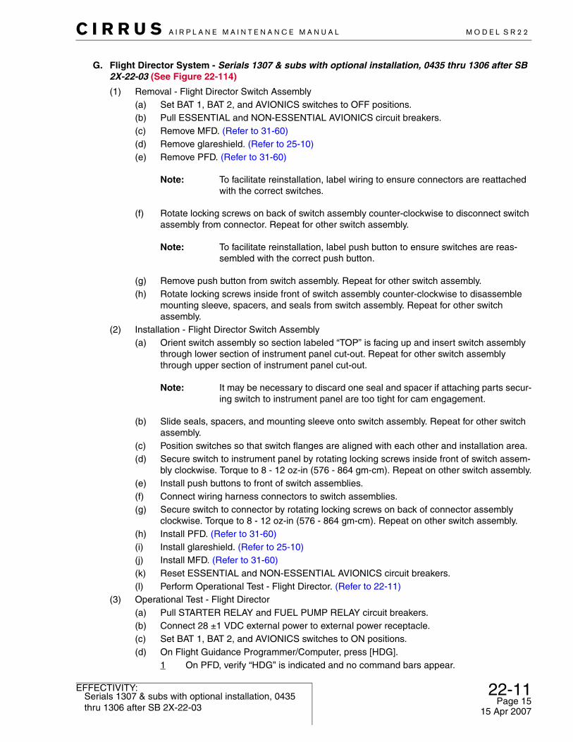
G. Flight Director System - Serials 1307 & subs with optional installation, 0435 thru 1306 after SB 2X-22-03 (See Figure 22-114)
(1) Removal - Flight Director Switch Assembly(a) Set BAT 1, BAT 2, and AVIONICS switches to OFF positions.(b) Pull ESSENTIAL and NON-ESSENTIAL AVIONICS circuit breakers.(c) Remove MFD. (Refer to 31-60)(d) Remove glareshield. (Refer to 25-10)(e) Remove PFD. (Refer to 31-60)
Note: To facilitate reinstallation, label wiring to ensure connectors are reattached with the correct switches.
(f) Rotate locking screws on back of switch assembly counter-clockwise to disconnect switch assembly from connector. Repeat for other switch assembly.
Note: To facilitate reinstallation, label push button to ensure switches are reas-sembled with the correct push button.
(g) Remove push button from switch assembly. Repeat for other switch assembly.(h) Rotate locking screws inside front of switch assembly counter-clockwise to disassemble
mounting sleeve, spacers, and seals from switch assembly. Repeat for other switch assembly.
(2) Installation - Flight Director Switch Assembly(a) Orient switch assembly so section labeled “TOP” is facing up and insert switch assembly
through lower section of instrument panel cut-out. Repeat for other switch assembly through upper section of instrument panel cut-out.
Note: It may be necessary to discard one seal and spacer if attaching parts secur-ing switch to instrument panel are too tight for cam engagement.
(b) Slide seals, spacers, and mounting sleeve onto switch assembly. Repeat for other switch assembly.
(c) Position switches so that switch flanges are aligned with each other and installation area.(d) Secure switch to instrument panel by rotating locking screws inside front of switch assem-
bly clockwise. Torque to 8 - 12 oz-in (576 - 864 gm-cm). Repeat on other switch assembly.(e) Install push buttons to front of switch assemblies.(f) Connect wiring harness connectors to switch assemblies. (g) Secure switch to connector by rotating locking screws on back of connector assembly
clockwise. Torque to 8 - 12 oz-in (576 - 864 gm-cm). Repeat on other switch assembly.(h) Install PFD. (Refer to 31-60)(i) Install glareshield. (Refer to 25-10)(j) Install MFD. (Refer to 31-60)(k) Reset ESSENTIAL and NON-ESSENTIAL AVIONICS circuit breakers.(l) Perform Operational Test - Flight Director. (Refer to 22-11)
(3) Operational Test - Flight Director(a) Pull STARTER RELAY and FUEL PUMP RELAY circuit breakers.(b) Connect 28 ±1 VDC external power to external power receptacle.(c) Set BAT 1, BAT 2, and AVIONICS switches to ON positions.(d) On Flight Guidance Programmer/Computer, press [HDG].
1 On PFD, verify “HDG” is indicated and no command bars appear.
22-11Serials 1307 & subs with optional installation, 0435 thru 1306 after SB 2X-22-03
Page 1515 Apr 2007

22-11 Serials 1307 & subs with optional installation, 0435 thru 1306 after SB 2X-22-03
C I R R U S A I R P L A N E M A I N T E N A N C E M A N U A L M O D E L S R 2 2
Page 1615 Apr 2007
EFFECTIVITY:
2 At lower Flight Director switch, verify [AP ON] push button is lit.(e) On Flight Guidance Programmer/Computer, press [ALT].
1 On PFD, verify “ALT” is indicated and solid magenta command bars (autopilot cou-pled) appear.
(f) Verify flight control functions.1 On PFD, press [HDG Bug].2 Rotate right knob counter-clockwise to position heading bug left.
Command bars should bank left, and yoke should rotate left.
3 Rotate right knob clockwise to position heading bug right. Command bars should bank right, and yoke should rotate right.
4 Adjust right knob to center heading bug.Command bars should return to center at wings level, and yoke should have little to no movement.
5 Press [VSI Bug].6 Adjust right knob to position VSI bug to "+1000".7 On Flight Guidance Programmer/Computer, press [VS].
On PFD, “VS” is indicated and command bars should climb. Yoke should move aft.
8 On PFD, adjust right knob to position VSI bug to “-1000”. Command bars should descend, and yoke should move forward.
(g) At upper Flight Director switch, press [AP OFF FD ON] push button.1 Verify autopilot disconnect tone (two beeps) is heard. 2 On PFD, verify command bars turn green (autopilot uncoupled).3 At upper Flight Director switch, verify [AP OFF FD ON] push button is lit.
(h) Repeat flight control functions verification.1 Verify command bars respond, but yoke does not move.
(i) On yoke, press autopilot disconnect switch to turn off autopilot.1 On PFD, verify command bars disappear.2 At upper Flight Director switch, verify [AP OFF FD ON] push button remains lit.
(j) At lower Flight Director switch, press [AP ON] push button.1 At upper Flight Director switch, verify [AP OFF FD ON] push button is not lit.2 At lower Flight Director switch, verify [AP ON] push button is not lit.
(k) Set BAT 1, BAT 2, and AVIONICS switches to OFF positions.(l) Disconnect 28 ±1 VDC external power from external power receptacle.(m) Reset STARTER RELAY and FUEL PUMP RELAY circuit breakers.

C I R R U S A I R P L A N E M A I N T E N A N C E M A N U A L M O D E L S R 2 2
EFFECTIVITY:
Figure 22-114Flight Director Installation - Serials 1307 & subs with optional installation, 0435 thru 1306 after SB 2X-22-03
SR22_MM22_2066
LEGEND 1. Pushbutton 2. Switch 3. Seal 4. Spacer 5. Mounting Sleeve 6. Connector 7. Screw 8. Relay 9. Washer10. Nut
NOTE
To release/engage cams, rotate lockingscrews clockwise/counter-clockwise.
25 7
41
8 10
6
3
1211
9
NC
NO
C
INSTRUMENT PANEL(REF)
7
6
54
43
3
2
1
8
910
TO RADIO MODULE(REF)
WIRING HARNESS(REF)
To facilitate switch installation, discard oneseal and spacer if required.
22-11Serials 1307 & subs with optional installation, 0435 thru 1306 after SB 2X-22-03
Page 1715 Apr 2007

22-11 All
C I R R U S A I R P L A N E M A I N T E N A N C E M A N U A L M O D E L S R 2 2
Page 1815 Apr 2007
EFFECTIVITY:
Intentionally Left Blank